

Page 1

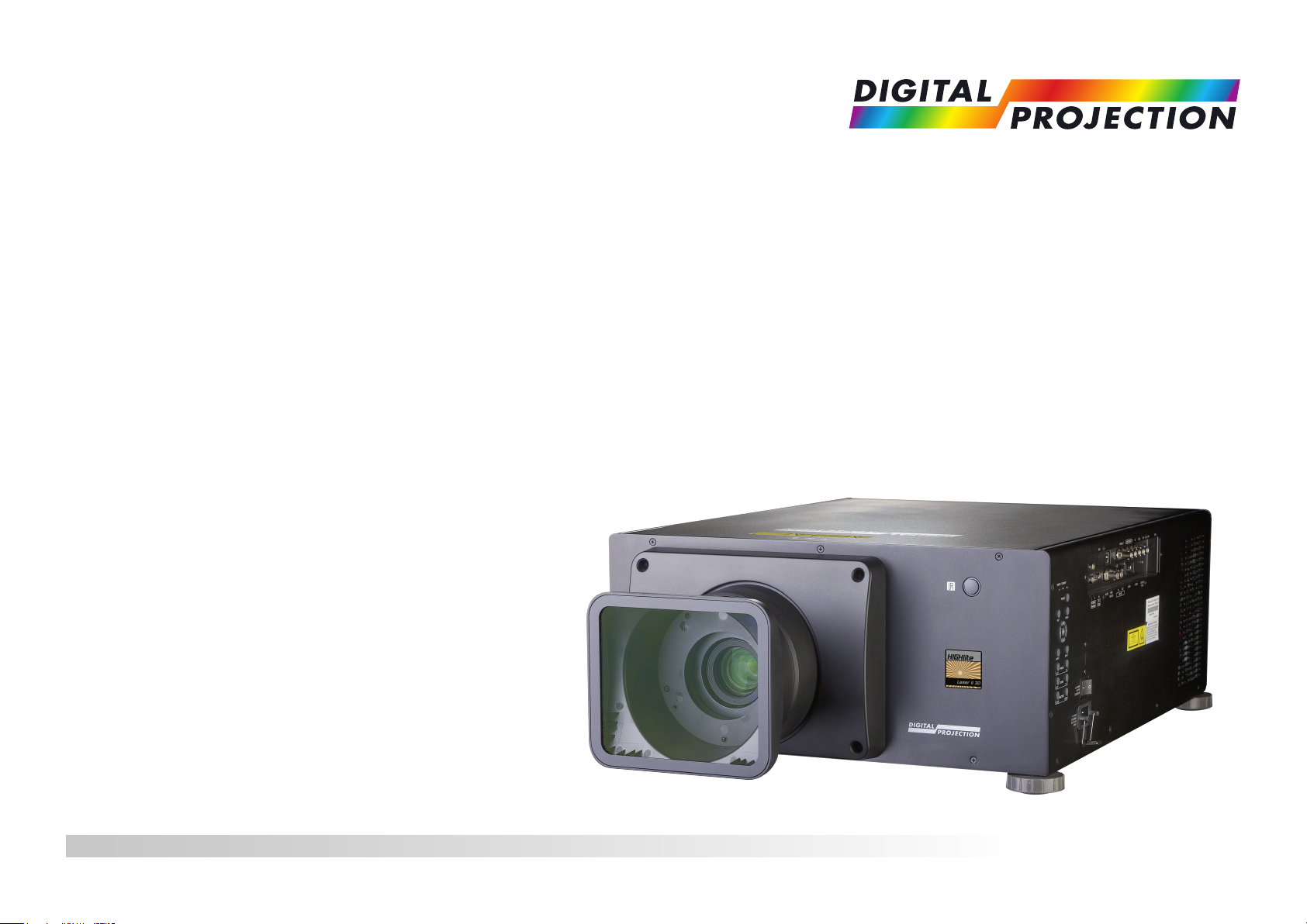
HIGHlite Laser II 3D Series
High Brightness Digital Video Projector
4INSTALLATION AND QUICK-START GUIDE
4CONNECTION GUIDE
4OPERATING GUIDE
4REFERENCE GUIDE
Rev B December 2016
118-089B
Page 2
Digital Projection HIGHlite Laser II 3D Series
About This Document
Follow the instructions in this manual carefully to ensure safe and long-lasting use of the projector.
Symbols used in this manual
Many pages in this document have a dedicated area for notes. The information in that area is accompanied by the following symbols:
WARNING: this symbol indicates that there is a danger of physical injury to yourself and/or damage to the equipment unless
the instructions are closely followed.
ELECTRICAL WARNING: this symbol indicates that there is a danger of electrical shock unless the instructions are closely
followed.
LASER WARNING: this symbol indicates that there is a potential hazard of eye exposure to laser radiation unless the
instructions are closely followed.
NOTE: this symbol indicates that there is some important information that you should read.
Product revision
Because we at Digital Projection continually strive to improve our products, we may change specications and designs, and add new features
without prior notice.
Notes
Legal notice
Trademarks and trade names mentioned in this document remain the property of their respective owners.
Digital Projection disclaims any proprietary interest in trademarks and trade names other than its own.
Copyright © 2016 Digital Projection Ltd. All rights reserved.
Rev B December 2016
page i
Page 3
Digital Projection HIGHlite Laser II 3D Series
상호명/제조자: 델타일렉트로닉스㈜
제조공장/제조국가: 델타 비디오 디스플레이
시스템 (우장) 리미티드
제조시기 : 년 월
116-330
S/N:
M/F Date:
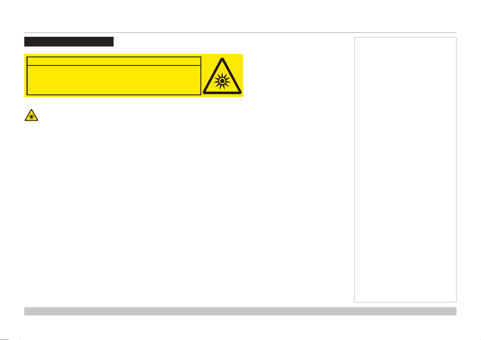
Laser Information
RISK GROUP 2
Possibly hazardous optical radiation emitted
Do not stare at operating lamp.
Caution-useofcontrolsoradjustmentsorperformanceofproceduresotherthanthosespeciedhereinmayresultin
hazardous radiation exposure.
CAUTION
Ce produit peut émettre des rayonnements
from this product.
Ne pas fixer la lampe en fonctionnement.
May be harmful to the eyes.
ATTENTION
optiques dangereux.
Peut être nocif pour les yeux.
Notes
Rev B December 2016
page ii
Page 4
Digital Projection HIGHlite Laser II 3D Series
Introduction
Congratulations on your purchase of this Digital Projection product.
Your projector has the following key features:
• Support for most 3D formats.
• HDBaseT
• 3G-SDI with loop-through.
• Edge Blend.
• Blanking control for custom input window sizing.
• Cornerstone, Vertical & Horizontal Keystone, Pincushion & Barrel, and Image Rotation.
• Control via LAN and RS232.
• Motorised lens mount.
A serial number is located on the side of the projector. Record it here:
®
for transmission of uncompressed High Denition Video up to 100 m from the source.
Notes
Rev B December 2016
page iii
Page 5

Digital Projection HIGHlite Laser II 3D Series
CONTENTS
INSTALLATION AND QUICK-START GUIDE ..............................1
WHAT’S IN THE BOX? ................................................................... 3
CONNECTING THE POWER SUPPLY ............................................. 4
Voltage selection ................................................................................... 4
PROJECTOR OVERVIEW ............................................................... 5
Front and rear views ............................................................................. 5
Control panel ......................................................................................... 6
REMOTE CONTROL ....................................................................... 7
Infrared reception ................................................................................ 10
POSITIONING THE SCREEN AND PROJECTOR ........................... 11
Roll and pitch ...................................................................................... 12
CHANGING THE LENS ................................................................. 13
The lens hood ..................................................................................... 13
Inserting a new lens ............................................................................ 14
Removing the lens .............................................................................. 15
CHANGING THE FILTERS ............................................................ 16
OPERATING THE PROJECTOR .................................................... 17
Switching the projector on ................................................................... 17
Switching the projector off ................................................................... 17
Selecting an input signal ..................................................................... 18
Selecting a test pattern ....................................................................... 18
Adjusting the lens ................................................................................ 19
Adjusting the image............................................................................. 19
CONNECTION GUIDE ............................................................................21
SIGNAL INPUTS .......................................................................... 23
Digital inputs and outputs .................................................................... 23
Analog inputs and outputs................................................................... 24
EDID on the HDMI, DisplayPort and VGA inputs ................................ 25
Using HDMI/DisplayPort switchers with the projector ......................... 25
3D connections ................................................................................... 26
3D sources up to 60Hz requiring frame doubling and left/right interleaving .......... 26
Frame sequential 3D sources up to 120Hz ................................................. 26
Dual Pipe 3D ...................................................................................... 26
3D Sync............................................................................................... 27
3D Sync in ......................................................................................... 27
3D Sync out ....................................................................................... 27
CONTROL CONNECTIONS ........................................................... 28
LAN connection examples .................................................................. 29
RS232 connection example ................................................................ 30
Rev B December 2016
page iv
Page 6

Digital Projection HIGHlite Laser II 3D Series
CONTENTS (continued)
OPERATING GUIDE ................................................................................31
USING THE MENUS ..................................................................... 33
Opening the OSD ................................................................................ 33
Opening a menu.................................................................................. 33
Exiting menus and closing the OSD.................................................... 33
Inside a menu...................................................................................... 34
Accessing sub-menus ........................................................................... 34
Executing commands............................................................................ 34
Editing projector settings ..................................................................... 35
Using a slider to set a value .................................................................... 35
Editing numeric values .......................................................................... 35
USING THE PROJECTOR ............................................................. 36
Main menu .......................................................................................... 36
Lens menu .......................................................................................... 37
Lens Control ....................................................................................... 37
Lens Memory ...................................................................................... 38
Image menu ........................................................................................ 39
Noise Reduction .................................................................................. 40
Position and Phase .............................................................................. 40
Color menu.......................................................................................... 41
Color Space ....................................................................................... 41
Color Mode ........................................................................................ 42
Geometry menu .................................................................................. 47
Aspect Ratio ....................................................................................... 47
Digital Zoom & Shift .............................................................................. 49
Overscan ........................................................................................... 50
Blanking ............................................................................................ 51
Keystone ........................................................................................... 52
4 Corners .......................................................................................... 54
Rotation ............................................................................................ 55
Pincushion / Barrel ............................................................................... 56
Edge Blend menu................................................................................ 57
Blend Width........................................................................................ 58
Black Level Uplift ................................................................................. 59
3D menu.............................................................................................. 60
3D types ............................................................................................ 61
Some 3D settings explained ................................................................... 62
Frame rate multiplication in 3D images ...................................................... 63
Laser menu ......................................................................................... 64
Setup menu ......................................................................................... 65
ColorMax Setting ................................................................................. 67
Power On/Off ...................................................................................... 68
Clock Adjust ....................................................................................... 69
OSD Settings ...................................................................................... 70
Memory ............................................................................................. 70
Network menu ..................................................................................... 71
PIP menu ............................................................................................ 72
Information menu ................................................................................ 73
Signal Format ..................................................................................... 73
System Status .................................................................................... 74
Thermal Status.................................................................................... 74
Factory Reset ..................................................................................... 75
POSSIBLE COMBINATIONS OF SETTINGS .................................. 76
Rev B December 2016
page v
Page 7

Digital Projection HIGHlite Laser II 3D Series
CONTENTS (continued)
REFERENCE GUIDE ................................................................................77
THE DMD™ .................................................................................. 80
CHOOSING A LENS ..................................................................... 82
Basic calculation ................................................................................. 83
Basic calculation example ................................................................... 84
Full lens calculation ............................................................................. 85
Introducing TRC .................................................................................. 85
Calculating TRC .................................................................................. 86
Calculating the throw ratio with TRC ......................................................... 87
Full lens calculation example .............................................................. 88
SCREEN REQUIREMENTS ........................................................... 89
Fitting the image to the DMD™ ........................................................... 89
WUXGA images displayed full width ......................................................... 89
WUXGA images displayed with a height of 1080 pixels .................................. 90
WUXGA images displayed full height ........................................................ 91
Diagonal screen sizes ......................................................................... 92
Fitting the image to the screen ............................................................ 93
Positioning the screen and projector ................................................... 94
POSITIONING THE IMAGE ........................................................... 95
Maximum offset range ......................................................................... 97
2:3:3:2 (advanced) pulldown ................................................................. 103
APPENDIX A: LENS PART NUMBERS ........................................ 104
APPENDIX B: LENS CHARTS .................................................... 105
How to use the lens charts ................................................................... 105
TRC values applied in the charts ........................................................... 106
Fixed lenses - full DMD™ width images ................................................... 107
Zoom lenses - full DMD™ width images .................................................. 108
Fixed lenses - 1.25:1 images ................................................................ 109
Zoom lenses - 1.25:1 images ................................................................ 110
Fixed lenses - 1.33:1 images .................................................................111
Zoom lenses - 1.33:1 images ................................................................ 112
APPENDIX C: SUPPORTED SIGNAL INPUT MODES ...................113
2D formats......................................................................................... 113
3D formats......................................................................................... 115
APPENDIX D: MENU MAP ...........................................................117
ASPECT RATIOS EXPLAINED ...................................................... 98
Aspect ratio examples ......................................................................... 99
FRAME RATES AND PULLDOWNS EXPLAINED ......................... 101
Interlaced and progressive scan ....................................................... 101
Frame rates of image sources .......................................................... 101
Pulldowns - conversion into destination formats ............................... 102
2:3 (normal) pulldown ......................................................................... 102
Rev B December 2016
page vi
Page 8

Digital Projection HIGHlite Laser II 3D Series
CONTENTS (continued)
APPENDIX E: WIRING DETAILS ................................................. 128
Signal inputs and outputs .................................................................. 128
VGA ............................................................................................... 128
HDMI 1 and 2 ................................................................................... 129
DisplayPort ...................................................................................... 130
3G-SDI In, 3G-SDI Out ........................................................................ 131
COMPONENT .................................................................................. 131
Control connections .......................................................................... 132
LAN ............................................................................................... 132
RS232 ............................................................................................ 132
Trigger 1 & Trigger 2 ........................................................................... 133
IR input ........................................................................................... 133
3D Sync IN and 3D Sync OUT .............................................................. 133
APPENDIX F: GLOSSARY OF TERMS ........................................ 134
TECHNICAL SPECIFICATIONS .................................................. 145
Models............................................................................................... 145
Inputs and outputs............................................................................. 146
Bandwidth ......................................................................................... 146
Remote control and keypad .............................................................. 146
Automation control ............................................................................ 146
Color temperature ............................................................................. 146
Lenses............................................................................................... 147
Lens mount ....................................................................................... 147
Mechanical mounting ........................................................................ 147
Orientation......................................................................................... 147
Electrical and physical specications ................................................ 148
Safety & EMC regulations ................................................................. 148
Rev B December 2016
page vii
Page 9

HIGHlite Laser II 3D Series
High Brightness Digital Video Projector
4
INSTALLATION AND QUICK-START GUIDE
Rev B December 2016
Page 10

Digital Projection HIGHlite Laser II 3D Series
IN THIS GUIDE
IN THIS GUIDE
What’s In The Box? ............................................................................................. 3
Connecting The Power Supply ........................................................................ 4
Voltage selection ......................................................................................................... 4
Projector Overview ............................................................................................. 5
Front and rear views ...................................................................................................5
Control Panel ........................................................................................................ 6
Remote Control .................................................................................................... 7
Infrared reception ......................................................................................................10
Positioning The Screen And Projector ....................................................... 11
Roll and pitch ............................................................................................................12
Changing The Lens ........................................................................................... 13
The lens hood ............................................................................................................13
Inserting a new lens ..................................................................................................14
Removing the lens ....................................................................................................15
Changing The Filters ........................................................................................ 16
Operating The Projector ................................................................................. 17
Switching the projector on .......................................................................................17
Switching the projector off .......................................................................................17
Selecting an input signal ..........................................................................................18
Selecting a test pattern .............................................................................................18
Adjusting the lens .....................................................................................................19
Adjusting the image ..................................................................................................19
Installation and Quick-Start Guide
Rev B December 2016
Page 11
Digital Projection HIGHlite Laser II 3D Series
PicMute
MENU
EXIT INFO
HDMI1
OK
OFF ON
ALT
LENS
FOCUS ZOOM
IN
OUT
IN
OUT
SHIFT
21 3
HDMI2 DVI
DISPLAYPORT
HD-T 3GSDI
VGA COMP1 COMP2
BRI
TEST
CON GAMMA
R G B ALL
3D EYE PIP SWAP
4 5 6
7 8 9 0
ALT
ADDR
OSD
OFF
ON
DEFAULT
FREEZE
RE-SYNC
A B C D
USERPRESET
OPEN CLOSE
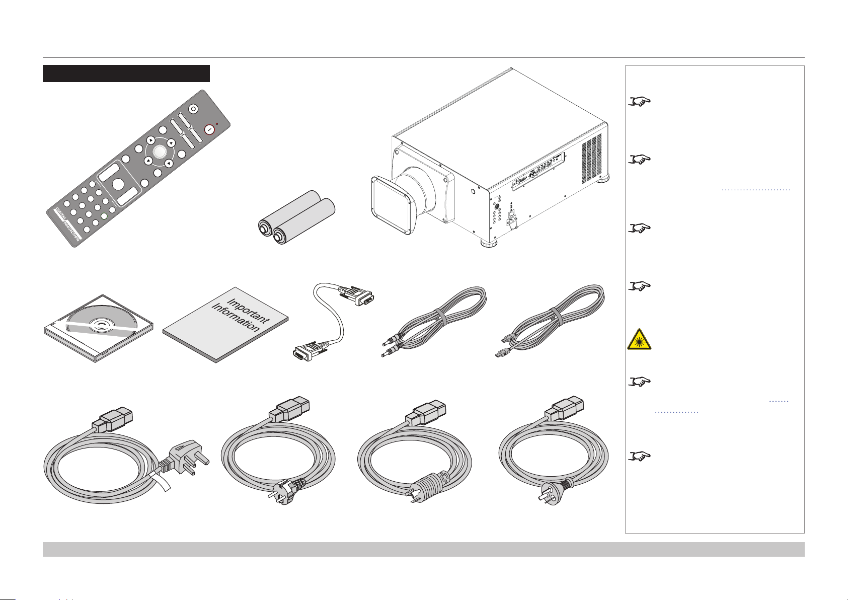
WHAT’S IN THE BOX?
What’s In The Box?
Remote control (116-088)
2x AAA batteries
Projector
Notes
Make sure your box contains
everything listed. If any pieces are
missing, contact your dealer.
Only one remote will be supplied
with the projector. For more
information, see Remote Control
further in this guide.
You should save the original box
and packing materials, in case you
ever need to ship your projector.
The projector is shipped without a
lens.
Do not use the short lens hood
with the 4.34 - 6.76 : 1 zoom lens.
User Manual on disc
(115-759)
Power cable, United Kingdom
(112-000)
Installation and Quick-Start Guide
Important Information
(114-914)
Power cable, Europe
(112-001)
VGA cable
Power cable, North America
remote control cable
(112-002)
HDMI cable
For further information about using
the right lens and hood, see The
lens hood further in this guide.
Only one power cable - dependent
on the destination territory - will be
supplied with the projector.
Power cable, China
Rev B December 2016
page 3
Page 12
Digital Projection HIGHlite Laser II 3D Series
CONNECTING THE POWER SUPPLY
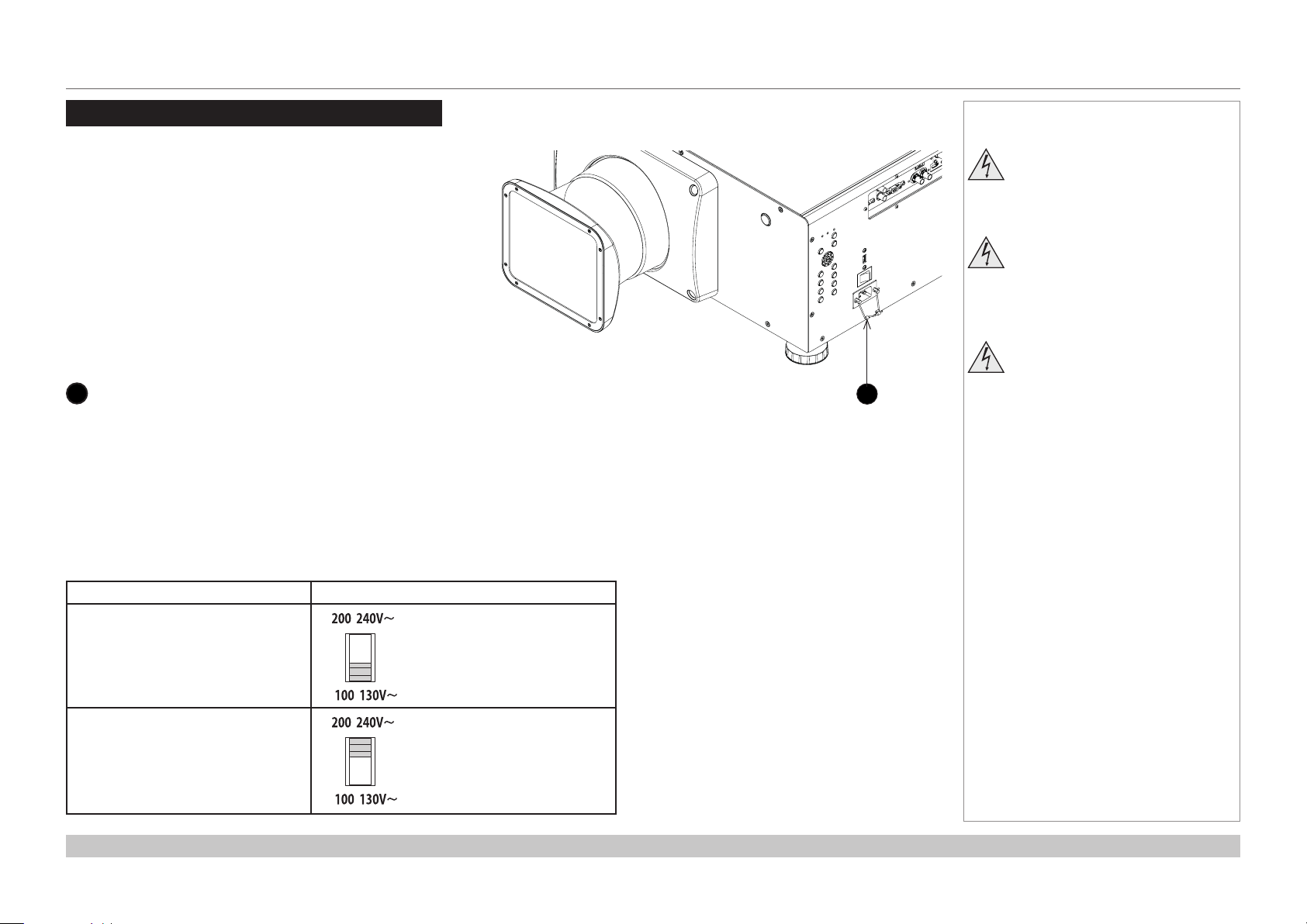
Connecting The Power Supply
Lift the cable lock up, push the mains connector in rmly and
push the lock down to secure the cable.
AC mains inlet with cable lock
1
Voltage selection
The VOLTAGE SELECT switch must be set to match the power supply you are using:
Notes
Use only the power cable
provided.
Ensure that the power outlet
includes a ground connection as
this equipment MUST be earthed.
Handle the power cable carefully
1
and avoid sharp bends. Do not
use a damaged power cable.
Voltage of power supply used Position of VOLTAGE SELECT switch
AC100V outlet
AC200V (single phase) outlet
Installation and Quick-Start Guide
Rev B December 2016
page 4
Page 13
Digital Projection HIGHlite Laser II 3D Series
PROJECTOR OVERVIEW
Projector Overview
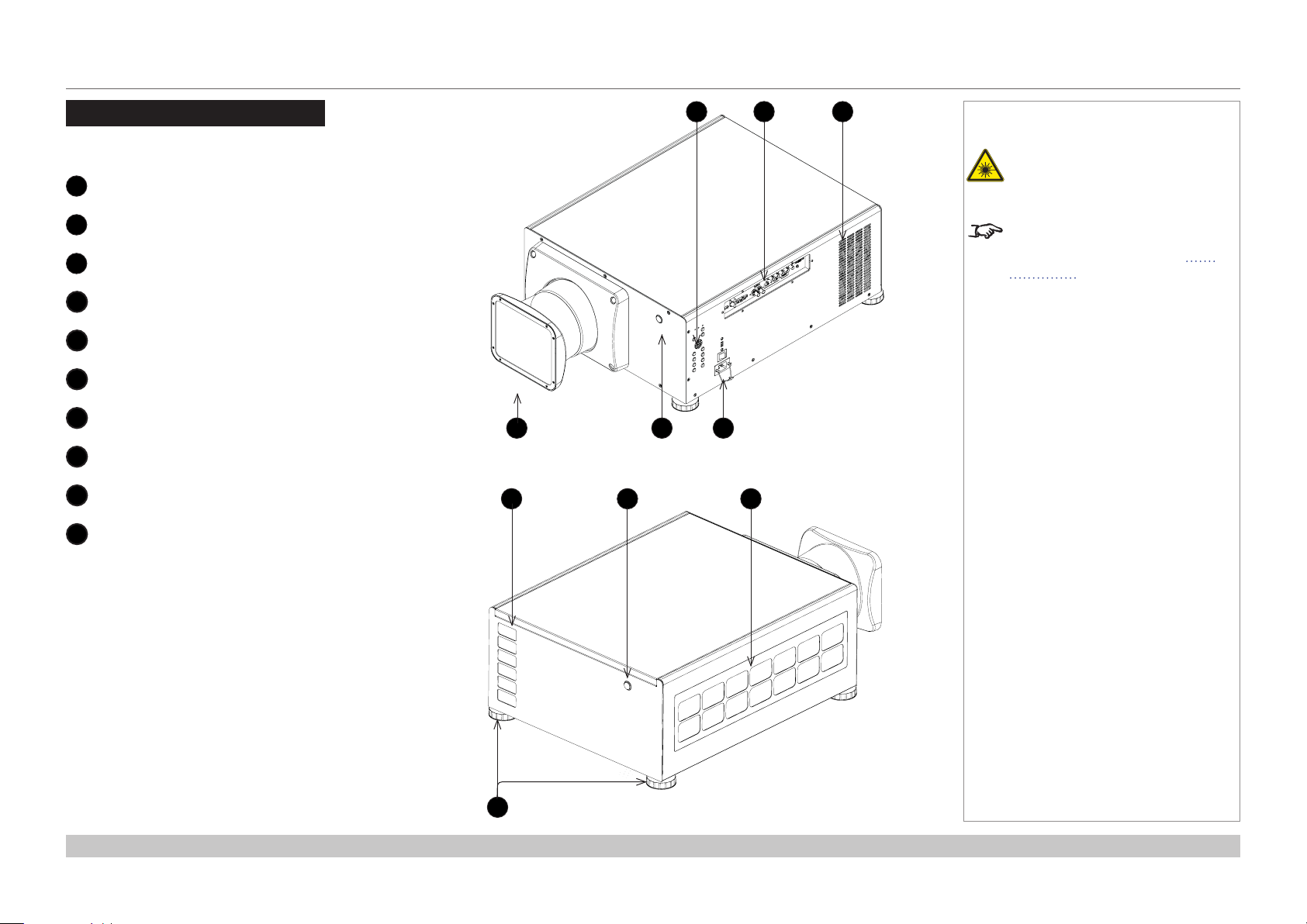
Front and rear views
Control panel
1
Connection panel
2
Air outlet
3
Lens hood
4
Front infrared window
5
Power switch and power connection
6
Air outlet
7
Rear infrared window
8
Air inlet
9
Adjustable feet
10
4 5
7 8
1
Front view
2
3
Notes
Do not use the short lens hood
with the 4.34 - 6.76 : 1 zoom lens.
For further information about using
the right lens and hood, see The
lens hood further in this guide.
6
9
Installation and Quick-Start Guide
10
Rear view
Rev B December 2016
page 5
Page 14
Digital Projection HIGHlite Laser II 3D Series
CONTROL PANEL
Control Panel
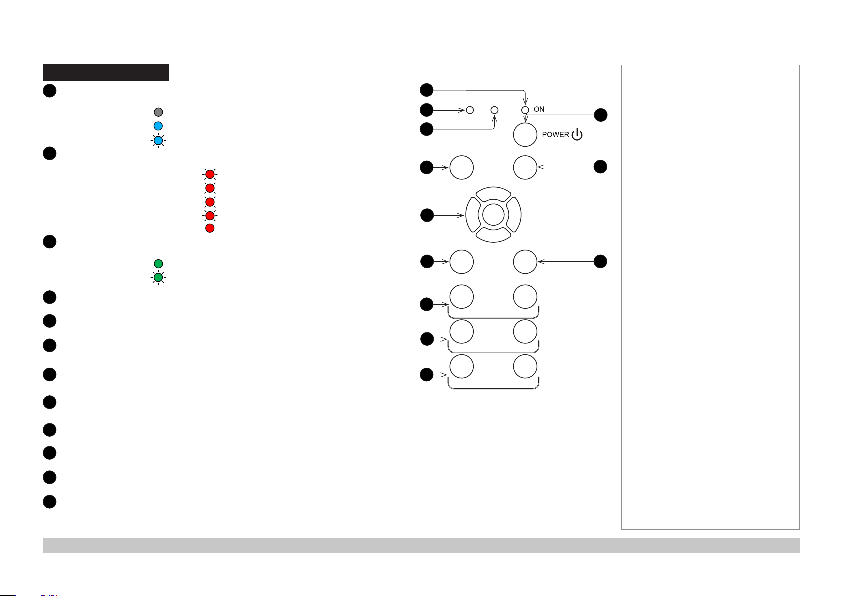
1
ON indicator (blue)
Behavior Meaning
Off The projector is switched off.
On The projector is switched ON.
Flashing The projector is warming up or cooling down.
2
ERROR indicator (red)
Behavior Meaning
Flash once, then pause Laser failure.
Flash twice, then pause Cover open.
Flash three times, then pause Fan failure.
Flash four times, then pause Over temperature.
On System error.
3
STANDBY indicator (green)
Behavior Meaning
On The projector is in STANDBY mode.
Flashing The projector is in STANDBY mode.
It can be switched on with a network command.
MENU button
4
Access the projector OSD (on-screen display).
5
Navigation (arrow buttons and ENTER)
Navigate the OSD and edit settings with the arrows, conrm choice with ENTER.
6
INPUT button
Select input source.
1
ERROR STANDBY
2
3
4
MENU
5
6
INPUT
7
OUT IN
8
OUT IN
Notes
10
11
EXIT
12
SHIFT
FOCUS
ZOOM
Focus IN / OUT
7
Adjust focus.
Zoom IN / OUT
8
Adjust zoom.
Shutter CLOSE / OPEN
9
Open and close the shutter.
10
POWER button
Switch the projector on and off (in STANDBY mode)
11
EXIT button
Close the OSD.
12
SHIFT button
Press and hold this button, then press the arrow buttons to move the lens.
Installation and Quick-Start Guide
9
CLOSE
SHUTTER
OPEN
Rev B December 2016
page 6
Page 15
Digital Projection HIGHlite Laser II 3D Series
REMOTE CONTROL
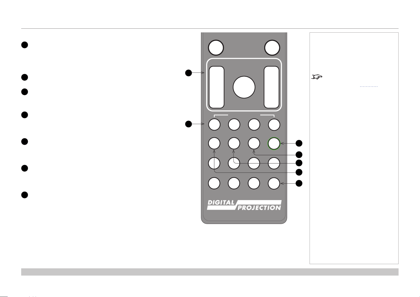
Remote Control
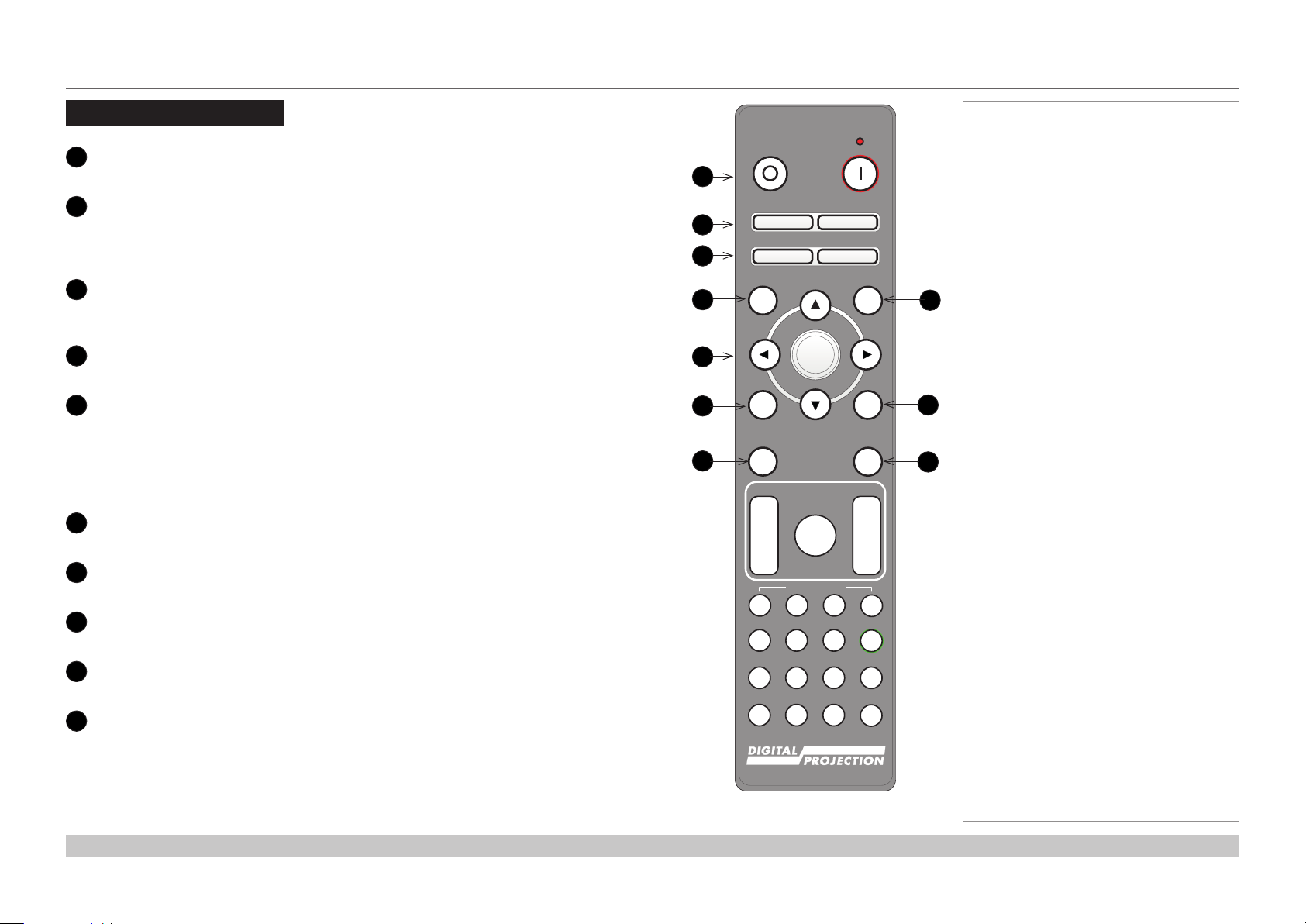
1
Power ON / OFF
Turns power on and off.
2
Pic Mute OPEN / CLOSE
Shows and hides the projected image.
When CLOSE is pressed, the light source switches off completely and the screen
becomes black.
2
OSD ON / OFF
Enable and disable screen timeout messages and control whether to show the OSD
during projection.
4
MENU
Access the OSD. If the OSD is open, press this button to go back to the previous menu.
5
Navigation (arrows and OK)
Navigate through the menus with the arrows, conrm your choice with OK.
In lens adjustment modes, the arrows are used to move, zoom or focus the lens. See 11
below.
In lens adjustment modes, or when the OSD is not showing, the OK button switches
between modes: Shift Adjustment and Zoom / Focus Adjustment.
6
EXIT
Go up one level in the OSD. When the top level is reached, press to close the OSD.
7
FREEZE
Freeze the current frame.
8
DEFAULT
When editing a parameter, press this button to restore the default value.
9
INFO
Access information about the projector.
10
RE-SYNC
Re-synchronise with the current input signal.
Notes
OFF ON
1
Pic Mute
2
3
4
5
6
7
OPEN CLOSE
OSD
OFF
MENU
ON
OK
EXIT INFO
FREEZE
FOCUS ZOOM
HDMI1
BRI
DISPLAYPORT
VGA COMP1 COMP2
3D EYE PIP SWAP
LENS
IN
SHIFT
OUT
USER PRESET
A B C D
HDMI2 DVI
21 3
CON GAMMA
HD-T 3GSDI
4 5 6
R G B ALL
7 8 9 0
DEFAULT
8
9
RE-SYNC
10
IN
OUT
ALT
ALT
ADDR
TEST
continues on next page...
Installation and Quick-Start Guide
Rev B December 2016
page 7
Page 16
MENU
EXIT INFO
OK
OSD
OFF
ON
DEFAULT
Digital Projection HIGHlite Laser II 3D Series
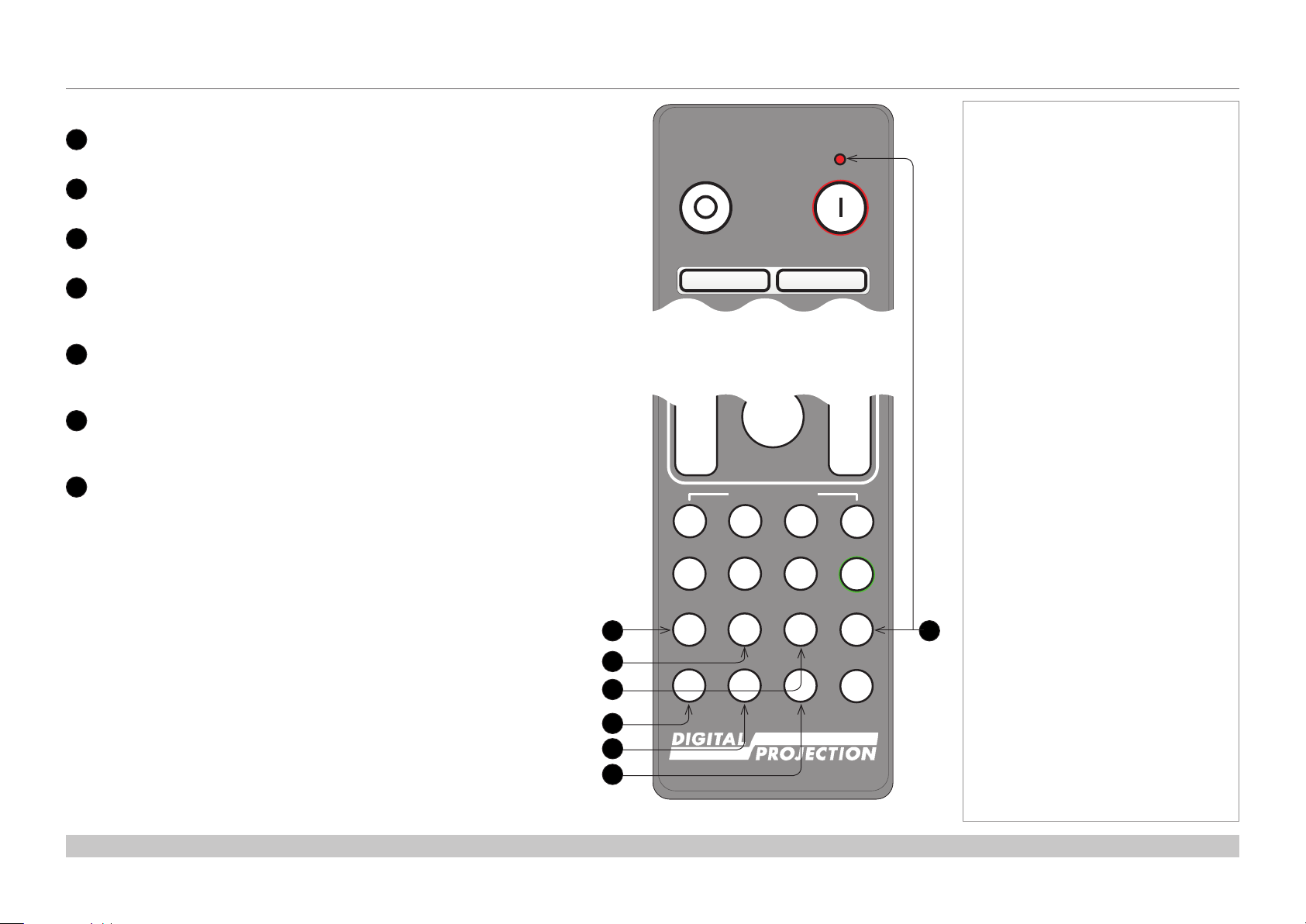
11
LENS adjustment
FOCUS IN / OUT: adjust focus.
SHIFT: press and hold this button, then use the Navigation arrow
buttons to move the lens.
ZOOM IN / OUT: adjust zoom.
12
USER PRESET A, B, C, D
Load user presets.
13
ALT
14
Press and hold this button to access alternative functions for all
buttons with a green label.
DVI / GAMMA / numeric input 3
Select the DVI input.
Use with ALT to switch to the next Gamma value:
...1.0, 1.8, 2.0, 2.2, 2.35, 2.5...
15
HDMI 2 / CON / numeric input 2
Select the HDMI 2 input.
Use with ALT to bring up the Contrast control, then adjust the value
with the LEFT and RIGHT arrow buttons.
16
HDMI 1 / BRI / numeric input 1
Select the HDMI 1 input.
Use with ALT to bring up the Brightness control, then adjust the
value with the LEFT and RIGHT arrow buttons.
17
TEST / SWAP / numeric input 0
Show a test pattern. Press again to show the next test pattern:
...Off, White, Black, Red, Green, Blue, CheckerBoard,
CrossHatch, V Burst, H Burst, ColorBar...
When PIP mode is on, use this button with ALT to swap the main and
sub images.
REMOTE CONTROL
FREEZE
FOCUS ZOOM
11
12
IN
OUT
A B C D
HDMI1
BRI
DISPLAYPORT
4 5 6
R G B ALL
VGA COMP1 COMP2
7 8 9 0
3D EYE PIP SWAP
LENS
SHIFT
USER PRESET
HDMI2 DVI
21 3
CON GAMMA
HD-T 3GSDI
RE-SYNC
IN
OUT
ALT
ALT
ADDR
TEST
Notes
For further information about
user presets, see Memory in the
Operating Guide.
13
14
15
16
17
continues on next page...
Installation and Quick-Start Guide
Remote control
Rev B December 2016
page 8
Page 17
Pic Mute
MENU
EXIT INFO
OK
LENS
FOCUS ZOOM
OSD
OFF
ON
DEFAULT
FREEZE
RE-SYNC
OPEN CLOSE
Digital Projection HIGHlite Laser II 3D Series
Select DisplayPort input.
17
DISPLAYPORT / R / numeric input 4
18
HD-T / G / numeric input 5
Select the HDBaseT input.
19
3GSDI / B / numeric input 6
Select the 3G-SDI input.
20
VGA / 3D / numeric input 7
Select the VGA input.
Use with ALT to toggle the 3D Format setting between Off and Auto.
21
COMP1 / EYE / numeric input 8
22
23
Select the Component 1 input.
Use with ALT to switch between left and right eye 3D dominance.
COMP2 / PIP / numeric input 9
Select the Component 2 input.
Use with ALT to switch on Picture In Picture (PIP) mode.
ADDR / ALL (with red indicator at the top)
Assign and unassign an IR remote address.
To assign an address:
1. Press and hold this button until the indicator starts ashing.
2. Release this button and while the indicator is still ashing, enter
a two-digit address using the numeric input buttons. The indicator
will ash three times quickly to conrm the change.
To unassign an address and return to the default address 00,
• Press and hold ALT and this button simultaneously until the
indicator ashes to conrm the change.
REMOTE CONTROL
OFF ON
Remote control top
IN
OUT
A B C D
HDMI1
BRI
DISPLAYPORT
17
18
19
20
21
22
4 5 6
R G B ALL
VGA COMP1 COMP2
7 8 9 0
3D EYE PIP SWAP
Pic Mute
OPEN CLOSE
OSD
SHIFT
USER PRESET
HDMI2 DVI
21 3
CON GAMMA
HD-T 3GSDI
Notes
IN
OUT
ALT
ALT
ADDR
23
TEST
Installation and Quick-Start Guide
Remote control bottom
Rev B December 2016
page 9
Page 18
Digital Projection HIGHlite Laser II 3D Series
REMOTE CONTROL
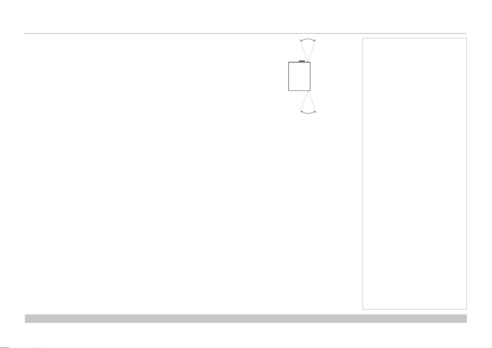
Infrared reception
The projector has infrared sensors at the front and back.
The angle of acceptance is 40°. Make sure that the remote control is within the angle of
acceptance when trying to control the projector.
40°
40°
Infrared reception
Notes
Installation and Quick-Start Guide
Rev B December 2016
page 10
Page 19
Digital Projection HIGHlite Laser II 3D Series
POSITIONING THE SCREEN AND PROJECTOR
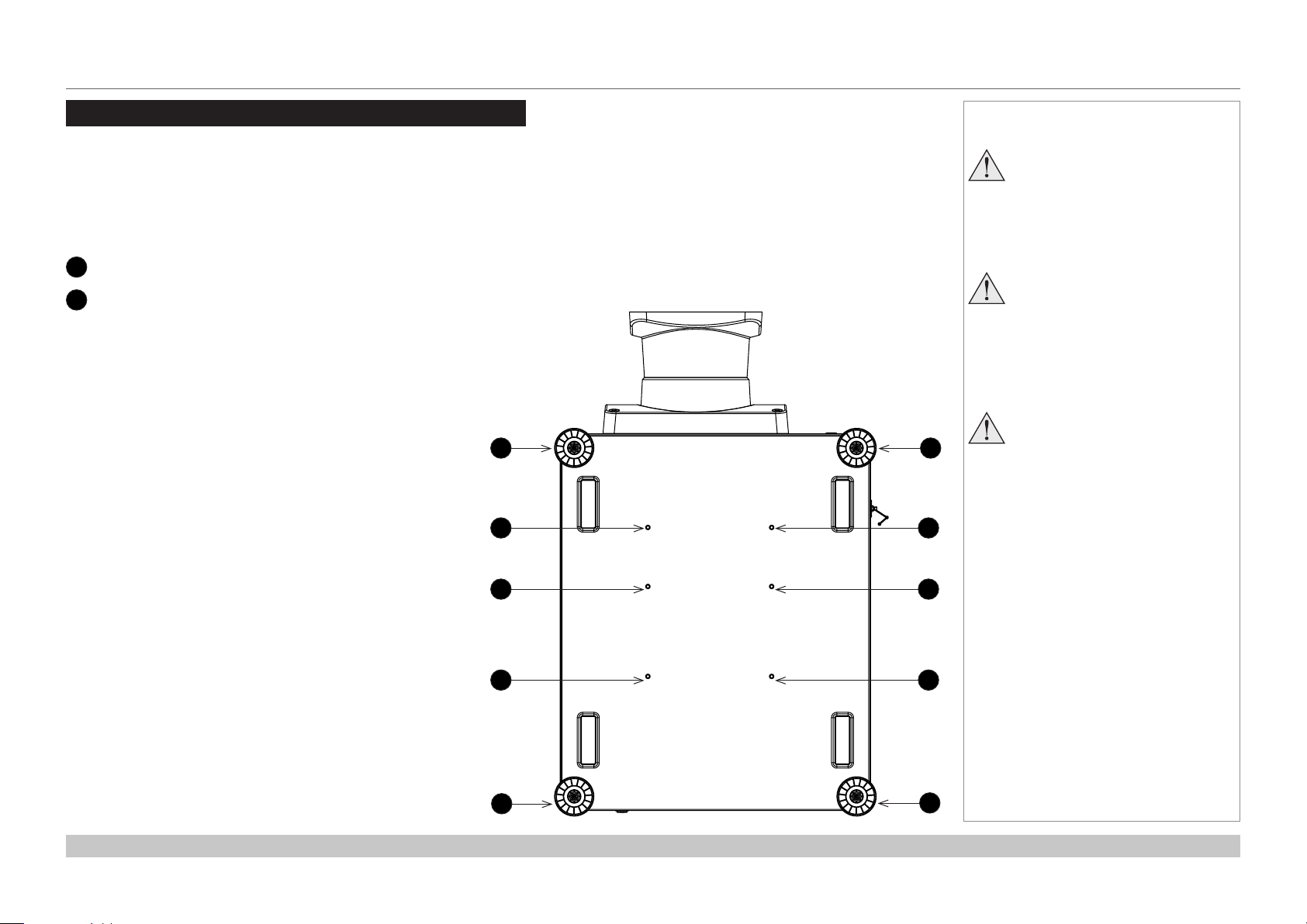
Positioning The Screen And Projector
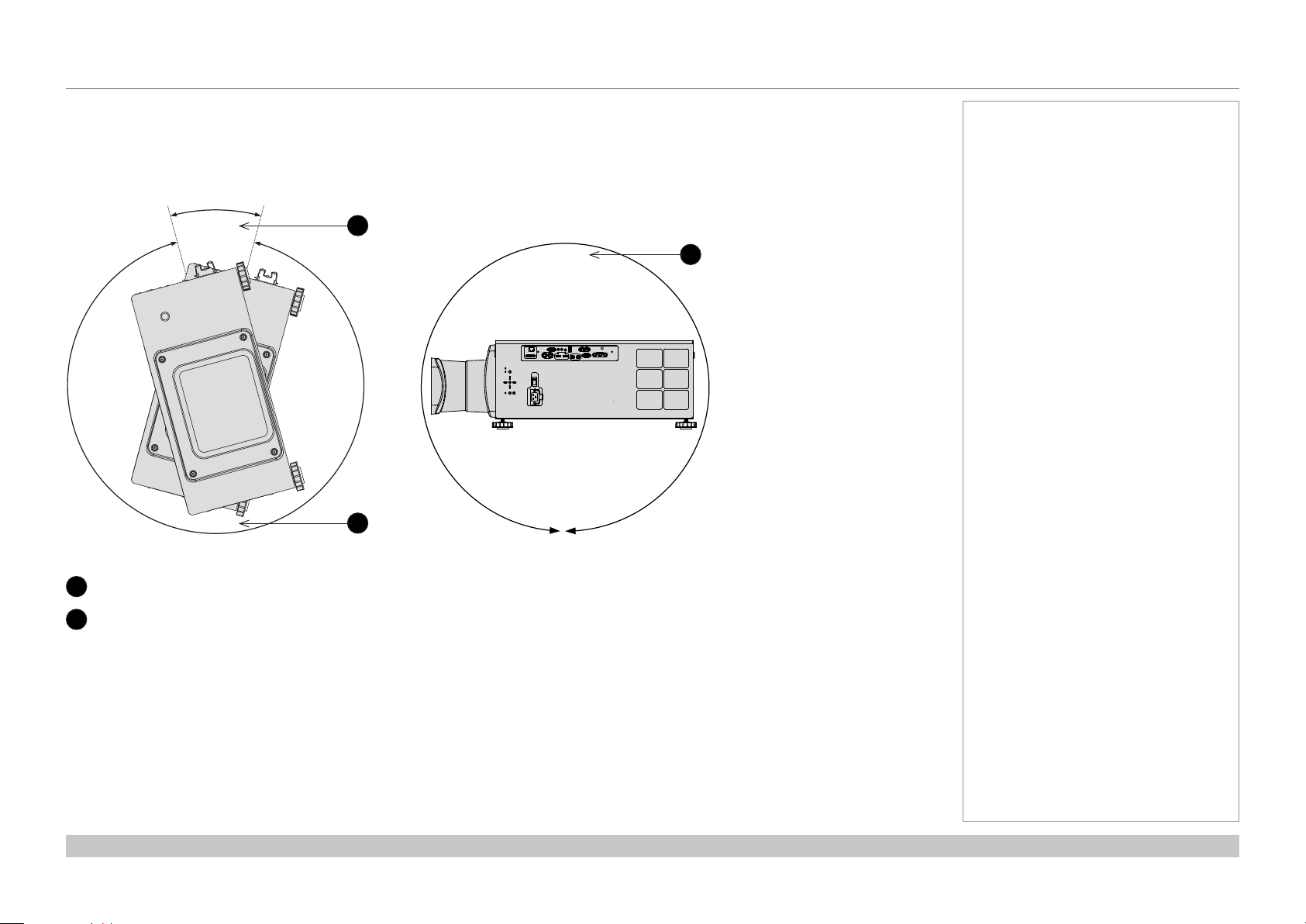
1. Install the screen, ensuring that it is in the best position for viewing by your audience.
2. Mount the projector, ensuring that it is at a suitable distance from the screen for the image to ll the screen. Set the adjustable feet so that
the projector is level, and perpendicular to the screen.
The drawing below shows the positions of the feet for table mounting, and the xing holes for ceiling mounting.
1
Four adjustable feet
2
Six M6 holes for ceiling mount
The screws should not penetrate more than 15 mm into
the body of the projector.
1
2
1
2
Notes
Always allow the projector
to cool for 5 minutes before
disconnecting the power or
moving the projector.
Ensure that there is at least 50
cm (20 in) of space between the
ventilation outlets and any wall,
and 30 cm (12 in) on all other
sides.
Do not stack more than 3
projectors.
Installation and Quick-Start Guide
2
2
1
2
2
1
Rev B December 2016
page 11
Page 20
Digital Projection HIGHlite Laser II 3D Series
POSITIONING THE SCREEN AND PROJECTOR
Roll and pitch
The projector can be operated in numerous positions.
It is not recommended to position the projector in portrait mode with inputs facing upward, as shown in the diagram.
30°
330°
1
360°
2
2
Notes
Roll
1
Positions to avoid: inputs side up
2
Recommended positions
Installation and Quick-Start Guide
Pitch
Rev B December 2016
page 12
Page 21
Digital Projection HIGHlite Laser II 3D Series
CHANGING THE LENS
Changing The Lens
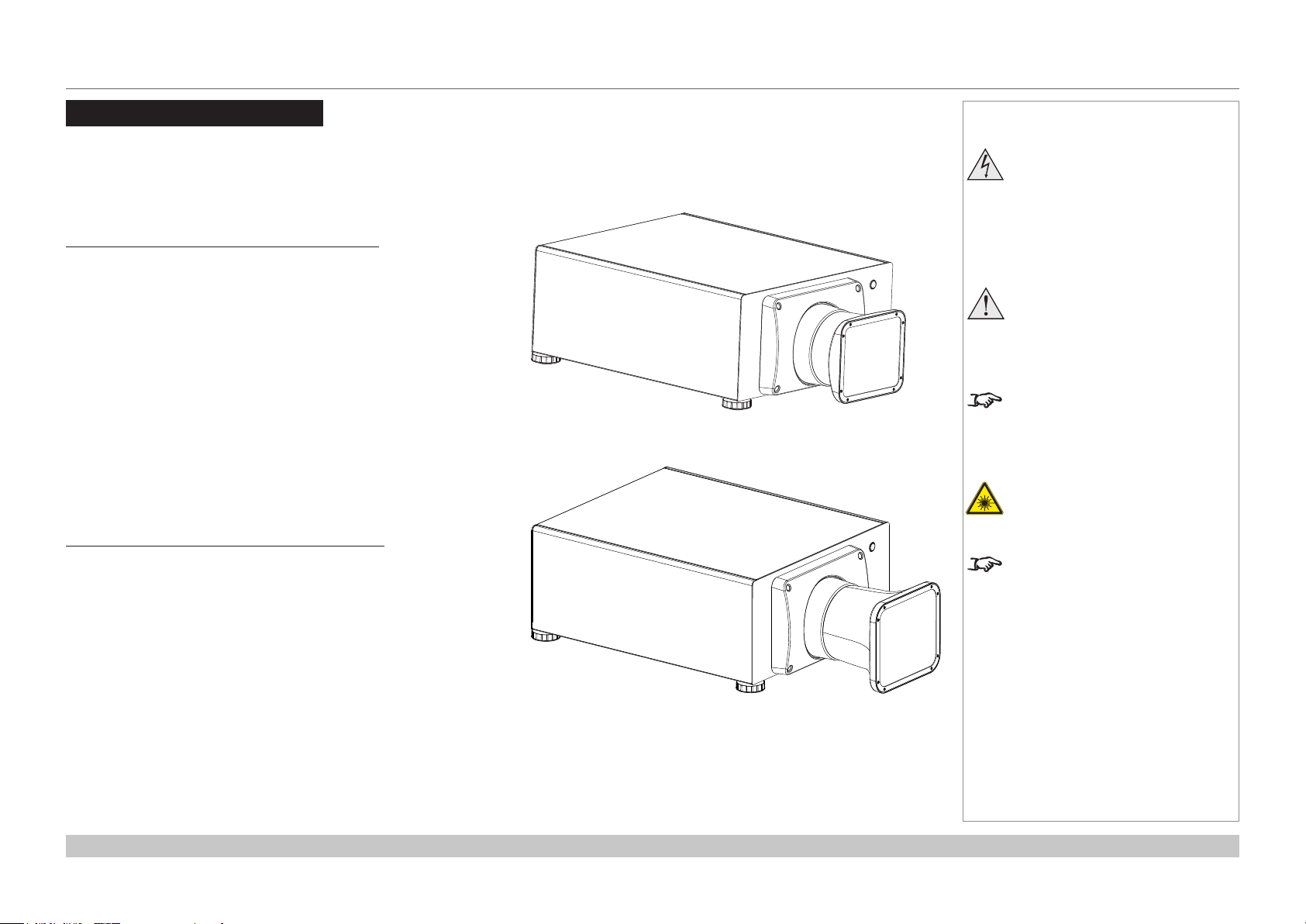
The lens hood
There are two types of lens hood, short and long.
The short lens hood is used with the following lenses:
Throw ratios Part number
0.77 : 1 xed lens 110-808
1.16 : 1 xed lens 110-809
1.45 - 1.74 : 1 zoom lens 110-803
1.74 - 2.17 : 1 zoom lens 112-878
2.17 - 2.90 : 1 zoom lens 113-852
2.90 - 4.34 : 1 zoom lens 110-806
The long lens hood must be used with the following long throw lens:
Throw ratios Part number
4.34 - 6.76 : 1 zoom lens 110-807
Projector with short lens hood tted
Notes
Before changing the lens,
always make sure the projector
is switched off and fully
disconnected from its power
supply.
When changing the lens, avoid
using excessive force as this may
damage the equipment.
Take care to preserve the original
lens packaging and protective caps
for future use.
Do not use the short lens hood
with the 4.34 - 6.76 : 1 zoom lens.
The projector will not power on
without the lens and lens hood tted.
Installation and Quick-Start Guide
Projector with long lens hood tted
Rev B December 2016
page 13
Page 22
Digital Projection HIGHlite Laser II 3D Series
CHANGING THE LENS
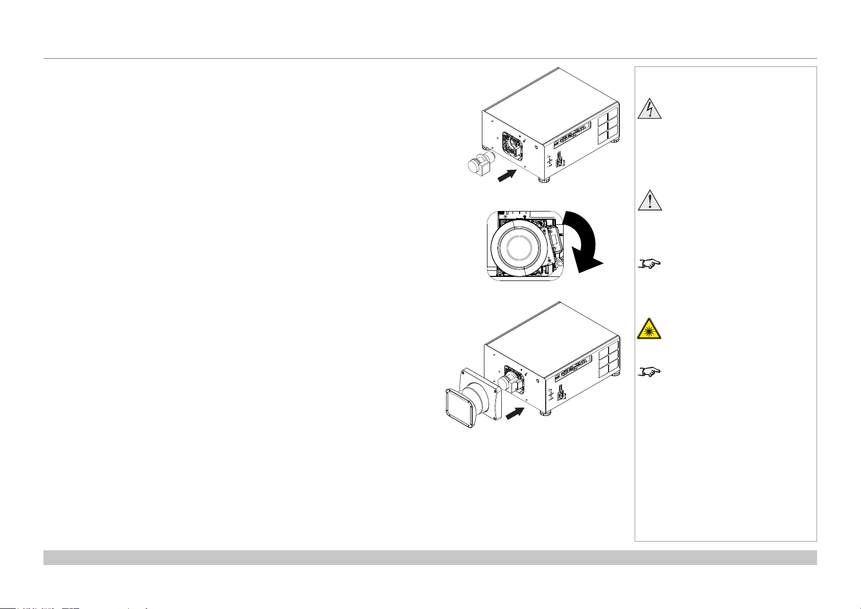
Inserting a new lens
1. Insert the lens into the lens aperture, making sure that the plug on the zoom drive
mechanism lines up with socket on the right of the lens aperture.
2. Rotate the lens clockwise until it clicks into place.
Notes
Before changing the lens,
always make sure the projector
is switched off and fully
disconnected from its power
supply.
When changing the lens, avoid
using excessive force as this may
damage the equipment.
Take care to preserve the original
lens packaging and protective caps
for future use.
Do not use the short lens hood
with the 4.34 - 6.76 : 1 zoom lens.
3. Secure the lens hood to the front of the projector with the screws.
Installation and Quick-Start Guide
The projector will not power on
without the lens and lens hood tted.
Rev B December 2016
page 14
Page 23
Digital Projection HIGHlite Laser II 3D Series
CHANGING THE LENS
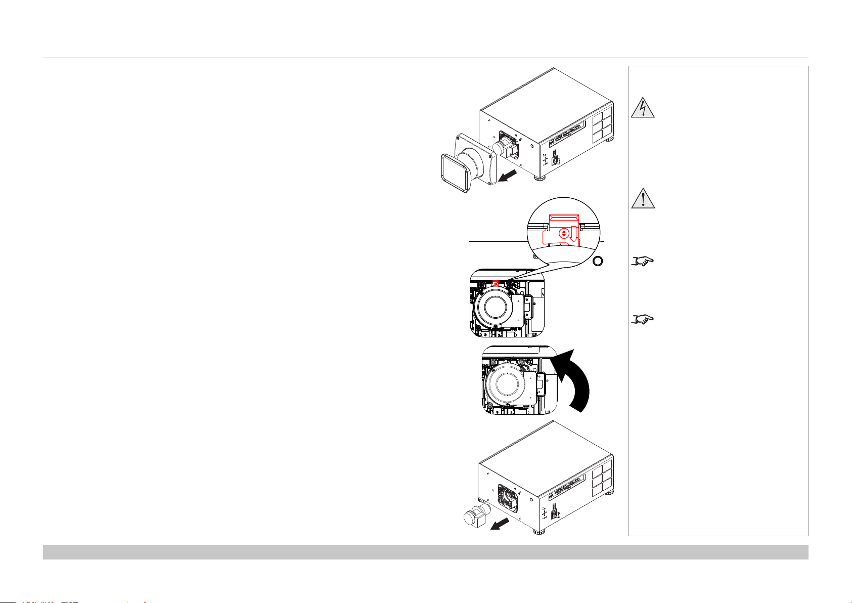
Removing the lens
1. Loosen the four screws securing the lens hood to the body of the projector.
Remove the lens hood.
2. Push down the lens holder tab.
Notes
Before changing the lens,
always make sure the projector
is switched off and fully
disconnected from its power
supply.
When changing the lens, avoid
using excessive force as this may
damage the equipment.
Take care to preserve the original
lens packaging and protective caps
for future use.
The projector will not power on
without the lens and lens hood tted.
3. Rotate the lens anti-clockwise.
4. Pull the lens forward to remove it from the lens aperture.
Installation and Quick-Start Guide
Rev B December 2016
page 15
Page 24
Digital Projection HIGHlite Laser II 3D Series
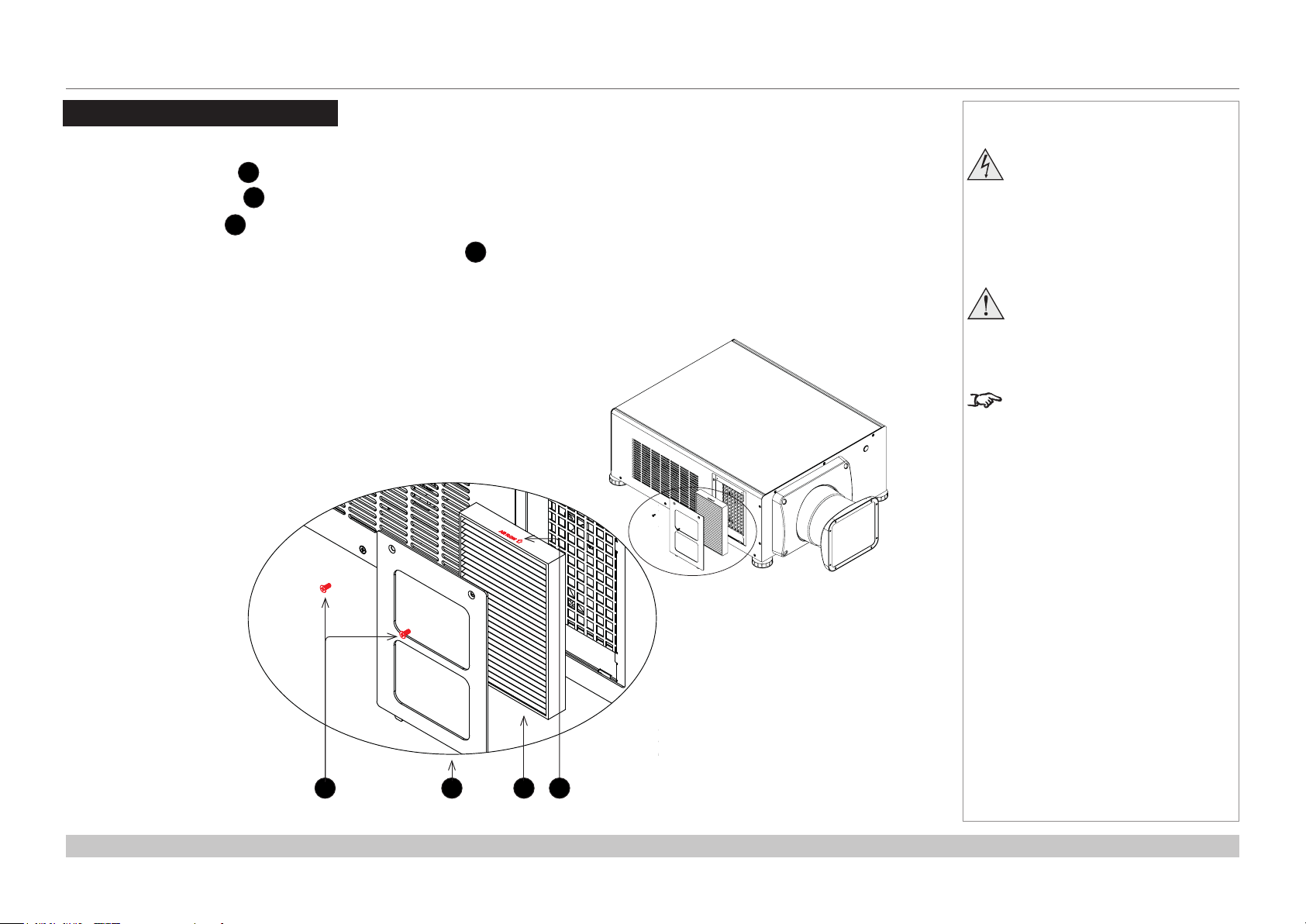
CHANGING THE FILTERS
Changing The Filters
1. Remove the two screws 1 holding the lter cover.
2. Remove the lter cover 2.
3. Remove the old lter 3.
4. Place the new lter in the slot. Make sure the air ow arrow 4 points toward the projector, as shown in the illustration.
5. Replace the lter cover and tighten the screws.
Notes
Beforechangingthelters,
always make sure the projector
is switched off and fully
disconnected from its power
supply.
Whenchangingthelters,avoid
using excessive force as this may
damage the equipment.
In a normal environment the lters
should be changed every 2000
hours.
Installation and Quick-Start Guide
1
2
4
3
Rev B December 2016
page 16
Page 25
Digital Projection HIGHlite Laser II 3D Series
OPERATING THE PROJECTOR
Operating The Projector
Switching the projector on
1. Ensure a lens is tted. Connect the power cable between the mains supply and the projector. (See Connecting the power supply
above.) Switch on at the switch next to the power connector.
2. The POWER indicator lights red to signal that the projector is in STANDBY mode. Press one of the following buttons:
• On the remote control, the ON button
• On the projector control panel, the POWER button.
The fans begin working, then the POWER indicator begins ashing green. When the ashing stops, the POWER and LIGHT indicators
both light steady green. The projector is switched on.
Switching the projector off
1. Press OFF on the remote control or POWER on the control panel, then press again to conrm your choice.
The POWER indicator on the control panel will start ashing amber, the system will go out and the cooling fans will run for a short time
until the POWER indicator goes stready red to indicate that the projector has entered STANDBY mode.
2. If you need to switch the projector off completely, switch off at the mains power switch next to the power connector and then disconnect
the power cable from the projector.
Notes
See also Connecting The Power
Supply earlier in this guide.
The self-test is running when all the
LEDs on the control panel are lit.
Use only the power cable
provided.
Ensure that the power outlet
includes a ground connection as
this equipment MUST be earthed.
Handle the power cable carefully
and avoid sharp bends. Do not
use a damaged power cable.
Installation and Quick-Start Guide
Rev B December 2016
page 17
Page 26
Digital Projection HIGHlite Laser II 3D Series
OPERATING THE PROJECTOR
Selecting an input signal
1. Connect one or more image sources to the projector.
2. Select the input you want to display:
• Press one of the input buttons on the remote control.
• Alternatively, open the On-screen display (OSD) by pressing MENU. Highlight Input from the main menu, press ENTER/OK and then
select an input signal using the UP and DOWN arrow buttons. Press ENTER/OK to conrm your choice.
Selecting a test pattern
To display a test pattern:
• Press TEST on the remote control.
Change the test pattern using the LEFT and RIGHT arrow buttons.Test patterns are displayed in the following order:
White, Black, Red, Green, Blue, CheckerBoard, CrossHatch, V Burst, H Burst, ColorBar, Screen Layout, Off
• Alternatively, open the OSD by pressing MENU. Highlight Test Patterns from the main menu, then select a test pattern using the LEFT
and RIGHT arrow buttons.
After the nal test pattern, the projector exits test pattern mode and returns to the main image. To view test patterns again, you need to press
TEST again. If you wish to exit the test patterns before you reach the nal one,
• press TEST or EXIT at any time.
Notes
For full details of how to use the
controls and the menu system, see
the Operating Guide.
Installation and Quick-Start Guide
Rev B December 2016
page 18
Page 27

Digital Projection HIGHlite Laser II 3D Series
OPERATING THE PROJECTOR
Adjusting the lens
The lens can be adjusted using the Lens menu, or using the lens buttons on the remote control.
Lens menu
The Lens menu provides access to the Lens Control setting and the Lens Center command.
Lens Control allows Zoom, Focus and Shift adjustment using the arrow buttons. The setting operates in Zoom/Focus Adjustment and
Shift Adjustment mode.
Press ENTER/SELECT to switch between the two modes.
Remote control
Use the remote control to adjust zoom, focus and shift directly, without opening a menu:
• OK enters lens control, then switches between Zoom/Focus Adjustment and Shift Adjustment.
• EXIT exits lens control and opens the Lens menu.
• MENU exits lens control and returns to the main image.
• The arrow buttons adjust zoom, focus and shift as indicated on the screen.
Adjusting the image
Orientation
• This can be set from the Setup menu.
Highlight Orientation and choose from Front Tabletop, Front Ceiling, Rear Tabletop, Rear Ceiling and Auto-front.
Notes
When adjusting focus and zoom,
you may nd it useful to display
the CrossHatch test pattern: press
TEST on the remote control and
navigate through the list of patterns
using the LEFT and RIGHT
arrow buttons.
For full details of how to adjust
the lens using the remote control,
see Remote Control earlier in this
guide.
Setup menu
Keystone
• This can be set from the Geometry menu.
Picture
• Settings such as Gamma, Brightness, Contrast, Saturation, Hue and Sharpness can be set from the Image menu.
Installation and Quick-Start Guide
Geometry menu
Image menu
Rev B December 2016
page 19
Page 28

Digital Projection HIGHlite Laser II 3D Series
This page is intentionally left blank.
Installation and Quick-Start Guide
Page 29
HIGHlite Laser II 3D Series
High Brightness Digital Video Projector
4
CONNECTION GUIDE
Rev B December 2016
Page 30

Digital Projection HIGHlite Laser II 3D Series
IN THIS GUIDE
IN THIS GUIDE
Signal Inputs ....................................................................................................... 23
Digital inputs and outputs ........................................................................................23
Analog inputs and outputs .......................................................................................24
EDID on the HDMI, DisplayPort and VGA inputs ....................................................25
Using HDMI/DisplayPort switchers with the projector ..........................................25
3D connections .........................................................................................................26
3D sources up to 60Hz requiring frame doubling and left/right interleaving ...................26
Frame sequential 3D sources up to 120Hz .....................................................................26
Dual Pipe 3D ...................................................................................................................26
3D Sync ......................................................................................................................27
3D Sync in .......................................................................................................................27
3D Sync out ....................................................................................................................27
Control Connections ........................................................................................ 28
LAN connection examples .......................................................................................29
RS232 connection example ......................................................................................30
Connection Guide
Rev B December 2016
Page 31

Digital Projection HIGHlite Laser II 3D Series
SIGNAL INPUTS
Signal Inputs
Digital inputs and outputs
HDBaseT
1
Receives digital signal from HDBaseT-compliant devices.
3G-SDI in
2
3G-SDI out
3
Connect a 3G-SDI cable to distribute the 3G-SDI signal to another projector.
HDMI I
4
HDMI 1.4a input. Connect an HDMI cable to the connector.
HDMI II
5
HDMI 1.4a input. Connect an HDMI cable to the connector.
DisplayPort
6
DisplayPort 1.1a input. Connect a DisplayPort cable to the connector.
Supports sources up to 1920x1200 resolution, 24-120 Hz. Supports HDCP.
Notes
For simultaneous HDBaseT and
LAN connectivity, a third-party
distribution product can be utilised
to combine HDBaseT video stream
with LAN connection for delivery to
the projector.
The projector can receive
100/120Hz and display 3D at
100/120Hz.
For a complete listing of all
supported signal input modes, see
Appendix C: Supported Signal
Input Modes in the Reference
Guide.
For a complete listing of pin
congurations for all signal and
1
control connectors, see Appendix
E: Wiring Details in the Reference
Guide.
Connection Guide
2 3
4 5 6
Rev B December 2016
page 23
Page 32

Digital Projection HIGHlite Laser II 3D Series
SIGNAL INPUTS
Analog inputs and outputs
1
Component
RGBHV, RGsB or RGBS
• Set Color Space in the Color menu to Auto or RGB-Video.
YPbPr or YCbCr
Set Color Space in the Color menu to Auto, YPbPr or YCbCr.
2
VGA
This input receives analog signals from a computer. When using this input, it is best to use a fully wired VGA cable to connect the
source to the projector. This will allow the source to determine the projector’s capabilities via DDC and show an optimized image.
Such cables can be identied as they have a blue connector shell.
Notes
For a complete listing of all
supported signal input modes, see
Appendix C: Supported Signal
Input Modes in the Reference
Guide.
For a complete listing of pin
congurations for all signal and
control connectors, see Appendix
E: Wiring Details in the Reference
Guide.
1 2
Connection Guide
Rev B December 2016
page 24
Page 33

Digital Projection HIGHlite Laser II 3D Series
SIGNAL INPUTS
EDID on the HDMI, DisplayPort and VGA inputs
If you are using a computer graphics card or another source that obeys the EDID protocol, the source will automatically congure itself to suit
the projector.
Otherwise refer to the documentation supplied with the source to manually set the resolution to the DMD™ resolution of the projector or the
nearest suitable setting. Switch off the source, connect to the projector, then switch the source back on again.
Using HDMI/DisplayPort switchers with the projector
When using an HDMI/DisplayPort source switcher with the projector, it is important to set the switcher so that it passes the projector EDID
through to the source devices. If this is not done, the projector may not be able to lock to the source or display the source correctly as its
video output timings may not be compatible with those of the projector. Sometimes this is called transparent, pass-through or clone mode.
See your switcher’s manual for information on how to set this mode.
Additionally, sources which use HDCP encryption may not display properly when connected to the projector via a switcher. Refer to the
switcher’s manual for more information.
1 32
1
Sources
2
Switcher
3
Projector
EDID
EDID
EDID
EDID
Notes
Connection Guide
The EDIDs in the switcher should be the same as the one in the projector.
Rev B December 2016
page 25
Page 34

Digital Projection HIGHlite Laser II 3D Series
SIGNAL INPUTS
3D connections
3D sources up to 60Hz requiring frame doubling and left/right interleaving
1. Connect to either of the following inputs on the connection panel:
• HDMI 1
• HDMI 2
• HDBaseT
2. Set 3D Format in the 3D menu to match the format of the incoming signal. Choose from Auto, Side by Side (Half) and
Top and Bottom.
The Frame Packing format is automatically detected by the projector.
Frame sequential 3D sources up to 120Hz
• Connect to the DisplayPort input.
The Frame Sequential format is automatically detected by the projector and is supported on the DisplayPort input only.
Dual Pipe 3D
1. Connect the left eye output to the HDMI 1 socket and the right eye output to the HDMI 2 socket.
2. Set 3D Format in the 3D menu to Dual-Pipe.
1
Notes
For a complete listing of all
supported signal input modes, see
Appendix C: Supported Signal
Input Modes in the Reference
Guide.
For a complete listing of pin
congurations for all signal and
control connectors, see Appendix
E: Wiring Details in the Reference
Guide.
Connection Guide
1
HDBaseT
2
HDMI 1 / Dual Pipe LEFT
3
HDMI 2 / Dual Pipe RIGHT
4
DisplayPort
2 3 4
Rev B December 2016
page 26
Page 35

Digital Projection HIGHlite Laser II 3D Series
SIGNAL INPUTS
3D Sync
3D Sync in
Sync input signal – normally only required for Sequential 3D
sources.
• Connect the 3D sync from your graphics card or server.
3D Sync out
Sync output signal. This may be affected by the Sync Offset
setting in the 3D Control menu.
Connect this to your IR emitter or ZScreen.
Notes
For a complete listing of pin
congurations for all signal and
control connectors, see Appendix
E: Wiring Details in the Reference
Guide.
1
2
1
Sync In
2
Sync Out
5
43
The projector can be used with
active 3D glasses. Passive 3D
glasses such as polarized and split
wavelength glasses cannot be used
with this projector.
Connection Guide
6
3
3D input
4
3D Sync In
5
3D Sync Out
6
IR emitter or ZScreen
Rev B December 2016
page 27
Page 36

Digital Projection HIGHlite Laser II 3D Series
CONTROL CONNECTIONS
Control Connections
LAN
1
• All of the projector’s features can be controlled via a
LAN connection, using commands described in the
Protocol Guide.
• Use a crossed LAN cable to connect directly to a
computer, or an uncrossed cable to connect to a
network hub.
This connection is also used by the HDbBaseT input.
Trigger 1 & Trigger 2
2
The Trigger outputs are activated by one of the three
following conditions, as set in the Setup menu:
• Screen trigger: can be connected to an electrically
operated screen, automatically deploying the
screen when the projector starts up, and retracting
the screen when the projector shuts down.
• Aspect ratio trigger: can be used to control screen
shuttering for different aspect ratios.
• RS232 trigger: can be used to control the screen or
screen shuttering on receipt of an RS232 command
RS232
3
• All of the projector’s features can be controlled via a
serial connection, using commands described in the
Protocol Guide.
• Use a straight-through cable to connect directly to a
computer.
Wired Remote
4
The remote control can be connected using a standard
TRS cable.
2 3 4
Control connections
Notes
1
For simultaneous HDBaseT and
LAN connectivity, a third-party
distribution product can be utilised
to combine HDBaseT video stream
with LAN connection for delivery to
the projector.
For a list of all commands used to
control the projector via LAN, see
the Protocol Guide.
For a complete listing of pin
congurations for all signal and
control connectors, see Appendix
E: Wiring Details in the Reference
Guide.
Only one remote connection (RS232
or LAN) should be used at any one
time.
Connection Guide
Rev B December 2016
page 28
Page 37

Digital Projection HIGHlite Laser II 3D Series
CONTROL CONNECTIONS
LAN connection examples
The projector’s features can be controlled via a LAN connection, using Digital Projection’s Projector Controller application or a terminalemulation program.
Crossed
LAN cable
Computer
Un-crossed LAN cables
Projector
Computer
1
Notes
Projector Controller is available for
download, free of charge, from the
Digital Projection website.
Hub or LAN
Connection Guide
Projector
Projector
1
LAN
Rev B December 2016
page 29
Page 38

Digital Projection HIGHlite Laser II 3D Series
CONTROL CONNECTIONS
RS232 connection example
Straight-through
Computer
1
Notes
cable
Projector
Connection Guide
1
RS232
Rev B December 2016
page 30
Page 39

HIGHlite Laser II 3D Series
High Brightness Digital Video Projector
4
OPERATING GUIDE
Rev B December 2016
Page 40

Digital Projection HIGHlite Laser II 3D Series
IN THIS GUIDE
IN THIS GUIDE
Using The Menus ............................................................................................... 33
Opening the OSD ......................................................................................................33
Opening a menu ........................................................................................................33
Exiting menus and closing the OSD .......................................................................33
Inside a menu ............................................................................................................34
Accessing sub-menus .....................................................................................................34
Executing commands ......................................................................................................34
Editing projector settings .........................................................................................35
Using a slider to set a value ............................................................................................35
Editing numeric values ....................................................................................................35
Using The Projector ......................................................................................... 36
Main menu .................................................................................................................36
Lens menu .................................................................................................................37
Lens Control ....................................................................................................................37
Lens Memory ..................................................................................................................38
Image menu ...............................................................................................................39
Noise Reduction ..............................................................................................................40
Position and Phase .........................................................................................................40
Color menu ................................................................................................................41
Color Space ....................................................................................................................41
Color Mode .....................................................................................................................42
Geometry menu .........................................................................................................47
Aspect Ratio ....................................................................................................................47
Digital Zoom & Shift ........................................................................................................49
Overscan .........................................................................................................................50
Blanking ..........................................................................................................................51
Keystone .........................................................................................................................52
4 Corners ........................................................................................................................54
Rotation ...........................................................................................................................55
Pincushion / Barrel ..........................................................................................................56
Edge Blend menu ......................................................................................................57
Blend Width .....................................................................................................................58
Black Level Uplift ............................................................................................................59
3D menu .....................................................................................................................60
3D types ..........................................................................................................................61
Some 3D settings explained ...........................................................................................62
Frame rate multiplication in 3D images ...........................................................................63
Laser menu ................................................................................................................64
Setup menu ................................................................................................................65
ColorMax Setting ............................................................................................................67
Power On/Off ..................................................................................................................68
Clock Adjust ....................................................................................................................69
OSD Settings ..................................................................................................................70
Memory ...........................................................................................................................70
Network menu ...........................................................................................................71
PIP menu ....................................................................................................................72
Information menu ......................................................................................................73
Signal Format ..................................................................................................................73
System Status .................................................................................................................74
Thermal Status ................................................................................................................74
Factory Reset ..................................................................................................................75
Possible Combinations Of Settings ............................................................ 76
Operating Guide
Rev B December 2016
Page 41

Digital Projection HIGHlite Laser II 3D Series
USING THE MENUS
Using The Menus
Opening the OSD
Access the various menus using
either the projector control panel or
the remote control. On either device,
• press the MENU button.
The on-screen display (OSD) opens
showing the list of available menus.
Opening a menu
Move up and down the list using the
UP and DOWN arrow buttons.
To open a menu,
• press ENTER on the control
panel or OK on the remote
control.
This guide refers to the above two
buttons as ENTER/OK.
Exiting menus and closing the OSD
To go back to the previous page,
• press EXIT.
When you reach the top level,
pressing EXIT will close the OSD.
To close the OSD from any page,
• press MENU.
POWER
Input
Test Pattern
Lens
Image
Color
Geometry
Edge Blend
3D
Laser
Setup
Network
INPUT
AUTO
SYNC
ASPECT
CENTER
LENS
PIC MUTE
Projector control panel
Main Menu
HDMI 1
PIP
u
u
u
u
u
u
u
u
u
q
Information
On-screen display (OSD): top level menus
OFF ON
OPEN CLOSE
OFF
MENU
EXIT INFO
Remote control
Main Menu
p
Notes
Pic Mute
OSD
ON
DEFAULT
OK
u
u
Operating Guide
Rev B December 2016
page 33
Page 42

Digital Projection HIGHlite Laser II 3D Series
USING THE MENUS
Inside a menu
When you open a menu, the page consists of the following elements:
• Title bar at the top
Shows which menu you have accessed.
• Highlighted item
• Available and unavailable items
Unavailable items appear a pale gray color. Whether an item is available may
depend on other settings.
• The text or symbol to the right of an item shows whether the item:
• has a value that can be changed (the current value is shown)
• opens a sub-menu (an arrow button is displayed)
• executes a command (the space to the right of the item is blank).
Accessing sub-menus
Use the UP and DOWN arrow buttons to highlight the sub-menu, then press
ENTER/OK.
Executing commands
If the item contains a command, highlighting it reveals an OK button.
Press ENTER/OK to execute the highlighted command.
Color >>
Color Space
Color Temperature
Color Gamut
User Gamut
Red Lift
Green Lift
Blue Lift
Red Gain 100
Green Gain
Blue Gain
Highlighted Item
Menu Item
Unavailable Item
Slider
Sub-menu
Command
Select Item
Menu Name
Value
Adjust
Value
Value
Native
Value
Native
[Menu] Return
Auto
100
100
100
100
100
Inside a menu
Menu Name
Menu Item Value
Highlighted Command
OK
Notes
The highlighted item has green
background.
u
You may be asked for conrmation. Use the ENTER/OK to conrm, or EXIT to cancel.
Operating Guide
Highlighted command
Command Name
WARNING
All [Menu] values will be lost.
Press OK to confirm
Press Exit to cancel
Conrmation dialog
Rev B December 2016
page 34
Page 43

Digital Projection HIGHlite Laser II 3D Series
USING THE MENUS
Editing projector settings
If the highlighted menu item contains a list of values to choose from, you can
change the value by doing the following:
1. Highlight the menu item and press ENTER/OK.
2. In the list of values that opens, use the UP and DOWN arrow buttons to
highlight a value, then press ENTER/OK again to select the highlighted value.
Using a slider to set a value
Some parameters open a slider. To set such a parameter:
1. Press the LEFT or RIGHT arrow button, or ENTER/OK.
The arrow buttons will open the slider and adjust the value at the same time.
ENTER/OK will open the slider without altering the initial value.
2. Use the LEFT and RIGHT arrow buttons to move the slider.
3. When ready, press EXIT to exit the slider and return to the menu, or press
MENU to exit the slider without showing the menu again.
Editing numeric values
Some parameters take numeric values without using sliders - for example, color
matching values or IP addresses.
1. Use the UP and DOWN arrow buttons to highlight the row containing the
numeric eld you wish to edit.
2. Press ENTER/OK to enter edit mode. A numeric eld in edit mode is white text
on blue backgreound.
3. In edit mode:
• Use the UP arrow button to increase the numeric value.
• Use the DOWN arrow button to decrease the numeric value.
4. Use the LEFT and RIGHT arrow buttons to edit the next or previous
numeric elds within the same row.
5. Once ready, press ENTER/OK to exit edit mode.
Setup >> Infrared Remote >>
IR Enable
IR Code
IR Code Reset
Highlighted Item Current Value
Menu Item
Menu Item
Select Item
Menu Name
Highlighted Value
Value
Value
Value
Adjust
List of values
Parameter
Value
Slider
Data
Row
Highlighted Row
Row
Row x: 0.276 y: 0.283
x: 0.658 y: 0.339
x: 0.315 y: 0.662
x: 0.146 y: 0.043
Numeric values
Notes
On
0 0
<Execute>
Some menu items may be
unavailable due to settings in other
menus. Unavailable menu items
appear gray.
[Menu] Return
Operating Guide
Rev B December 2016
page 35
Page 44

Digital Projection HIGHlite Laser II 3D Series
USING THE PROJECTOR
Using The Projector
Main menu
• Input
Press ENTER/OK to open the list of available inputs.
Use the UP and DOWN arrow buttons to select an input from the list, then press
ENTER/OK to conrm your choice.
Press EXIT to return to the main menu.
• Test Pattern
Choose from:
...Off, White, Black, Red, Green, Blue, CheckerBoard, CrossHatch, V Burst, H
Burst, ColorBar, Plunge...
Use the LEFT and RIGHT arrow buttons to switch between values.
• Lens, Image, Color, Geometry, Edge Blend, 3D, Laser, Setup and Network
Press ENTER/OK to open these menus and access various settings.
Press the DOWN arrow at the bottom of the page to access additional menus:
• PIP and Information
Press ENTER/OK to open these menus and access various settings.
Input
Test Pattern
Lens
Image
Color
Geometry
Edge Blend
3D
Laser
Setup
Network
PIP
Information
Main Menu
q
Main Menu
p
HDMI 1
Notes
See Signal Inputs in the
u
u
u
u
u
u
u
u
u
u
u
Connection Guide for further
information about the available
inputs and connections.
Selecting a test pattern hides the
OSD. Press EXIT to hide the test
pattern, and then press MENU to
show the OSD.
Press the UP arrow to return to the previous page.
Operating Guide
Main menu, page 1 and 2
Rev B December 2016
page 36
Page 45

Digital Projection HIGHlite Laser II 3D Series
USING THE PROJECTOR
Lens menu
• Lens Lock
When this feature is On, all other Lens menu items are disabled.
• Lens Control
Opens a sub-menu, see below.
• Center Lens
Centers the lens.
• Lens Memory
Opens a sub-menu, see next page.
Lens Control
Lens Control settings operate in Zoom/Focus Adjustment and Shift Adjustment
mode. Press ENTER/OK to switch between modes.
When in Zoom/Focus Adjustment mode:
• Use the UP and DOWN arrow buttons to adjust Zoom.
• Use the LEFT and RIGHT arrow buttons to adjust Focus.
Lens
Lens Lock
Lens Control
Center Lens
Lens Memory
Lens Control
Zoom
Focus
[Enter] Shift Adjustment
p
t
Off
q
u
Notes
u
u
When adjusting focus and zoom,
you may nd it useful to display
the CrossHatch test pattern: press
TEST on the remote control and
navigate through the list of patterns
using the LEFT and RIGHT
arrow buttons.
When in Shift Adjustment mode, use the arrow buttons to adjust Shift.
Operating Guide
Lens Control
p
Shift
t
q
[Enter] Zoom / Focus Adjustment
u
Rev B December 2016
page 37
Page 46

Digital Projection HIGHlite Laser II 3D Series
USING THE PROJECTOR
Lens menu continued from previous page
Lens Memory
This menu allows you to load, save and delete up to ten lens presets, containing position,
zoom, focus and shift adjustment information.
For example, if using different screen sizes and aspect ratios, you can save zoom, focus
and positioning for each screen size and aspect ratio in a dedicated preset.
Use Clear Memory to delete a memory preset if you need to save a new combination of
lens settings in its place. Overwriting a saved memory preset is not possible.
Memory 1
Memory 2
Memory 3
Memory 4
Memory 5
Memory 6
Memory 7
Memory 8
Memory 9
Memory 10
Lens Load Memory
OK
Memory 1
Memory 2
Memory 3
Memory 4
Memory 5
Memory 6
Memory 7
Memory 8
Memory 9
Memory 10
Lens Save Memory
OK
Load Memory
Save Memory
Clear Memory
Lens Clear Memory
Memory 1
Memory 2
Memory 3
Memory 4
Memory 5
Memory 6
Memory 7
Memory 8
Memory 9
Memory 10
Lens Memory
OK
Notes
u
u
u
The Lens Memory function is only
available with memory enabled
lenses.
Operating Guide
Rev B December 2016
page 38
Page 47

Digital Projection HIGHlite Laser II 3D Series
Brightness
100
USING THE PROJECTOR
Image menu
• Dynamic Black
Set to On to allow for increased contrast in darker scenes by modulating the light
source.
• Gamma
Choose a de-gamma curve from 1.0, 1.8, 2.0, 2.2, 2.35, 2.5, S-Curve and DICOM.
Used correctly, the Gamma setting can improve contrast while maintaining good
details for blacks and whites.
If excess ambient light washes out the image and it is difcult to see details in dark
areas, lower the Gamma setting to compensate. This improves contrast while
maintaining good details for blacks. Conversely, if the image is washed out and
unnatural, with excessive detail in black areas, increase the setting.
S-Curve is an enhanced mid-tone gamma.
DICOM is a simulated DICOM display, which can be used for training applications.
• Brightness, Contrast, Saturation, Hue, Sharpness
Highlight the setting you wish to edit, and then press ENTER/OK, or the LEFT or
RIGHT arrow button to open the slider.
Use the LEFT and RIGHT arrow buttons to adjust the slider.
Press EXIT to close the slider and return to the menu, or MENU to close the slider
and return to the projected image.
• Noise Reduction, Position and Phase
These items open sub-menus, see next page.
• Freeze
Freezes the current frame.
Press again to unfreeze.
• Resync
Press ENTER/OK to force the projector to resynchronise with the current input.
Dynamic Black
Gamma
Brightness
Contrast
Saturation
Hue
Sharpness
Noise Reduction
Position and Phase
Freeze
Resync
Image
100
100
100
100
10
Off
2.2
Notes
Some settings may be unavailable
depending on other settings. For
more information, see Possible
Combinations Of Settings further
in this guide.
u
u
Noise Reduction and
Position and Phase are only
available when the projector is
connected to an analog VGA
source.
Operating Guide
Rev B December 2016
page 39
Page 48

Digital Projection HIGHlite Laser II 3D Series
USING THE PROJECTOR
Image menu continued from previous page
Noise Reduction
• Temporal
A time-based lter that removes the noise on the luminance component.
• Block
This lter helps reduce block noise, which appears like small blocks in the image and
is caused by MPEG compression.
• Mosquito
This lter helps reduce mosquito noise, which appears around the edges of the image
and is caused by the image compression algorithm.
• Horizontal, Vertical
These lters soften the image.
• Reset
Position and Phase
• V Position and H Position
Set the sliders as required.
• Phase
Adjusts the phase of the pixel sampling clock relative to the incoming signal. Adjust
the phase if noise is visible.
• Tracking
Adjusts the frequency of the pixel sampling clock. Flicker or vertical banding indicate
poor tracking.
• Sync Level
Adjusts the voltage level of the signal detection circuitry. Adjust if the projector loses
sync during scenes where the signal drops below black.
Highlight the setting you wish to edit, and then press ENTER/OK, or the LEFT or
RIGHT arrow button to open the slider.
Use the LEFT and RIGHT arrow buttons to adjust the slider.
Press EXIT to close the slider and return to the menu, or MENU to exit both the slider
and the menu.
Temporal
Block
Mosquito
Horizontal
Vertical
Reset
V Position
H Position
Phase
Tracking
Sync Level
Noise Reduction
2
0
0
0
0
Position and Phase
100
100
100
100
100
Notes
Some of the settings within the
Position and Phase sub-menu,
Phase, Tracking and Sync Level,
affect only VGA input source. These
settings are not available if the
projector is using a different source.
Adjust the Phase after adjusting
Tracking.
Operating Guide
Rev B December 2016
page 40
Page 49

Digital Projection HIGHlite Laser II 3D Series
USING THE PROJECTOR
Color menu
Color Space
In most cases, the Auto setting determines the correct colorspace to use. If it does not,
you can choose a specic colorspace:
Choose from Auto, YPbPr, YCbCr, RGB PC and RGB Video.
Color
Color Space
Color Mode
ColorMax
Manual Color Matching
Color Temperature
Gains and Lifts
Color
Color Space
Color Mode
ColorMax
Manual Color Matching
Color Temperature
Gains and Lifts
Auto
ColorMax
Peak
Native
Auto
Native
ColorMax
Auto
Auto
Peak
YPbPr
100
YCbCr
Native
100
RGB PC
100
RGB Video
Notes
u
u
u
u
Operating Guide
Rev B December 2016
page 41
Page 50

Digital Projection HIGHlite Laser II 3D Series
USING THE PROJECTOR
Color Mode
The projector can work in the following color modes: ColorMax, Manual Color Matching,
Color Temperature and Gains and Lifts.
ColorMax
1. Set Color Mode to ColorMax.
2. Navigate to the ColorMax setting. Choose from HDTV, Peak, User 1 and User 2.
User 1 and User 2 are user-dened color gamuts set via the Setup > ColorMax menu.
Color
Color Space
Color Mode
ColorMax
Manual Color Matching
Color Temperature
Gains and Lifts
Auto
ColorMax
ColorMax
Manual Color Matching
Color Temperature
Lifts and Gains
Notes
Only one color mode can be
selected at a time. Settings used by
the other color modes are disabled.
See Setup menu for further
information about setting up the
User 1 and User 2 color gamuts.
Operating Guide
Rev B December 2016
page 42
Page 51

Digital Projection HIGHlite Laser II 3D Series
USING THE PROJECTOR
Color menu continued from previous page
Manual Color Matching
1. Set Color Mode to
Manual Color Matching.
2. Open the Manual Color Matching
submenu.
Here you can do the following:
• Switch Auto Test Pattern On
and Off.
• Adjust Hue, Saturation
and Gain settings for each
individual color to improve the
color balance of the projected
image.
• Adjust white balance RGB
values.
• Reset all values.
Manual Color Matching — Red
Hue
Saturation
Gain
100
100
100
Manual Color Matching
Auto Test Pattern
Red
Green
Blue
Yellow
Cyan
Magenta
White Balance
Reset
Off
Manual Color Matching — White
Red
Green
Blue
100
100
100
Notes
u
u
u
u
u
u
u
For more details about the Hue,
Saturation and Gain settings,
see Color matching parameters
explained further in this guide.
Operating Guide
Rev B December 2016
page 43
Page 52

Digital Projection HIGHlite Laser II 3D Series
USING THE PROJECTOR
Color menu continued from previous page
Color matching parameters explained
The levels of hue, saturation and gain in the
Manual Color Matching menu change the
color values in the following ways:
1
Hue
Species the position of each color
(red, yellow, green, cyan, blue and
magenta) relative to its neighboring
colors.
2
Saturation
Species the level of white in each
color (i.e. how “pale” each color is).
3
Gain
Controls the amount of light that goes
into each color, i.e. the lowest gain
would produce black.
MAGENTA
RED
WHITE
CYAN
1
YELLOW
GREENBLUE
Notes
2
RED
BLACK
3
Operating Guide
Rev B December 2016
page 44
Page 53

Digital Projection HIGHlite Laser II 3D Series
USING THE PROJECTOR
Color menu continued from previous page
Color Temperature
1. Set Color Mode to Color Temperature.
2. Navigate to the Color Temperature setting. Choose a value from 3200K (warmer)
to 9300K (cooler) or Native (no correction).
Color
Color Space
Color Mode
ColorMax
Manual Color Matching
Color Temperature
Gains and Lifts
Auto
Color Temperature
Peak
u
Native
3200K
5400K
6500K
7500K
9300K
Native
u
Notes
Some settings may be unavailable
depending on other settings. For
more information, see Possible
Combinations Of Settings further
in this guide.
Operating Guide
Rev B December 2016
page 45
Page 54

Digital Projection HIGHlite Laser II 3D Series
USING THE PROJECTOR
Color menu continued from previous page
Gains and Lifts
Lifts allow you to adjust black levels of individual colors, while gains adjust the bright part
of the scale.
Set the sliders as required.
Red Lift
Green Lift
Blue Lift
Red Gain
Green Gain
Blue Gain
Reset
Notes
Gains and Lifts
100
100
100
100
100
100
Operating Guide
Rev B December 2016
page 46
Page 55

Digital Projection HIGHlite Laser II 3D Series
USING THE PROJECTOR
Geometry menu
This menu allows you to compensate for image distortions caused by an unusual
projection angle or irregular screen surface.
Aspect Ratio
This feature denes the aspect ratio of the source.
Use the Screen Setting feature (Setup menu) to dene the screen aspect ratio. It will enable the aspect ratio dened here best t the actual
screen.
If you choose a preset aspect ratio from here, it will give you the best t for your selection.
Choose from:
Aspect Ratio
Digital Zoom & Shift
Overscan
Blanking
Keystone
4 Corners
Rotation
Pincushion / Barrel
Custom Warp
Geometry
Source
u
Off
u
u
u
u
u
Off
• 5:4
• 4:3
• 16:10
• 16:9
• 1.88
• 2.35
• TheaterScope
• Source
• Unscaled
Notes
Some settings may be unavailable
depending on other settings. For
more information, see Possible
Combinations Of Settings further
in this guide.
Some combinations of
aspect ratios (selected from
Geometry > Aspect Ratio and
from Setup > Screen Setting)
may result in black bars all around
the image: letterboxing and
pillarboxing due to the disagreeing
width and height of image and
frame.
See next page for further information
about the TheaterScope aspect
ratio.
Operating Guide
Rev B December 2016
page 47
Page 56

Digital Projection HIGHlite Laser II 3D Series
Black margin – part of the source
Black margin – part of the source
USING THE PROJECTOR
Theaterscope setting
The TheaterScope setting is used in combination with an anamorphic lens to restore 2.35:1 images packed into a 16:9 frame. Such images
are projected with black lines at the top and bottom of the 16:9 screen to make up for the difference in aspect ratios.
Without an anamorphic lens and without the TheaterScope setting applied, a 16:9 source containing a 2.35:1 image looks like this:
If we change the setting to TheaterScope, the black lines will disappear but the image will stretch vertically to reach the top and bottom of
the DMD™:
Notes
TheaterScope is used with an
anamorphic lens.
If you use TheaterScope, set your
screen aspect ratio to 16:9.
An anamorphic lens will stretch the image horizontally, restoring the original 2.35 ratio:
Operating Guide
Rev B December 2016
page 48
Page 57

Digital Projection HIGHlite Laser II 3D Series
USING THE PROJECTOR
.Geometry menu continued from previous page
Digital Zoom & Shift
Digital zooming enlarges a section of the image, while the area outside the enlarged section
is cropped out to preserve the overall image size.
• Digital Zoom denes the level of zoom that needs to be applied. If Digital Zoom is set
to 0, then the other settings in the menu will be disabled.
• Digital Pan and Digital Scan specify the area that is being enlarged:
• Digital Pan adjusts the horizontal coordinates.
• Digital Scan adjusts the vertical coordinates.
Digital Zoom & Shift
Digital Zoom
Digital Pan
Digital Scan
Notes
0
0
0
Some settings may be unavailable
depending on other settings. For
more information, see Possible
Combinations Of Settings further
in this guide.
Operating Guide
Rev B December 2016
page 49
Page 58

Digital Projection HIGHlite Laser II 3D Series
USING THE PROJECTOR
Geometry menu continued from previous page
Overscan
Use this setting to compensate for noisy or badly dened image edges.
Crop removes unwanted artifacts from the edges of your image by cropping the edges.
Zoom increases the size of the image to force the edges off-screen.
Geometry
Aspect Ratio
Digital Zoom & Shift
Overscan
Blanking
Keystone
4 Corners
Rotation
Pincushion / Barrel
Custom Warp
Source
Off
Off
Crop
Zoom
Off
Notes
Some settings may be unavailable
depending on other settings. For
u
u
u
u
u
u
more information, see Possible
Combinations Of Settings further
in this guide.
Operating Guide
Image with noisy edges Overscanned image
Rev B December 2016
page 50
Page 59
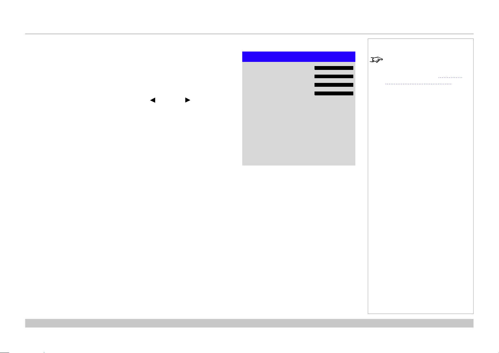
Digital Projection HIGHlite Laser II 3D Series
USING THE PROJECTOR
Geometry menu continued from previous page
Blanking
Use this feature to:
• t an odd-sized screen;
• cut off timecode dots in the top line of a picture;
• cut off subtitles, etc.
Select the edge you wish to blank and use the LEFT and RIGHT arrow buttons to
determine the amount of correction.
Use the Reset command to restore blanked edges.
Top
Bottom
Left
Right
Reset
Blanking
Notes
Some settings may be unavailable
0
0
0
0
depending on other settings. For
more information, see Possible
Combinations Of Settings further
in this guide.
Operating Guide
Rev B December 2016
page 51
Page 60
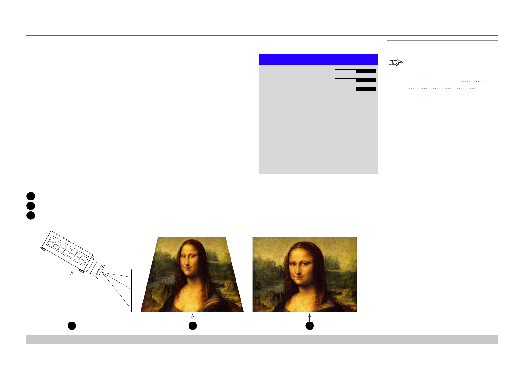
Digital Projection HIGHlite Laser II 3D Series
USING THE PROJECTOR
Geometry menu continued from previous page
Keystone
Use this setting to compensate for any distortion caused by the projector being in a
different horizontal or vertical plane to the screen.
Keystone example
1
The projector is positioned at an angle
2
The resulting image is distorted
3
The image is corrected when Keystone is applied
H Keystone
V Keystone
Rotation
Reset
Keystone
Notes
Some settings may be unavailable
0
0
0
depending on other settings. For
more information, see Possible
Combinations Of Settings further
in this guide.
Operating Guide
1 2 3
Rev B December 2016
page 52
Page 61

Digital Projection HIGHlite Laser II 3D Series
USING THE PROJECTOR
Geometry menu continued from previous page
Keystone settings
1
Projector to the left
The projector is positioned
to the left of the screen.
To correct, apply a positive
Horizontal Keystone
value using the RIGHT
arrow button.
2
Projector to the right
The projector is positioned
to the right of the screen.
To correct, apply a negative
Horizontal Keystone
value using the LEFT arrow
button.
3
Projector high
The projector is positioned
above the screen at a
downward angle.
To correct, apply a negative
Vertical Keystone value
using the DOWN arrow
button.
Notes
1
2
Some settings may be unavailable
depending on other settings. For
more information, see Possible
Combinations Of Settings further
in this guide.
4
Projector low
The projector is positioned
below the screen at an
upward angle.
To correct, apply a positive
Vertical Keystone value
using the UP arrow button.
5
Projector straight
The projector is directly
opposite the screen at a
right angle both horizontally
and vertically.
No correction is needed.
Operating Guide
4
53
Horizontal and vertical keystone corrections
Rev B December 2016
page 53
Page 62

Digital Projection HIGHlite Laser II 3D Series
USING THE PROJECTOR
Geometry menu continued from previous page
4 Corners
For each corner, apply horizontal and / or vertical correction as necessary to restore the
rectangular shape of the image.
Top Right Corner example
In this illustration, the top right corner requires both horizontal and vertical correction.
4 Corners
Top Left Corner
Top Right Corner
Bottom Left Corner
Bottom Right Corner
Reset
Top Right Corner Adjustment
Top Right Corner x
Top Right Corner y
t
p
Notes
u
u
u
u
0
u
0
q
Corner corrections provide a simple
setup for awkward installations and
irregular shaped screens that may
distort the image. To apply a similar
(but less exible) correction, while
preserving the original aspect ratio
of the image, use the Keystone
menu.
Some settings may be unavailable
depending on other settings. For
more information, see Possible
Combinations Of Settings further
in this guide.
Operating Guide
Top Right Corner correction
Rev B December 2016
page 54
Page 63

Digital Projection HIGHlite Laser II 3D Series
USING THE PROJECTOR
Geometry menu continued from previous page
Rotation
Use this feature for example to correct a mounting error causing the image not to be level
with the screen.
Rotation example
1
DMD™ area
The DMD™ is not rotated. It still covers the area that would be occupied by the
image without correction.
2
Rotated image
The image is smaller than the surrounding DMD™ area. It is scaled in order to
remain within the DMD™ area.
3
Angle of rotation
The angle equals a quarter of the Rotation setting.
In this example the angle is 5°, therefore Rotation = 20.
1
Rotation
Reset
Rotation
Notes
0
Some settings may be unavailable
depending on other settings. For
more information, see Possible
Combinations Of Settings further
in this guide.
2
Operating Guide
3
Rev B December 2016
page 55
Page 64

Digital Projection HIGHlite Laser II 3D Series
USING THE PROJECTOR
Geometry menu continued from previous page
Pincushion / Barrel
Pincushion or barrel distortions are the result of poor or incorrect tensioning of the screen
or using a surface that is not at.
Use the Pincushion / Barrel control to compensate electronically for such distortions.
You can also use this menu to make simple panoramic screen corrections without using
external processors.
Pincushion / Barrel example
The illustration shows pincushion and barrel correction applied both horizontally and vertically, in equal measures.
H Pin/Barrel
V Pin/Barrel
Keystone
Reset
Pincushion / Barrel
Notes
Some settings may be unavailable
0
0
u
depending on other settings. For
more information, see Possible
Combinations Of Settings further
in this guide.
Operating Guide
Pincushion Barrel
Rev B December 2016
page 56
Page 65

Digital Projection HIGHlite Laser II 3D Series
USING THE PROJECTOR
Edge Blend menu
Use this menu to blend together images from an array of two or more projectors.
The feature feathers the light output of the projector within the edges that overlap with
other projectors in the array: as a result, the overlapping edges are evenly lit and easily
blend in with the rest of the image.
• Edge Blend
Enable and disable Edge Blend
• Align Pattern
Add markers to the image showing the edges of the blend area and making the
overlaps more visible to help adjust the physical position of the projectors in the array.
• Blend Width
Determine the width of the blended regions.
• Black Level Uplift
Adjust black levels to compensate if the blended regions appear brighter than the rest
of the image.
• Reset
Reset all Edge Blend settings to their factory default values.
Edge Blend
Align Pattern
Blend Width
Black Level Uplift
Reset
Edge Blend
On
Off
Notes
When Edge Blend is set to Off,
u
u
all other edge blend settings are
disabled.
The picture in the blend region
needs to be delivered to all
overlapping projectors, which
may require a special setup of the
source.
Some settings may be unavailable
depending on other settings. For
more information, see Possible
Combinations Of Settings further
in this guide.
Operating Guide
Rev B December 2016
page 57
Page 66

Digital Projection HIGHlite Laser II 3D Series
USING THE PROJECTOR
Edge Blend menu continued from previous page
Blend Width
Use the LEFT and RIGHT arrow buttons to set the width of the blended regions:
1
Top
2
Bottom
3
Left
4
Right
3
1 2
4
Top
Bottom
Left
Right
Blend Width
0
0
0
0
Notes
Some settings may be unavailable
depending on other settings. For
more information, see Possible
Combinations Of Settings further
in this guide.
Operating Guide
Rev B December 2016
page 58
Page 67
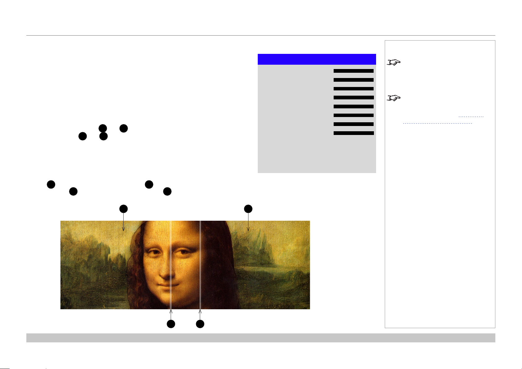
Digital Projection HIGHlite Laser II 3D Series
USING THE PROJECTOR
Edge Blend menu continued from previous page
Black Level Uplift
Black in the blended regions appears less dark than in the rest of the image. To
compensate fo this, use this menu to raise the black levels of the rest of the image:
• Set All to the required amount of black level correction. This will apply equal
correction to the black levels of all colors.
• If necessary, use the individual color sliders (Red, Green and Blue) for ne
adjustment.
You may experience artifacts at the edges where the blended region of one projector
overlaps the pond of mirrors of its neighbor. In the example below, the blended image
comes from two projectors, 1 and 2. Both images have black level uplift applied;
as a result, artifacts 3 and 4 have emerged at the edges where the black level uplift
region of one projector overlaps the pond of mirrors of the other.
To remove the artifacts, you need to slightly reduce the size of the black level uplift region
of each projector so it does not overlap the pond of mirrors of the other projector.
• Depending on your array, use Top, Bottom, Left and/or Right to reduce the black
level uplift size. In the example below, use the Right slider of the projector on the
left 1 to remove the artifact on the right 4, and the Left slider of the projector
on the right 2 to remove the artifact on the left 3.
1 2
Top
Bottom
Left
Right
All
Red
Green
Blue
Black Level Uplift
0
0
0
0
0
0
0
0
Notes
Enable Align Pattern from the
Edge Blend menu to see the black
level uplift area.
Some settings may be unavailable
depending on other settings. For
more information, see Possible
Combinations Of Settings further
in this guide.
Operating Guide
3 4
Rev B December 2016
page 59
Page 68

Digital Projection HIGHlite Laser II 3D Series
USING THE PROJECTOR
3D menu
Use this menu to enable, disable and set up 3D input, as follows:
• 3D Format — Off, Auto, Side by Side (Half), Top and Bottom, Dual Pipe and
Frame Sequential.
• Eye Swap — Normal and Reverse (set to Rever se if the left- and right-eye images
are displayed in the wrong order)
• Dark Time — 0.65 ms, 1.3 ms and 1.95 ms. Set to reduce the effect of images
overlapping while the glasses are switching.
3D Sync
• Offset — use the LEFT and RIGHT arrow buttons to compensate for signal
processing delays in the projector.
• Reference— External, Internal and Auto.
3D Format
Eye Swap
Dark Time
3D Sync
Offset
Reference
3D
100
Auto
Normal
1.95 ms
Internal
Notes
For further information about
supported 3D formats, see 3D
connections in the Connection
Guide.
If 3D Format is set to Off, all other
3D settings will be unavailable.
Some settings may be unavailable
depending on other settings. For
more information, see Possible
Combinations Of Settings further
in this guide.
Frame Sequential is supported on
the HDMI, DVI-D and DisplayPort
inputs only.
3D video is only possible on the
HDMI, HDBaseT, DisplayPort and
DVI inputs.
The Frame Packing format is
automatically detected by the
projector.
Operating Guide
See also 3D types and Some 3D
settings explained further in this
guide.
Rev B December 2016
page 60
Page 69

Digital Projection HIGHlite Laser II 3D Series
USING THE PROJECTOR
3D menu continued from previous page
3D types
In most situations you can use the Auto setting to have the projector automatically detect the
format. Otherwise, consider the notes below to help you set up the 3D input manually.
The following 3D formats are supported:
• Dual Pipe (LEFT and RIGHT)
The left and right eye images are delivered on two separate HDMI links, which the projector
will interleave for 3D display.
• Frame Packing
This format will be detected, re-synchronised, frame-multiplied and displayed at 96 Hz with
the left eye / right eye dominance automatically extracted from the video data. You need to
optimize Dark Time and Sync Delay manually to suit your chosen switching glasses.
• Top and Bottom
Sets the projector to reformat the video frames and map them to the display with the left
eye / right eye dominance automatically extracted from the video data. You need to optimize
Dark Time and Sync Delay manually to suit your chosen switching glasses.
Notes
L
HDMI 1
R
HDMI 2
Dual Pipe
L
R
Frame Packing
L
• Side by Side (Half): interlaced and progressive, 50 and 60Hz
The side-by-side image will be de-interlaced (if appropriate), resized and then sequentially
displayed at 100 or 120 Hz. The left eye / right eye dominance will be automatically extracted
from the video data, however you will need to optimize Dark Time and Sync Delay manually
to suit your chosen switching glasses.
Dark Time and Sync Delay need to be set only once, to optimize the image for the glasses in
use.
Operating Guide
R
Top-and-Bottom
L R
Side-by-Side (Half)
Rev B December 2016
page 61
Page 70

Digital Projection HIGHlite Laser II 3D Series
USING THE PROJECTOR
3D menu continued from previous page
Some 3D settings explained
Dark Time
Ghosting can be caused by the left and right images
overlapping during the time that the ZScreen or 3D
glasses are switching. Dark Time allows you to
minimize this effect.
Eye Swap
The outgoing 3D frames are in pairs - the dominant
frame being presented rst. You can determine which
frame should be the dominant one.
By convention the default setting is Left.
Sync Delay
The sync signal from the 3D server will be in phase with
the frames generated by its graphics card. However,
to compensate for processing delays in the projector,
Sync Delay introduces a delay to the sync output
signal sent to the ZScreen or 3D glasses.
Fully on
Fully off
sync signal
Incoming
video
Incoming
Left
Dark
time
Dominance Left
LEFT 1 RIGHT 1 LEFT 2 RIGHT 2 LEFT 3 RIGHT 3
Dominance Right
Dark
time
Right
Dark
time
LEFT 3RIGHT 1 LEFT 1 RIGHT 2 LEFT 2 RIGHT 3
Notes
In order to achieve maximum light
output and a smooth grayscale,
whilst eliminating ghosting,
the following procedure is
recommended:
1. Set Dark Time to a value
appropriate to the glasses or
ZScreen, say 1.3 ms or 1.95 ms.
2. Adjust Sync Offset time to eliminate
ghosting and achieve a smooth
grayscale.
3. Repeat steps 1 and 2 until the best
result is obtained.
Operating Guide
Video signal with
processing delays (and
dark time adjustment)
Sync output signal
after delay adjustment
Rev B December 2016
page 62
Page 71

Digital Projection HIGHlite Laser II 3D Series
USING THE PROJECTOR
3D menu continued from previous page
Frame rate multiplication in 3D images
When displaying a low frame rate 3D video, the projector
multiplies the frame rate to obtain a icker-free image. For
example, a 60Hz frame rate is doubled to 120 Hz, or a 48 Hz
frame rate is tripled to 144 Hz.
Frame rate multiplication is an automatic process. It occurs in
the background and cannot be modied by the user.
IN
OUT
L1
R1 L3
R1
L2 R2
L1L1R1 R2L2 L3R2
x2 example
L2
Notes
Operating Guide
Rev B December 2016
page 63
Page 72

Digital Projection HIGHlite Laser II 3D Series
USING THE PROJECTOR
Laser menu
• Power Mode
• Eco will automatically set the laser power to 80%.
• Normal will set the power to 100%.
• Set to Custom if you wish to adjust the power manually.
• Power Level
This setting is only available if Power Mode is set to Custom.
Choose a value between 20 and 100, ranging from 20% to 100% laser power.
Power Mode
Power Level
Laser
Notes
Normal
— — — —
Operating Guide
Rev B December 2016
page 64
Page 73

Digital Projection HIGHlite Laser II 3D Series
USING THE PROJECTOR
Setup menu
• Orientation
Choose from Front Tabletop, Front Ceiling, Rear Tabletop, Rear Ceiling and
Auto-front.
• Cooling Condition
Choose from Table, Ceiling, Freetilt and Auto.
• High Altitude
Choose from On and Auto.
• Screen Setting
Choose from 16:10, 16:9 and 4:3.
• ColorMax
Set up user-dened color gamut values.
• Power On/Off
Access the submenu to set up automatic projector power on and power off.
• Clock Adjust
Access the submenu to set current date and local time.
• Startup Logo
Set this to On if you want the DP logo to show when the projector is rst switched on.
• Blank Screen
Choose from Logo, Black, Blue and White.
• Trigger1 and Trigger 2
Choose from Screen, 5:4, 4:3, 16:10, 16:9, 1.88, 2.35, TheaterScope, Source,
Unscaled or RS232 to determine what will cause each trigger output to activate.
Highlight the DOWN arrow at the bottom of the page and press ENTER/OK to navigate
to the second Setup menu page.
Orientation
Cooling Condition
High Altitude
Screen Setting
ColorMax
Power On/Off
Clock Adjust
Startup Logo
Blank Screen
Trigger-1
Trigger-2
Setup
q
Auto-front
Auto
Auto
16:10
On
Logo
Off
Off
Notes
Auto-front automatically detects
the projector’s position and sets the
orientation accordingly.
u
u
u
Use Screen Setting in combination
with the Aspect Ratio feature found
in the Geometry menu to provide
the best t for the projected image
and to minimize letterboxing and
pillarboxing.
The Trigger 1 and Trigger 2
functions output 12 V depending on
the set value:
• If Screen is set, the trigger will
be activated when the projector
is switched on.
• If RS232 is set, the trigger will
be activated upon receiving a
protocol command.
• If any of the other values
are set, the trigger
will be activated if the
Geometry > Aspect Ratio
function is set to match the
trigger value. For example, if
Trigger 1 is set to 4:3, it will
output a 12 V charge if you set
Geometry > Aspect Ratio to
4:3.
Operating Guide
Rev B December 2016
page 65
Page 74

Digital Projection HIGHlite Laser II 3D Series
USING THE PROJECTOR
Setup menu continued from previous page
• Auto Source
If this setting is On, the projector will automatically search for an active input source.
• Infrared Remote
Set to Off if you wish to disable the remote control.
• IR Code
The projector and the remote control need a matching IR code: a two-digit number
between 00 and 99.
The default IR code is 00. This is also a master code, which, if assigned to a remote,
will work regardless of the value assigned to the projector.
To assign an IR code for the projector:
1. Select IR Code.
2. Use the UP and DOWN arrow buttons to change the values.
To assign an IR code for the remote:
1. Press and hold the ADDR button on the remote until the indicator starts ashing.
2. Release the ADDR button and while the indicator is still ashing, enter a two-
digit address using the numeric input buttons. The indicator will ash three times
quickly to conrm the change.
• IR Code Reset
Use this command to unassign an IR code from the projector. This will revert the
IR Code value to 00.
To unassign an IR code from the remote control,
• Press and hold ALT and ADDR simultaneously until the indicator ashes to
conrm the change.
• OSD Settings
Access this submenu to adjust the appearance and position of the on-screen display.
• Memory
Access this submenu to save up to four presets containing custom combinations of
image settings, or to recall a saved preset.
Setup
p
Auto Source Off
Infrared Remote
IR Code
IR Code Reset
OSD Settings
Memory
On
0
Notes
If you turn the remote control off,
you can only turn it back on again
from the control panel or via the
Projector Controller application.
The Projector Controller software
is available for download from the
u
u
Digital Projection website, free of
charge.
A wired remote control will also be
disabled if Infrared Remote is set
to Off.
Highlight the UP arrow at the top of the page and press ENTER/OK to go back to the
rst Setup menu page.
Operating Guide
Rev B December 2016
page 66
Page 75

Digital Projection HIGHlite Laser II 3D Series
USING THE PROJECTOR
Color menu continued from previous page
ColorMax Setting
ColorMax Setting permits seven point
color matching of red, green, blue,
yellow, cyan, magenta and white.
You can enter your own gamut values
here, or edit values you have imported
using the Projector Controller
software.
Dening your own colorspace with
individual x and y coordinates for each
color enables you to match not only the
whites but each individual color as well.
Highlight the submenu you wish to
open and press ENTER/OK to conrm
your choice.
Measured Data / Target Data
1. Use the UP and DOWN arrow
buttons to highlight a color, then
use the LEFT and RIGHT
arrow buttons to navigate to the x
or y coordinate.
2. Use the UP and DOWN arrow
buttons to increase and decrease
the value, respectively.
3. Exit edit mode:
• press ENTER/OK, if you want
to save the edited values.
• press EXIT, if you do not wish
to save the edited values
4. If necessary, highlight another color
and repeat the procedure.
Measured Data
Red
Green
Blue
White x: 0.276 y: 0.283
x: 0.658 y: 0.339
x: 0.315 y: 0.662
x: 0.146 y: 0.043
ColorMax Setting
Measured Data
Target Data – User 1
Target Data – User 2
Reset
Target Data – User 1
Red
Green
Blue
Yellow x: 0.419 y: 0.505
Cyan
Magenta
White x: 0.285 y: 0.302
x: 0.640 y: 0.390
x: 0.300 y: 0.600
x: 0.150 y: 0.060
x: 0.225 y: 0.329
x: 0.321 y: 0.154
Notes
u
u
u
The Projector Controller software
is available for download from the
Digital Projection website, free of
charge.
This tool is best used in conjunction
with a specialized light meter (a
photo spectrometer) to measure
color parameters within a particular
installation. However, the preloaded
generic factory default data set
is designed to give more than
satisfactory results.
Operating Guide
Rev B December 2016
page 67
Page 76

Digital Projection HIGHlite Laser II 3D Series
USING THE PROJECTOR
Setup menu continued from previous page
Power On/Off
• Auto Power Off
Set this to On if you want the projector to go into STANDBY mode when no input
source is detected for 20 minutes.
• Auto Power On
Set this to On if you want the projector to start up immediately when the mains is
connected.
Set this to Off if you want the projector to go into STANDBY mode when the mains
is connected. In this case, the projector will not start up until the POWER button is
pressed on the control panel or the ON button is pressed on the remote control.
• Scheduled on/off
Access this submenu to create a weekly schedule for automatic on and off times:
1. Set a schedule:
• Use he UP and DOWN arrow buttons to highlight a row, then press
ENTER/OK to enable edit mode.
• Within a row, navigate with the LEFT and RIGHT arrow buttons. Set
values with he UP and DOWN arrow buttons.
• To exit edit mode, press ENTER/OK. Alternatively, press EXIT if you don’t
want the changes to take effect. Move to another row using he UP and
DOWN arrow buttons.
2. To enable the schedule, set Schedule to On.
Power On/Off
Auto Power Off
Auto Power On
Scheduled on/off
Off
Off
Scheduled on/off
Schedule Off
S M T W T F S Time
On T ¨ ¨ ¨ ¨ ¨ ¨ 12: 34
Off
T ¨ ¨ ¨ ¨ ¨ ¨ 12: 34
T ¨ ¨ ¨ ¨ ¨ ¨ 12: 34
On
Off
T ¨ ¨ ¨ ¨ ¨ ¨ 12: 34
Notes
u
Operating Guide
Rev B December 2016
page 68
Page 77

Digital Projection HIGHlite Laser II 3D Series
USING THE PROJECTOR
Setup menu continued from previous page
Clock Adjust
Use this menu to set date (in dd:MM:yyyy format), time (in HH:mm format) and time
zone.
The date and time set here will affect any schedule created within the Power On/Off
menu.
Clock Adjust
Date (dd:MM:yyyy)
Time (HH:mm)
Time Zone
20:11:2015
14:00
UTC 0
Notes
Notes
Operating Guide
Rev B December 2016
page 69
Page 78

Digital Projection HIGHlite Laser II 3D Series
USING THE PROJECTOR
Setup menu continued from previous page
OSD Settings
• Language sets the OSD language.
• Menu Position determines where the OSD should appear ont he screen when
activated.
• Menu Transparency sets OSD transparency between 0% (no transparency), 25%,
50% and 75%.
• Time Out determines how long the OSD should remain on screen if no buttons are
pressed. Choose Always On to disable this feature.
• Message Box determines whether projector status messages should appear on the
screen.
Memory
The current image settings can be saved as a preset, which you can recall later. The
default settings can be recalled at any time as well.
Up to four custom presets can be stored for each input.
The following settings are saved in a preset:
• From the Image menu — Gamma, Brightness, Contrast, Saturation, Hue,
Sharpness and Noise Reduction
• From the Color menu — Color Space, Color Mode, ColorMax,
Color Temperature, Dynamic Black, RGB Lift and RGB Gain
• From the Geometry menu — Aspect Ratio and Overscan
OSD Settings
Language
Menu Position
Menu Transparency
Time Out
Message Box
Memory
Recall Memory
Save Settings
Notes
English
Center
0
30 Seconds
On
Presets from one input cannot be
applied to another input.
Default
Preset A
To recall a saved preset:
• Select Recall Memory and press ENTER/OK, then select a preset from Preset A to
Preset D. Select Default to load factory default values.
To save a preset:
• Select Save Settings and press ENTER/OK, then choose from Preset A, Preset B,
Preset C and Preset D.
Operating Guide
Rev B December 2016
page 70
Page 79

Digital Projection HIGHlite Laser II 3D Series
USING THE PROJECTOR
Network menu
• Network Mode
Choose between Projector Control and Service.
• Standby Power
If this setting is On, the LAN socket remains active when the projector is in STANDBY
mode. If the setting is Off, the LAN socket is disabled when the projector is in
STANDBY mode.
• DHCP, IP, Subnet Mask, Gateway, DNS
Set DHCP to On if the IP address is to be assigned by a DHCP server, or Off if it is to
be set here.
If DHCP is On, it will not be possible to edit IP Address, Subnet Mask, Gateway or
DNS.
If DHCP is set to Off, edit IP Address, Subnet Mask, Gateway and DNS as
required.
• MAC
This eld is read-only.
• AMX
Switch on or off.
Network Mode
Standby Power
DHCP
IP
Subnet Mask
Gateway
DNS
MAC
AMX
Network
Projector Control
Off
Off
192 . 168 . 000 . 100
255 . 255 . 255 . 000
000 . 000 . 000 . 000
000 . 000 . 000 . 000
00: 18: 27: 2d: f2: 06
Off
Notes
Operating Guide
Rev B December 2016
page 71
Page 80

Digital Projection HIGHlite Laser II 3D Series
USING THE PROJECTOR
PIP menu
• PIP
Turn PIP on and off.
• Source
Select an input source for the PIP image.
Any combinations are possible between main and PIP input source, as long as the
two inputs are not from the same group:
Group 1 Group 2
HDMI 1 HDMI 2
DVI VGA
DisplayPort COMP
HDBaseT 3G-SDI
• Position
Set the location of the PIP image on the screen. Choose from Top-Left, Top-Right,
Bottom-Left, Bottom-Right and PBP.
PIP
Source
Position
PIP
Off
HDMI1
Top-Left
Notes
Some settings may be unavailable
depending on other settings. For
more information, see Possible
Combinations Of Settings further
in this guide.
Operating Guide
Rev B December 2016
page 72
Page 81

Digital Projection HIGHlite Laser II 3D Series
USING THE PROJECTOR
Information menu
This menu gives information about software and hardware conguration, input source and
laser operating times It also allows you to restore the factory default settings.
Signal Format
Information
Model Name
Serial Number
Software Version 1
Software Version 2
Active / PIP Source
Signal Format
Laser Hours
System Status
Thermal Status
Factory Reset
Signal Format
Active Source
Timing
H Refresh
V Refresh
Pixel Clock
Notes
E-Vision Laser 8500
X000XXXXX0000
MD03-SE10-FE09
LE07-14-RE04-3092
HDMI2 / DVI
u
00041 HRS
u
u
1080p/60Hz
67.500 KHz
60.00 Hz
148.500 MHz
Operating Guide
PIP Source
Timing
H Refresh
V Refresh
Pixel Clock
576p/50Hz
31.250 KHz
50.00 Hz
27.0 MHz
Rev B December 2016
page 73
Page 82

Digital Projection HIGHlite Laser II 3D Series
USING THE PROJECTOR
Information menu continued from previous page
System Status
Thermal Status
System Status
Atmospheric Pressure
AC Voltage
Ceiling Mode
Tilt Angle
Portrait Angle
Altitude Mode
Laser Power
Thermal Status
Inlet 1/2 Temp.
DMD Temp.
Laser 1/2 Temp.
Outside Temp.
Fan 1-3 Speed
Fan 4-6 Speed
Fan 7-9 Speed
Fan 10-12 Speed
Fan 13-15 Speed
Fan 16 Speed
Water Pump Speed
Notes
98988 Pa (116 m)
160V – 264V
0
4 deg
0 deg
Low
100%
24 / 34 (C)
38 (C)
49 / 42 (C)
32 (C)
1399 / 1402 / 1391
1410 / 1200 / 1205
1211 / 1407 / 1410
0 / 3005 / 3007
2986 / 2984 / 2984
3020 / NA / NA
3506
Operating Guide
Rev B December 2016
page 74
Page 83

Digital Projection HIGHlite Laser II 3D Series
USING THE PROJECTOR
Information menu continued from previous page
Factory Reset
To restore the factory default settings:
1. Navigate to Factory Reset and press ENTER/OK.
2. When prompted, press ENTER/OK to conrm your choice, or press EXIT to cancel.
Information
Model Name
Serial Number
Software Version 1
Software Version 2
Active Source
WARNING
All user settings will be lost!
Signal Format
Laser Hours
Press OK to confirm
Press Exit to cancel
System Status
Thermal Status
Factory Reset
Factory Reset
E-Vision Laser 8500
X000XXXXX0000
MD03-SE10-FE09
LE07-14-RE04-3092
HDMI
00041 HRS
Notes
u
u
u
OK
Operating Guide
Rev B December 2016
page 75
Page 84

Digital Projection HIGHlite Laser II 3D Series
POSSIBLE COMBINATIONS OF SETTINGS
Possible Combinations Of Settings
Some OSD settings cannot be used in combination with others. The table below shows the possible combinations.
A tick (ü) means that the combination is possible. A cross () means applying the new setting is impossible if the existing setting is being
used. A number sign (#) means applying the new setting will disable the existing one.
New
Setting
Existing
Setting
3D
Warp /
Geometry
Blending
Picture Mode
Color Temp.
Overscan
Aspect Ratio
3D
Warp /
Color
Mode
Geometry
Blending
Picture
Temp.
Overscan
Ratio
Aspect
Zoom
Digital
ü ü ü
ü ü ü ü ü ü ü ü ü
ü ü ü ü ü ü ü ü
#
#
#
ü ü ü ü ü ü ü ü
ü ü ü ü ü ü ü ü
ü ü ü ü ü ü ü ü
ü ü ü ü ü ü ü ü ü
PIP
Black
Dynamic
Notes
Digital Zoom
PIP
Dynamic
Black
Operating Guide
#
#
#
ü ü ü ü ü ü ü ü
ü ü ü ü ü ü ü ü
ü
#
ü ü ü ü ü ü
Rev B December 2016
page 76
Page 85

HIGHlite Laser II 3D Series
High Brightness Digital Video Projector
4
REFERENCE GUIDE
Rev B December 2016
Page 86

Digital Projection HIGHlite Laser II 3D Series
IN THIS GUIDE
IN THIS GUIDE
The DMD™ ........................................................................................................... 80
Choosing A Lens ................................................................................................ 82
Basic calculation .......................................................................................................83
Basic calculation example .......................................................................................84
Full lens calculation ..................................................................................................85
Introducing TRC ..............................................................................................................85
Calculating TRC ..............................................................................................................86
Calculating the throw ratio with TRC ...............................................................................87
Full lens calculation example ..................................................................................88
Screen Requirements ...................................................................................... 89
Fitting the image to the DMD™ ................................................................................89
WUXGA images displayed full width ...............................................................................89
WUXGA images displayed with a height of 1080 pixels .................................................90
WUXGA images displayed full height .............................................................................91
Diagonal screen sizes ...............................................................................................92
Fitting the image to the screen ................................................................................93
Positioning the screen and projector ......................................................................94
Positioning The Image .................................................................................... 95
Maximum offset range ..............................................................................................97
Aspect Ratios Explained ................................................................................ 98
Aspect ratio examples ..............................................................................................99
Frame Rates And Pulldowns Explained ................................................... 101
Interlaced and progressive scan .......................................................................... 101
Frame rates of image sources .............................................................................. 101
Pulldowns - conversion into destination formats ............................................... 102
2:3 (normal) pulldown .................................................................................................. 102
2:3:3:2 (advanced) pulldown ........................................................................................ 103
Appendix A: Lens Part Numbers ................................................................ 104
Appendix B: Lens Charts .............................................................................. 105
How to use the lens charts ........................................................................................... 105
TRC values applied in the charts ................................................................................. 106
Fixed lenses - full DMD™ width images ...................................................................... 107
Zoom lenses - full DMD™ width images ...................................................................... 108
Fixed lenses - 1.25:1 images ....................................................................................... 109
Zoom lenses - 1.25:1 images ....................................................................................... 110
Fixed lenses - 1.33:1 images ........................................................................................111
Zoom lenses - 1.33:1 images ....................................................................................... 112
Appendix C: Supported Signal Input Modes .......................................... 113
2D formats ...............................................................................................................113
3D formats ...............................................................................................................115
Appendix D: Menu Map .................................................................................. 117
INPUT .......................................................................................................................117
TEST PATTERN ........................................................................................................117
LENS .........................................................................................................................117
IMAGE ......................................................................................................................118
COLOR .....................................................................................................................119
GEOMETRY ............................................................................................................. 121
EDGE BLEND .......................................................................................................... 123
3D ............................................................................................................................. 123
LASER ..................................................................................................................... 123
SETUP ..................................................................................................................... 124
NETWORK ............................................................................................................... 126
PIP ........................................................................................................................... 126
INFORMATION ........................................................................................................ 127
Reference Guide
Rev B December 2016
Page 87

Digital Projection HIGHlite Laser II 3D Series
IN THIS GUIDE
IN THIS GUIDE (continued)
Appendix E: Wiring Details .......................................................................... 128
Signal inputs and outputs ..................................................................................... 128
VGA ..............................................................................................................................128
HDMI 1 and 2 ............................................................................................................... 129
DisplayPort ................................................................................................................... 130
3G-SDI In, 3G-SDI Out ................................................................................................ 131
COMPONENT .............................................................................................................. 131
Control connections .............................................................................................. 132
LAN .............................................................................................................................. 132
RS232 .......................................................................................................................... 132
Trigger 1 & Trigger 2 .................................................................................................... 133
IR input ......................................................................................................................... 133
3D Sync IN and 3D Sync OUT ..................................................................................... 133
Appendix F: Glossary Of Terms ................................................................. 134
Technical Specications .............................................................................. 145
Models ..................................................................................................................... 145
Inputs and outputs ................................................................................................. 146
Bandwidth ............................................................................................................... 146
Remote control and keypad .................................................................................. 146
Automation control ................................................................................................ 146
Color temperature .................................................................................................. 146
Lenses ..................................................................................................................... 147
Lens mount ............................................................................................................. 147
Mechanical mounting ............................................................................................ 147
Orientation .............................................................................................................. 147
Electricalandphysicalspecications ................................................................. 148
Safety & EMC regulations ..................................................................................... 148
Reference Guide
Rev B December 2016
Page 88

Digital Projection HIGHlite Laser II 3D Series
THE DMD™
The DMD™
A DMD™ (Digital Micromirror Device™) is a true digital light modulator which utilises an array of up to 2.3 million moving aluminium mirrors,
with each one representing a pixel in the nal projected image. The outermost micromirrors in the array remain inactive (pond of mirrors)
and are not used in constructing the image.
1
Casing
2
Light shield
3
Pond of mirrors
4
Array
Each mirror element is suspended over address electrodes by a torsion hinge between two posts.
1
Support posts
2
Mirror element
3
Torsion hinges
1
2
3
4
DMD™
1
2
Notes
4
Offset address electrode
Reference Guide
3
4
Mirror element with tilt mechanism
Rev B December 2016
page 80
Page 89

Digital Projection HIGHlite Laser II 3D Series
THE DMD™
Depending on the voltage polarity applied, each mirror will either tilt to the left to produce a bright pixel or to the right for a dark pixel. When
light is applied to the complete DMD™, only the light redirected from a mirror tilting to the left is projected.
Notes
1
Projection lens
2
Incoming light from the illumination module
3
Mirror element tilted to the right
4
Mirror element tilted to the left
5
Reectedlight,lefttilt
6
Light dump
7
Reectedlight,righttilt
1
2
3
4
5
6
7
Light ow
The projector optically lters white light from the illumination module into its constituent red, green and blue. Each color illuminates a separate
DMD™ whose modulated output is then recombined with the other two to form the projected full color image.
1
Illumination module
2
Opticallteringoflightintored,greenandblue
3
Projection lens
1 2 3
white light RGB light
4
DMD™ devices
5
Full color image displayed on screen
Reference Guide
blue
light
green
light
4 5
red
light
Filtering process
Rev B December 2016
page 81
Page 90

Digital Projection HIGHlite Laser II 3D Series
CHOOSING A LENS
Choosing A Lens
A number of lenses are available. Which lens you choose depends on the screen size, image aspect ratio, throw distance and light output.
The following table shows all available lenses in order of their throw ratios:
Throw ratios Throw distance range
0.77 : 1 xed lens 1.3 - 15 m (4.3 - 49.2 ft)
1.16 : 1 xed lens 1.4 - 25 m (4.6 - 82 ft)
1.45 - 1.74 : 1 zoom lens 1.8 - 9.3 m (5.9 - 30.5 ft)
1.74 - 2.17 : 1 zoom lens 2.2 - 11.8 m (7.2 - 38.7 ft)
2.17 - 2.90 : 1 zoom lens 2.7 - 15.4 m (8.9 - 50.5 ft)
2.90 - 4.34 : 1 zoom lens 3.6 - 22.5 m (11.8 - 73.8 ft)
4.34 - 6.76 : 1 zoom lens 5.5 - 35 m (18 - 114.8 ft)
To choose a lens, either calculate the throw ratio required, or use the lens charts provided in Appendix B at the end of this document.
Notes
For information about individual lens
part numbers, see Appendix A at
the end of this document.
See also Appendix B: Lens Charts
at the end of this document.
Do not use the short lens hood
with the 4.34 - 6.76 : 1 zoom lens.
For further information about using
the right lens and hood, see The
lens hood in the Installation and
Quick-Start Guide.
Reference Guide
Rev B December 2016
page 82
Page 91

Digital Projection HIGHlite Laser II 3D Series
CHOOSING A LENS
Basic calculation
Identify the required lens by calculating the throw ratio.
A throw ratio is the ratio of the throw distance to the screen width:
Throw distance
Throw ratio =
Screen width
1. Use the formula above to obtain the required throw ratio.
2. Match the throw ratio with a lens from the table below:
Throw ratios Throw distance range
0.77 : 1 xed lens 1.3 - 15 m (4.3 - 49.2 ft)
1.16 : 1 xed lens 1.4 - 25 m (4.6 - 82 ft)
1.45 - 1.74 : 1 zoom lens 1.8 - 9.3 m (5.9 - 30.5 ft)
1.74 - 2.17 : 1 zoom lens 2.2 - 11.8 m (7.2 - 38.7 ft)
2.17 - 2.90 : 1 zoom lens 2.7 - 15.4 m (8.9 - 50.5 ft)
2.90 - 4.34 : 1 zoom lens 3.6 - 22.5 m (11.8 - 73.8 ft)
4.34 - 6.76 : 1 zoom lens 5.5 - 35 m (18 - 114.8 ft)
3. Ensure the required throw distance is within the range covered
by the lens.
Notes
1
2
The basic calculation on this page
does not take into consideration
DMD™ and image size, which could
affect the throw ratio. For a more
complex and realistic calculation,
see Full lens calculation in this
section.
When calculating the throw ratio, be
sure to use identical measurement
units for both the throw distance and
the screen width.
1
Screen width
For information about individual lens
2
Throw distance
part numbers, see Appendix A at
the end of this document.
See also Appendix B: Lens Charts
at the end of this document.
Reference Guide
Do not use the short lens hood
with the 4.34 - 6.76 : 1 zoom lens.
For further information about using
the right lens and hood, see The
lens hood in the Installation and
Quick-Start Guide.
Rev B December 2016
page 83
Page 92

Digital Projection HIGHlite Laser II 3D Series
CHOOSING A LENS
Basic calculation example
1. Calculate the throw ratio using the formula.
Your screen is 4.5 m wide and you wish to place the projector
approximately 11 m from the screen. The throw ratio will then be
11
2. Match the result with the lens table.
The lens matching a throw ratio of 2.44 is the 2.17 - 2.90 : 1
zoom lens.
3. Check whether the lens covers the required throw distance.
The range quoted for the 2.17 - 2.90 : 1 zoom lens is 2.7 - 15.4
m. The required distance of 11 m is within the range.
= 2.44
4.5
INFORMATION YOU NEED FOR THIS CALCULATION
• The throw ratio formula:
Throw distance
Throw ratio =
Screen width
• The lens table:
Throw ratios Throw distance range
0.77 : 1 xed lens 1.3 - 15 m (4.3 - 49.2 ft)
1.16 : 1 xed lens 1.4 - 25 m (4.6 - 82 ft)
1.45 - 1.74 : 1 zoom lens 1.8 - 9.3 m (5.9 - 30.5 ft)
1.74 - 2.17 : 1 zoom lens 2.2 - 11.8 m (7.2 - 38.7 ft)
2.17 - 2.90 : 1 zoom lens 2.7 - 15.4 m (8.9 - 50.5 ft)
2.90 - 4.34 : 1 zoom lens 3.6 - 22.5 m (11.8 - 73.8 ft)
4.34 - 6.76 : 1 zoom lens 5.5 - 35 m (18 - 114.8 ft)
Notes
The basic calculation on this page
does not take into consideration
DMD™ and image size, which could
affect the throw ratio. For a more
complex and realistic calculation,
see Full lens calculation in this
section.
For information about individual lens
part numbers, see Appendix A at
the end of this document.
Reference Guide
Rev B December 2016
page 84
Page 93

Digital Projection HIGHlite Laser II 3D Series
CHOOSING A LENS
Full lens calculation
Introducing TRC
The choice of lens will affect the image size and will address discrepancies between the
DMD™ resolution and the source.
When an image lls the height of the DMD™ but not the width, it uses less than 100% of
the DMD™ surface. A lens chosen using the basic formula may produce an image that is
considerably smaller than the actual screen.
To compensate for loss of screen space in such situations, you need to increase the throw
ratio using a Throw Ratio Correction (TRC).
Example
Fig. 1 illustrates a 4:3 image within a WUXGA DMD™.
When a WUXGA projector is used for a 4:3 image, the image does not ll the width of the
DMD™, creating a pillarboxing effect - blank spaces to the left and right.
Fig. 2 shows the same image projected on a 4:3 screen using a standard lens (chosen with
the basic calculation).
The DMD™ accurately lls the width of the screen; however, the pillarboxing is now part of the
projected image and is transferred to the screen.
The DMD™ does not ll the height of the screen, which has caused letterboxing - further
blank spaces at the top and bottom of the screen.
The image is now surrounded by blank space, which can be removed if the throw ratio is
increased.
Notes
TRC can only be applied if greater
than 1. If TRC is 1 or less, disregard
it and calculate the throw ratio using
the basic formula.
Fig. 1
Fig. 2
Fig. 3 shows the image projected on the same screen with a lens chosen using TRC.
The increased throw ratio has allowed the 4:3 image to ll the 4:3 screen seamlessly.
Reference Guide
Fig. 3
Rev B December 2016
page 85
Page 94

Digital Projection HIGHlite Laser II 3D Series
CHOOSING A LENS
Calculating TRC
To calculate TRC, use the following formula:
1.6 (DMD™ aspect ratio)
TRC =
Source aspect ratio
TRC table
Alternatively, you can save time by referencing the following table, which shows the TRC value for some popular image formats:
2.35:1 (Scope), 1920 x 817 pixels TRC < 1, not used
1.85:1 (Flat), 1920 x 1037 pixels TRC < 1, not used
1.78:1 (16:9), 1920 x 1080 TRC < 1, not used
1.66:1 (Vista), 1792 x 1080 pixels TRC < 1, not used
1.6:1 (16:10), 1728 x 1080 pixels TRC = 1, not used (native resolution)
1.33:1 (4:3), 1440 x 1080 pixels TRC = 1.2
1.25:1 (5:4), 1350 x 1080 pixels TRC = 1.28
Notes
TRC can only be applied if greater
than 1. If TRC is 1 or less, disregard
it and calculate the throw ratio using
the basic formula.
Reference Guide
Rev B December 2016
page 86
Page 95

Digital Projection HIGHlite Laser II 3D Series
CHOOSING A LENS
Calculating the throw ratio with TRC
1. For TRC > 1, amend the basic throw ratio formula as follows:
Throw distance
Throw ratio =
Screen width x TRC
2. Once a throw ratio is established, identify the matching lens from the table:
Throw ratios Throw distance range
0.77 : 1 xed lens 1.3 - 15 m (4.3 - 49.2 ft)
1.16 : 1 xed lens 1.4 - 25 m (4.6 - 82 ft)
1.45 - 1.74 : 1 zoom lens 1.8 - 9.3 m (5.9 - 30.5 ft)
1.74 - 2.17 : 1 zoom lens 2.2 - 11.8 m (7.2 - 38.7 ft)
2.17 - 2.90 : 1 zoom lens 2.7 - 15.4 m (8.9 - 50.5 ft)
2.90 - 4.34 : 1 zoom lens 3.6 - 22.5 m (11.8 - 73.8 ft)
4.34 - 6.76 : 1 zoom lens 5.5 - 35 m (18 - 114.8 ft)
3. Ensure the required throw distance is within the range of the matching lens.
Notes
TRC can only be applied if greater
than 1. If TRC is 1 or less, disregard
it and calculate the throw ratio using
the basic formula.
Do not use the short lens hood
with the 4.34 - 6.76 : 1 zoom lens.
For further information about using
the right lens and hood, see The
lens hood in the Installation and
Quick-Start Guide.
Reference Guide
Rev B December 2016
page 87
Page 96

Digital Projection HIGHlite Laser II 3D Series
CHOOSING A LENS
Full lens calculation example
Your screen is 4.5 m wide; you wish to place the projector
approximately 11 m from the screen. The source is 4:3.
1. Calculate TRC as follows:
1.6
TRC =
2. Calculate the throw ratio:
Throw ratio =
3. Find a match in the lens table.
The table shows that the matching lens is the 1.74 - 2.17 : 1
zoom lens.
4. Check whether the lens covers the required throw distance.
The range quoted for the 1.74 - 2.17 : 1 zoom lens is
2.2 - 11.8 m. The required distance of 11 m is within the
range.
= 1.2
1.33
11
= 2.04
4.5 x 1.2
INFORMATION YOU NEED FOR THESE CALCULATIONS
• The TRC formula
TRC =
DMD™ aspect ratio
Source aspect ratio
• The TRC table (to use instead of the formula)
2.35:1 (Scope) TRC not used
1.85:1 (Flat) TRC not used
1.78:1 (16:9) TRC not used
1.66:1 (Vista) TRC not used
1.6:1 (16:10) TRC not used (native resolution)
1.33:1 (4:3) TRC = 1.2
1.25:1 (5:4) TRC = 1.28
• The throw ratio formula
Throw ratio =
Throw distance
Screen width x TRC
• The lens table:
Notes
Reference Guide
Throw ratios Throw distance range
0.77 : 1 xed lens 1.3 - 15 m (4.3 - 49.2 ft)
1.16 : 1 xed lens 1.4 - 25 m (4.6 - 82 ft)
1.45 - 1.74 : 1 zoom lens 1.8 - 9.3 m (5.9 - 30.5 ft)
1.74 - 2.17 : 1 zoom lens 2.2 - 11.8 m (7.2 - 38.7 ft)
2.17 - 2.90 : 1 zoom lens 2.7 - 15.4 m (8.9 - 50.5 ft)
2.90 - 4.34 : 1 zoom lens 3.6 - 22.5 m (11.8 - 73.8 ft)
4.34 - 6.76 : 1 zoom lens 5.5 - 35 m (18 - 114.8 ft)
Rev B December 2016
page 88
Page 97

Digital Projection HIGHlite Laser II 3D Series
SCREEN REQUIREMENTS
Screen Requirements
Fitting the image to the DMD™
If the source image supplied to the projector is smaller than the DMD™ resolution, the image will not ll the DMD™. The following examples
show how a number of common formats may be displayed, depending on your DMD™ resolution.
WUXGA images displayed full width
full width = 1920 pixels
1.85:1
= 817 pixels
2.35:1(Scope)
16:9 = 1.78:1
= 1037 pixels
full height
= 1080 pixels
= 1200 pixels
Notes
Reference Guide
Rev B December 2016
page 89
Page 98

Digital Projection HIGHlite Laser II 3D Series
SCREEN REQUIREMENTS
WUXGA images displayed with a height of 1080 pixels
4:3 = 1.33:1 = 1440 pixels
16:10 = 1.6:1 = 1728 pixels
1.66:1 (Vista) = 1792 pixels
full width = 1920 pixels
full height
= 1080 pixels
max possible image height
Notes
= 1200 pixels
Reference Guide
Rev B December 2016
page 90
Page 99

Digital Projection HIGHlite Laser II 3D Series
SCREEN REQUIREMENTS
WUXGA images displayed full height
UXGA = 4:3 = 1.33:1 = 1600 pixels
WUXGA = 16:10 = 1.6:1 = 1920 pixels
Notes
Only WUXGA or UXGA images
can ll the full height of the DMD™,
using all 1200 pixels without scaling.
full height = 1200 pixels
Reference Guide
Rev B December 2016
page 91
Page 100

Digital Projection HIGHlite Laser II 3D Series
SCREEN REQUIREMENTS
Diagonal screen sizes
Screen sizes are sometimes specied by their diagonal size (D). When dealing
with large screens and projection distances at different aspect ratios, it is more
convenient to measure screen width (W) and height (H).
The example calculations below show how to convert diagonal sizes into width and
height, at various aspect ratios.
2.35:1 (Scope)
W = D x 0.92 H = D x 0.39
1.85:1
W = D x 0.88 H = D x 0.47
16:9 = 1.78:1
W = D x 0.87 H = D x 0.49
1.66:1 (Vista)
W = D x 0.86 H = D x 0.52
16:10 = 1.6:1 (native aspect ratio for WUXGA projectors)
W = D x 0.85 H = D x 0.53
H = height
Notes
W = width
D = diagonal
Reference Guide
Rev B December 2016
page 92
 Loading...