

Front Cover
LIVEWIRE OS
DIGITAL SET-TOP BOX USER MANUAL
Back Cover
CONTACT INFO
• <Mailing Address >
• <Phone Number>
• <Customer Service Phone Number and Address (If Different)>
• <Parent Company Affiliations (If Necessary)>
Important safety instructions
& FCC information
Safety
CAUTION :TO REDUCE THE RISK OF ELECTRIC SHOK
DO NOT REMOVE COVER(OR BACK)
NO USER-SERVICEABLE PARTS INSIDE.
REFER SERVICING TO QUALIFIED SERVICE
PERSONNEL.
The lighting flash with arrowhead symbol,
Within an equilateral triangle, is intended to alert the user
to the presence of un-insulated
“dangerous voltage” within the product’s enclosure that
may be of sufficient magnitude to constitute a risk of
electric shock to persons.
The exclamation point within an equilateral triangle is
intended to alert the user to the presence of important
operating and maintenance (servicing) instructions in the
literature accompanying the appliance.

FOR YOUR SAFETY
- The space around the receiver should be clear to allow for proper ventilation
of the receiver.
- Do not cover the receiver or place it on a unit that emits heat
- Use a damp soft cloth to clean the casing.
- Do not connect or disconnect cables when the receiver is plugged in.
- Do not remove the cover.
- Do not allow the unit to be exposed to hot, cold or humid conditions.
- Never allow liquids, spray or other materials to come into contact with the
inside of the receiver.
- Use only with the AC/DC Adaptor, Sunlin Electronics, Cat.No. SR689
WET LOCATION MARKING
Apparatus shall not be exposed to dripping or splashing and no objects
filled with liquids, such as vases, shall be placed on the apparatus.
Outdoor Use Marking
Warning : To prevent fire or electric shock, do not expose this appliance to rain or
moisture.
Cable System Installation Marking
Note to CATV System Installer:
This reminder is provided to call CATV system installer’s attention to Article
820-40 of the NEC that provides guidelines for proper grounding and, in
particular, specifies that the cable ground shall be connected to the grounding
system of the building, as close to the point of cable entry as practical
Polarized Attachment plug Marking
Caution : To prevent electric shock, match wide blade of plug to wide slot, fully
insert.
Date of Manufacture Marking
Location: Bottom enclosure

Important Safety Instructions
1) Read these instructions.
2) Keep these instructions.
3) Heed all warnings.
4) Follow all instructions.
5) Do not use this apparatus near water.
6) Clean only with dry cloth.
7) Do not block any ventilation openings, install in accordance with the manufacturer’s
instructions.
8) Do not install near any heat sources such as radiators, heat registers, stoves, or other
apparatus(including amplifiers) that produce heat.
9) Do not defeat the safety purpose of the polarized or grounding-type plug. A polarized plug
has two blades with one wider than the other. A grounding type plug has two blades and a
third grounding prong. The wide blade or the third prong are provided for your safety. If the
provided plug does not fit into your outlet, consult an electrician for replacement of the
obsolete outlet.
10) Protect the power cord from being walked on or pinched particularly at plugs, convenience
receptacles, and the point where they exit from the apparatus.
11) Only use attachments/accessories specified by the manufacturer.
12) Use only with the cart, stand, tripod, bracket, or table specified by the manufacturer, or
sold with the apparatus, when a cart is used, use caution when moving the cart/apparatus
combination to avoid injury from tip-over.
13) Unplug this apparatus during lighting storms or when unused for long periods of time.
14) Refer all servicing to qualified service personnel. Servicing is required when the apparatus
has been damaged in any, such as power-supply cord or plug is damaged. Liquid has
been spilled or objects have fallen into the apparatus, the apparatus has been exposed to
rain or moisture, does not operate normally, or has been dropped.

FCC INFORMATION
FCC ID : PFNDMT1761
This device complies with part 15 of the FCC Rules. Operation is subject to the following two
conditions:
1 This device may not cause harmful interference.
2) This device must accept any interference received, including interference that may cause
undesired operation.
Note: This equipment has been tested and found to comply with the limits for a Class B digital
device, pursuant to part 15 of the FCC Rules. These limits are designed to provide reasonable
protection against harmful interference in a residential installation. This equipment generates, uses
and can radiate radio frequency energy and, if not installed and used in accordance with the
instructions, may cause harmful interference to radio communications. However, there is no
guarantee that interference will not occur in a particular installation. If this equipment does cause
harmful interference to radio or television reception, which can be determined by turning the
equipment off and on, the us er is encouraged to try to correc t the interference by one or more of the
following measures:
1 Reorient or relocate the receiving antenna.
2) Increase the separation between the equipment and Digital Set-Top Box.
3) Connect the equipment into an outlet on a circuit different from that to which the Digital Set-Top
Box is connected.
4) Consult the dealer or an experienced radio/TV technician for help.
Modifications not expressly approved by the manufacturer could void the user’s authority to operate
the equipment under FCC r ules .

MODEM Instructions
CAUTION -
To reduce the risk of fire, use only No. 26 AWG or larger telecommunication line cord.
Note :
1. Both side shell peeled 6~7mm
2. To take up positions when insert the RJ11 6P2C
3. cable wording
(E216131 AWM 20251 26AWG VW-160℃ 150V ETERNAL WELL)

TABLE OF CONTENTS
1 YOUR DIGITAL SET-TOP BOX
1.1 Set-Top Box Details ............................................4
1.2 Getting Started....................................................5
1.3 Front Panel..........................................................6
1.4 Rear Panel ..........................................................7
1.5 Universal Remote Control................................8-9
2 VIEW PROGRAMS
2.1 Program Information ....................................10-11
2.2 Program Navigation .....................................11-12
2.3 Program Guide.............................................12-16
2.4 Options..............................................................17
2.5 Ordering Pay-Per-View ......................................18
3 MENU FEATURES
3.1 PPV Status........................................................19
3.2 Favorites/Themes.........................................20-21
3.3 Parental Controls..........................................22-23
3.4 Timers................................................................24
3.5 System Menu ...............................................25-28
4 TROUBLE SHOOTING
4.1 Onscreen Help ..................................................29
4.2 Message Screens ........................................30-31
4.3 Problem Solving...........................................32-33
4.4 Care and Maintenance.................................33-34
5 APPENDIX
Universal Remote Codes....................................35-37
Your Digital Set-Top Box
1.1 Set-Top Box Details
DMT 1761
System Software : LivewireTM Version 2.5 Developed by Nagravision Set-Top Solutions
Digital Video Broadcast (DVB)
Cable Standard ETS 300429 Compliant
Under Resale Agreements with Nagravision
KUDELSKI GROUP
User Manual v2.5.7 © 2006 NAGRAVISION. All Rights Reserved.
In order to provide you with the best user experience available, there will be periodic upgrades to the system software. The screen
examples used in this manual are for demonstration purposes only and are subject to change without notification and may not
accurately represent what you will see onscreen.
1.2 Getting Started
1. Connect the CABLE TV line from the wall to the back of your Digital Set-Top Box (CABLE IN).
2. Connect a COAX Cable (CABLE OUT TO TV/VCR) or RCA Cables (VIDEO OUT and AUDIO
OUT R-L) between the Digital Set-Top Box and your television.
3. Plug the (AC Power Cord) into the back of the Digital Set-Top Box and then into a convenient AC
power outlet. A surge protected power supply is recommended.
4. For optimum performance, it is recommended that you set the CHANNEL output switch on the
back of the Digital Set-Top Box to channel 4.
5. Remove the rear battery cover of your Universal Remote Control supplied with the Digital
Set-Top Box. Properly install the two “AAA” size batteries (supplied) into your Universal Remote
Control.
6. Turn-on your television using the POWER button on your TV.
If you have connected your Digital Set-Top Box using a COAX Cable, make sure your TV is
tuned to the correct input channel (Channel 4 is recommended).
If you have connected your Digital Set-Top Box using RCA Cables make sure your TV is set to
the proper Video Input Mode. (Example: Video 1, Video 2)
7. Using your Universal Remote Control, select the CABLE (CBL) button on the remote, then press
the POWER button.
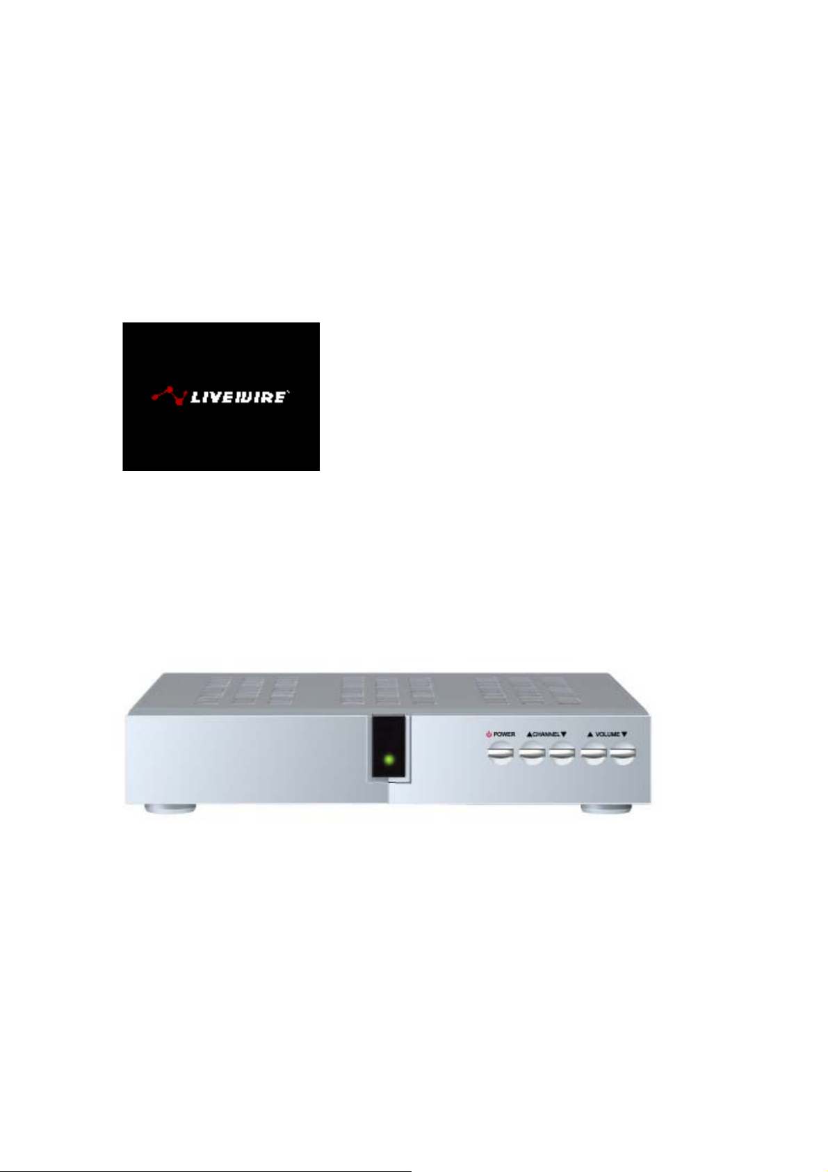
8. You should see the Livewire Start-Up Screen (Fig. 1) on the TV. Your Digital TV Software will
load and you are now ready to watch TV.
If you do not see the Livewire Start-Up Screen (Fig. 1) or live video, check your connections from
your TV and your cable source again.
If you still do not see the Livewi re Start-Up Screen (Fig. 1) or live video, ple ase refer to the Prob lem
Solving section (4.3) for the most common problems.
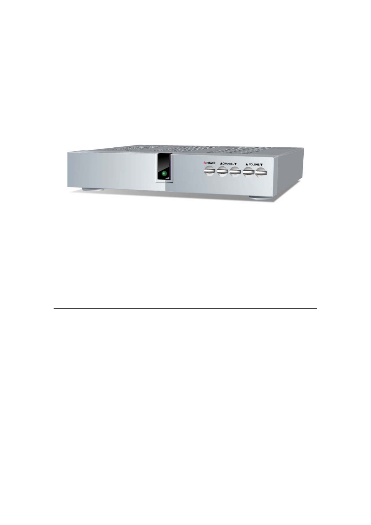
1.2 Front Panel
Smart Card Panel
Hidden Panel is behind Atlantic Digital Cable logo on the left front of your Digital Set-Top Box
LED Display
• Lights up Red when in Stand-By Mode
• Lights up Green when Power is on
Channel Up/Down Buttons
Navigates through the channel lineup
Volume Up/Down Buttons
Decreases or Increases the level of audio
Power Button
Switches Power On or into Stand-By Mode
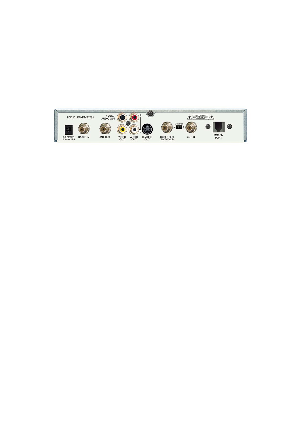
1.3 Rear Panel
DC POWER
Power Supply Input
CABLE IN
RF Input
( Coax Cable) This is used to connect the cable from the wall to the Digital Set-Top Box.
ANT OUT
RF Output
(Coax Cable) When the Digital Set-Top Box is in Stand-By mode, this output can be connected to a
TV/VCR directly.
DIGITAL AUDIO OUT
SPDIF Output
(Black RCA Connector) Used with a home cinema receiver or amplifier.
VIDEO OUT
Video Output
(Yellow RCA Connector) connects into a TV or VCR.
AUDIO OUT (R-L)
Stereo Audio Outputs
(Red and White RCA Connectors) Right (Red) and Left (White) connect into a TV, VCR or Hi Fi.
S-VIDEO OUT
Composite S-Video Output
(S-Video Connector) S-Video out to S-Video into a TV or VCR.
CABLE OUT TO TV/VCR
RF Output
(Coax Cable) This can be used to connect to a TV or VCR using a Coax Cable to the Digital
Set-Top Box.
CH 4-CH 3
Switch
Selects TV Channel 3 or 4 as the output channel to your TV. For optimum performance, it is
recommended that you set the CHANNEL output switch on the back of the Digital Set-Top Box to
channel 4.

ANT IN
RF Input
(Coax Cable) This can be used to connect a TV antenna using a Coax Cable to the Digital Set-Top
Box. When the Digital Set-Top Box is in Stand-By Mode, the original signal can be displayed
through the Digital Set-Top Box and into your TV or VCR directly (bypass) using the ANT OUT
connector.

1.3 Universal Remote Control

POWER In CABLE MODE switches Power On or into St and-By Mode. In all other modes turns the
power of that device On or Off.
CABLE Activates remote to control the Digital Set-Top Box (CABLE MODE).
TV Activates remote to control a TV (TV MODE).
VCR Activates re mote to co ntro l a VC R (V CR MO DE).
AUX Activates the remote to control an auxiliary device (AUXILIAR Y MODE).
0-9 Enters Channel Numbers and Passcode Numbers.
MENU Opens the MENU FEATURES screen of the MENU SYSTEM.
INFO Displays information about the current program in four dif ferent mo des.
VOL+/- Increases or decreases volume levels.
GUIDE Displays the PROGRAM GUIDE.
CH+/- Selects the previous and next available channels.
ARROWS (Up & Down, Left, Right) While using the MENU SYSTEM and PROGRAM GUIDE, arrows
will move(Up, Down, the onscreen highlight up, down, lef t, or right. W hile in INFO MODE, arrow s will
browse through the channel lineup and the next available program (Right). While inside a text window,
the Up and Down arrow s will scroll throug h the characters A-Z and num bers “0-9”. Use the L eft and Right
arrows to navigate through the text window.
OK Confirms a selection. In SURF MODE displays the OPTION MENU.
FAV+ (Red) Rotates Favorite Lists between All Channels, currently selected Theme and any of the
active Custom Favorite Lists.
HELP (Ye llow) Displays the HELP AND INFORMATION for the current screen.
DONE (Blue) Automatically selects “DONE” onscreen and saves any changes you have made to the
current screen.
MUTE Cancels audio.
PAGE UP Scrolls one page up in the PROGRAM GUIDE and MENU SYSTEM.
LAST Switches between current and previous channel, or through all actively monitored programs.
In the MENU SYSTEM and PROGRAM GUIDE, LAST returns to the previous screen.
MUSIC Changes Channel Lineup to include only Digital Music Channels.
PAGE Scrolls one p age down in the PROGRAM GUIDE and MENU SYSTEM.DOWN

EXIT Returns video to full screen from any INFO, MENU SYSTEM or PROGRAM GUIDE screen.
RECORD Sets a VCR to Record.
P AUSE Instructs a VCR, DVD or CD player to Pause.
PLA Y Instructs a VCR, DVD or CD player to Play .
REWIND Instructs a VCR, DVD or CD player to Rewind.
STOP Instructs a VCR, DVD or CD player to S top.
FAST FORWARD Instructs a VCR, DVD or CD player to Fast Forward.
2 View Programs
2.1 Program Information
INFO MODE
You can view information about the current program by pressing the "Info" button on the remote
control. Each time you press the button, more information about the program will be displayed
onscreen. To exit INFO MODE, continue to press the “Info” button until the information screens
disappear, or press “EXIT” at any time.
INFO 1 MODE
Displays the following information:
• Channel Name
• Channel Number
• Program Name
• Current Date and Time

• Start and End Times
INFO 2 MODE
Displays the following information:
• Channel Name
• Channel Number
• Current Date and Time
• Program Start Time
• Program End Time
• Program Theme
(If Available)
• Program Rating
(If Available)
• Program Name
• Program Time Remaining
INFO 3 MODE
Displays all of INFO 2, plus:
• Program Description
• Transparent Window
2.2 Program Navigation
NAVIGATING INFO MODE

Use “CH +” or “CH -” to tune to the next or previous available channel. The screen w ill remain in the
INFO MODE you have selected. To exit INFO MODE, continue to press the “Info” button until the
information screens disappear, or press “EXIT” at any time.
NOTE: Even if you are not in INFO MODE, your screen will display information about the current
program each time you change the channel. This information will briefly remain onscreen and then
automatically disappear.
In any active INFO MODE you can use the “Up” and “Down” arrows on your remote to scroll
through the channel lineup and view program information without changing your current channel.
This way, you can evaluate what is on other channels without leaving your current program.
Use the “Right” arrow button to preview information for the next program on your current channel.
Use the “Up” and “Down” arrow buttons to scroll through the channel lineup for information on all
programs in the next time slot. Use the “Left” arrow button to return to the current time slot.
While viewing program information, press “OK” to select and tune to a program. If you select “OK”
for a program in the next time slot, your Digital Set-Top Box will tune immediately to that channel.
NOTE: You can use the Program Guide (Section 2.3) to set timers for future programs in advance.
With a timer set, your Digital Set-Top Box will automatically tune to that program when it becomes
available.
Use numbers “0-9” on your remote control to enter a specific channel number, and your Digital
Set-Top Box will tune to that channel after a brief delay. Press “OK” to tune to a channel manually,
without a delay.
2.3 Program Guide
USING THE PROGRAM GUIDE
Press “Guide” on your remote control to display a list of all available channels and their programs.
Use the arrow buttons to move the orange highlight onscreen and choose a program. Make a
selection by pressing “OK”.
Once you make a selection, you will be given a full description of the program and the following two
options: VIEW NOW for current programs or SET TIMER for future programs to view the program
when it becomes available.
UNDERSTANDING THE PROGRAM GUIDE

The Program Guide is divided into four sections.
The top left corner of your screen displays an INFO WINDOW that contains the following
information about the program that you have highlighted:
• Channel Number
• Program Start Time
• Program End Time
• Program Theme
• Program Rating (If Available)
• Channel Name
• Program Name
• Short Program Description
• Current Favorite List Name
The top right corner of your screen displays a VIDEO MONITOR of the tuned program, along with
the following information:
• Current Channel Number
• Current Short Channel Name
• Current Time
The LEFT COLUMN lets you scroll through the channels available in your current channel lineup
and displays all programs currently playing. The left column displays the following information:
• Current Date
• Channel Numbers
• Short Channel Names

• Current Program Names
The RIGHT COLUMN displays the upcoming programs available on the currently highlighted
channel.
Scroll down to show all the programs scheduled for the day or select DAY SHIFTER (see p.15) to
quickly jump ahead 24 hours. The right column displays the following information:
• Date of the Highlighted Program
• Program Start Times
• Program Names
NAVIGATING IN THE PROGRAM GUIDE
Each time you activate the Program Guide by pressing “Guide” on the remote control, it begins by
displaying the information about the current channel and program you are tuned to. Note that the
VIDEO MONITOR corresponds to the description in the top left INFO WINDOW.
Use the "Up" and "Down" arrows on your remote control to scroll through the channel lineup in the
LEFT COLUMN. The RIGHT COLUMN displays future programs available on the channel that you
have highlighted in the LEFT COLUMN.
Use the “Right" arrow on your r emote c ontrol to brow se inside the RI GHT CO LUMN . Use the " Up"
and "Down" arrows to scroll through future programs. You can return to the LEFT COLUMN by
pressing the "Left" arrow at any time.
To scroll more quickly through the Channel Lineup, use the “Page Up” or “Page Down” button on
your remote control to scroll one page at a time.
You can also use the numbers “0-9” on your remote control to enter a specific channel number, and
the Program Guide will highlight that channel after a brief delay.
NOTE: Depending on program length, the RIGHT COLUMN may not immediately display all future
programs. However, when you move the cursor into the RIGHT COLUMN, your Digital Set-Top
Box will access and display all future program information. In some cases, the Digital Set-Top Box
will temporarily suspend the VIDEO MONITOR while accessing program information. Once the
data has been updated, video will return.

DAY SHIFTER
When you move the cursor inside the RIGHT COLUMN, the list will begin with the current program.
From this position, use the "Up" arrow on your remote control to start the DAY SHIFTER feature, or
press the “Last” button on your remote control to automatically highlight the DAY SHIFTER. Once
the current date is highlighted, use the "Right" arrow to skip ahead 24 hours from the current time.
Each time you press the "Right" button, the display will skip ahead another 24 hours. Use the “Left”
arrow to return to the current date.
At any time while using the DAY SHIFTER, use the "Down" arrow to browse through the programs
available that day.
NOTE: To return to the DAY SHIFTER feature once you have started browsing in the future
program list, you can select the “Last” button on your remote control. You can also start over by
returning to the LEFT COLUMN by pressing the “Left” arrow and return to the current day’s
programming.
TUNING TO CURRENT AND FUTURE PROGRAMS
At any time in the program guide, press "OK" on your remote control to display a full description of
the program you have highlighted.
If you select a CURRENT PROGRAM, you will be given the option to tune immediately to that
program. Choose "VIEW NOW" onscreen by pressing "OK" on your remote control.

If you select a FUTURE PROGRAM, you will be given the option to set a timer so that you can view
the program when it begins. Choose "SET TIMER" onscreen by pressing "OK" on your remote
control. A TIMER ICON will then appear next to the program for which you have set a timer. Your
TV will automatically tune to this program when it begins.
If you do not wish to view the current or future program, return to the Program Guide by pressing
"Last" on your remote control.
You can cancel a timer at any time. Highlight the program for which a timer has been set and press
"OK" on your remote control. You will then be given the option to cancel the timer for that program.
Choose "CANCEL" onscreen by pressing "OK" on your remote control.
2.4 Options
USING THE OPTIONS SCREEN
While viewing any program, you can access the OPTIONS screen directly by pressing “OK” on your
remote control. Available program options include: Additional Audio, Additional Video and
Subtitles.
TIP: You can use the blue “Done” button on your remote control to automatically select “DONE”
onscreen, without having to navigate to it.
Also, you can use the yellow “Help” button on your remote control to access the Help and
Information Screen for any page without having to navigate to the “HELP” button onscreen.
ADDITIONAL AUDIO AND VIDEO
If an additional audio and/or video feed is available for the program you are viewing, you will see
icons for ADDITIONAL AUDIO and/or ADDITIONAL VIDEO on the left side of the screen. Activate
the OPTIONS screen by pressing “OK” on your remote control. Then use the “Arrow” buttons on

your remote control to navigate and select the available option. Select “DONE” onscreen to activate
changes.
The changes will only affect your currently viewed program, and will default back to normal once
the program is complete.
TIP: Press the “FAV+”(Red) button on your remote control to rotate through your favorite lists.
When you activate this feature, you will switch between All Channels and if active, your currently
selected Theme and any of the eight Custom Favorite Lists. (Section 3.1)
2.5 Ordering Pay-Per-View
ORDERING PPV MOVIES
Your Digital Set-Top Box allows you to purchase pay-per-view events directly onscreen. When you
tune to a PPV Channel you will be asked to press "OK" to buy the program now. Once you confirm
your purchase, your account will be charged immediately and the program will be available at its
scheduled start time.
Also, you are able to purchase in advance the next available pay-per-view event at any time before
and up to 20 minutes after the start time. Press the "Right Arrow" on the remote to scroll to the next
event and you will be instructedon-screen to purchase the next event.
NOTE: Once the purchase window of 20 minutes has expired you will only be shown the next event
available.
TIP: If you are considering purchasing a PPV Program at a future time or date, use the Program
Guide to set a timer by highlighting the future PPV Program and pressing “OK” on your remote
control. You will then be given the option to set a timer. Press “OK” on your remote control to
choose "SET TIMER" onscreen. Please note, this will only set a timer and NOT purchase the event.
3- Menu Features

MAIN MENU
Access the Main Menu at any time by pressing the “MENU” button on the remote control.
MENU FEATURES
• Portal Cable Mágico (Section 2.1)
• Program Guide (Section 2.2)
• Favorites
• Parental Controls
• Timers
• System Menu
TIP: Press the blue “Done” button on your remote control to automatically select “DONE” on the
current screen that you are viewing and sa ve any cha nges that yo u hav e made to the curre nt
screen. Please note that using the “Last” button will only ret urn you to the previou s menu and N OT
SAVE any changes you have made on the current screen.
3.1 PPV Status
With the PPV Status feature you can keep track of the PPV events that
have been purchased on your account. The menu will list the event
name, date of the event, starting time, and the purchase price.
This feature is useful to confirm that a PPV event has been purchased and also keep track of of
what events are being purchased and viewed in your household.
3.2 Favorites/Themes

SELECT FAVORITE LIST OR BROWSE BY THEME
• Display All Channels: Quickly reset your current mode to include all available channels.
• Channel Themes: Choose from a variety of different themes for browsing, such as Movies, Kids,
or Sports.
• Edit Current Favorites: Opens the EDIT FAVORITE Menu Page, where you can change the name
or channel lineup of any of your eight custom favorites list.
NOTE: If you are browsing in All Channels or Channel Themes and would like to edit a custom
favorite channel list, you must first highlight the custom favorite channel list you would like to edit.
CHANNEL THEMES
You can choose from a variety of different pre-set themes for browsing, such as Movies, Kids, or
Sports. Select "DONE" onscreen to confirm your selection.
EDIT FAVORITE
To change the name of a favorite list, select “Edit Name” onscreen. A cursor will then appear inside
the TEXT WINDOW. Use the “Up” and “Down” arrow buttons on your remote control to scroll
through the alphabet. Press the “Right” arrow on your remote control to move to the next letter.
Press the “Left” arrow on your remote control to return to the previous letter. You can also include
numbers 0 through 9 and a “space” in the new name. When finished, press the “Right” arrow on

your remote control to exit the TEXT WINDOW and highlight the “SAVE” button onscreen. Press
"OK" on your remote control to save changes to the name.
You can choose up to 30 channels for each Custom Favorite List. Scroll through the channel lineup
using the “Page Up/Down” buttons onscreen or on your remote control. Select “DONE” onscreen to
confirm channel lineup choices.
TIP: You can use the red “FAV+” button on your remote control to cycle through CUSTOM FAVORITE
LISTS in the EDIT FAVORITE screen.
3.3 Parental Controls
RESTRICT ACCESS TO PROGRAMMING BY CHANNEL OR PROGRAM RATING
PARENTAL CONTROLS ACCESS
To access the PARENTAL CONTROLS screen, enter your System PIN-Code using numbers “0-9”
on your remote control, then select “ENTER” onscreen.
NOTE: The first time you set the System PIN-Code, the numbers will appear in the TEXT WINDOW.
The next time, the System PIN-Code will appear as asterisks.
TIP: You can use the blue “Done” button on your remote control to auto-matically select “CANCEL”
onscreen, without having to navigate to it.
PARENTAL CONTROLS
Parental Control Status: Turns parental controlled channels and rating blocks on or off.
Block Channels: Opens the CHANNEL BLOCK screen that lists all available channels. You can
select up to 30 channels to be blocked from view.
Block Ratings: Opens the RATINGS BLOCK screen that lists all available program ratings. You
can specify that all programs of any selected rating will be blocked from view.

Change PIN-Code: Opens a screen that allows you to set a new PIN-Code.
You may also wish to consider the following General Settings:
• Lock Set-Top Panel: Lock the Digital Set-Top Box front panel buttons.
Select “DONE” onscreen to confirm Parental Control status and return to the MENU FEATURES
screen.
BLOCK CHANNELS
Scroll through the chann el lineup and choos e up to 30 ch annels to b lock from view . Select “D ONE”
onscreen to confirm blocked channels and return to the PARENTAL CONTROLS main screen.
BLOCK RATINGS
You can specify that all programs of any selected rating will be blocked from view. Select the
ratings of the programs that you would like blocked. Select “DONE” onscreen to confirm blocked
ratings and return to the PARENTAL CONTROLS main screen.
3.3 Timers
REVIEW SET-TIMERS AND CREATE MANUAL ON/OFF TIMERS
With this screen, you can review the number of timers that you have set through the program guide.
You have the ability to cancel any timer that is in the list. This may come in handy if you are trying to
set a new timer and have received a notice that a timer has been previously set and would like to
cancel the old timer.

SET MANUAL TIMER
The SET-MANUAL TIMER screen allows you to set an ON/OFF timer on your Digital Set-Top Box.
You can use this feature, if you have turned your Digital Set-Top Box off and would like to have it
turn back on at a specific date and time to be available to record a program with a VCR.
First press the "OK" button on-screen and use the "Up" and "Down" arrows on the remote control to
scroll through the channel lineup and enter the three digit channel number that you would like the
box to tune to when is turns on.
3.4 System Menu
PERSONALIZE YOUR DIGITAL SET-TOP BOX BY USING THE SYSTEM MENU
The Sytem Menu features menu screens that allow you to customize your Digital Set-Top Box,
Change your System PIN-Code and view information about your System Software. Access the
System Menu at any time by pressing the “MENU” button on the remote control. Scroll down the
menu list and select SYSTEM MENU by pressing the “OK” button on the remote control.
SYSTEM MENU FEATURES
• General Settings
• System PIN-Code
• Installation
General Settings 1 and 2: This scollable menu allows you to specify your preferences for Screen
Dimensions, Menu Language, Audio Language and Subtiling Language.
System PIN-Code: Opens a screen that allows you to set a new PIN-Code.
Installation: Through the Installation Sub-Menu you can view detailed information about the system,
Smart Card, tuning and also reset your system to the factory defaults.

GENERAL SETTINGS 1
SCREEN FORMAT:
To set your preference for the dimensions of video that you would like to
receive on your TV, use the “Arrow” buttons on your remote control to
select one of the 3 following options:
• Standard 4:3 (Standard Screen): Select this option if your TV is standard
format
• Widescreen 16:9 :Select this option if you have a widescreen TV and
would like widescreen video to display full screen if it is available.
• Letterbox 4:3: Choose this option If you prefer the Digital Set-Top Box to
convert 16:9 video if available to 4:3 by default.
DEFAULT LANGUAGE:
Use the “Arrow” buttons on your remote control to select the text language that you would like to
appear on the interactive TV screens.
NOTE: Use the “Page Up/Down” buttons onscreen or on your remote control to access GENERAL
SETTINGS 2 or select “DONE” onscreen to confirm your preferences.
GENERAL SETTINGS 2
PREFERED AUDIO LANGUAGE: Use the “Arrow” buttons on your remote control to select the
audio language that you prefer to hear with your video programming if available.
NOTE: You can switch to any audio language that may be available for a program by using the
OPTIONS screen while you watching a program (Section 2.6). This will only effect the current
program and not change your preferred audio language in GENERAL SETTINGS.

SUBTITLING: Use the “Arrow” buttons on your remote control to first turn Subtitling ON or OFF. If
you choose ON then the subtitle text will appear over your video in the language that you specify
here.
NOTE: You can switch to any subtitle language that may be available for a program by using the
OPTIONS screen while you watching a program (Section 2.6). This will only effect the current
program and not change your preferred subtitle language in GENERAL SETTINGS.
Select “DONE” onscreen to confirm general settings and return to the SYSTEM MENU.
SYSTEM PIN-Code
To change your PIN-Code, first enter your current PIN-Code using numbers
“0-9” on your remote control, then select “ENTER” onscreen.
You will then be asked to enter your new PIN-Code twice to confirm your change.
Use the numbers “0-9” on your remote control, then select “ENTER” onscreen
each time. After the second time your PIN-Code will be changed. Select
"CANCEL" onscreen to return to the SYSTEM MENU and not change you PIN-Code.
NOTE: You may not use 4 equal digits, for example, "0000". Please keep you
PIN-Code in a safe place. If you have forgotten or lost your PIN-Code, please
check in with customer service.
INSTALLATION
VIEW SYSTEM INFORMATION
This information will be useful if it becomes necessary to contact the customer service for
assistance. Access the Installation Menu at any time by pressing the “MENU” button on the remote
control. Scroll down the menu list and select SYSTEM MENU by pressing the “OK” button on the
remote control. Scroll down again and select INSTALLATION by pressing the “OK” button on the
remote control.
INSTALLATION SUB-MENU FEATURES
• System Info

• Smart Card
• Tuning Status
• Reset System to Factory Defaults
SYSTEM INFO 1, 2 and 3
The information on these screens indicate details about your Digital Set-Top Box, System Software,
Data Collection, Number of TV Channels, and your System Clock.
NOTE: Use the “Page Up/Down” buttons onscreen or on your remote control to access GENERAL
SETTINGS 2 and 3 or select “DONE” onscreen to return to the INSTALLATION sub-menu.
SMART CARD
This menu provides details about the smart card currently inserted in your Digital Set-Top Box. It is
recommended that you never remove your Smart Card unless asked to do so by a customer
service representative. Removal of your Smart Card will result in loss of service. Your Digital
Set-Top Box is paired to the specific Smart Card that was given to you at the time of installation and
will not work in any other Digital Set-Top Box.
TUNING STATUS

With this screen you can quickly see if your Digital Set-Top Box is locked to the correct frequency.
If the signal is locked you will see the “LOCKED” icon on-screen.
RESET SYSTEM
To reset your system to the original factory defaults, enter your PIN-Code
using the numbers “0-9” on your remote control, then select “RESET”
onscreen. You will be asked to confirm your choice.
WARNING: This will erase all customization, including: PIN-Code,
Favorites, Parental Controls, Default Languages and other General
Settings.
Press “CANCEL” onscreen to return to the DIAGNOSTICS screen without resetting the system.
TIP: You can use the blue “Done” button on your remote control to automatically select “CANCEL”
onscreen, without having to navigate to it.
4 -Trouble Shooting
4.1 Onscreen Help
ACCESS HELP AND INFORMATION FOR EACH MENU SCREEN
Each MENU SCREEN has a screen-specific help and information page. Access
this page at any time by pressing the “HELP” (Yellow) button on your remote

control, or by using the arrow buttons to select “HELP” (Yellow) located
at the bottom of each MENU SCREEN.
Select “DONE” onscreen to exit HELP AND INFORMATION and return to the MENU
SCREEN you came from.
TIPS: Press the yellow “Help” button on your remote control to display the
HELP AND INFORMATION for the current screen you are viewing.
Use the “Last” button on your remote control to return to the previous menu
screen without saving changes.
Use the “EXIT” button on your remote control to return video to full screen
from any INFO, MENU SYSTEM or PROGRAM GUIDE screen without saving changes.
4.2 Message Screens
RECEIVE CHANNEL BLOCK AND TROUBLE- SHOOTING MESSAGES ONSCREEN
Your Digital Set-Top Box can diagnose most problems that may occur with the
video and audio signal, as well as the status of the Smart Card that controls
your access to programming.
Each MESSAGE SCREEN will provide a tip on what to do in case of trouble.
Also, channels or programs that are BLOCKED display a notification message.
MESSAGES you may receive onscreen may include the following:
• Cable Signal Problem
• Smart Card Not Inserted
• Smart Card Not Paired
• Smart Card Never Paired
• Smart Card Com Error
• Smart Card Invalid
• Smart Card Expired
• Smart Card Suspended
• Smart Card Blacklisted
• Access Denied
• Channel Deleted
• Video Not Ready
• Audio Not Ready
• System Data Not Ready
• Parental Lock

MESSENGER SCREENS
Specific messages regarding your account, line-up changes, temporary
outages or
weather patterns can be transmitted directly to your Digital Set-Top Box by
way of MESSENGER SCREENS.
Once read, some MESSENGER SCREENS are temporary, and go away after a few seconds, or
are removed by pressing the “OK” button on your remote. Others may require you to contact your
service and address certain issues in order to be removed.
4.3 Problem Solving
REPAIR SERVICE
If you need help installing your Digital Set-Top Box, cannot solve Digital Set-Top Box problems
after you have reviewed the following section,
are having trouble with your cable signal, or have forgotten your PIN-code, please contact your
customer service representative.
PROBLEM
POSSIBLE CAUSE
SUGGESTIONS
No Red or Green LED lights appear on the front panel display of your Digital Set-Top
Box.
Your box is not plugged in properly.
Make sure the power cord is plugged in correctly and the power outlet is working
properly.
The Digital Set-Top Box does not respond to your Remote Control.
1. The Digital Set-Top Box is in standby mode.
2. Something, such as furniture, is blo ckin g th e path b e twee n th e Remot e Co ntro l
and the Digital Set-Top Box.
3. The batteries in the Remote Control need to be replaced.
Check that nothing is blocking the front panel of your Digital Set-Top Box. In CABLE
MODE, Press the POWER button on the Remote Control. This will bring the Digital Set-Top
Box out of standby mode.
If there is still a problem, try to operate your Digital Set-Top Box using the front
panel buttons.
If this does not work, your Digit al Set-Top Box may be at fault. But if this works, y ou
should replace the batteries on your Remote Control. If replacing the batteries properly
(check the + and - position) doesn’t work, then your Remote Control may have problems.

The front panel displays a Green LED Light, but nothing is displayed on the TV.
The Digital Set-Top Box is not hooked up properly to your television set.
If your system is connected by Coax Cables, switch your TV to the channel you have
selected as its channel for the Digital Set-Top Box. NOTE: If you have not yet manually
tuned your TV or turned your TV on, you need to do this first.
 Loading...