

Page 1
XR5
Page 2

© 2002 - 2008 Digital Monitoring Products, Inc.
This information is subject to change without notice.
While the re alarm horns, strobes, or sirens are sounding,
While the alarm bell or siren is sounding, turn the keyswitch
ALARM SILENCED
While the alarm bell or siren is sounding, enter the
ALARM SILENCED
followed by the
The panel must be silenced before it can be reset. Follow
Turn the keyswitch to the ENABLE position and press the
MENU? NO YES
displays.
YES
followed by the
Press any top row key. The sensor turns off then
followed by the
ve seconds for the panel to reset.
Page 3

XR5 User’s Guide
for XR5 Fire Command™ Panels
Table of Contents
Section
Page
Section
Page
About this User Guide
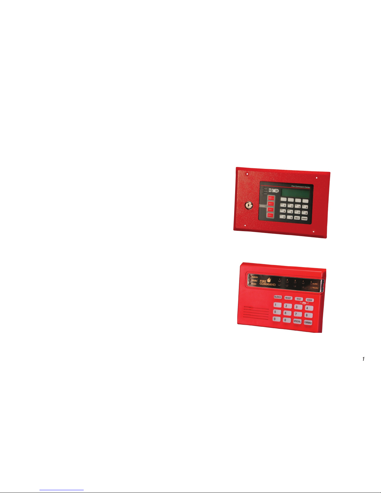
About the 630F LCD Keypad
The 630F LCD Keypad
8
8
9
Zone Event Displays
Zone Bypass Event Displays
Auto Recall Event Displays
About the 692F LED Keypad
Command key
Zone Alarm and Trouble LEDs
Alert Tones
Testing the System
Page 4
XR5 User’s Guide
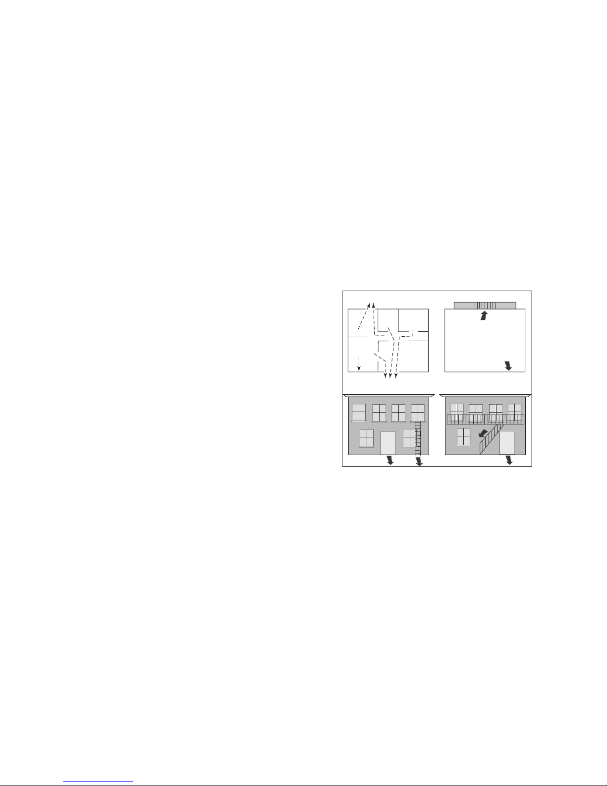
Second Floor
Building Front
Building Back
First Floor
Fire Escape
Window Ladder
The best way to survive a re or other emergency is to get out
early. A re alarm system installation, with smoke and carbon
The National Fire Protection Association recommends that you
establish an emergency evacuation plan to safeguard lives in
encounter while exiting the building such as large furniture or
emergency personnel are likely to be working. A neighbor’s
occupants safely exited. NEVER ENTER A BURNING BUILDING.
Page 5
XR5 User’s Guide
The XR5 Fire Command™ system has been designed with your
safety in mind using the latest in computer technology.
You can perform system functions such as silencing bells by
code at any time.
About this User Guide
This User Guide discusses features of the XR5 Fire Command™
system using the 630F LCD keypad and the 692F LED keypad.
The guide is divided into two sections that discuss using the XR5
system with either the LCD keypad or the LED keypad. Turn to
Page 6
2
XR5 User’s Guide
TEST Ke y
YES to begin the re drill. Press NO to return to the status
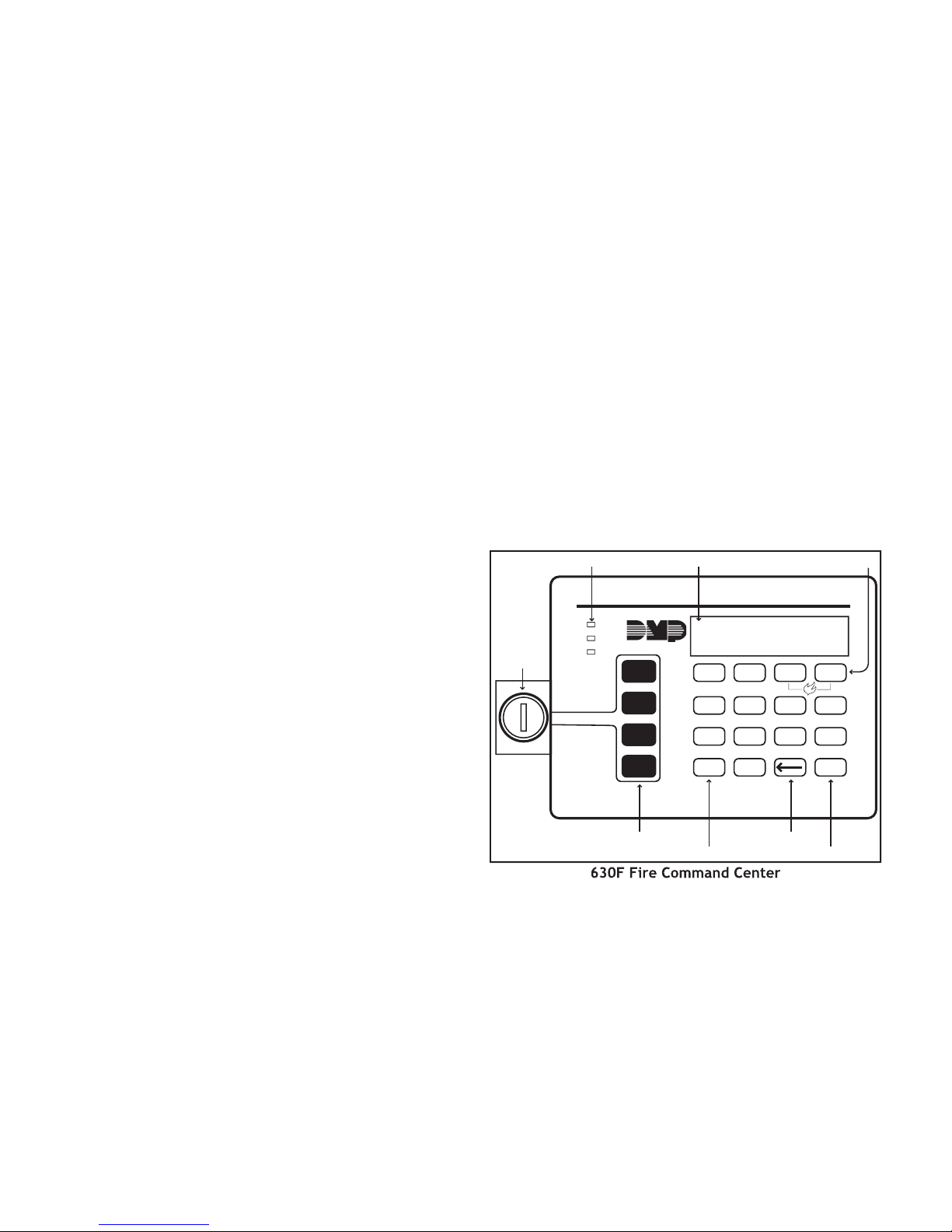
About the 630F LCD Keypad
The 630F LCD keypad has many features to allow you to properly
operate the system and review previous event history. The
can access the functions needed to operate the system. See
following pages list speci c and common operational features.
The
All of the 630F Fire Command Center keys, except the four
function keys, can be used at any time without turning the
operations.
The following descriptions and illustration highlight the speci c
The 630F Fire Command Center is designed with four keys on
can quickly perform vital functions using these four keys.
Page 7

XR5 User’s Guide
3
The 630F keyboard provides three LEDs to indicate the system
status.
remains ON steady when both AC and battery input
ashes for 1/2 second intervals when battery input is low.
TROUBLE LED
turns ON when any trouble is displayed in the
status list, such as AC, battery, phone line, transmit, NAC, or
ALARM LED
is ON when any alarm currently displays in the
status list. This LED is OFF when no alarm is currently displayed
These keys allow you to choose an option by pressing the Select
The keypad uses a backlit LCD display and plain English text to
show events occurring on your system.
These keys allow you to enter the code number when using the
system.
The Back Arrow key allows you to back up through the list of
functions in the User Menu, or make corrections when enter ing
The COMMAND key allows you to advance through the options
on the keypad display, and enter information into the system.
This remains on steady as long as your re system is connected
service department. Should the battery power become low,
Page 8

4
XR5 User’s Guide
The LCD displays the keypad’s current address. The information
cannot be changed by the user. Press the Back Arrow key to exit
function.
The keypad model number, rmware version, and date display,
Zone
A zone refers to one or more re system devices. For example,
smoke detectors on the east side of the premises can be
Your system can also be programmed to send alarm and trouble
system on the keypads. The Status List displays alarm or trouble
conditions on zones and trouble conditions that occur with AC
or battery power or the phone lines. If more than one alarm or
The User Options allow you to make adjustments to your keypad
To access the User Options portion of the keypad, press and
Arrow key to exit.
If the brightness level is lowered, it temporarily reverts
Volume level
conditions, the volume is always at maximum level. At SET
VOLUME LEVEL, use the left Select key to lower the keypad
volume. Use the right Select key to raise the volume.
Page 9

XR5 User’s Guide
This display indicates that re protection devices, phone lines
A re, supervisory, or auxiliary zone has been tripped. Your
system may sound the re bells, strobes, and any other response
A user has silenced the re bells by entering the code or by
A supervisory alarm has occurred and is in the Status List for
A zone has been disabled by the system due to repeated trips.
The system requires you to enter the user code. As you enter
TRY AGA IN
The user code you have entered is not recognized by the
system. Check the code and try again.
You receive this message if you enter an incorrect user code a
second time, after receiving the Try Again message.
There is a problem with the phone line connected to your
system. Call for service as soon as possible.
TROUBLE
There is a problem with a protection device or system
component. This display is accompanied by a description of the
There is a problem on the system. Call for service.
Page 10

XR5 User’s Guide
Your keypad also contains a small speaker that alerts you about
events as they occur on your system.
Trouble tone
your system. Press a Select key to silence.
While the alarm bell or siren is sounding, turn the keyswitch to
station and does not reset any alarmed devices.
While the alarm bell or siren is sounding, enter the user code.
The keypad displays
ALARM SILENCED
To silence the trouble sounder in the keypad, turn the keyswitch
To silence the trouble sounder in the keypad, press any Select
Many of the features of your system are accessible in the User
Menu you can access from the keypad. The menu requires you
To access the User Menu:
MENU? NO YES
displays.
YES
scroll down through the list of menu options.
The list shows the User Menu options in the order they appear
Page 11

XR5 User’s Guide
Menu Option
Tests the system siren, communication
Allows you to practice re drill
evacuations.
Allows you to change the user code.
Allows you to view or print the last 16
events that occurred on your system.
The following pages detail each user menu item and provide
Sensor Reset momentarily removes power to smoke
Make sure all smoke is cleared from around the smoke detectors
occurring again.
Access the User Menu.
When
displays, press any Select key.
The keypad displays
for ve seconds
followed by
The keypad returns to the status display.
Page 12

XR5 User’s Guide
communi cation to a central station. The System Test function
Access the User Menu. Press the COMMAND key until
displays.
during a two second bell test,
or
BATTERY - TRBL
to indicate
*
TRANSMIT TEST
ATTEMPT NO : 1
4) *
TRANSMIT OKAY
or
TRANSMIT FAILED
to show the
TEST END
You can cancel the transmit test by pressing the
* The transmit tests are not applicable for local
systems.
Allows you to practice re drill evacuations.
Access the User Menu. Press COMMAND until
YES
YES
enter at the keypad.
The user code must always have 4 digits.
Access the User Menu.
The keypad displays
4.
The keypad displays
ALREADY IN USE
enter a different user code.
Page 13

XR5 User’s Guide
Allows you to review up to 16 past events that
occurred on your system in the order of their occurrence.
The system records two event types:
service.
- Records problems with the system’s hardware
components.
The system’s memory can hold up to 16 events. After 16 events
cleared.
Access the User Menu.
appears.
Zone
# FIRE ALARM
The display actually contains three separate sections.
#
- Records the zone number. Press the Select key under the
zone number to display the custom zone name programmed into
- This is the type of zone on which the activity occurred.
There are three possible zone types you may see on your
AUX1 - Auxiliary 1
ALARM
- This is the event that occurred. There are 3 event
ALARM
TROUBLE RESTORE
Zone Bypass Event Displays
# BYPAS
This zone has been bypassed by the system.
- This zone has been reset by the system.
custom zone name programmed into the system.
Page 14

XR5 User’s Guide
The display contains two separate sections.
- The type of condition that occurred on your system.
The status regarding that condition.
TROUBLE
Auto Recall Event Displays
Your system sends periodic recall (test) reports to the central
station to test the communications link. Each successful test
AUTO RECALL
Page 15

XR5 User’s Guide
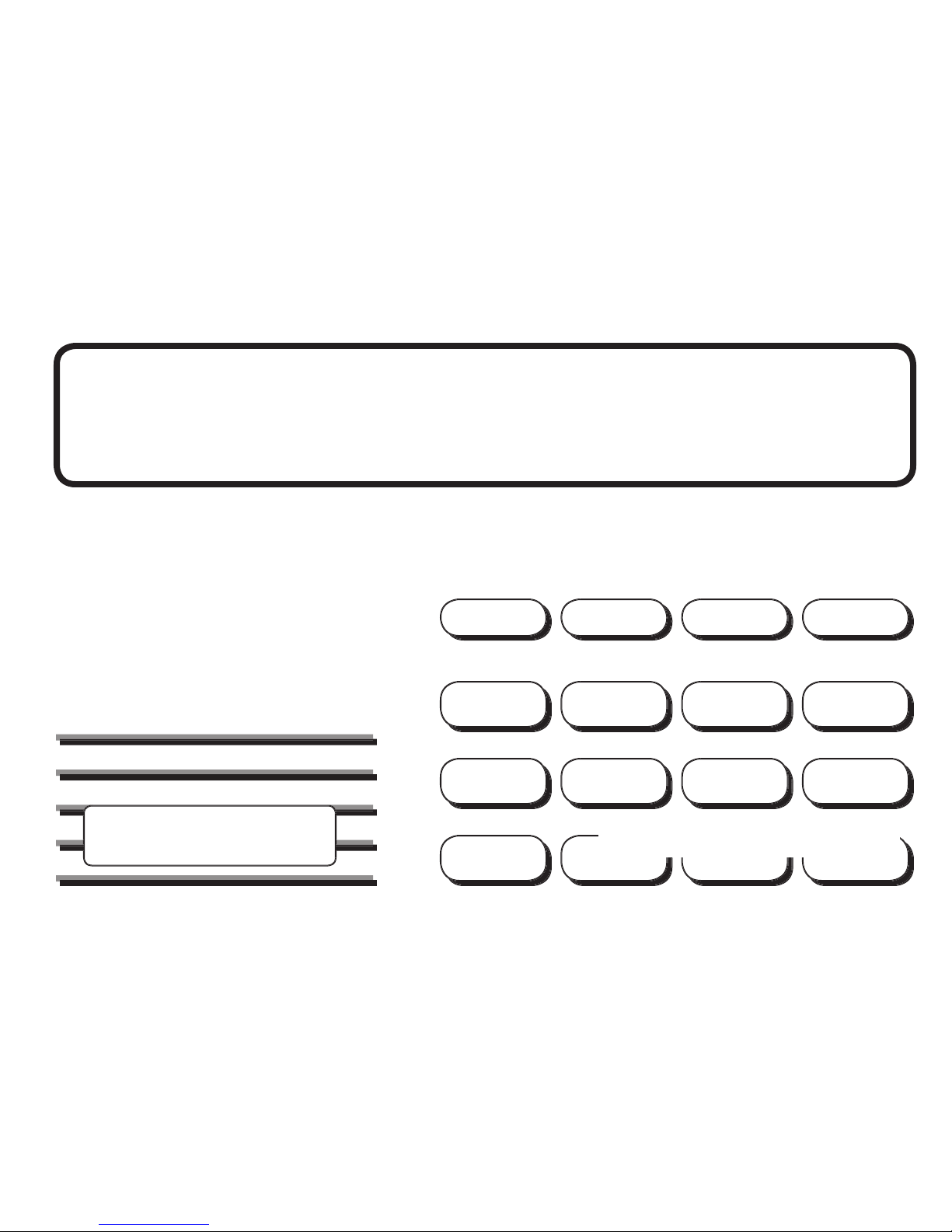
About the
This device has been placed at locations throughout the
AABB CC DD EE FF GG HH II JJ KK LL
VVWW XXMM NNOO PPQQ RR SS TTUU
YY ZZ
9 0
2 3
4
5 6 7 8
COMMAND
1
SILENC ED
TROUBL E
POWER
ALARM
TROUBL E
1 2 3 4
5
SILEN CE RESET TEST CODE
SPECI AL
System LEDs
Zo
ne
Alarm
LEDs
Backlit Data
Entry Keys
Function
Keys
COMMAND Key
SPECIAL Key
Zone
Trouble
LEDs
There are four keys under the display called the Function keys.
These keys allow you to perform system operations by pressing
one key, followed by the entry of a user code.
TEST Ke y
These keys allow you to enter your user code and other
key
The COMMAND key allows you to complete a data entry
function.
The Fire Command Center incorporates three LEDs to indicate
Yellow Silence d LED
when the bells are silenced manually from the keypad or
when a Sensor Reset is performed or if the alarm sounds
Page 16

XR5 User’s Guide
Yellow Trouble LED
when the system is unable to send a report to your central
station or when the phone line is in a bad condition.
when the system is operating correctly.
(1 second on, 1 second off) when there is a problem with
when AC and battery power are okay.
Zone Alarm and Trouble LEDs
steady during an alarm condition.
when the zone has restored to normal and a Sensor Reset
Yellow Zone Tr ouble L EDs
when the zone restores to normal.
Alert Tones
indicates a trouble condition on the system or a
re zone. Follows the operation of the bells. Pressing any key
silences a steady alert tone.
is emitted each time a key is pressed or a valid
function is entered.
4 Short Beeps
The keyboard on the 692F lights any time a key is pressed or the
system alarm and the keypad sounder. You may also use the
key to silence the bells during the Fire Drill function.
key and enter the user code to reset a zone
This resets all zone alarm LEDs and momentarily drops power to
TEST
TEST
function key and enter the user code to initiate
This test rings the panel bells for 2 seconds, checks the battery
charge level, and sends a system test report to the central
station on monitored systems.
To change the system user code, press
The user code must always be 4 digits.
Page 17

XR5 User’s Guide
Testing the System
This assures you that the system is working correctly and
central station are tested.
You can also initiate a System Test by pressing the TEST function
4-digit User Code.
enabled.
station. The keypad beeps to con rm the Fire key entry.
key and entering the user code initiates
The Fire Drill sounds the alarm bells and keypad sounder for the
zero (0), the Fire Drill continues until the bells are silenced by
entering a code. No keypad LEDs are turned on and no reports
zone glows red on the 692F.
To manually initiate a Fire Alarm, press and hold the
TEST
sounds.
zone restores to normal.
You can also initiate a Sensor Reset by pressing the RESET
function key followed by your User Code.
Page 18

XR5 User’s Guide
A
ALARM LED (630F)
Alert Tones (LED)
CODE Key (LED)
COMMAND Key (LCD)
4
COMMAND Key (LED)
Auto Recall
Zone
Zone Bypass
TROUBLE LED
Testing the System (LED)
TEST Key (630F)
TEST Key (LED)
Tones (LCD)
Trouble tone
TROUBLE LED (630F)
Zone Alarm and Trouble LEDs (LED)
Page 19

This page intentionally left blank.
Page 20

8105
 Loading...