

Page 1
734B Access
Control Module
INSTALLATION AND PROGRAMMING GUIDE
Page 2

Page 3

TABLE OF CONTENTS
About the 734B .......................................... 1
Power Supply ......................................................... 1
Zone Terminals ...................................................... 1
Annunciators .......................................................... 1
Indicator LEDs ....................................................... 1
Form C Relay ......................................................... 2
Programming Connection ................................ 2
Keypad In and Out Connections ................... 2
PCB Features ...............................................3
Install the 734B ...........................................4
Wire the Access Control Lock ........................ 5
Isolation Relay (optional) ................................. 7
Install the 333Suppressor ............................... 8
Wire the Zone Terminals ................................... 9
Connect a Magstripe Reader ..........................11
Set the 734B Address .......................................14
Program the Panel .................................... 17
Device Setup ........................................................17
Device Number ..................................................................17
Device Name .......................................................................17
Device Type .........................................................................18
Communication Type .......................................................18
Program the 734B ....................................19
Program BINs as User Codes (Process at
Panel) .....................................................................20
Program BINs Locally (Process Locally) ... 21
Program the Module in Standalone Mode 21
Page 4

Programming Reference .........................22
Programmer Menu ............................................22
Serial Number ..................................................... 22
Initialization Option .......................................... 22
Activate Zone 2Bypass .................................................23
Activate Zone 3Request to Exit .................................25
Activate Onboard Speaker ...........................................26
BIN Code Length .............................................................26
Enable Local Processing ..............................................26
No Communication with Panel ...................................27
Remove Keypad .................................................28
Keypad Bus Wiring Specifications ........ 29
Product Specifications ........................... 30
Compatibility ............................................ 31
Readers ..................................................................31
Page 5

ABOUT THE 734B
The 734B Access Control Module allows you to use the powerful built‑in access control
capability of DMP Panels or install it as a standalone access control device. The module
is designed specifically to support BIN tables for the banking industry. Use the 734B to
control access to ATM vestibules or any other location you allow cardholders to access
outside of normal business hours. The 734B includes the following features:
Power Supply
The 734B operates at 12/24VDC from
the power supply supporting a door’s
magnetic lock or door‑strike.
Warning: To avoid the risk of
equipment damage, do not exceed
750mA total output current for
zones connected to the module.
Zone Terminals
Zones 1 ‑ 4on the 734B can be
programmed for a variety of burglary or
access control applications.
Digital Monitoring Products, Inc. | 734B Installation and Programming Guide 1
Annunciators
An onboard programmable piezo provides
local annunciation at the 734B. You can
also connect a variety of switched ground
annunciators to the 734B for remote
annunciation.
Indicator LEDs
The 734B provides three indicator LEDs:
• RELAY (red) turns on for the same
duration as the door strike relay.
• WIEGAND (yellow) turns on for one
second to indicate receipt of valid input.
• DATA (green) indicates that the module
is communicating with the panel.
Page 6

Form C Relay
The 10Amp Form C relay draws up to
35mA of current. Refer to “Wire the
Access Control Lock” and “Isolation Relay
(optional)” in this document for more
information.
Programming Connection
The 734B also provides a keypad
programming connection that allows
you to use a standard DMP LCD keypad
for initial setup. Programming can be
completed using a keypad connected to
the 734B or from XR150/XR550Series
panels.
2 734B Installation and Programming Guide | Digital Monitoring Products, Inc.
Keypad In and Out Connections
The keypad in (KYPD IN) connection
receives and transmits data to the panel
Keypad Bus or AX‑Bus.
The keypad out (KYPD OUT) connection
receives and transmits data out to
other keypads or modules. Install a dual
connector four‑position harness to allow
daisy chain connection to other devices,
up to the maximum number of devices
supported. XR150Series panels support
up to 8devices. XR550Series panels
support up to 16devices. When using the
AX‑Buses with XR550devices, you can
have 32doors, expandable to 96.
Caution: When the 734B is powered
with 24VDC, the only device that can
be connected to the KYPD OUT header
is another 734B powered with 24VDC.
Page 7
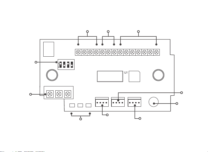
PCB FEATURES
Status
Reader
Inputs
234 5 6 7
1
Indicator
Outputs
8
9
Zones
10
11 12 13 14
Address DIP
Switches
Door Relay
Terminal
NO
ON
1 2 3 4
C
NC
RED
RELAY
ON
Indicator
YEL
WIEGAND
READ LED
LEDs
LC ASREDWHT GRN BLK Z1 Z2 Z3 Z4+ Z4–RA GND GND
GRN
DATA
XMT LED
PROG
RED
KYPD IN
Programming
RED
Keypad
Header
KYPD OUT
Piezo
+ –
RED
To Other
Keypad Bus
or AX‑Bus
To Panel
Keypad Bus
or AX‑Bus
Piezo
Figure 1: PCB Features
Digital Monitoring Products, Inc. | 734B Installation and Programming Guide 3
Page 8
INSTALL THE 734B
Mount the 734B
1
The module comes in a high‑impact plastic housing that you can mount directly to a
wall, backboard, or other flat surface.
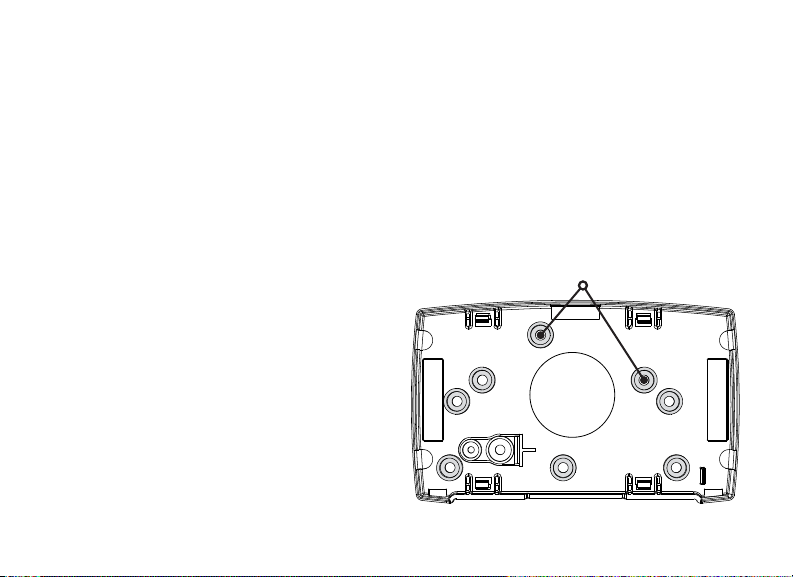
For easy installation, the back and ends of the 734B housing have wire entrances. The
back also contains multiple mounting holes that allow you to mount the module on
a single‑gang switch box. DMP recommends mounting the 734B near the protected
door. Refer to Figure 2for mounting hole locations on the housing base.
1. Remove the PCB from the
plastic housing by loosening
the clips on one side and gently
lifting it out of the housing base.
2. Insert the included screws in the
desired mounting hole locations
and tighten them to secure the
housing to the surface.
3. Reinstall the PCB in the housing
base.
Figure 2: Mounting Hole Locations
4 734B Installation and Programming Guide | Digital Monitoring Products, Inc.
Mounting Holes
Page 9
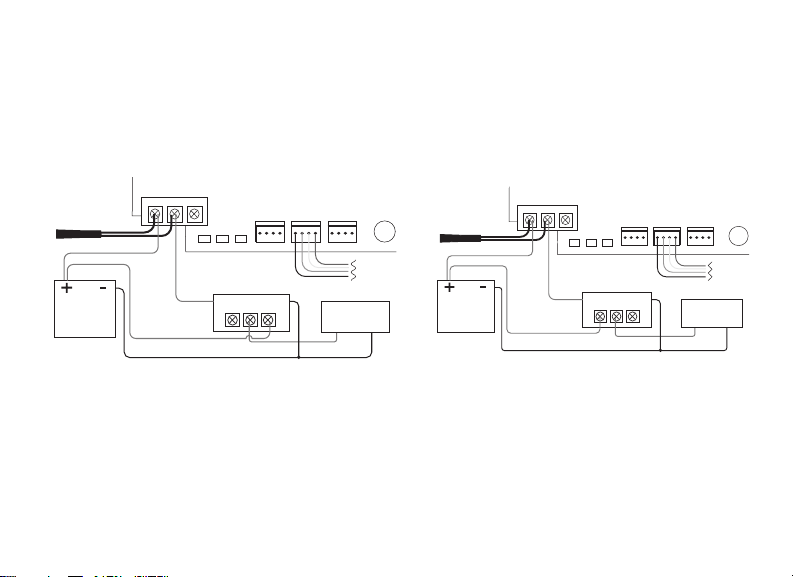
Wire the Access Control Lock
power supply negative
2
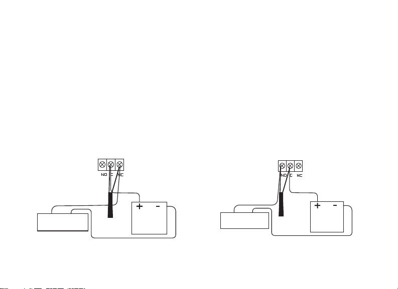
The 734B provides a Form C (SPDT) relay for controlling locks and other
electronically‑controlled barriers. The three relay terminals marked NO C NC allow
you to connect the device wiring to the relay for module control.
Use an additional power supply to power magnetic locks and door strikes. See
Figure 3and Figure 4for typical magnetic lock and door strike wiring.
The Form C relay draws up to 35mA of current and contacts are rated for 10Amps
(resistive) at 12/24VDC. When connecting multiple locks to the Form C relay, the
total current for all locks cannot exceed 10Amps. If the total current for all locks
exceeds 10Amps, problems may arise and an isolation relay may be needed. Refer
to “Isolation Relay (optional)” for more information.
734
Normally Closed
734
Normally Open
Power supply positive
Mag lock positive
to 734 terminal NC
–+
Magnetic Door
Lock
Model 333
Suppressor
Mag lock negative to
Figure 3: Typical Magnetic Lock Wiring
Digital Monitoring Products, Inc. | 734B Installation and Programming Guide 5
to 734 terminal C
12/24 VDC
Power Supply
Door strike positive
to 734 terminal NO
–+
DC Door Strike
Model 333
Suppressor
Door strike negative to
power supply negative
Figure 4: Typical Door Strike Wiring
Power supply positive
to 734 terminal C
12/24 VDC
Power Supply
Page 10

KYPD IN / KYPD OUT Connections
• KYPD IN (Keypad In): Receives and transmits data to the panel Keypad
bus/AX‑Bus.
• KYPD OUT (Keypad Out): Receives and transmits data out to other keypad(s) or
module(s). Install a dual‑connector harness to allow connection to other devices
up to the maximum number of devices supported.
When the 734B is powered from 24VDC, do not connect devices to KYPD OUT header.
Status LEDs
The 734B board contains three status LEDs.
• The Red LED turns on for the same duration as the door strike relay.
• The Yellow LED turns on for one second to indicate receipt of a valid input
determined by card format programming.
• The Green LED indicates data sent to the panel.
6 734B Installation and Programming Guide | Digital Monitoring Products, Inc.
Page 11
Isolation Relay (optional)
3
The Form C relay can control a device that draws less than 10Amps of current. If a
device draws more than 10Amps of current, or the sum of all devices controlled by
the Form C relay exceeds 10Amps, an isolation relay must be used. Refer to Figure 5
and Figure 6for isolation relay wiring.
734
Series
DATA
PROG
XMT LED
Isolation Relay
NO C NC
–+
RED
Module
KYPD IN
RED
KYPD OUT
Magnetic Lock
Mag Lock
+
–
RED
To Panel
Keypad
Bus
–+
Model 333
PIEZO
+
Suppressor
–
Normally Open
12/24VDC
Power
Supply
NO C NC
+
+
–
+
Common
Normally Open
Figure 6: Door Strike with an Isolation
Model 333
Suppressor
12/24VDC
Power
Supply
Normally Open
NO C NC
+
Normally Closed
+
–
+
Common
RED
YEL GRN
WIEGAND
RELAY
READ LED
ON
Magnetic Lock
Figure 5: Magnetic Lock with an Isolation
Relay
Digital Monitoring Products, Inc. | 734B Installation and Programming Guide 7
RED
YEL GRN
WIEGAND
RELAY
READ LED
ON
Isolation Relay
Magnetic Lock
NO C NC
Relay
734
Series
Module
PIEZO
RED
RED
KYPD OUT
Magnetic Lock
DC Door Strike
+
–
To Panel
Keypad
Bus
–+
+
RED
DATA
KYPD IN
PROG
XMT LED
–+
–
Page 12
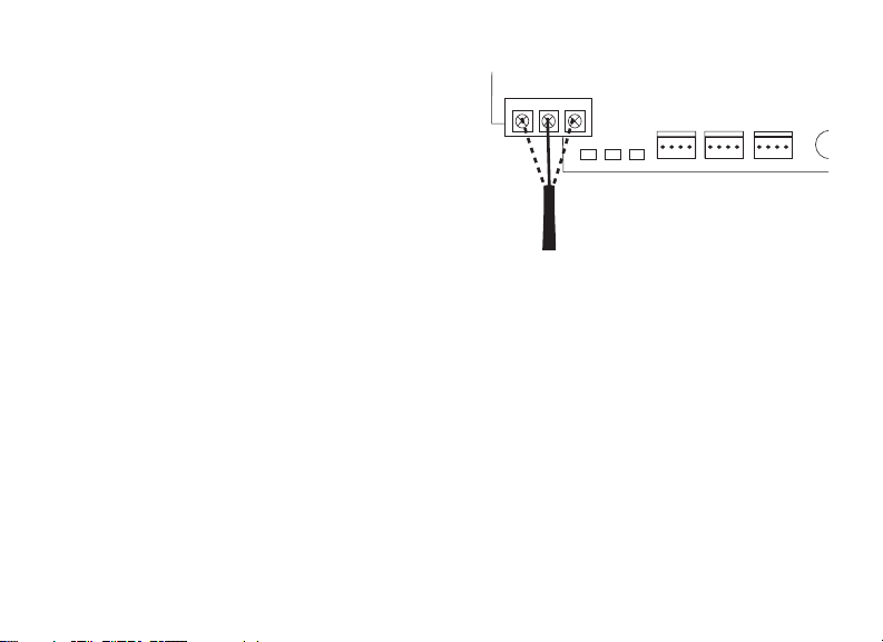
Install the 333Suppressor
PIEZO
–
4
Use the included 333suppressor
with the 734B to suppress any surges
caused by energizing a magnetic lock
or door strike.
Install the 333across the module’s
C(common) and NO (normally open)
or NC (normally closed) terminals.
Model 333
Suppressor
NO CNC
RED
WIEGAND
RELAY
READ LED
ON
YEL GRN
XMT LED
734
Series
Module
RED
KYPD OUT
RED
RED
DATA
PROG
KYPD IN
If the device being controlled by the
relay is connected to the NO and C
terminals, install the suppressor on the
Figure 7: 333Suppressor
Installation on the 734B
NO and C terminals.
Conversely, if the device is connected
to the NC and C terminals, install
the333Suppressor on NC and C
terminals.
The suppressor wire is non‑polarized.
Install the suppressor as shown in
Figure 7.
8 734B Installation and Programming Guide | Digital Monitoring Products, Inc.
+
Page 13

Wire the Zone Terminals
5
Terminals 8through 12connect grounded zones1through 3. Zones 2and 3can
also be used for access control with zone2providing a bypass feature and
zone3providing request to exit functionality.
Use the supplied 311 1k Ohm End‑of‑Line (EOL) resistors on each zone. Refer to the
panel programming guide for programming instructions. See Table 1and Figure 8for
more information on wiring the zone terminals.
Digital Monitoring Products, Inc. | 734B Installation and Programming Guide 9
Page 14

Zone # Recommended Device
1 Any burglary device
2 Door contact
3 REX (PIR or Button)
4 Any Device
Table 1: 734B Zone Uses
Zone 1
Zone 2
Zone 3
Zone 4
10
8
2
1
4 5 6 7
3
LC ASRED WHTGRN BLK Z1 Z2 Z3 Z4+ Z4–RA GND GND
9
11 12 13 14
1k Ω EOL
1k Ω EOL
1k Ω EOL
1k Ω EOL
Zone 3can also
be wired normally
closed with an
in‑line 1k Ohm
resistor
Figure 8: 734B Zone Terminal Wiring
10 734B Installation and Programming Guide | Digital Monitoring Products, Inc.
Page 15

Connect a Magstripe Reader
6
The 734B is compatible with ABA Track 2 Clock‑and‑Data magnetic stripe readers.
The module provides direct 12/24VDC, 200mA output to the reader on the RED
terminal connection. Figure 9shows a reader with wire colors RED, WHT, GRN, and
BLK connecting to terminals 1, 2, 3, and 4.
The green wire is Data and the white wire is Clock. The red wire connects 12/24VDC,
200mA maximum power and the black wire is ground.
The wire colors may be dierent depending on the reader being installed. Refer to
the literature provided with the reader for wire coding, wire distance, cable type
(such as shielded), and other specifications.
Magstripe Reader LED Operation
To provide visual indication of a valid card read, the magstripe reader can be wired
to illuminate the green LED for the duration of the door strike.
Connect the orange or brown wire to LC terminal5to have the green LED stay on
for the duration of the relay activation.
Magstripe Reader Annunciation
Connect the yellow wire to RA terminal6to have the remote annunciator turn on
anytime the panel instructs the 734B onboard piezo to turn on.
Digital Monitoring Products, Inc. | 734B Installation and Programming Guide 11
Page 16

Status Indicator Outputs
Terminals 5, 6, and 7provide connections for Remote LED Control, Remote Annunciation,
and Armed Status indicators.
LC (Remote LED Control)
Remote LED Control provides an unsupervised switched ground for a visual indicator
that turns on when the relay activates. Connect the wire from the LC Terminal to an
LED. The LED turns on for the duration the door strike relay is on. HID readers optionally
provide a connection for LED reader control.
LC Wire Color LED Color
Orange Green
Brown Red
RA (Remote Annunciation)
Remote Annunciation provides an unsupervised switched ground for a remote
annunciator that turns on when the Zone 2Bypass timer expires. Connect the wire from
the RA Terminal to a remote annunciator. The remote annunciator silences when the RA
restores. The remote annunciator (RA) switched ground operates even if the speaker is
programmed not to operate.
AS (Armed Status)
Armed Status provides an unsupervised switched ground for a visual or audible armed
status indicator that turns on when the burglary areas are armed, such as SYSTEM ON or
ALL SYSTEM ON. Connect a wire from the AS Terminal to an armed status indicator.
12 734B Installation and Programming Guide | Digital Monitoring Products, Inc.
Page 17

Caution: Status indicator outputs support a maximum of 100mA per terminal.
Exceeding the maximum rating on LC, RA, or AS terminals can damage equipment.
ABA Track 2
Clock-and-Data
Magstripe Reader
Yellow
Orange or Brown
Black (GND)
Green (Data 0)
White (Clock 1)
Red (12/24VDC)
10
8
9
11 12 13 14
ON
1 2 3 4
234 5 6 7
1
J3
LC ASRED WHT GRN BLK Z1 Z2 Z3 Z4+ Z4–RA GND GND
Figure 9: Magstripe Reader Wiring
Digital Monitoring Products, Inc. | 734B Installation and Programming Guide 13
Page 18

Set the 734B Address
7
To set the 734B address, move the DIP switches on the PCB to the appropriate
positions. See the following sections, Figure 10 and Table 2to determine how to set
Keypad Bus or AX‑Bus addresses.
If the 734B is the only device programmed into the panel, set it to address 2 or
higher.
Keypad Bus Addresses Explained
Each Keypad Bus address can accommodate one door output and four expansion
zones. A 734B with an address of 2on the Keypad Bus would represent door2and
zones21‑24. A 734B with a keypad address of 14would represent door14and
zones141‑144.
AX‑Bus Addresses Explained
XR550panels are capable of access control expansion using any of the five
AX/LX‑Bus headers (AX/LX500, 600, 700, 800, and 900). An AX‑Bus address
can accommodate one door output and one expansion zone. Because the 734B
has a built‑in four‑zone expander, three extra zones will be mapped to the 734B
automatically.
A 734B with an address of 1on AX500would represent door501and
zones501‑504. A 734B with an address of 2on AX500would represent
door505and zones505‑508. A 734B with an address of1 on AX700would
represent door 701 and zones701‑704.
14 734B Installation and Programming Guide | Digital Monitoring Products, Inc.
Page 19

Note: Hardwired zone expanders and modules do not communicate on an AX‑Bus.
Doors connected to the AX‑Bus do not have programmable device or
communication types and do not have assignable display areas.
ON
ON
ON
ON
1 2 3 4
1 2 3 4
ON
1 2 3 4
ON
1 2 3 4
ON
1 2 3 4
ON
5 6 7 8
1 2 3 4
ON
1 2 3 4
ON
1 2 3 4
ON
1 2 3 4
ON
9 10 11 12
1 2 3 4
ON
1 2 3 4
ON
1 2 3 4
ON
1 2 3 4
ON
13 14 15 16
1 2 3 4
1 2 3 4
Figure 10: Keypad/AX Bus Addresses
Digital Monitoring Products, Inc. | 734B Installation and Programming Guide 15
1 2 3 4
1 2 3 4
Page 20

734B Address Table
To set the module’s address, move the DIP switches to the appropriate positions. Refer
to Figure 10for Keypad Bus and AX‑Bus DIP switch positions.
Keypad Bus AX‑Bus
DEVICE/
DOOR
1 11‑14 501 501‑504 601 601‑604 701 701‑704 801 801‑804 901 901‑904
2 21‑24 505 505‑508 605 605‑608 705 705‑708 805 805‑808 905 905‑908
3 31‑34 509 509‑512 609 609‑612 709 709‑712 809 809‑812 909 909‑912
4 41‑44 513 513‑516 613 613‑616 713 713‑716 813 813‑816 913 913‑916
5 51‑54 517 517‑520 61 7 617‑620 717 717‑720 817 817‑820 917 917‑920
6 61‑64 521 521‑524 621 621‑624 721 721‑724 821 821‑824 921 921‑924
7 71 ‑74 525 525‑528 625 625‑628 725 725‑728 825 825‑828 925 925‑928
8 81‑84 529 529‑532 629 629‑632 729 729‑732 829 829‑832 929 929‑932
9 91‑94 533 533‑536 63 3 633‑636 733 733‑736 833 833‑836 933 933‑936
10 101‑104 537 537‑540 637 637‑640 737 7 37‑74 0 8 37 837‑840 937 937‑940
11 111‑114 541 541‑544 641 641‑644 741 741 ‑744 841 841‑844 941 941‑944
12 121‑124 545 545‑548 645 645‑648 745 745‑748 845 845‑848 945 945‑948
13 131‑134 5 49 549‑552 649 649‑652 74 9 749‑752 849 849‑852 949 949‑952
14 141‑144 553 553‑556 653 653‑656 753 753‑756 853 853‑856 953 953‑956
15 151‑154 557 557‑560 657 657‑660 757 757‑760 857 857‑860 957 957‑960
16 161‑164 561 561‑564 661 661‑664 761 761‑764 861 861‑864 961 961‑964
ZONES
DEVICE/
DOOR
ZONES
DEVICE/
DOOR
ZONES
DEVICE/
DOOR
ZONES
DEVICE/
DOOR
ZONES
DEVICE/
DOOR
ZONES
Table 2: Device Addresses and 734B Zone Numbers
16 734B Installation and Programming Guide | Digital Monitoring Products, Inc.
Page 21

PROGRAM THE PANEL
To access the Programmer menu, reset the panel, enter 6653 (PROG), then press CMD.
After completing each of the following steps, press CMD to advance to the next option.
Refer to the panel programming guide as needed.
DEVICE SETUP
DEVICE SETUP
DEVICE NO: ‑
DEVICE SETUP
*UNUSED*
Digital Monitoring Products, Inc. | 734B Installation and Programming Guide 17
DEVICE SETUP
Advance to DEVICE SETUP, then press any select area or top
row key to enter the setup menu.
Device Number
Set the module’s address. For information about valid
addresses, refer to Table 2.
Device Name
Press any select area or top row key, then enter a name for
the module.
Page 22

DEVICE SETUP
TYPE: DOOR
DEVICE SETUP
COMM TYPE: AX‑BUS
Configure additional options as needed. To configure specific options for the module
locally, do not program CARD OPTIONS or 734 OPTIONS in Device Setup.
18 734B Installation and Programming Guide | Digital Monitoring Products, Inc.
Device Type
Press any select area or top row key, then select DOOR as
the device type.
Communication Type
If the module is connected to the Keypad Bus, select KPD
(Keypad Bus). If the module is connected to the AX‑Bus,
select AX‑BUS. Press any select area or top row key to
display available options.
Page 23

PROGRAM THE 734B
When you program a 734B, you can use a keypad connected to the 734B programming
header and set to address 1. For 12V applications, connect the keypad to the module
using a Model 330 4‑wire harness. For 24V applications, connect the keypad to the
module using a Model 330‑24 4‑wire programming harness with in‑line resistor.
Caution: Do not connect a keypad using a standard Model 330harness if using a
24V power supply! Damage to the keypad could occur.
You can also program the 734B from an XR150/XR550Series panel. If you choose to
program the 734B from the panel, all future programming should be performed through
the panel. The panel’s programming overrides any programming performed from a
keypad connected to the 734B. While the 734B is in programming mode, it will not be
able to communicate with the panel.
You can complete the following programming steps with Dealer Admin, Entré, locally
from a keypad connected to the 734B, or from the panel.
Note: If you program BINs from the panel or Dealer Admin, formats used by the
module will be subtracted from the total number of available formats for all
connected 734B modules. BINs longer than 6digits cannot be programmed from
Dealer Admin.
Digital Monitoring Products, Inc. | 734B Installation and Programming Guide 19
Page 24

There are three methods to program Bank Identification Number (BIN) codes. The
first method allows you to program BINs as user codes and process them at the panel,
allowing up to 10,000 BINs. The second method allows you to program BINs as user
codes and process them locally, allowing up to 64 BINs. The third method allows you to
program the 734B as a standalone access control module and allows up to 64 BINs. For
more information about programming options, refer to “Programming Reference.”
Program BINs as User Codes (Process at Panel)
Processes BINs at the panel. Allows up to 10,000 BIN codes. This method also allows you
to use schedules, run reports, make users inactive, and use Virtual Keypad Access.
1. At ENABLE LOCAL PROCESSING, select NO.
2. At NO COMM WITH PNL, select any option.
3. Program BINs as user codes at the panel. All BIN codes are processed at the
panel and saved in panel programming as user codes.
20 734B Installation and Programming Guide | Digital Monitoring Products, Inc.
Page 25

Program BINs Locally (Process Locally)
Processes the BINs at the module. Allows up to 64 BIN codes. This method also allows
you to use schedules, run reports, make users inactive, and use Virtual Keypad Access.
1. At ENABLE LOCAL PROCESSING, select YES.
2. At NO COMM WITH PNL, select OFF, ANY, ON, or LAST.
3. Program BINs in the 734B. All BIN codes are processed locally.
4. Program the 734B serial number as a user code in the panel. The 734B processes
all valid access locally and sends the serial number to the panel as a user code.
Program the Module in Standalone Mode
Processes BINs at the module. Allows up to 64 BIN codes. This method also allows you
to use the 734B as a standalone access control system without requiring a panel.
1. At ENABLE LOCAL PROCESSING, select YES.
2. At BIN CODE x, press a top row select key and enter the BIN code.
3. At NO COMM WITH PNL, select BIN. All BIN codes are processed and saved
locally in module programming.
Digital Monitoring Products, Inc. | 734B Installation and Programming Guide 21
Page 26

PROGRAMMING REFERENCE
734B PROGRAMMING
VER VVV MM/DD/YY
SERIAL #: 123456
INITIALIZE ALL?
NO YES
ARE YOU SURE?
YES NO
22 734B Installation and Programming Guide | Digital Monitoring Products, Inc.
PROGRAMMER MENU
When you connect the keypad to the 734B module, the
version number and release date display. Press CMD to enter
the Programming Menu.
SERIAL NUMBER
Enter the device serial number. Range is 100000 ‑ 999999.
Press CMD to advance to initialization question.
INITIALIZATION OPTION
These options can set the 734B module’s programming
memory back to factory defaults. Press any select key or area
to enter the Initialization Menu.
Initialize Confirm Option: After selecting YES to clear the
Access Options, the 734Bdisplays SURE? YES NO for
confirmation to clear the memory. This is a safeguard
against accidentally erasing the programming. No memory is
cleared from the programming until you answer YES to the
SURE? option. Selecting NO leaves communication options
unchanged.
Page 27

ACTIVATE ZONE2
BYPASS? NO YES
Digital Monitoring Products, Inc. | 734B Installation and Programming Guide 23
Activate Zone 2Bypass
Select YES to activate the zone2bypass operation. Selecting
NO allows standard zone operation on zone2. The default is
NO.
If the door being released by the 734B module is protected
(contact installed), a programmable bypass entry/exit timer
can be provided by connecting its contact wiring to module
zone2. When the onboard Form C relay activates and
the user opens the door connected to zone2, the zone is
delayed for the number of seconds programmed in ZONE
2BYPASS TIME allowing the user to enter/exit during an
armed period.
If zone2does not restore (door closed) within the
programmed time, the piezo sounds every other second
during the last ten seconds. If zone2restores prior to the
end of the programmed time, the piezo silences. If the
zone does not restore before the programmed time, the
734B ends the bypass and indicates the open or short zone
condition to the panel.
Page 28

ZONE2BYPASS
TIME: 40
Zone 2 Bypass Time
Enter the number of seconds to elapse before the bypass
timer expires. The range is 20‑250seconds. Press any select
key or area to enter the number of seconds. The default is
40seconds. Figure 11shows how the bypass option works.
40
10 seconds before
the bypass time expires,
the device beeps if
the door is still open.
A zone open/short is
End of
indicated if the door
Timer
remains open.
5-Second
Strike
40-Second Zone 2
Bypass Entry/Exit Timer
Seconds
Figure 11: Zone 2Bypass Timeline
RELOCK ON ZONE2
CHANGE? NO YES
Relock on Zone 2Change
Selecting YES turns the relay o when zone2 changes state.
Selecting NO leaves the relay on when zone2 changes
state. Turning o the relay allows a long strike time to be
automatically ended upon zone 2change and relocks the
door. The default is NO.
Note: If using the 734B as a standalone access control
unit not connected to a panel, set RELOCK ON ZONE
2CHANGE to NO.
24 734B Installation and Programming Guide | Digital Monitoring Products, Inc.
Page 29

ACTIVATE ZONE3
REX? NO YES
Digital Monitoring Products, Inc. | 734B Installation and Programming Guide 25
Activate Zone 3Request to Exit
Selecting YES activates the zone3Request to Exit (REX)
option. Selecting NO allows standard zone operation on
zone3. Default setting is NO.
Connect a motion sensing device or a mechanical switch to
zone3to provide REX capability to the system. Zone 3can
be used to activate the strike relay and bypass or activate
bypass only. For zone wiring details, refer to Figure 8.
Activate Strike Relay and Bypass
Wire zone 3as normally open with a 1k Ohm EOL resistor.
When zone3shorts, the onboard Form C relay activates for
the programmed number of seconds. See “Zone 3REX Strike
Time”. During this time, the user can open the protected
door to start the programmed zone2bypass entry/exit timer.
After the programmed number of seconds, the relay restores
the door to its locked state.
Activate Bypass Only
Wire zone 3as normally closed with an in‑line 1k Ohm
resistor.
When zone3 opens from a normal state, only a bypass
occurs and the onboard relay does not activate.
Page 30

ZN 3REX STRIKE
TIME: 5
ACTIVATE ONBOARD
SPEAKER? NO YES
BIN CODE LENGTH
6
LOCAL PROCESSING
ENABLE? NO YES
BIN CODE 1
123456
26 734B Installation and Programming Guide | Digital Monitoring Products, Inc.
Zone 3REX Strike Time
Enter the number of REX seconds to elapse. The range
is5to 250seconds. Press any select key or area to enter the
number of seconds. The default is 5seconds.
Activate Onboard Speaker
Select YES to enable the onboard piezo for local
annunciation, such as alarm and trouble annunciations. Select
NO to turn the speaker o for all operations. This does not
aect remote annunciator open collector (RA) operation. The
default is NO.
BIN Code Length
Enter the length of the BIN code. Range is 1 ‑ 8. The default
BIN code length is 6.
Enable Local Processing
To enable local programming, select YES. To advance to NO
COMM WITH PNL, select NO. Default is NO.
BIN Code
Program up to 64 consecutive BIN codes according to the
length chosen in BIN CODE LENGTH. Press CMD, enter the
BIN code, then press CMD again. To advance to the next
prompt, leave the BIN code blank and press CMD.
Page 31

NO COMM WITH PNL
OFF
OFF BIN ANY ON
OFF BIN ANY ON
OFF BIN ANY ON
OFF BIN ANY ON
LAST
Digital Monitoring Products, Inc. | 734B Installation and Programming Guide 27
No Communication with Panel
Define the relay action when communication with the panel
has not occurred for 5seconds. Default is OFF. Press any
select key or area to change the default relay action:
Press the first select key or area to choose OFF (Relay
Always O). The relay does not turn on when a BIN code
is received. OFF does not aect any REX operation. If
communication is lost during a door strike, the relay remains
on for the door strike duration but turns o at the end of the
door strike timer.
Press the second select key or area to choose BIN (Accept
BIN Code). Door access is granted when the received BIN
code matches any programmed BIN code.
Press the third select key or area to choose ANY (Any
BIN Code Read). Access is granted when any BIN code is
received.
Press the fourth select key or area to choose ON (Relay
Always On). The relay is always on. Press CMD to display the
next action.
Press the first select key or area to choose LAST (Keep Last
State). The relay remains in the same state and does not
change when communication is lost.
Page 32

REMOVE KEYPAD
28 734B Installation and Programming Guide | Digital Monitoring Products, Inc.
REMOVE KEYPAD
After programming is saved, the REMOVE KEYPAD option
continually displays with no timeout if the keypad remains
connected to the module. After five seconds, the piezo
begins sounding continually. To disconnect the keypad and
silence the piezo, remove the keypad harness.
Page 33

KEYPAD BUS WIRING SPECIFICATIONS
• DMP recommends using 18or 22‑gauge unshielded wire for all keypad
and AX‑Bus/LX‑Bus circuits. Do not use twisted pair or shielded wire for
AX‑Bus/LX‑Bus and Keypad Bus data circuits. All 22‑gauge wire must be
connected to a power‑limited circuit and jacket wrapped.
• On Keypad Bus circuits, to maintain auxiliary power integrity when using
22‑gauge wire do not exceed 500ft. When using 18‑gauge wire do not exceed
1,000ft. To increase the wire length or to add devices, install an additional power
supply that is listed for Fire Protective Signaling, power limited, and regulated
(12/24VDC nominal) with battery backup.
Note: Each panel allows a specific number of supervised keypads. Add
additional keypads in the unsupervised mode.
• Maximum distance for any one bus circuit (length of wire) is 2,500ft regardless
of the wire gauge. This distance can be in the form of one long wire run or
multiple branches with all wiring totaling no more than 2,500ft. As wire distance
from the panel increases, DC voltage on the wire decreases. Maximum number of
AX‑Bus/LX‑Bus devices per 2,500ft circuit is 40.
• Maximum voltage drop between the panel (or auxiliary power supply) and any
device is 2VDC. If the voltage at any device is less than the required level, add
an auxiliary power supply at the end of the circuit. When voltage is too low, the
devices cannot operate properly.
For additional information refer to the panel’s Installation Guide or the 710Installation
Sheet (LT‑0310).
Digital Monitoring Products, Inc. | 734B Installation and Programming Guide 29
Page 34

PRODUCT SPECIFICATIONS
Primary Power 8.5VDC to 28.5VDC
Current Draw
Standby 240mA (Includes 200mA for magstripe reader)
Alarm 260mA (Includes 200mA for magstripe reader)
Form C Relay 35mA at 12/24VDC
Zones 5VDC, 2mA max
Dimensions 4.5W x 2.75H x 1.75Din
11.43W x 7H x 4.45Dcm
Weight 5.6oz 0.16kg
30 734B Installation and Programming Guide | Digital Monitoring Products, Inc.
Page 35

COMPATIBILITY
XR150/XR550 Series Panels
Readers
The 734B Access Control module has been tested with various magnetic stripe card
readers. To be compatible, magstripe readers must use Clock‑and‑Data output in ABA
Track 2 format. Verify all reader wiring with reader manufacturer to ensure proper
operation.
Digital Monitoring Products, Inc. | 734B Installation and Programming Guide 31
Page 36

Page 37

Page 38

Page 39

Page 40

LT-1952 21112 © 2021 Digital Monitoring Products, Inc.
 Loading...