

Page 1
INSTALLATION 521LX and LXT Addressable Smoke Detectors
Description
The Model 521LX and 521LXT Smoke Detectors are the
industry’s finest smoke detectors with analog features such
as remote maintenance reporting (CleanMe™), drift
compensation, and multi-criteria detection. These smoke
detectors incorporate an addressable single point module
for connection to the LX-Bus™ of an XR200 Command
Processor™ Panel with firmware version 1.04 (6/11/98) or
higher. The 521LXT also includes multi-criteria fast response
heat sensor algorithms for detection of a broad range of
fires.
Single Point Addressable
The 521 incorporates a factory mounted, addressable
single point zone expander on the back of the smoke
detector. The included 4-wire harness allows a direct
connection to the LX-Bus of an XR200 panel . The integrated
zone expander reports smoke detector alarm and service
conditions to the panel as a single zone. Also included is a
TXD LED that flashes when data is sent to the XR200
panel.
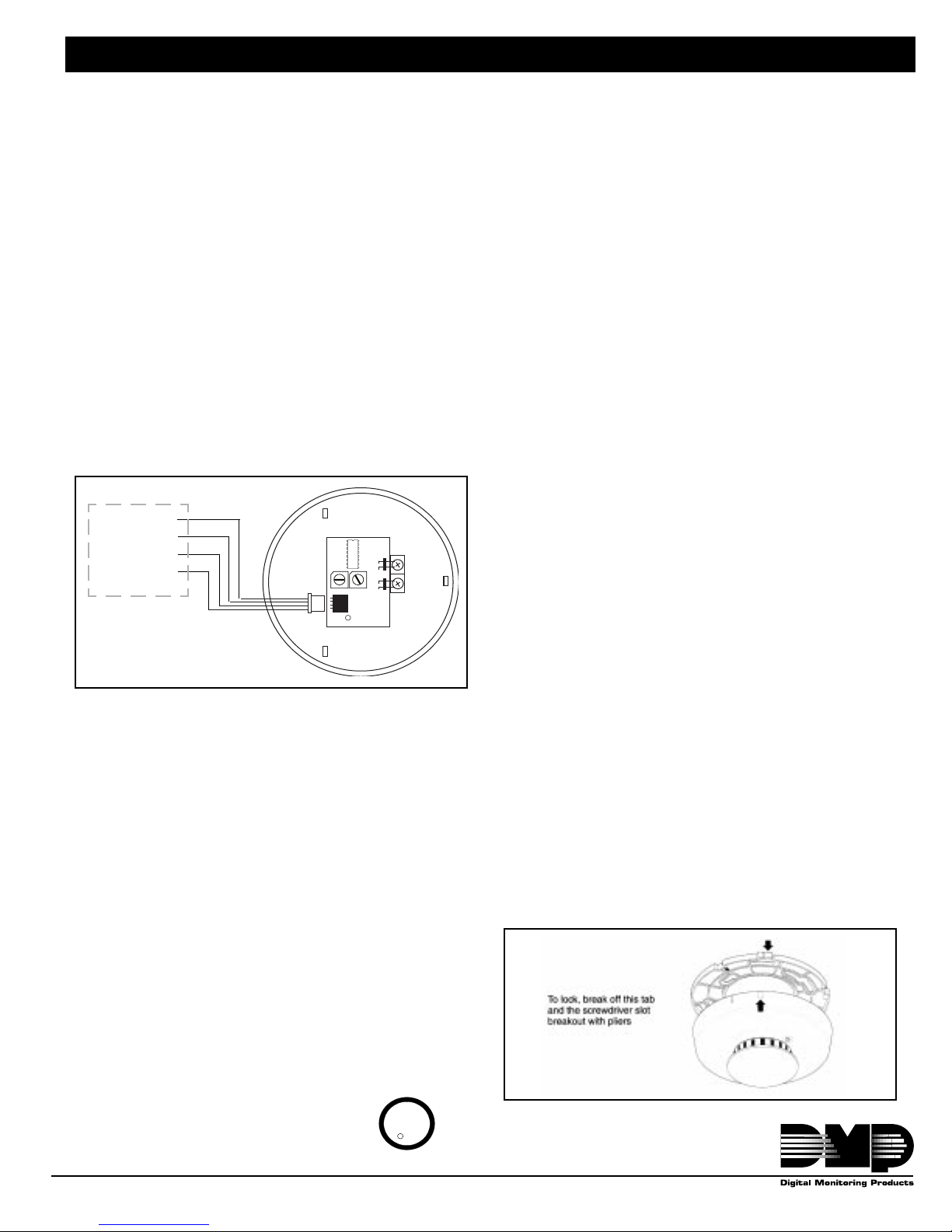
Figure 1
Black (common)
Green (data)
0
0
1
1
9
9
2
2
8
8
3
3
7
7
4
4
6
6
5
5
onestens
J1
Bottom view
J7
J4
Yellow (data)
Red (Smoke
power)
XR200 LX-Bus
Requires Model 462N,
462P, 472, or 481
Interface Cards.
TXD
521 Power and Data Bus Wiring
CleanMe™ Remote Maintenance/Trouble
Reporting Feature
The 521 detectors have a unique feature that allows a
service signal to be sent to the XR200 when the smoke
detector has drifted outside UL sensitivity ranges or a
hardware fault exists. In most cases, the signal will be the
result of the detector becoming dirty over time and, as a
result, are over sensitive. This condition could result in a
false alarm. The CleanMe™ signal enables the XR200 to
receive a service signal allowing an installer time to clean
the detector by replacing the inexpensive optical chamber
with a new one (DMP Model 525). This service information
can be transmitted to the Central Station.
Self-Diagnostics with Automatic Sensitivity
Testing
Each 521 photoelectric smoke detector monitors its own
sensitivity and operational status. Once a day, and
immediately upon first power up, it performs a full diagnostic
test that includes a dynamic test of the sensing chamber
and internal electronics. If the detector drifts out of its
sensitivity range or fails internal diagnostics, the alarm LED
flashes once every second to indicate trouble. This meets
NFPA 72 field sensitivity testing requirements without the
need for external meters.
Drift Compensation Built-In
The 521 detector is the industry’s first addressable smoke
detector with built-in drift compensation. The 521
automatically adjusts sensitivity, up to a maximum of 1.0%/
ft., as it becomes dirty. This feature increases immunity to
dust and dirt by 30-50%.
Installation
Consult Local Authority Having Jurisdiction (AHJ) and
NFPA 72 for specific installation information regarding
smoke detector spacing, placement, and special
applications.
The 521 detectors wire directly to the XR200 panel 4-wire
LX-Bus™. See Compatible LX-Bus Interface Cards. When
wired to the panel LX-Bus, the 521 uses only one of the
available expansion zone numbers allowing you to assign
additional zone expanders to the next zone number address.
See Addressing the 521LX and LXT.
Consider the Locking Mechanism BEFORE
Installation
Each 521 detector head is equipped with a break away
locking tab slot to prevent unauthorized removal of the
detector head . For installations where unauthorized removal
of the detector head is not a concern, i.e. high ceilings, no
action is required. The head can be removed by simply
turning counterclockwise.
However, when the head must lock to the base, simply
break away the locking tab and the “knock out” for the
screwdriver slot with a pair of pliers. Then, to remove the
detector head, insert a small screwdriver into the slot of the
side of the base and press in while simultaneously turning
the detector head counterclockwise (see Figure 2).
Figure 2
CleanMe™ is a trademark of Sentrol, Inc.
2841 E. Industrial Drive Springfield, MO 65802-6310 800-641-4282
U
R
L
LISTED
LT-0403 (7/98)
Page 2
Installing the Mounting Base
The mounting base included with each 521 makes the
smoke detector easy to install and remove if necessary.
The detector head simply twists off of its 4.75" mounting
base.
The mounting base connects directly to standard singlegang electrical boxes, three-inch round, or four-inch
octagonal boxes. The base may also be mounted without
electrical boxes if approved by the AHJ or if codes allow.
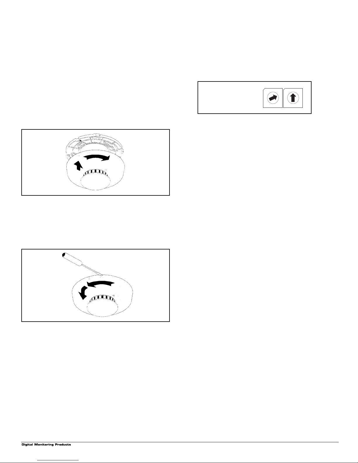
Installing the Detector Head to Mounting Base
To install a detector head, simply line up the raised marking
on the side of the detector with the arrow on the mounting
base. Insert the head and rotate it clockwise approximately
15 degrees to snap into place (see Figure 3).
Figure 3
Removing the Detector Head
To remove the detector head, simply turn counterclockwise.
However, if the locking tab slot has been removed, insert a
small screwdriver into the locking tab slot on the side of the
base and press in while simultaneously turning the detector
head counterclockwise (see Figure 4).
Figure 4
Wiring
First, pull wire through electrical box, then through center
opening of the 521 mounting base. Connect the 4-wire
harness to the J1 terminal according to the wiring diagram
in Figure 1.
Follow the wiring in Figure 1 when connecting the 521
detector to the XR200 LX-Bus. The maximum distance for
any one LX-Bus circuit is 2,500 feet. The maximum number
of LX-Bus devices on any one 2,500 foot circuit is 40. To
increase the wiring distance and/or number of devices, you
must install a DMP 710 Bus Splitter/Repeater Module.
Refer to page 4 for more information about the Model 710.
Addressing the 521LX and LXT
Addressing the 521 requires setting two on-board rotary
switches to match the address of the XR200 LX-Bus zone
number. For zone numbers 100 to 199, set the switches to
match the last two digits of the zone number. For example,
to assign the 521 detector to zone number 120, you would
set the left rotary switch (labeled "TENS") to 2 and the right
rotary switch (labeled "ONES") to 0.
Example:
Rotary switches on the
521 module set for zone
address 120.
0
9
8
7
6
TENS
5
0
2
3
9
8
7
6
5
ONES
1
2
3
4
1
4
Figure 5: Address switches
Testing Each Detector
All 521 smoke detectors are shipped with a plastic dust
cover for use in areas where construction is continuous.
Smoke detectors will not work with the dust cover in place.
Remove the dust cover when installation is completed,
prior to testing. Also, disconnect alarm notification
appliances, releasing service devices, and extinguishing
systems prior to detector tests. Be sure to reconnect all
devices at the conclusion of testing.
Per NFPA 72, “all smoke detectors shall be tested in place
annually, to ensure smoke entry into the sensing chamber
and alarm response. Testing with smoke or listed aerosol
acceptable to the manufacturer, shall be permitted.” Annual
functional testing is best accomplished using Smoke! In a
can, Model 526, available from DMP. Carefully follow the
directions on the can.
The detector performs a smoke test every 9 seconds while
flashing its LED. If smoke is detected, the rate of sampling
increases to every 4.5 seconds. Excessive smoke must be
detected in three consecutive tests for the alarm to sound.
Therefore, when testing the detector with smoldering punks
or cotton wicks, hold the smoke source near the opening for
smoke entry and gently direct smoke into the detector for 20
seconds or until an alarm is indicated.
PROPERLY EXTINGUISH THE SMOKE SOURCE AFTER
TESTING!
This is a gross, go/no-go test and is not a reliable indication
of detector sensitivity. If it is successful, the LED will remain
lit. For in-depth sensitivity testing, see Sensitivity Level
Test Mode below. Reset the detector, then blow or brush off
the optical block base and snap a new optical block
chamber (see Figure 8) back in place, replace the cap and
verify sensitivity with the Sensitivity Level Test.
BE SURE TO
521LX and LXT Installation
2
2841 E. Industrial Drive Springfield, MO 65802-6310 800-641-4282
Page 3

Additional Diagnostics Available with
Sensitivity Level Test Mode
Each smoke detector also includes a special sensitivity
level test mode that is activated by holding a magnet near
the integral reed switch for more than one second (see
Figure 6). Once the routine starts, the alarm LED will flash
one to nine times, indicating actual sensitivity and whether
or not service is required.
Figure 6
After the sequence of blinks, if the sensitivity is found to be
within limits and if all other tests pass, the detector will go
into alarm until reset by the panel. If the sensitivity is not
within limits, or an unserviceable hardware fault has been
detected, the alarm LED will continue to flash once per
second until the detector is reset by the panel. If sensitivity
test indicates an unacceptable level, take action
recommended above. See the 521 Sensitivity Table.
etamixorppA
noitarucsbOnoitarucsbO
noitarucsbOnoitarucsbO
noitarucsbO
).tf%().tf%(
).tf%().tf%(
).tf%(
otohP
53.42
58.33
06.34
01.35
06.26
01.27
58.18
53.19
sknilBnoitacidnInoitcA
1
tonsirotceteD
hguoneevitisnes
nihtiwsirotceteD
stimilytivitisnesstimilytivitisnes
stimilytivitisnesstimilytivitisnes
stimilytivitisnes
ootsirotceteD
evitisnes
Figure 7: 521 Sensitivity Table
Smoke Detector Dip Switches
If the 521 smoke detector includes dip switches to the left
of the screw terminals, they are factory preset and must not
be changed.
2841 E. Industrial Drive Springfield, MO 65802-6310 800-641-4282
Maintenance, Cleaning & Sensitivity
The 521 smoke detectors are designed for easy field
service and maintenance. If a smoke detector drifts beyond
its approved sensitivity range for more than 24 hours or fails
internal diagnostic tests during power-up, the unit
automatically indicates trouble by flashing its LED every
second. Under normal conditions the LED flashes every 9
seconds. Therefore, a simple visual check of the LED
status meets NFPA 72 field sensitivity testing requirements
without the need for external meters or ladders. In
accordance with NFPA 72-7-3.2.1, smoke detector
sensitivity should be checked within one year after
installation and every alternate year thereafter, in
commercial installations, or every three years in residential
sites.
Figure 8
Model 525
▲
The sensing chamber of the 521 photoelectric detector
ytivitisnesnur-erdnatinuteseR
ehtsniamernoitacidnifi,tset
.tinuecalper,emas
teseR.snoitcurtsnirepnaelC
,tsetytivitisnesnur-erdnatinu
.tinuecalper
enoN
.snoitcurtsni
,emasehtsniamernoitacidnifi
kcolblacitpoerusebotkcehC
nwoddeppanssirevoc
repnaelC.yletelpmoc
unsnaps for easy field cleaning and service. Whenever the
status LED indicates cleaning is necessary, remove the
photoelectric detector cap, snap off and throw away the
optical block. Then blow or brush off the optical block base
and snap a new optical block chamber (see Figure 8) back
in place, replace the cap and verify sensitivity with the
Sensitivity Level Test.
Compatible LX-Bus Interface Cards
The following Expansion Interface Cards are compatible
with the 521 smoke detectors: 462N, 462P, 472, and 481.
Specifications
egnargnitarepOCDV0.51-8.8
)kpotkp(elppirmumixaMV(%01
tnerrucgnitarepoybdnatSAm8.8
tnerrucgnitarepomralAAm82
cirtceleotohpytivitisneS%00.1-05.0+%1.3
erutarepmetgnitarepO23
egnarytidimuhgnitarepOgnisnednoc-noN%59ot0
ytinummIIFRzHM0001-0;muminimm/V02
roloCesabdnadaehetihW
)ylnoTXL(rosnestaeH531
:esirfoetaR51
emitpu-rewoPsdnoces51
tnemtsujdanoitasnepmoctfirD.xam.tf/%0.1
:snoisnemiddaehrotceteDretemaid"5thgieh"2
:snoisnemidgnitnuoMretemaid"57.4thgieh"3.
sgnitsiL862LU
)
p-p
o
o
o
o
001otF
F
F
o
501>dnanim/F
F
521LX and LXT Installation
3
Page 4

LX-Bus™ Installation Specifications
e
.
Three factors determine the performance characteristics of the DMP LX-Bus™: the
devices connected, and the
amount
of current required by the devices. The three specifications to keep in mind when
planning an LX-Bus installation are:
1. Maximum cumulative distance for any one LX-Bus circuit is 2,500 feet. This number can be increased to 50 if
the wire run remains under 2,000 feet.
2. Maximum number of LX-Bus devices per 2,500 feet is 40 regardless of the gauge of wire. This distance can be
in the form of one long wire run or multiple branches with all wiring totalling no more than 2,500 feet.
3. Maximum voltage drop between the panel (or auxiliary power supply) and any device connected to the LX-Bus
is rated at 2.0 VDC. As an example of the voltage drop, if the voltage across the red and black wires at the panel
is 13.8 VDC the voltage measured at each device on the circuit must be equal to or greater than 11.8 VDC.
If the voltage at any device, including a 710 module, is less than the required level, a UL listed auxiliary power supply
should be added at the end of the circuit. (The voltage drop can also be reduced by increasing the gauge of wire
used on the circuit.) The 2.0 VDC rule applies to LX-Bus circuits powered either by the panel or by an auxiliary power
supply.
length
of wire used, the
number
of
Voltage across red and
black here is 13.8 VDC
Voltage across red and black at all devices
along the LX-Bus must be 11.8 VDC or greater
Panel
LX-Bus Devices LX-Bus Devices
If the wiring distance between the two auxiliary power
Do not connect the Red wire between
the panel and the first device.
Voltage across red and
black here is 13.8 VDC
Panel
LX-Bus Devices
Voltage across red and black at all
devices along the LX-Bus must be
11.8 VDC or greater
▲
Power Supply
supplies is less than 250 feet, do not connect the Red
wire between the 710 and the first device.
LX-Bus Devices
710 Bus Module
A second power supply is only
required if the voltage drop from th
first supply is greater than 2.0 VDC
Power Supply
Multiple LX-Bus circuits
In this example, the first 710 module is in close proximity to the panel. At this point, the 710 is used to branch the LX-Bus
into three separate circuits. Each of these circuits can be run a distance of 2,500 feet. At the end of the 2,500 feet, another
710 module can be installed to add another 2,500 feet of LX-Bus capability.
Note: The total distance of all circuits cannot exceed 15,000 feet.
LX-Bus Devices
710 LX-Bus Module
Panel
Install the 710 module at the
point where the circuits divide.
2,500 feet
2,500 feet
2841 E. Industrial Drive Springfield, MO 65802-6310 800-641-4282
2,500 feet
2,500 feet
2,500 feet
2,500 feet
Digital Monitoring Products
710 Module
Specifications
Power: 8.0 to 15.0 VDC
Current: 30mA
Dimensions: 4.5"x2.75"x1.75"
Accepts 14 to 22 AWG Wire.
For more 710 information see
LT-0310.
 Loading...