

Page 1
1122 WIRELESS PIR MOTION DETECTOR
Installation Guide
PROGRAM THE PANEL
When programming the 1122 in the panel, refer to the panel
programming guide as needed.
Figure 1: 1122 Wireless PIR
Motion Detector
DESCRIPTION
The 1122 Wireless PIR Motion
Detector uses passive infrared
technology to detect motion in a
wide angle lens pattern.
The 1122 also features an internal
case tamper, survey LED, and low
battery indicator.
Pet immunity is available for animals
up to 55 pounds and can be turned
on or o. Disarm/disable, pulse
count, and adjustable sensitivy are
also oered on the 1122.
Compatibility
All DMP 1100 Series Wireless
Receivers and burglary panels.
1
2
1. In ZONE INFORMATION, enter the wireless ZONE number.
2. Enter the ZONE NAME.
3. Select NT (Night) as the ZONE TYPE.
4. Select the AREA.
5. At the NEXT ZONE prompt, select NO.
6. Select YES when WIRELESS? displays.
7. Enter the eight-digit SERIAL# and press CMD.
8. Enter the SUPRVSN TIME and press CMD.
9. Choose whether or not to enable DISARM DISABLE.
Note: Selecting YES allows the 1122 to be disabled for
Night and Exit type zones while the area is disarmed.
10. Choose either 2 or 4 for the PULSE COUNT.
Note: The pulse count is the number of pulse inputs
(trips) the 1122 needs to sense before going into alarm.
11. Choose either LOW or HIGH for the SENSITIVITY.
Note: Selecting LOW sensitivity may reduce false alarms
for installations in harsh environments.
12. Choose whether or not to enable PET IMMUNITY.
13. At the NEXT ZONE prompt, select YES if you are finished
programming the zone. Select NO if you would like to
access additional programming options.
INSTALL THE BATTERY
Use only a 3.0V lithium battery, DMP Model CR123A, or the
equivalent battery from a local retail outlet. Keep in mind, when
setting up a wireless system, program zones and connect the
receiver before installing batteries in the transmitters.
1. Remove the holding screw at the lower end of the 1122
case and gently lift o the cover.
2. Observing polarity, place the battery in the holder and
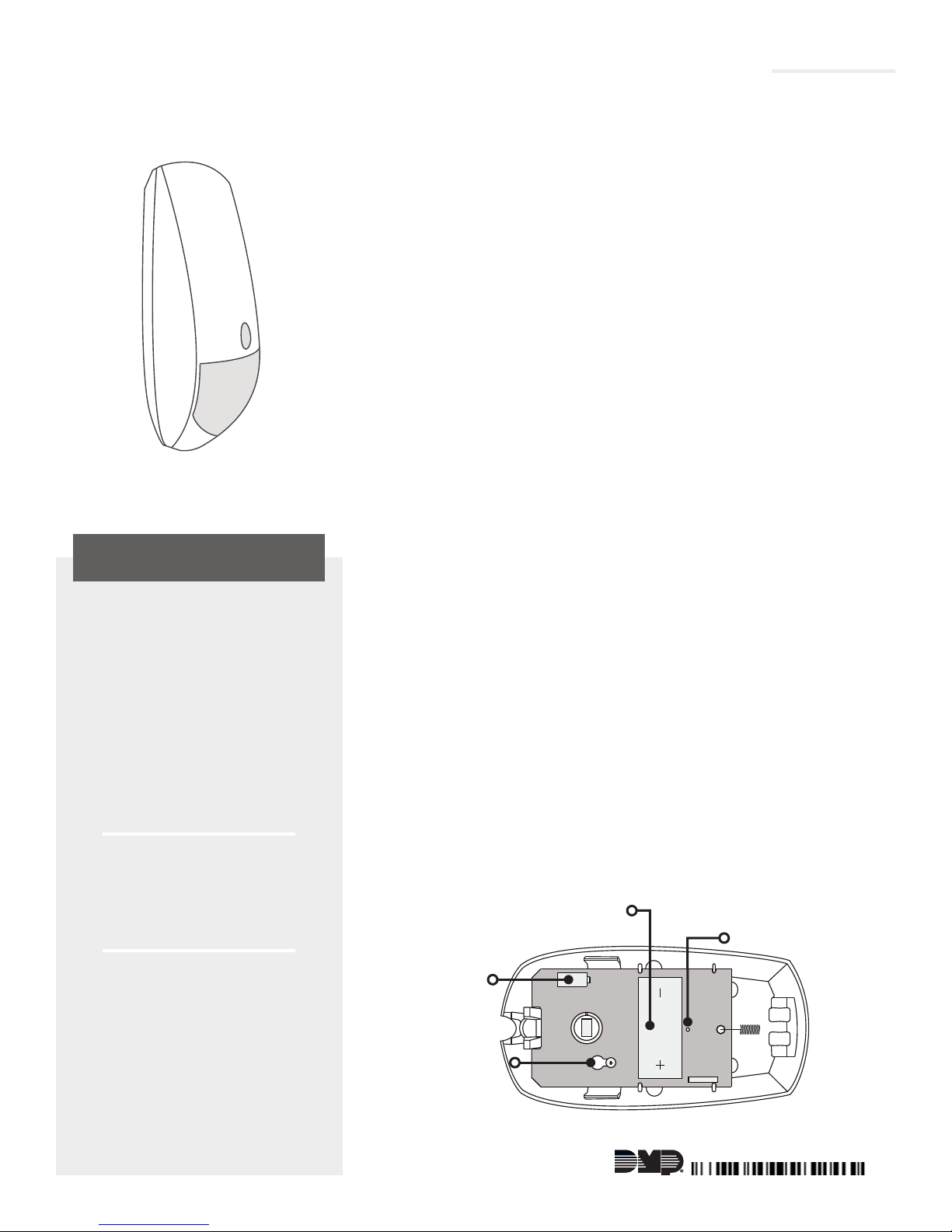
press into place. See Figure 2 for the battery location.
Battery
Location
Survey LED
What is Included?
• One 1122 Wireless
PIR Motion Detector
• One 3V lithium
CR123A battery
Tamper
Switch
PCB
Screw
Figure 2: 1122 Housing and PCB
LT-1647 © 2017 Digital Monitoring Products, Inc.
17164
Page 2

3
SELECT A LOCATION
The 1122 provides a survey capability to allow one person to confirm communication with the wireless receiver
or panel while the cover is removed. This allows you to easily determine the best location for the 1122.
Location Dos
• Do locate on a rigid vibration-free surface
• Do locate so that the expected intruder's movement will be across the detection pattern
• Do locate between 4.9 and 8.2 feet high.
Location Don'ts
• Don't locate on a surface exposed to moisture
• Don't locate on any area containing excessive metallic surfaces
• Don't locate with direct sunlight, heat sources (heaters, radiators, etc.), or strong air drafts (fans, air
conditioner, etc.) in the field of view
Check the Location Using the Survey LED
1. Hold the 1122 in the exact desired location.
2. Press the tamper switch to send data to the receiver and determine if communication is confirmed or
faulty. See Figure 2 for tamper switch and LED locations.
Confirmed: If communication is confirmed, the survey LED turns on when data is sent to the
receiver and o when acknowledgement is received.
Faulty: If communication is faulty, the LED remains on for about 8 seconds or flashes multiple
times in quick succession.
3. Relocate the 1122 or receiver until the LED confirms clear communication. Proper communication
between the 1122 and receiver is verified when for each press or release of the tamper switch, the LED
blinks immediately on and immediately o.
4
TEST COMMUNICATION TO THE PANEL
Before performing the following tests, ensure the 1122 is programmed in the panel.
Walk Test
1. At the keypad, enter 8144 (WALK) and select WLS.
2. The LED will flash three times indicating it is in Walk Test mode. This activates the device for two
minutes in Walk Test mode.
3. Walk test the unit to verify the PIR coverage. At the end of the Walk Test mode, the LED will flash
six times.
Note: This is for IR detection only and does not send an RF transmission.
Tamper Transmission Test
1. Remove the holding screw at the lower end of the 1122 case and gently lift o the cover to fault the
tamper and initiate a tamper trouble message.
2. Verify that the keypad display indicates a tamper message.
3. Place the cover back onto the 1122 and tighten the holding screw back into place.
2 DIGITAL MONITORING PRODUCTS | 1122 INSTALLATION GUIDE
Page 3
MOUNT THE 1122
Prior to permanently mounting the 1122, check that it is properly
5
communicating with the panel. See the Select a Location and Test
Communication to the Panel sections.
1. Remove the holding screw at the lower end of the 1122
case and gently lift o the cover.
2. Loosen the screw located on PCB and slide the PCB out of
the unit.
3. Place the 1122 against the wall and screw through the
appropriate mounting holes.
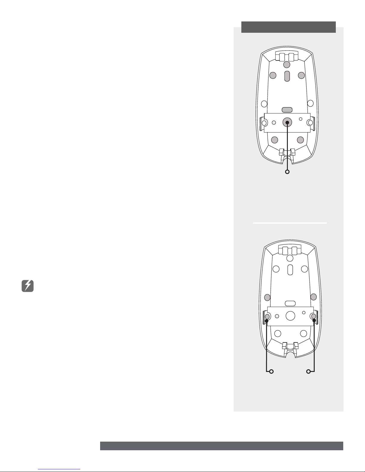
Flat Wall: For flat wall installations, choose from the
mounting hole locations shown in Figure 3. Be sure to
insert a screw in the tamper mounting hole.
Corner: For corner installations, choose from the mounting
hole locations shown in Figure 4. Be sure to insert screws
in the tamper mounting holes.
4. Reinstall the PCB back into the unit. Tighten the PCB
screw to secure it into place.
5. Place the cover back onto the 1122 and tighten the holding
screw back into place.
REPLACE THE BATTERY
1. Remove the holding screw at the lower end of the 1122 case and
gently lift o the cover.
2. Remove the old battery and dispose of it properly. See Figure 2 for
the battery location.
3. Observing polarity, place the new battery in the holder and press
into place.
Note: Use only 3V Lithium CR123 batteries.
4. Place the cover back onto the 1122 and tighten the holding screw
back into place.
Caution: Properly dispose of used batteries. Do not recharge,
disassemble, heat above 212°F (100°C), or incinerate. Risk of fire,
explosion, and burns.
MOUNTING HOLES
Tamper
Mounting Hole
Figure 3: Flat Mounting
Hole Locations
Sensor Reset to Clear LOBAT
When the battery needs to be replaced, a LOBAT message will display on
the keypad. Once the battery is replaced, a sensor reset is required at the
system keypad to clear the LO B AT message.
1. On a Thinline keypad, press and hold “2” for two seconds. On a
touchscreen keypad press RESET.
2. Enter your user code if required.
3. The keypad displays SENSORS OFF followed by SENSORS ON.
1122 INSTALLATION GUIDE | DIGITAL MONITORING PRODUCTS 3
Tamper
Mounting
Holes
Figure 4: Corner Mounting
Hole Locations
Page 4

FCC INFORMATION
This device complies with Part 15 of the FCC Rules. Operation is subject to the following two conditions:
1. This device may not cause harmful interference, and
2. this device must accept any interference received, including interference that may cause undesired operation.
The antenna used for this transmitter must be installed to provide a separation distance of at least 20 cm (7.874 in.) from all persons. It
must not be located or operated in conjunction with any other antenna or transmitter.
Changes or modifications made by the user and not expressly approved by the party responsible for compliance could void the user’s
authority to operate the equipment.
Note: This equipment has been tested and found to comply with the limits for a Class B digital device, pursuant to part 15 of the
FCC Rules. These limits are designed to provide reasonable protection against harmful interference in a residential installation.
This equipment generates, uses and can radiate radio frequency energy and, if not installed and used in accordance with the
instructions, may cause harmful interference to radio communications. However, there is no guarantee that interference will not
occur in a particular installation. If this equipment does cause harmful interference to radio or television reception, which can be
determined by turning the equipment o and on, the user is encouraged to try to correct the interference by one or more of the
following measures:
• Reorient or relocate the receiving antenna.
• Increase the separation between the equipment and receiver.
• Connect the equipment into an outlet on a circuit dierent from that to which the receiver is connected.
• Consult the dealer or an experienced radio/TV technician for help.
Industry Canada Information
This device complies with Industry Canada Licence-exempt RSS standard(s). Operation is subject to the following two conditions:
1. This device may not cause interference, and
2. this device must accept any interference, including interference that may cause undesired operation of the device.
Le présent appareil est conforme aux CNR d’Industrie Canada applicables aux appareils radio exempts de licence. L’exploitation est
autorisée aux deux conditions suivantes:
1. l’appareil ne doit pas produire de brouillage, et
2. l’utilisateur de l’appareil doit accepter tout brouillage radioélectrique subi, même si le brouillage est susceptible d’en
compromettre le fonctionnement.
This system has been evaluated for RF Exposure per RSS-102 and is in compliance with the limits specified by Health Canada Safety
Code 6. The system must be installed at a minimum separation distance from the antenna to a general bystander of 7.87 inches (20 cm)
to maintain compliance with the General Population limits.
L’exposition aux radiofréquences de ce système a été évaluée selon la norme RSS-102 et est jugée conforme aux limites établies par le
Code de sécurité 6 de Santé Canada. Le système doit être installé à une distance minimale de 7.87 pouces (20 cm) séparant l’antenne
d’une personne présente en conformité avec les limites permises d’exposition du grand public.
1122 WIRELESS PIR
MOTION DETECTOR
Specifications
Battery
Life Expectancy 3 Years (normal operation)
Type 3.0V Lithium CR123A
Frequency Range 905-924 MHz
Detection
Range 90 40 x 40 feet
Speed 1 to 5 feet/second
Mounting Height 4.9 to 8.2 feet
Transmit Condition Alarm, Low Battery
Specifications, cont.
Color White
Housing Material Flame retardant ABS
Dimensions 5" Length x 2.6" Width x 1.5" Depth
Certifications
FCC Part 15 Registration ID CCK1122
Industry Canada Registration ID 5251A-1122
Patents
U.S. Patent No. 7,239,236
Designed, engineered,
and manufactured in
Springfield, Missouri
INTRUSION • FIRE • ACCESS • NETWORKS
2500 North Partnership Boulevard
Springfield, Missouri 65803-8877
800-641-4282 | dmp.com
 Loading...