

Page 1
X1-8 ACCESS CONTROL
Power Supply positive
Quick Start Guide
MOUNT THE SYSTEM
The metal enclosure for the X1-8 system must be mounted to a wall, backboard,
or other flat surface. It is not necessary to remove the PCB when installing the
enclosure.
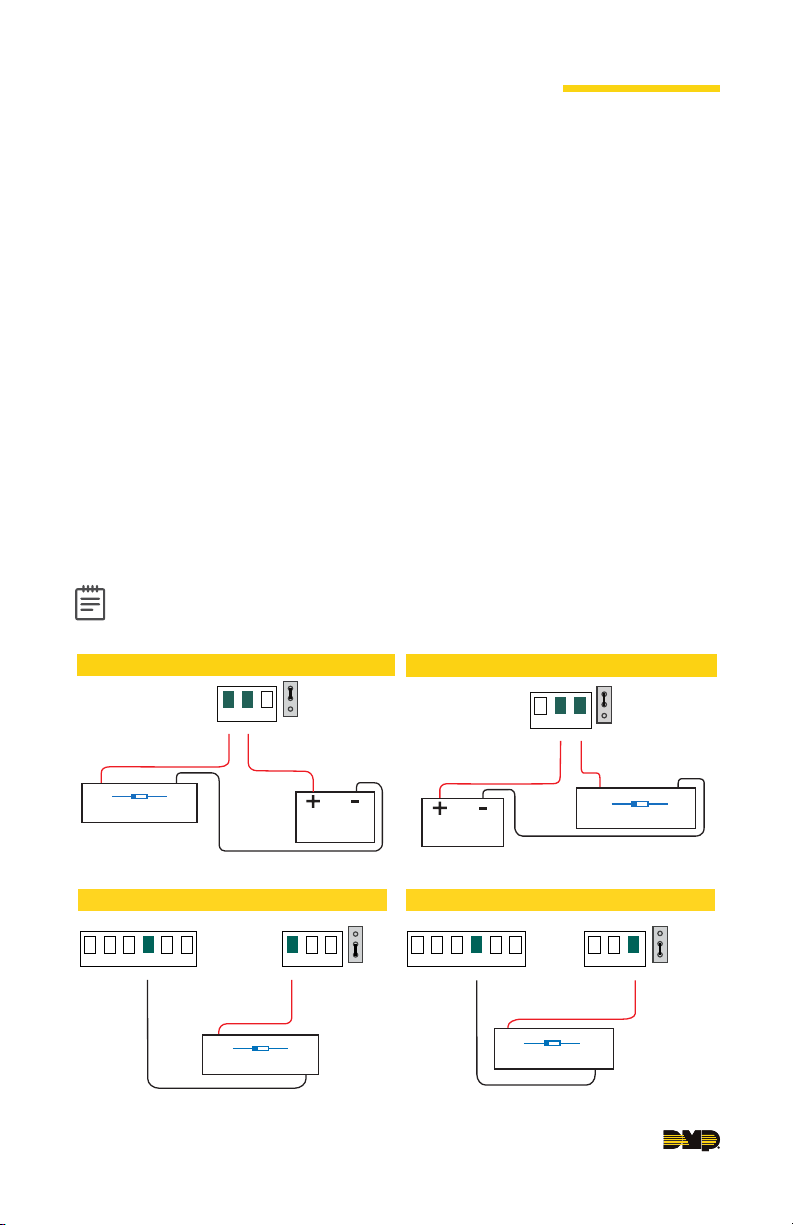
WIRE THE ELECTRONIC LOCK
This section only applies to the X1 Door Controller and the XD Door Controller
Modules.
Form C Relay
The X1 system provides a Form C (SPDT) relay that is rated for 1 Amp.
Diode
Connect the included diode as close to the magnetic lock or door strike as
possible to prevent inductive kickback to the Door Controller. Observe polarity
when connecting the diode.
Wet/Dry Jumper
Putting the jumper on the top two terminals will place it in the dry condition.
Putting the jumper on the bottom two terminals will place it in the wet condition.
Note: The XD Door Controller only wires dry because it does not have a
wet/dry jumper.
Magnetic Lock - Normally Closed and Dry
Magnetic Lock positive
to Terminal NC
Diode
Magnetic Lock
NC
–+
Magnetic Lock negative to
Power Supply negative
C
NO
DRY
Jumper set
WET
to Terminal C
Power Supply
Magnetic Lock - Normally Closed and Wet
Reader 2
R2
W2
BC
G2 LC
B2
Magnetic Lock positive
to Terminal NC
Magnetic Lock
Magnetic Lock negative to
X1 terminal B2
Diode
NC
C
Jumper set
–+
to Dry
DRY
WET
NO
to Wet
Door Strike - Normally Open and Dry
Power Supply positive
Power Supply
Door Strike - Normally Open and Wet
Reader 2
R2
W2
LT-2268 21042 © 2021 Digital Monitoring Products, Inc.
NC
to Terminal C
Door Strike negative to
Power Supply negative
BC
G2 LC
B2
Door Strike positive
to Terminal NO
Diode
DC Door Strike
Door Strike negative to
X1 terminal B2
DRY
Jumper set
WET
NO
C
Door Strike positive
to Terminal NO
Diode
DC Door Strike
NO
NC
C
–+
to Dry
–+
DRY
WET
Jumper set
to Wet
Page 2

CONNECT A CARD READER
The card reader wires the same for the X1 Door Controller and the XD Door
Controller Modules.
The X1 Series system provides direct 12 VDC output to the reader on the RED
terminal connection.
Terminal Name Wiegand Function OSDP Function
R1 & R2 12V+ DC +
W1 & W2 Data 1 B (485 +)
G1 & G2 Data 0 A (485 -)
B1 & B2 12V- (ground) DC -
LC LED Control N/A
BC Wiegand Buzzer Control N/A
WIRE THE INPUTS
The inputs wire the same for the X1 Door Controller and the XD Door Controller
Modules.
Door Switch (DS) - Normally Closed
Connect a door contact or door position switch to
indicate status of door, whether it is open or closed.
Request to Exit (RX) - Normally Open
Connect a motion sensing device or a mechanical
switch to provide RX capability to the system.
Custom Input (CI) - Normally Open
This input triggers a custom action.
Ground (G)
This terminal is the ground for the inputs.
DS RX
+AC/DC- +BAT- R1 W1 G1
CI
G
R2 W2 G2
B1 LC BC
12V NC C
DS RXCIG0102
B2 LC BC
NO
WIRE THE OUTPUTS
This section only applies to the X1 Door Controller.
Use these terminals for local outputs or door alarms
such as sounders, lights, or sirens. These are 12 VDC
outputs.
Aux Output 1 & 2 (O1 & O2)
Attach the negative wire of the device here.
12V+ (12V)
Attach the positive wire of the device here.
X1-8 QUICK START GUIDE | DIGITAL MONITORING PRODUCTS 2
+AC/DC- +BAT- R1 W1 G1
01 02 12V
R2 W2 G2
B1 LC BC
B2 LC BC
DS RX CI G 01 02 12V NC C NO
Page 3
DETERMINE COMMUNICATION
This section only applies to the X1 Door Controller.
For more detailed information, follow the QR code at the end of this guide to see
the full X1-8 Installation and Programming Guide: LT-2289.
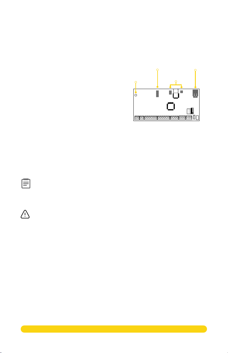
Ethernet Connection
Connect an Ethernet cable from the LAN/
WAN connection to the X1 Ethernet port.
Cellular Connection (Optional)
1. Attach the included stando to the
Door Controller.
2. Plug the Cell Module onto the stando.
3. Plug the Cell Module into the Cell
Header.
4. Attach the Cell Module Antenna cable
to the antenna connector.
5. Run the cable around the 505-12
Power Supply.
6. Attach the antenna with the nut on the inside of the enclosure and the
washers on the inside and the top of the enclosure.
Stando
Location
Cell
Header
Headers
Wi-Fi Connection
If not connecting over Ethernet, the Door Controller will connect over Wi-Fi after
power up.
For installing the Wi-Fi Antenna, follow the QR code at the end of this guide to
see the full X1-8 Installation and Programming Guide: LT-2289.
Note: You can connect over Ethernet or Wi-Fi, but not both at the same
time.
PoE
Ethernet
Port
APPLY POWER
This section only applies to the X1 Door Controller.
Warning: Refer to your local state regulations before connecting to building
power. Wiring methods shall be in accordance with NEC, NFPA72, ANSI, and
with all Authority Having Jurisdiction.
Ground the System
Be sure to secure the green wire lead to an earth ground. Connect to a cold water
pipe, ground rod, or building ground when available. Connection to an electrical
ground or conduit can also be used. Gas pipes or sprinkler pipes should not be used.
Connect AC Power
Connect an unswitched 120 V AC 60 Hz power source to the transformer leads
on the 505-12. Remove desired knockouts for power input.
Wire the Battery
The battery leads for the X1-8 come pre-wired.
3 X1-8 QUICK START GUIDE | DIGITAL MONITORING PRODUCTS
Page 4
CONNECTION SETTINGS
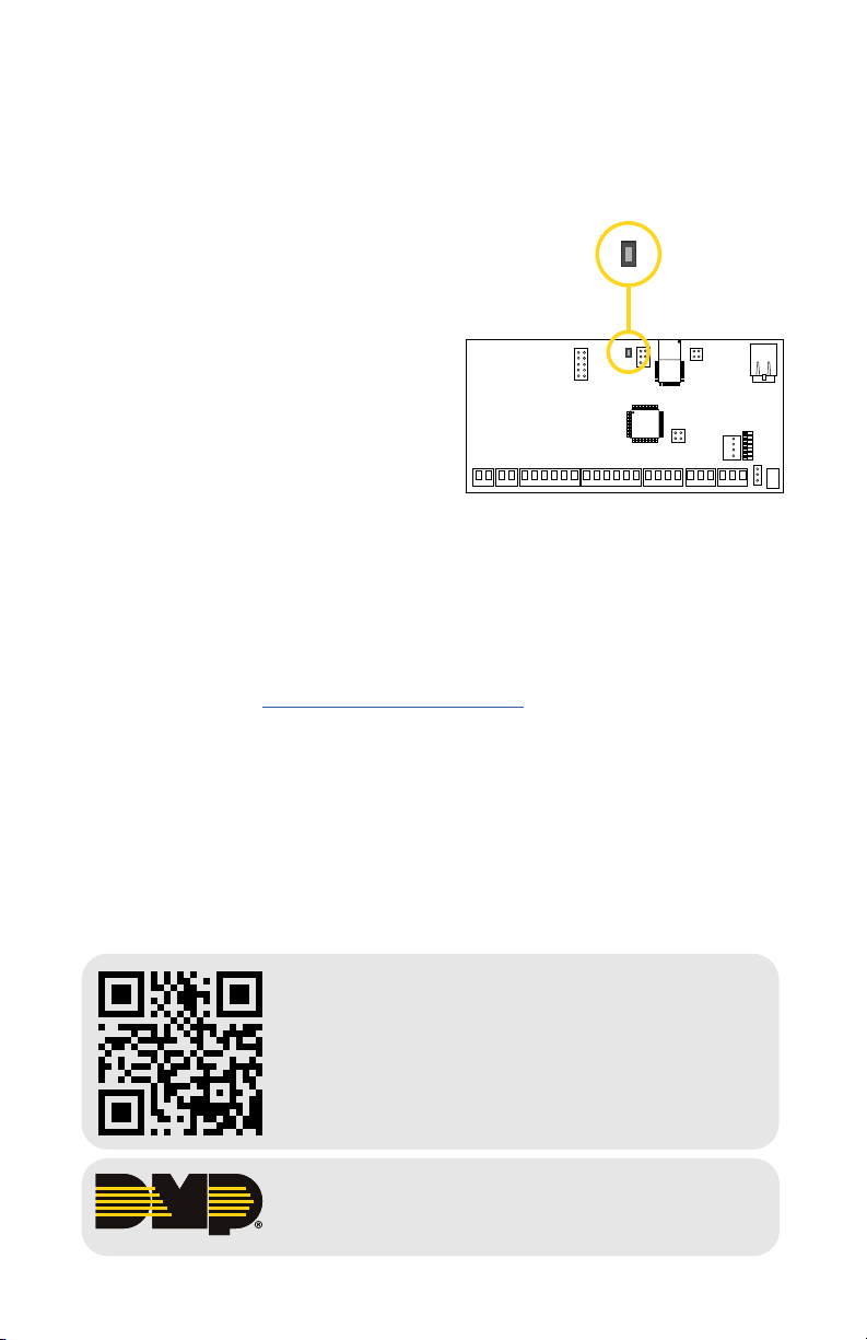
If no network cable is attached, thirty seconds after power up the X1 broadcasts an
SSID of DMPX1 followed by the system’s serial number. No password is required to
join the SSID.
Configure Options
1. Connect to the X1 SSID using a
Wi-Fi LED
device capable of launching a
browser (cell phone, laptop, etc.).
2. Enter 192.168.1.1 into the web
browser.
3. For Wi-Fi, in the Wi-Fi options,
enter the customer’s network
information. For Network, the DHCP
options, make edits to the desired
fields.
R
L
• DHCP: This option is toggled
on as default.
• Static IP: Toggle o DHCP and
enter the information in the
required fields.
4. Select Apply, and the X1 will reset.
Once the X1 has reset, it will automatically connect to the customer’s network
with the updated settings.
PROGRAM IN DEALER ADMIN™
Go to Dealer Admin (dealer.securecomwireless.com) to program the system.
More Information
Follow the QR code for more information.
• X1-8 Installation and Programming Guide
• X1 Series Compliance Guide
INTRUSION • FIRE • A CCESS • NETWORKS
Designed, engineered, and manufactured in Springfield, Missouri
2500 North Partnership Boulevard Springfield, Missouri 65803-8877
800.641.4282 | dmp.com
|
.
 Loading...