

Page 1
TECHNICAL USER MANUAL FOR:
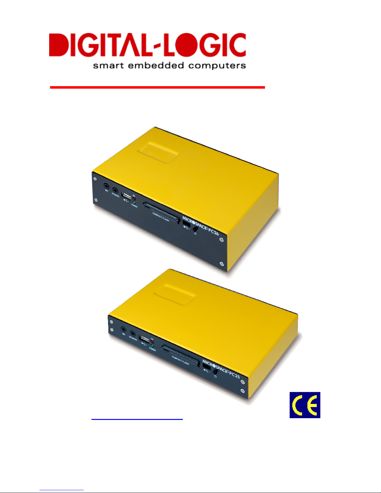
MPC25/L, MPC26/L/A
Nordstrasse 11/F
CH - 4542 Luterbach
Tel.: ++41 (0)32 681 58 00
Fax: ++41 (0)32 681 58 01
Email: support@digitallogic.com
Homepage: http://www.digitallogic.com
Page 2
DIGITAL-LOGIC AG
MPC25/26 Manual V1.1
2
For internal use only:
File: MPC25_26_TechManual_V1.0_NochNichtFreigegeben
Path: R:\HANDBUCH\MPC\MPC25_26\MPC25_26_TechManual_V1.0_NochNichtFreigegeben.doc
COPYRIGHT 2008 BY DIGITAL-LOGIC AG
This publication is protected by copyright and all rights are reserved. No part of this document may be
reproduced, transmitted, transcribed or stored in a retrieval system, in any form or by any means, electronic,
mechanical, optical, manual, or otherwise, without the prior written permission of DIGITAL-LOGIC AG.
The software described herein, together with this document, are furnished under a license agreement and
may be used or copied only in accordance with the terms of that agreement.
About this Manual and How to Use It
This manual is written for the end user / system integrator who plans to install computer systems based on
the MICROSPACE-PC. It is for integrators and programmers of systems based on the MICROSPACEComputer family. This manual describes the system and setup requirements; it provides instructions for
installing and configuring the system. This document contains information on hardware requirements,
interconnections, and details of how to program the system. Please check the Product CD for further
information and manuals.
REVISION HISTORY:
Document
Version
Date/Initials: Modification:
Remarks, News, Attention:
V1.0 10.2008 KUF Initial Version
V1.1 22.04.2009 NAK Aktuelle Fotos eingefügt
ATTENTION!
1. All information in this manual, and the product, are subject to change without prior notice.
2. Read this manual prior to installation of the product.
3. Read the security information carefully prior to installation of the product.
Page 3

DIGITAL-LOGIC AG
MPC25/26 Manual V1.1
3
Table of Contents
1. P
REFACE
........................................................................................................................5
1.1. Trademarks ..................................................................................................................................... 5
1.2. Disclaimer ....................................................................................................................................... 5
1.3. Environmental Protection Statement ........................................................................................... 5
1.4. Who should use this Product ....................................................................................................... 5
1.5. Recycling Information.................................................................................................................... 5
1.6. Technical Support .......................................................................................................................... 5
1.7. Limited Two Year Warranty ........................................................................................................... 6
1.8. Explanation of Symbols................................................................................................................. 7
1.9. Applicable Documents and Standards ........................................................................................ 8
1.10. For Your Safety............................................................................................................................... 9
1.11. RoHS Commitment......................................................................................................................... 9
1.11.1. RoHS Compatible Product Design ........................................................................................ 10
1.11.2. RoHS Compliant Production Process ................................................................................... 10
1.11.3. WEEE Application.................................................................................................................. 10
1.12. Swiss Quality ................................................................................................................................ 11
1.13. The Swiss Association for Quality and Management Systems............................................... 11
1.14. EC – Declaration of Conformity MPC25..................................................................................... 12
1.15. EC – Declaration of Conformity MPC25L................................................................................... 13
1.16. EC – Declaration of Conformity MPC26..................................................................................... 14
1.17. EMV Certificate MPC25/ 26 .......................................................................................................... 15
1.17.1. EMV Test Diagram, Class A MPC25/ 26............................................................................... 16
1.17.2. EMV Test Diagram, Class B MPC25/ 26............................................................................... 16
2. O
VERVIEW
....................................................................................................................17
2.1. Packing List .................................................................................................................................. 17
2.2. System Overview.......................................................................................................................... 17
2.3. Differences between MPC25, MPC26, MPC26A ........................................................................ 18
2.4. Assembly Options........................................................................................................................ 18
2.5. Functional Block Diagram ........................................................................................................... 19
2.6. Technical Specifications ............................................................................................................. 20
2.7. MPC25/26 Incompatibilities to a Standard PC/AT..................................................................... 23
2.8. Related Application Notes........................................................................................................... 23
3. S
AFETY REGULATIONS
..................................................................................................24
3.1. Safety: Power-On Indicator ......................................................................................................... 24
3.2. Safety: Coded and Marked Connectors..................................................................................... 24
3.3. Protection of the Supply Input Current...................................................................................... 24
3.4. Safety: Wrong Polarization on the Power Input........................................................................ 24
3.5. Safety: Protection of the Output Currents................................................................................. 24
3.6. Safety: Load Dump Protection in 12V systems ........................................................................ 24
3.7. Ground Potential .......................................................................................................................... 25
3.8. Power On/Off Switch.................................................................................................................... 25
3.9. Safety: Batteries Inside the Device ............................................................................................ 25
3.10. Protection against Over-Heating ................................................................................................ 26
3.11. Mechanical Safety: Safe Assembly and Mounting ................................................................... 26
3.12. Environmental Safety: At 25°C No “Hot” Surfaces................................................................... 26
3.13. Environmental Safety: No Release of Toxins............................................................................ 26
3.14.
Environmental Safety: Laser Devices.................................................................................... 26
3.15.
Environmental Safety: Noise Emission ................................................................................. 26
3.16. Environmental Safety: Hazardous Environs ............................................................................. 27
3.17. Environmental Safety: Humidity and Water Spray ................................................................... 27
3.18. Safety: Independent Software..................................................................................................... 27
3.19. Safety: Recycling the Computer System................................................................................... 27
3.20. Safety: Static Electricity .............................................................................................................. 27
3.21. Safety: Operator Security ............................................................................................................ 27
4. F
UNCTIONS
...................................................................................................................28
4.1. Connectors ................................................................................................................................... 28
Page 4

DIGITAL-LOGIC AG
MPC25/26 Manual V1.1
4
4.1.1.
Front of the MPC25 / 26 / L ................................................................................................... 28
4.1.2.
Rear of the MPC25 / 25L....................................................................................................... 29
4.1.3.
Front of the MPC26/26A........................................................................................................ 30
4.1.4.
Rear of the MPC26 ................................................................................................................ 31
4.1.5.
Rear of the MPC26A ............................................................................................................. 32
4.1.6.
Power Supply Connector....................................................................................................... 33
4.2. DC-Power Input Specifications ................................................................................................... 33
4.2.1.
Nominal DC-Power Input Voltage.......................................................................................... 33
4.2.2.
Minimal DC-Power Input Voltage Specification..................................................................... 33
4.3. Hard Disk 2.5” - Standard Type .................................................................................................. 34
4.4. WLAN Option ................................................................................................................................ 35
5. H
ARDWARE INSTALLATION
............................................................................................36
5.1. Install an additional PCI/104 card (MPC26/A only) ................................................................... 36
6. P
REPARE THE COMPUTER SYSTEM
.................................................................................37
6.1. Print the Detailed Manuals from the Product CD...................................................................... 37
6.2. Jumper Configuration.................................................................................................................. 37
6.3. Connect the Peripherals to the System ..................................................................................... 37
7. P
OWER-ON THE SYSTEM
...............................................................................................38
7.1. BIOS Setup.................................................................................................................................... 39
7.2. Boot up the Operating System and Install the Drivers............................................................. 39
7.3. FreeDOS, DSLinux und ELinOS Bootflash................................................................................ 39
7.3.1.
Free DOS............................................................................................................................... 39
7.3.2.
SLAX LINUX .......................................................................................................................... 39
7.3.3.
ELinOS Demo........................................................................................................................ 39
8. DIMENSIONS AND DIAGRAMS ................................................................................40
8.1. Front Views ................................................................................................................................... 40
8.2. Rear Views .................................................................................................................................... 40
8.3. Top Views......................................................................................Fehler! Textmarke nicht definiert.
8.4. Side Views..................................................................................................................................... 40
8.5. Mounting Plate MPC20/20L/21/21C/25/26/26A........................................................................... 40
8.6. Front Plate MPC25........................................................................................................................ 40
9. C
ORE
BIOS .................................................................................................................41
9.1. BIOS History ................................................................................................................................. 41
9.2. Setup Menu Screens and Navigation......................................................................................... 41
9.3. BIOS Setup.................................................................................................................................... 42
9.3.1.
Main Menu ............................................................................................................................. 42
10. B
OOT FROM
LAN – PXE & WOL (W
AKE ON
LAN).....................................................43
10.1. MPC25WOL and MPC26WOL Not implemented in the moment. Is planed for 2009. ........... 43
10.1.1. Boot from LAN (PXE) ............................................................................................................ 43
10.1.2. Wake On LAN (WOL) ............................................................................................................ 46
10.1.3. Boot from LAN (PXE) ............................................................................................................ 48
10.1.4. PXE License Order Form (for MPC25 / MPC25L / MPC26................................................... 50
11. I
NDEX
.......................................................................................................................52
Page 5

DIGITAL-LOGIC AG
MPC25/26 Manual V1.1
5
1. P
REFACE
The information contained in this document has been carefully checked and is believed to be accurate; it is
subject to change without notice. Product advances mean that some specifications may have changed.
DIGITAL-LOGIC AG assumes no responsibility for any inaccuracies, or the consequences thereof, that may
appear in this manual. Furthermore, DIGITAL-LOGIC AG does not accept any liability arising from the use or
application of any circuit or product described herein.
1.1. Trademarks
DIGITAL-LOGIC, DIGITAL-LOGIC-Logo, MICROSPACE, and smartModule are registered trademarks
owned worldwide by DIGITAL-LOGIC AG, Luterbach (Switzerland). In addition, this document may include
names, company logos, and registered trademarks which are, therefore, proprietary to their respective
owners.
1.2. Disclaimer
DIGITAL-LOGIC AG makes no representations or warranties with respect to the contents of this manual, and
specifically disclaims any implied warranty of merchantability or fitness, for any particular purpose. DIGITALLOGIC AG shall, under no circumstances, be liable for incidental or consequential damages or related
expenses resulting from the use of this product, even if it has been notified of the possibility of such damage.
1.3. Environmental Protection Statement
This product has been manufactured to satisfy environmental protection requirements wherever possible.
Many of the components used (structural parts, printed circuit boards, connectors, batteries, etc.) are
capable of being recycled. Final disposal of this product after its service life must be accomplished in
accordance with applicable country, state, or local laws or regulations.
1.4. Who should use this Product
Electrical engineers with know-how in PC-technology.
Because of the complexity and the variability of PC-technology, we cannot guarantee that the product
will work in any particular situation or set-up. Our technical support will try to help you find a solution.
Pay attention to electrostatic discharges; use a CMOS protected workplace.
Power supply must be OFF when working on the board or connecting any cables or devices.
1.5. Recycling Information
All components within this product fulfill the requirements of the RoHS (Restriction of Hazardous Substances
Directive). The product is soldered with a lead free process.
1.6. Technical Support
1. Contact your local DIGITAL-LOGIC Technical Support, in your country.
2. Use the Internet Support Request form at http://support.digitallogic.ch/ embedded products New
Support Request
Support requests are only accepted with detailed information about the product (i.e., BIOS-, Boardversion)!
Page 6

DIGITAL-LOGIC AG
MPC25/26 Manual V1.1
6
1.7. Limited Two Year Warranty
DIGITAL-LOGIC AG guarantees the hardware and software products it manufactures and produces to be
free from defects in materials and workmanship for two years following the date of shipment from DIGITALLOGIC AG, Switzerland. This warranty is limited to the original purchaser of the product and is not
transferable.
During the two year warranty period, DIGITAL-LOGIC AG will repair or replace, at its discretion, any
defective product or part at no additional charge, provided that the product is returned, shipping prepaid, to
DIGITAL-LOGIC AG. All replaced parts and products become property of DIGITAL-LOGIC AG.
Before returning any product for repair, direct customers of DIGITAL-LOGIC AG, Switzerland
are required to register a RMA (Return Material Authorization) number in the Support Center at
http://support.digitallogic.ch/
All other customers must contact their local distributors for returning defective materials.
This limited warranty does not extend to any product which has been damaged as a result of accident,
misuse, abuse (such as use of incorrect input voltages, wrong cabling, wrong polarity, improper or
insufficient ventilation, failure to follow the operating instructions that are provided by DIGITAL-LOGIC AG or
other contingencies beyond the control of DIGITAL-LOGIC AG), wrong connection, wrong information or as
a result of service or modification by anyone other than DIGITAL-LOGIC AG. Nor if the user has insufficient
knowledge of these technologies or has not consulted the product manuals or the technical support of
DIGITAL-LOGIC AG and therefore the product has been damaged.
Empty batteries (external and onboard), as well as all other battery failures, are not covered by this
manufacturer’s limited warranty.
Except, as directly set forth above, no other warranties are expressed or implied, including, but not limited to,
any implied warranty of merchantability and fitness for a particular purpose, and DIGITAL-LOGIC AG
expressly disclaims all warranties not stated herein. Under no circumstances will DIGITAL-LOGIC AG be
liable to the purchaser or any user for any damage, including any incidental or consequential damage,
expenses, lost profits, lost savings, or other damages arising out of the use or inability to use the product.
Page 7

DIGITAL-LOGIC AG
MPC25/26 Manual V1.1
7
1.8. Explanation of Symbols
CE Conformity
This symbol indicates that the product described in this manual is in compliance with all
applied CE standards.
Caution, Electric Shock!
This symbol and title warn of hazards due to electrical shocks (> 60V) when touching
products or parts of them. Failure to observe the precautions indicated and/or prescribed by
the law may endanger your life/health and/or result in damage to your equipment.
Caution, Electric Shock!
This symbol and title warn of hazards due to electrical shocks (> 32V) when touching
products or parts of them. Failure to observe the precautions indicated and/or prescribed by
the law may endanger your life/health and/or result in damage to your equipment
Warning, ESD Sensitive Device!
This symbol and title inform that electronic boards and their components are sensitive to
Electro Static Discharge (ESD). In order to ensure product integrity at all times, care must
always be taken while handling and examining this product.
Attention!
This symbol and title emphasize points which, if not fully understood and taken into
consideration by the reader, may endanger your health and/or result in damage to your
equipment.
Note...
This symbol and title emphasize aspects the user should read through carefully for his, or
her, own advantage.
Warning, Heat Sensitive Device!
This symbol indicates a heat sensitive component.
Safety Instructions
This symbol shows safety instructions for the operator to follow.
This symbol warns of general hazards from mechanical, electrical,
and/or chemical failure. This may endanger your life/health and/or
result in damage to your equipment.
Page 8

DIGITAL-LOGIC AG
MPC25/26 Manual V1.1
8
1.9. Applicable Documents and Standards
The following publications are used in conjunction with this manual. When any of the referenced
specifications are superseded by an approved revision, that revision shall apply. All documents may be
obtained from their respective organizations.
Advanced Configuration and Power Interface Specification Revision 2.0c, August 25, 2003 Copyright
© 1996-2003 Compaq Computer Corporation, Intel Corporation, Microsoft Corporation, Phoenix
Technologies Ltd., Toshiba Corporation. All rights reserved. http://www.acpi.info/
ANSI/TIA/EIA-644-A-2001: Electrical Characteristics of Low Voltage Differential Signaling (LVDS)
Interface Circuits, January 1, 2001. http://www.ansi.org/
ANSI INCITS 361-2002: AT Attachment with Packet Interface - 6 (ATA/ATAPI-6), November 1, 2002.
http://www.ansi.org/
ANSI INCITS 376-2003: American National Standard for Information Technology – Serial Attached
SCSI (SAS), October 30, 2003. http://www.ansi.org/
Audio Codec ’97 Revision 2.3 Revision 1.0, April 2002 Copyright © 2002 Intel Corporation. All rights
reserved. http://www.intel.com/labs/media/audio/
Display Data Channel Command Interface (DDC/CI) Standard (formerly DDC2Bi) Version 1, August
14, 1998 Copyright © 1998 Video Electronics Standards Association. All rights reserved.
http://www.vesa.org/summary/sumddcci.htm
ExpressCard Standard Release 1.0, December 2003 Copyright © 2003 PCMCIA. All rights reserved.
http://www.expresscard.org/
IEEE 802.3-2002, IEEE Standard for Information technology, Telecommunications and information
exchange between systems–Local and metropolitan area networks–Specific requirements – Part 3:
Carrier Sense Multiple Access with Collision Detection (CSMA/CD) Access Method and Physical
Layer Specifications. http://www.ieee.org
IEEE 802.3ae (Amendment to IEEE 802.3-2002), Part 3: Carrier Sense Multiple Access with Collision
Detection (CSMA/CD) Access Method and Physical Layer Specifications, Amendment: Media Access
Control (MAC) Parameters, Physical Layers, and Management Parameters for 10 GB/s Operation.
http://www.ieee.org
Intel Low Pin Count (LPC) Interface Specification Revision 1.1, August 2002 Copyright © 2002 Intel
Corporation. All rights reserved. http://developer.intel.com/design/chipsets/industry/lpc.htm
PCI Express Base Specification Revision 1.1, March 28, 2005, Copyright © 2002-2005 PCI Special
Interest Group. All rights reserved. http://www.pcisig.com/
PCI Express Card Electromechanical Specification Revision 1.1, March 28, 2005, Copyright © 2002-
2005 PCI Special Interest Group. All rights reserved. http://www.pcisig.com/
PCI Local Bus Specification Revision 2.3, March 29, 2002 Copyright © 1992, 1993, 1995, 1998, 2002
PCI Special Interest Group. All rights reserved. http://www.pcisig.com/
PCI-104 Specification, Version V1.0, November 2003. All rights reserved. http://www.pc104.org
PICMG® Policies and Procedures for Specification Development, Revision 2.0, September 14, 2004,
PCI Industrial Computer Manufacturers Group (PICMG®), 401 Edgewater Place, Suite 500,
Wakefield, MA 01880, USA, Tel: 781.224.1100, Fax: 781.224.1239. http://www.picmg.org/
Serial ATA: High Speed Serialized AT Attachment Revision 1.0a January 7, 2003 Copyright © 2000-
2003, APT Technologies, Inc, Dell Computer Corporation, Intel Corporation, Maxtor Corporation,
Seagate Technology LLC. All rights reserved.
http://www.sata-io.org/
Page 9
DIGITAL-LOGIC AG
MPC25/26 Manual V1.1
9
Smart Battery Data Specification Revision 1.1, December 11, 1998. www.sbs-forum.org
System Management Bus (SMBus) Specification Version 2.0, August 3, 2000 Copyright © 1994, 1995,
1998, 2000 Duracell, Inc., Energizer Power Systems, Inc., Fujitsu, Ltd., Intel Corporation, Linear
Technology Inc., Maxim Integrated Products, Mitsubishi Electric Semiconductor Company, PowerSmart, Inc., Toshiba Battery Co. Ltd., Unitrode Corporation, USAR Systems, Inc. All rights reserved.
http://www.smbus.org/
Universal Serial Bus Specification Revision 2.0, April 27, 2000 Copyright © 2000 Compaq Computer
Corporation, Hewlett-Packard Company, Intel Corporation, Lucent Technologies Inc., Microsoft
Corporation, NEC Corporation, Koninklijke Philips Electronics N.V. All rights reserved.
http://www.usb.org/
1.10. For Your Safety
Your new DIGITAL-LOGIC product was developed and tested carefully to provide all features
necessary to ensure its compliance with electrical safety requirements. It was also designed for a
long, fault-free life. However, this life expectancy can be drastically reduced by improper treatment
during unpacking and installation. Therefore, in the interest of your own safety and for the correct
operation of your new DIGITAL-LOGIC product, please comply with the following guidelines.
Attention!
All work on this device must only be carried out by sufficiently skilled personnel.
Caution, Electric Shock!
Before installing your new DIGITAL-LOGIC product, always ensure that your mains power is
switched off. This applies also to the installation of piggybacks or peripherals. Serious
electrical shock hazards can exist during all installation, repair and maintenance operations
with this product. Therefore, always unplug the power cable and any other cables which
provide external voltage before performing work.
Warning, ESD Sensitive Device!
Electronic boards and their components are sensitive to static electricity. In order to ensure
product integrity at all times, be careful during all handling and examinations of this product.
1.11. RoHS Commitment
DIGITAL-LOGIC AG is committed to develop and produce environmentally friendly products according to the
Restriction of Hazardous Substances (RoHS) Directive (2002/95/EC) and the Waste Electrical and Electronic
Equipment (WEEE) Directive (2002/96/EC) established by the European Union. The RoHS directive was
adopted in February 2003 by the European Union and came into effect on July 1, 2006. It is not a law but a
directive, which restricts the use of six hazardous materials in the manufacturing of various types of
electronic and electrical equipment. It is closely linked with the Waste Electrical and Electronic Equipment
Directive (WEEE) 2002/96/EC, which has set targets for collection, recycling and recovery of electrical goods
and is part of a legislative initiative to solve the problem of huge amounts of toxic e-waste.
Each European Union member state is adopting its own enforcement and implementation policies using the
directive as a guide. Therefore, there could be as many different versions of the law as there are states in
the EU. Additionally, non-EU countries like China, Japan, or states in the U.S. such as California may have
their own regulations for green products, which are similar, but not identical, to the RoHS directive.
Page 10

DIGITAL-LOGIC AG
MPC25/26 Manual V1.1
10
RoHS is often referred to as the "lead-free" directive but it restricts the use of the following substances:
Lead
Mercury
Cadmium
Chromium VI
PBB and PBDE
The maximum allowable concentration of any of the above mentioned substances is 0.1% (except for
Cadmium, which is limited to 0.01%) by weight of homogeneous material. This means that the limits do not
apply to the weight of the finished product, or even to a component but to any single substance that could
(theoretically) be separated mechanically.
1.11.1. RoHS Compatible Product Design
All DIGITAL-LOGIC standard products comply with RoHS legislation.
Since July 1, 2006, there has been a strict adherence to the use of RoHS compliant electronic and
mechanical components during the design-in phase of all DIGITAL-LOGIC standard products.
1.11.2. RoHS Compliant Production Process
DIGITAL-LOGIC selects external suppliers that are capable of producing RoHS compliant devices. These
capabilities are verified by:
1. A confirmation from the supplier indicating that their production processes and resulting devices are
RoHS compliant.
2. If there is any doubt of the RoHS compliancy, the concentration of the previously mentioned
substances in a produced device will be measured. These measurements are carried out by an
accredited laboratory.
1.11.3. WEEE Application
The WEEE directive is closely related to the RoHS directive and applies to the following devices:
Large and small household appliances
IT equipment
Telecommunications equipment (although infrastructure equipment is exempt in some countries)
Consumer equipment
Lighting equipment – including light bulbs
Electronic and electrical tools
Toys, leisure and sports equipment
Automatic dispensers
It does not apply to fixed industrial plants and tools. The compliance is the responsibility of the company that
brings the product to market, as defined in the directive. Components and sub-assemblies are not subject to
product compliance. In other words, since DIGITAL-LOGIC does not deliver ready-made products to end
users the WEEE directive is not applicable for DIGITAL-LOGIC. Users are nevertheless encouraged to
properly recycle all electronic products that have reached the end of their life cycle.
Page 11

DIGITAL-LOGIC AG
MPC25/26 Manual V1.1
11
1.12. Swiss Quality
100% Made in Switzerland
DIGITAL-LOGIC is a member of "Swiss-Label"
This product was not manufactured by employees earning piecework wages
This product was manufactured in humane work conditions
All employees who worked on this product are paid customary Swiss market wages and are insured
ISO 9000:2001 (quality management system)
1.13. The Swiss Association for Quality and Management
Systems
The Swiss Association for Quality and Management Systems (SQS) provides certification and assessment
services for all types of industries and services. SQS certificates are accepted worldwide thanks to
accreditation by the Swiss Accreditation Service (SAS), active membership in the International Certification
Network, IQNet, and co-operation contracts/agreements with accredited partners.
www.sqs.ch
The SQS Certificate ISO 9001:2000 has been issued to DIGITAL-LOGIC AG, the entire company, in the field
of development, manufacturing and sales of embedded computer boards, embedded computer modules and
computer systems. The certification is valid for three years at which time an audit is performed for
recertification.
Page 12
DIGITAL-LOGIC AG
MPC25/26 Manual V1.1
12
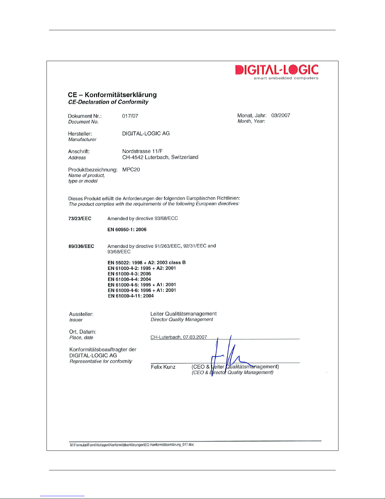
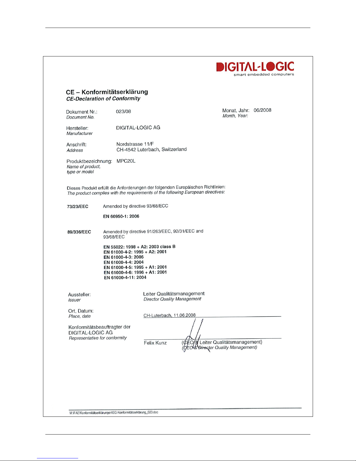
1.14. EC – Declaration of Conformity MPC25
Page 13
DIGITAL-LOGIC AG
MPC25/26 Manual V1.1
13
1.15. EC – Declaration of Conformity MPC25L
Page 14
DIGITAL-LOGIC AG
MPC25/26 Manual V1.1
14
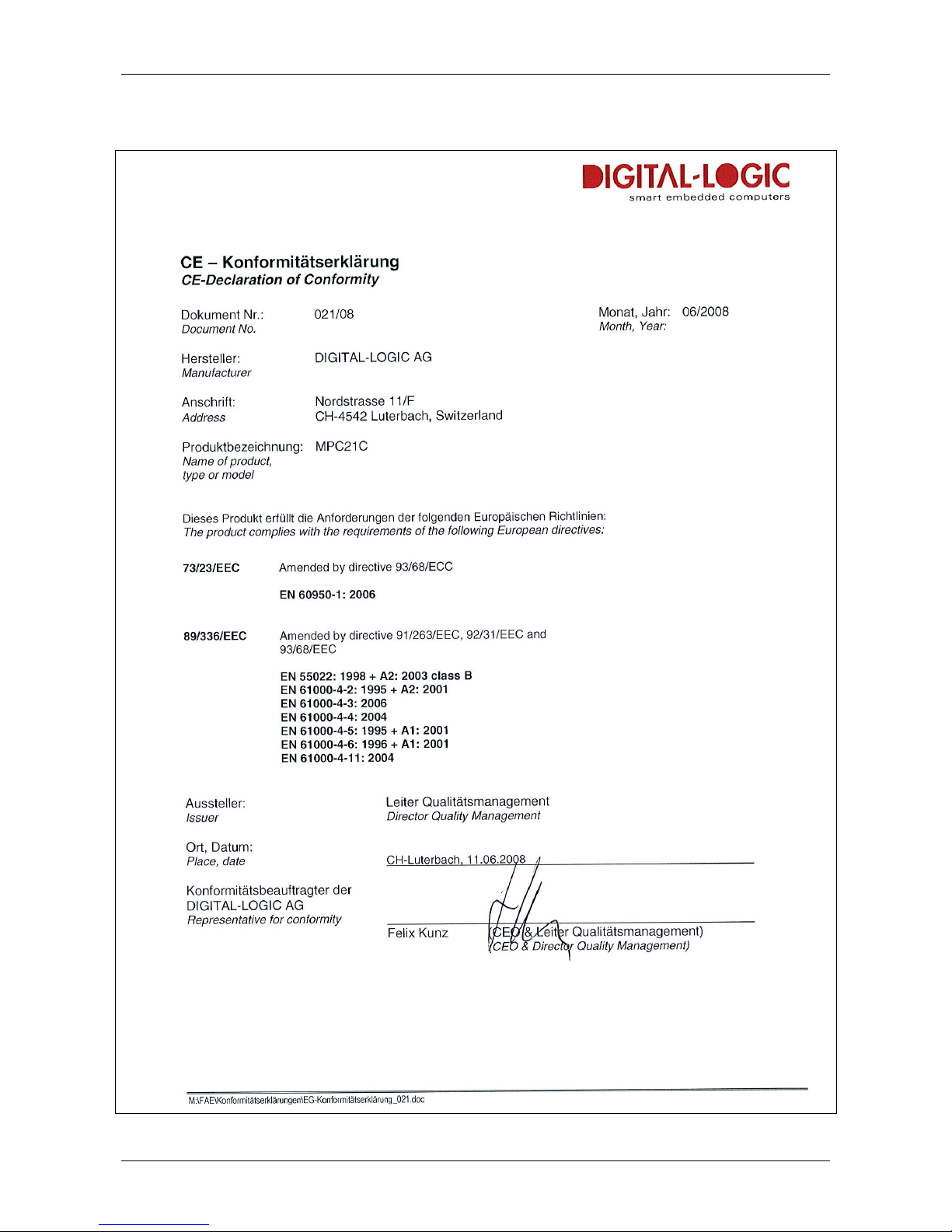
1.16. EC – Declaration of Conformity MPC26
Page 15
DIGITAL-LOGIC AG
MPC25/26 Manual V1.1
15
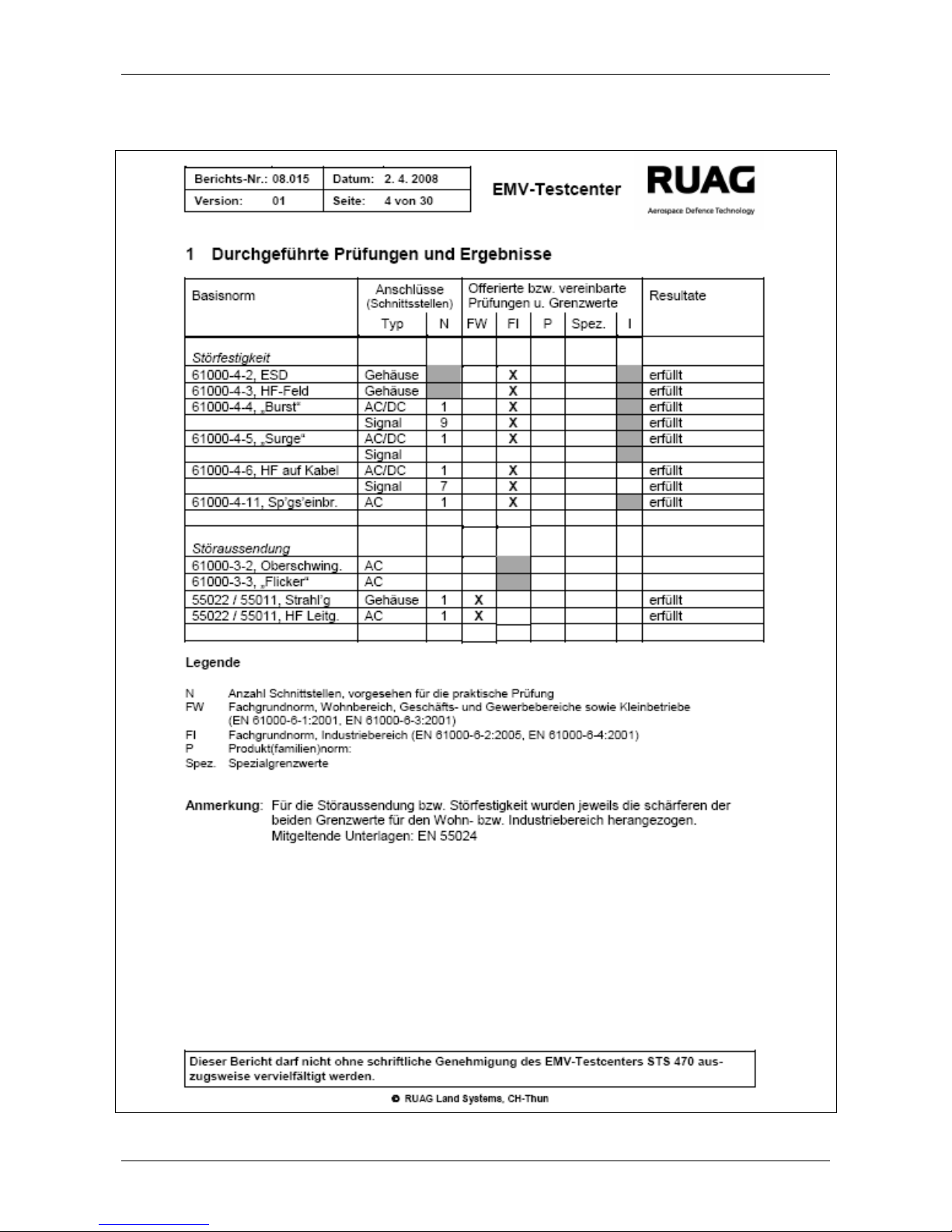
1.17. EMV Certificate MPC25/ 26
Page 16

DIGITAL-LOGIC AG
MPC25/26 Manual V1.1
16
1.17.1. EMV Test Diagram, Class A MPC25/ 26
1.17.2. EMV Test Diagram, Class B MPC25/ 26
Page 17

DIGITAL-LOGIC AG
MPC25/26 Manual V1.1
17
2. O
VERVIEW
2.1. Packing List
After opening the box, check that the following items from the packing list are included:
MICROSPACE-PC25x/26x
Technical User Manual
CD with drivers and documentation
2.2. System Overview
The MICROSPACE-PC25/26 is a miniaturized PC system incorporating the major elements of a PC/AT
compatible computer. It includes standard PC/AT compatible elements, such as:
Intel Atom Z510 (1.1GHz) or Z530 (1.6GHz)
1024k L2 Cache
DDR2-RAM Memory 0.5 to 2Gbyte soldered
Option: hard disk: SATA 250GByte
CompactFlash Type II socket
Direct-X compatible video controller XVGA with up to 256MByte video memory
VGA video
USB controller with up to 6 channels (5x external – 1x internal [not assembled])
Audio stereo Mic in and stereo line out
10-20V DC supply input
Fan-less low power system
MINI-PCIexpress socket
First (1GB/s) and second (100MB/s) LAN
● MPC25L: only 1 LAN
Boot from LAN (PXE)
256M CompactFlash boot medium with SLAX LINUX and Free DOS
● MPC25L: not available
Additional functions of the MPC25 models:
COM1 and COM2
PCI/104 expansion (1 slot)
Additional functions of the MPC26A:
COM1, COM2, COM3, COM4
PCI/104 expansion (1 slot)
Page 18

DIGITAL-LOGIC AG
MPC25/26 Manual V1.1
18
2.3. Differences between MPC25, MPC26, MPC26A
The product has different functions:
Option MPC25 MPC25L MPC26 MPC26A
Video Input
COM1 yes yes
COM2 internal yes yes
COM3 Yes
COM4 Yes
LPT1 - PCI/104 Expansion 1 slot 1 slot
2.4. Assembly Options
The product has different assembly options. Ask the factory for the detailed information about the currently
available options and combination of options.
MPC25/26:
Option Part No. Comments
Hard disk drive 250GB 807466 O Option
Hard disk drive 40GB ext. 807462 O Optional HD with -25°C to +70°C
Power supply adapter 812029 O Power supply 60Watt
Wireless LAN 812048 O Mini-PCIexpress WLAN module
U = Upgrade, D = Downgrade, O = Option
Page 19

DIGITAL-LOGIC AG
MPC25/26 Manual V1.1
19
2.5. Functional Block Diagram
The diagram provides additional information concerning board functionality.
Page 20

DIGITAL-LOGIC AG
MPC25/26 Manual V1.1
20
2.6. Technical Specifications
CPU Specifications
MPC25/26 Intel Atom Z510 / Z530 CPU
Compatibility 80x86 CPU
1st Level Cache 16k data and 16k code
2nd Level Cache 1024kByte
Socket Soldered directly
Clock 1.1GHz / 1.6GHz
Performance
FSB 100MHz
FPU Integrated
Chipset Specifications
Northbridge US15W
Southbridge US15W
LAN 1 Gbit Intel 82551QM
LAN 100 Mbit Intel 82574L
Audio Integrated AC97
Firewire IEEE1394 Video Intel US15W integrated videocontroller
Frame Grabber / Video Input None
Memory Specifications
Main Memory DDR2-SDRAM, 64bit, soldered: 0.5 / 1 / 2Gbyte
Flash BIOS 256kByte Flash
Setup EEPROM 2kByte for CMOS backup in battery-less applications
Flash Video BIOS Serial flash
Video RAM 16MByte
Video Controller Specifications
Controller Intel US15W video controller
Video Memory Up to 256MByte
Channel 1 CRT VGA 320x240 up to 1640x1280 pixels
Boot-up Resolution 640x480 / 800x600 / 1024x768 selectable
2D/3D, X10 Graphics Integrated accelerator
External Interface Specifications
Video Interfaces DVI Videooutput
TV Interfaces None
USB 2.0 1 front, 4 rear, 1 internal (not assembled)
IEEE1394 None
LPT1 COM1 Only MPC26: RS232
COM2 Only MPC26: RS232
Keyboard -Mouse -Audio Stereo I/O
Page 21

DIGITAL-LOGIC AG
MPC25/26 Manual V1.1
21
Power Management
Atom / US15W The US15W supports ACPI and APM Version 1.2.
The following ACPI Sleep States are supported:
S1 Sleep with CPU content.
S4 Hibernation (LED* is blinking) with transition to S5.
S5-G2 Power Off ( LED* is blinking).
The device can be switched on by the Main Button
(or with WOL if available).
S5-G3 Power Off (mechanically)
* = if available
Power Supply Specifications
Input Nom. 12V VDC (range 10V to 20VDC)
Protection Load dump resistant, wrong polarity resistant, EMI filtered
Specification MIL-STD-1275 compliant
Running Typical
Running with HDD Typical
Power-off Standby Typical
Power Consumption @ 18V
Description
MPC25
w/
HDD
w/o
HDD
w/
HDD
w/o
HDD
Power ON (BIOS setup)
368mA 344mA 393mA 372mA
Power OFF (green LED is blinking)
30mA 30mA 57mA 57mA
Power OFF (LAN cable is connected - LINK LED glows)
66mA 66mA
MPC26
w/
HDD
w/o
HDD
w/
HDD
w/o
HDD
Power ON (BIOS setup)
456mA 433mA 420mA 397mA
Power OFF (green LED is blinking)
45mA 45mA 57mA 57mA
Power OFF (LAN cable is connected - LINK LED glows)
67mA 67mA
Physical Characteristics Specifications
Dimensions Length: 165 mm
Depth: 110 mm
Height:
MPC25 27 mm
MPC26/A/L 46 mm
Weight MPC25 0.5 kg
MPC26 0.7 kg
Page 22

DIGITAL-LOGIC AG
MPC25/26 Manual V1.1
22
Operating Environment Specifications
Relative Humidity 5 - 90% non-condensing
IEC68-2-30 at -+5 to +50°C operating
Vibration Operating IEC68-2-6 10-50Hz, 0.075mm and 55-500Hz, 1.0G
Vibration Non-operating IEC68-2-6 10-50Hz, 0.15mm and 55-500Hz, 2.0G
Shock Operating IEC68-2-27 10G, 11ms ½ sine
Shock Non-operating IEC68-2-27 50G, 11ms, ½ sine
Altitude IEC68-2-13 4571meter operating
Temperature Operating IEC68-2-1,2,14 (see separate table below)
Temperature Storage IEC68-2-1,2,14: -40°C to +70°C
Operating Temperature Specifications
Without hard drive -25°C to +70°C
With standard hard drive 0°C to +50°C
With extended temp. hard drive -25°C to +70°C
EMI / EMC Tests Specifications
EMC Emission EN61000-6-2:2001
Conducted disturbance EN55022 Class B
Radiated disturbance EN55022 Class B
EMC Immunity EN61000-6-2
Electro-Static Discharge (ESD) EN61000-4-2
Voltage = 4kV contact / 8kV air
Criteria A
Radiated RF field EN61000-4-3
Level = 10V/m
Criteria A
Electrical fast transients (burst) EN61000-4-4
Grade 2: DC-Power lines = 1000V (5/50ns)
Grade 2: AC-Power lines = 2000V (5/50ns)
Grade 2: Signal lines = 500V (5/50ns)
Criteria B
Surge EN61000-4-5
Grade 2: DC-Power lines = 1kV, (1.2/50us)
Grade 2: AC-Power lines = 2kV, (1.2/50us)
Criteria B
Conducted disturbances EN61000-4-6
Voltage = 10V coupled by case
Criteria A
Security:
e1: Not planned
UL Not planned
ETL 301 Not planned
SEV
Safety AR385-16
Page 23

DIGITAL-LOGIC AG
MPC25/26 Manual V1.1
23
2.7. MPC25/26 Incompatibilities to a Standard PC/AT
None.
2.8. Related Application Notes
Application Notes are available at http://www.digitallogic.com support, or on any DIGITAL-LOGIC
Application CD.
# Description
Page 24

DIGITAL-LOGIC AG
MPC25/26 Manual V1.1
24
3. S
AFETY REGULATIONS
Safety verifications follow the guidelines adapted from the US Army Communication and Electronics
Command Supplement (1992 version) 1 to AR385-16.
3.1. Safety: Power-On Indicator
The green power indicator is located in the front of the computer system. [MIL-STD-1472D]
3.2. Safety: Coded and Marked Connectors
All connectors (plugs and receptacles) are coded and marked to prevent insertion of the wrong plug into a
receptacle or other mating unit [MIL-STD-1472D]. Depending on the mounted replicator unit, the connectors
are PC-Style, DSUB or MIL versions. The male connectors are de-energized when disconnected. [MIL-STD454M]
3.3. Protection of the Supply Input Current
Note…
The computer system protects the internal supply from overcurrent by an external fuse of 6.3amp.
In case of an overcurrent the fuse opens the main circuit and interrupts the fault current. [MILSTD-454M]
3.4. Safety: Wrong Polarization on the Power Input
Attention!
The supply input is protected against wrong polarization with a serial diode. This diode withstands
current up to 28Volts.
3.5. Safety: Protection of the Output Currents
There is no overcurrent protection on any peripheral port. The following table shows the maximum available
current at each peripheral connector:
Connector Nominal maximum current
USB 0.5 Amp. @ 5V
KB/MS ---DVI 0.1 Amp. @ 5V
3.6. Safety: Load Dump Protection in 12V systems
There is no integrated protection against load dump!
If the computer system will be installed in a vehicle (car, truck, train),
an external, overvoltage protection must be attached. Connecting a
zinc oxide based metal oxide varistor (MOV) directly at the supply input
connector is recommended. Use a typical 20V clamp voltage for the 12
systems.
Example: Varistor: B72220S200K (Infineon) Vbreak=20V
Page 25

DIGITAL-LOGIC AG
MPC25/26 Manual V1.1
25
3.7. Ground Potential
All interface connectors are permanently in contact with the ground
(earth). The system must be grounded with a ground wire (colors
green with yellow stripes). [NFPA 7087]
The ground must have the capacity to safely conduct any current that
might be imposed thereon. The ground is wired separately from the
electrical ground.
The leakage current is: 5 uA at 20 V.
The ground cable must be connected separately to the chassis or through the power connector.
Pin Left Middle Right
Signal
GND Shield Power
8-20V
3.8. Power On/Off Switch
The power switch is clearly identified and located on the front panel. [MIL-STD-545M]
The power on/off switch does not cut all electricity to the system. In the “off” position, a microcontroller is still
working, to supervise wakeup events (switch, Wake on LAN). [MIL STD 454M] In this state, the system is
consuming approximately 300mW.
To turn on the system, the power switch must be pressed for at least one second. While running, the system
can be forced to shut off by pressing the on/off switch for 4 seconds.
Be sure to disconnect the power supply before opening the system.
3.9. Safety: Batteries Inside the Device
Caution, Electric Shock!
The system has an integrated backup lithium battery (RTC). The battery compartment is not
vented. The system casing prevents the operator from a possible exploding battery cell.
Page 26

DIGITAL-LOGIC AG
MPC25/26 Manual V1.1
26
3.10. Protection against Over-Heating
The computer system integrates temperature-sensitive components such as
:
Hard disk (max. 55°C)
The CPU with a max. junction temperature of 105°C
Do not cover the device with paper, textiles or other objects. The minimum space between the housing and
the next object is 50mm on each side. Make sure to allow enough airflow to the computer system when the
device is assembled.
Protect the computer system from solar radiation or other thermal energy exposure.
Never place the functioning computer system in a closed case or box; or the inside air will heat above the
maximum temperature and the system will be destroyed.
Keep the surface of the computer system free of dust, oil and other isolating materials, to prevent a reduction
of the cooling efficiency.
3.11. Mechanical Safety: Safe Assembly and Mounting
The computer system must be fixed with a minimum of 4 screws using the
mounting holes. It is very dangerous to place the device on the seat of a
vehicle (car, truck, train, boat), while driving. In case of an accident, the
device may hit a passenger or window.
Never drill new mounting holes into the chassis of the computer system because the internal electronics or
hard disk may be damaged. Use only the mounting holes for assembly.
3.12. Environmental Safety: At 25°C No “Hot” Surfaces
Note…
When the system runs at +25°C ambient temperature, no surfaces or other operating elements
will have temperatures above +60°C. [MIL-STD-454M]
3.13. Environmental Safety: No Release of Toxins
Note…
As long as the computer system is used in the specified operating temperature range, no toxic,
corrosive, or explosive fumes or vapors are exposed. [MIL-STD-454M]
3.14. Environmental Safety: Laser Devices
Note…
No assembled CD/DVD-Drive included.
3.15. Environmental Safety: Noise Emission
Note…
This computer system is a low noise system; the level is less than 15 dbA.
Page 27

DIGITAL-LOGIC AG
MPC25/26 Manual V1.1
27
3.16. Environmental Safety: Hazardous Environs
The computer system must not be used in a hazardous area because there is
nothing to prevent spontaneous combustion. Never use the system in explosive
gas or vapor, flammable dusts or ignitable fibers and filings.
3.17. Environmental Safety: Humidity and Water Spray
The computer system is not protected from splashing water.
The protection is IP40.
3.18. Safety: Independent Software
Note…
The system is divided into 2 different software parts, each running on its own microcontroller or
CPU. Both parts communicate with a dedicated link.
1. Power management CPU and software are always running, even when the system’s power is off.
2. The Geode LX800-CPU main processor is controlled from the power management CPU.
3.19. Safety: Recycling the Computer System
Disposal:
Never dispose of old batteries or the entire computer system as
domestic waste. Return it to the manufacturer for proper disposal.
3.20. Safety: Static Electricity
Warning, ESD Sensitive Device!
Excessive static electricity can damage the system. Before you handle the chassis or its
components, use the grounding wrist strap provided with the system to discharge static electricity.
Instructions for using the wrist strap are printed on the strap’s envelope.
Handle the components by the grips or the front panel to help prevent accidental damage caused
by static discharge.
3.21. Safety: Operator Security
Safety Instructions
It is important to protect yourself and your equipment before you perform any of the procedures
outlined in this, or the extended, manual.
Before handling the equipment or when making changes to the configuration, power-off the system
and disconnect all power cords from their source.
Use a grounding wrist strap or other static-dissipating device to prevent accidental damage caused
by static discharge.
Only qualified, experienced electronics service personnel should access and handle the equipment.
Page 28

DIGITAL-LOGIC AG
MPC25/26 Manual V1.1
28
4. F
UNCTIONS
4.1. Connectors
4.1.1. Front of the MPC25 / 26 / L
Connectors:
USB: 2.0 USB
MIC: Stereo input for microphone
FRONT: Stereo speaker out
HD-LED (red) Hard disk/CompactFlash activity indicator
Flashing: Power is applied, but computer is in the “off” state
On: Computer is running
COMPACT FLASH: Socket for CF Type 1 and Type 2
On/Off-Switch: Power switch
Page 29

DIGITAL-LOGIC AG
MPC25/26 Manual V1.1
29
4.1.2. Rear of the MPC25 / 25L
Connectors:
GND / Shield
Dual-USB: USB 2.0
Dual-USB: USB 2.0
DC-Input: 8-20VDC power input
DVI: Digital Video output
WLAN: Option WLAN: Antenna
LAN-Port B: 100MB/s , with activity / link – LED
LAN-Port A: 1GB/s , with activity / link – LED
Page 30

DIGITAL-LOGIC AG
MPC25/26 Manual V1.1
30
4.1.3. Front of the MPC26/26A
Version 1.0
Connectors:
MIC: Stereo input for microphone
SPEAKER: Stereo speaker out
USB: 2.0 USB
HD-LED (red) Hard disk/CompactFlash activity indicator
POWER-LED (green) OFF: No power available, system is not running
Flashing: Power is applied, but computer is in the “off” state
On: Computer is running
Compact Flash: Socket for CF Type 1 and Type 2
On/Off-Switch: Power switch
Page 31

DIGITAL-LOGIC AG
MPC25/26 Manual V1.1
31
4.1.4. Rear of the MPC26
Version 1.0
Connectors:
1st Row:
Dual-USB: USB 2.0
Dual-USB: USB 2.0
VGA: Digital Video output
WLAN: Option WLAN: Antenna
LAN-Port B: 100MB/s , with activity / link – LED
LAN-Port A: 1GB/s , with activity / link – LED
2nd Row:
GND, Shield
Power Input: 10-20VDC power input
COM2: Serial Interface RS232C
COM1: Serial interface RS232C
Page 32

DIGITAL-LOGIC AG
MPC25/26 Manual V1.1
32
4.1.5. Rear of the MPC26A
Version 1.0
Picture must be added later.
Connectors:
1st Row:
Dual-USB: USB 2.0
KB/MS: PS2 Keyboard; with a Y-cable, a PS/2 Mouse also
DC-Input: Power input
VGA: Video output for RGB-CRT/LCD
WLAN: Option WLAN: Antenna
LAN-Port B: 100MB / with activity / link – LED
LAN-Port A: 100MB / with activity / link – LED
2nd Row:
GND, Shield
Power Input: 10-30VDC power input
COM2 Serial interface RS232C
COM1 Serial interface RS232C
Page 33

DIGITAL-LOGIC AG
MPC25/26 Manual V1.1
33
4.1.6. Power Supply Connector
BLZ 5.08/3F SN SW (Part number: 1803050000) available from www.weidmueller.com .
Signal Definition:
+ Power 10-20V power supply
GND 0V or the ground from the power supply
Shield Grounding of the MPC25/26
Pin Left Middle Right
Signal
GND Shield Power 8-20V
4.2. DC-Power Input Specifications
4.2.1. Nominal DC-Power Input Voltage
The nominal DC-power input is within the 10Volt to 20Volt range.
This means the device may be used with 12V or 24V batteries, usually found in boats, cars and trucks.
4.2.2. Minimal DC-Power Input Voltage Specification
The MPC runs with a minimal power of 7.2V, measured at the input of the rear connector. If installed in a
vehicle that is starting its motor, the power supply voltage may drop for a moment under 8V.
The following limits are specified:
DC-Input Voltage Duration Comments:
20V Highest static input voltage
12/18V Always: Nominal operation
8V Lowest static voltage
Page 34

DIGITAL-LOGIC AG
MPC25/26 Manual V1.1
34
4.3. Hard Disk 2.5” - Standard Type
The internal hard disk is mounted onto a caddy
Technical Specifications (without the shock absorbers)
Capacity 250GByte
Manufacturer HITACHI HTS542525K9SA00
Sector size 512Byte
Data heads 16
Disks 2
Rotation speed 5400 RPM
Latency 7ms
Operating temperature +5°C to +55°C
Relative humidity 8% to 90%
Power-on hours 333h / month
Max. read/write duty cycles 20%
Vibration, operating 1.00G (5-500Hz) random
Shock, non-operating 200G / 1ms
Vibration, non-operating 3G ( 5-500Hz)
Page 35

DIGITAL-LOGIC AG
MPC25/26 Manual V1.1
35
4.4. WLAN Option
A PCIexpress Minicard wireless LAN module can be installed. Option MPC2x WLAN PCIe-MiniCard
consists of Intel’s PRO/Wireless 3965ABGN Network Connection MiniPCI card and a HF connector cable.
Page 36

DIGITAL-LOGIC AG
MPC25/26 Manual V1.1
36
5. H
ARDWARE INSTALLATION
5.1. Install an additional PCI/104 card (MPC26/A only)
To install a PCI/104 card, open the device as follows (please use a star TX8 screwdriver):
1. Remove the lower screws marked in green:
2 on the front plate
and 2 on the back plate.
2. Carefully turn over the device and remove the bottom.
3. Gently insert or remove the PCI/104 card.
Page 37

DIGITAL-LOGIC AG
MPC25/26 Manual V1.1
37
6. P
REPARE THE COMPUTER SYSTEM
Warning, ESD Sensitive Device!
Place the embedded computer board on an isolated, ESD-protected surface. Also be sure that all
equipment, tools and personnel are fully protected against ESD.
6.1. Print the Detailed Manuals from the Product CD
Note…
Place the Product-CD into a personal computer that is connected to a printer.
Open the CD; open the directory MPC25/26.
Since the internal computer board is the MSB800 embedded computer, the corresponding manuals
must be used for detailed information.
Printout the following detailed manuals:
1. The Technical/Hardware manual: MSB200_Detailed.pdf
2. The driver/software/BIOS manual: Intel_Atom_Z5x0.pdf
6.2. Jumper Configuration
6.3. Connect the Peripherals to the System
Prepare the following peripherals:
VGA Monitor (DVI) with a resolution up to 1024x768pixel
USB-Keyboard
USB-Mouse
LAN cable if available
USB CD-drive or Floppy drive
Power supply with 12Volt and minimum 30Watt
1. Connect the DVI Monitor to the DVI-Connector.
2. Connect the Keyboard to the USB connector.
3. Connect the USB-Mouse to one of the USB-connectors.
4. Connect a USB-CD-drive or a USB-Floppy drive to one of the USB connectors.
5. Connect the 12Volt power supply to the power input of the computer board.
The polarity must be correct or the electronic board may be destroyed.
6. Insert a boot device: USB-Stick, Floppy or bootable CompactFlash or use a PXE/RPL server to boot from
LAN A (in earlier versions LAN 0).
Page 38

DIGITAL-LOGIC AG
MPC25/26 Manual V1.1
38
7. P
OWER
-O
N THE SYSTEM
Attention!
Check that the voltage is regulated to +12Volts and that the polarity is correct.
The power supply voltage must be in the range of 10V to maximum 20Volt.
Jumper J2 determines the behavior after power-on. The autostart function is enabled by default from the
factory (to set J2, please refer to chapter 6.2).
• In autostart mode the board automatically enters the boot sequence and the green power LED will
come on.
• In non-autostart mode the board will remain in standby mode until the power button is pressed.
Now switch on the external 12V power supply. The green power-LED should light.
After some seconds the screen should display the BIOS initial message/picture:
Page 39

DIGITAL-LOGIC AG
MPC25/26 Manual V1.1
39
7.1. BIOS Setup
Since the BIOS auto-configures during the start-up procedure, the user normally does not need to enter the
BIOS setup. The manual setup is only needed to change from the default settings. Please refer to the
Driver/Software/BIOS Manual “Atom_BIOS” for the BIOS-Setup details.
For the MPC25/26: The RTC clock and date must be correct, since TOD is adjusted in the production field
test.
7.2. Boot up the Operating System and Install the Drivers
Depending on which boot drive is available, boot up the operating system from the CompactFlash or hard
disk (if installed as an option).
To install the drivers, see the driver/software/BIOS manful “Atom_Z5x0_Driver” on the Product CD.
7.3. FreeDOS, DSLinux und ELinOS Bootflash
7.3.1. Free DOS
FreeDOS 0.9 (http://www.freedos.org/) is available on the boot device and contains a variety of useful
programs for configuring a computer system. With these tools partitions can be manipulated and data can be
transferred.
The most important of these programs are:
Fdisk, Format, Sys, XCOPY, Edit, Dos Navigator (dn) and UnZip.
7.3.2. SLAX LINUX
The Linux installed on the boot device is based on SLAX Linux (http://www.slax.org/?lang=en) It boots with a
graphical interface and includes many useful applications.
The most important of these are:
Web browser, xine, Mplayer (Multimedia Player) and PDF-Viewer.
7.3.3. ELinOS Demo
This demo is a Linux Tetris game generated with ELinOS 4.0 (http://www.sysgo.com/). It shows how fast
imbedded Linux can boot up and how little storage space it requires.
Page 40

DIGITAL-LOGIC AG
MPC25/26 Manual V1.1
40
8. DIMENSIONS AND DIAGRAMS
8.1. Front Views
Rear Views
8.2. Top Views
8.3. Side Views
8.4. Mounting Plate MPC20/20L/21/21C/25/26/26A
8.5. Front Plate MPC25
Page 41

DIGITAL-LOGIC AG
MPC25/26 Manual V1.1
41
9. C
ORE
BIOS
9.1. BIOS History
For the MPC25 / MPC26:
Version Date Status Modifications
(for previous BIOS versions, please see the GEODE LX800-LX900 Manual)
9.2. Setup Menu Screens and Navigation
The XpressROM™ Setup Menu contains a number of features and options. You are advised to evaluate the
menu options prior to the shipment of your platform to ensure the removal of options that could have a
negative consequence if users change them.
The controls for the setup menu are:
Function Key
BIOS setup F1
Change values ENTER
Jump ARROWS / SPACE
Save X
Back / exit ESC
Page 42

DIGITAL-LOGIC AG
MPC25/26 Manual V1.1
42
9.3. BIOS Setup
9.3.1. Main Menu
The main menu is the first screen that appears when a user selects F1 during the boot process. Below is a
screen shot of the main menu. Press the letter or use the arrow keys (↑↓) to select an option.
Changing the Time
To change the time select A from the main menu. You will be prompted with the following submenu:
Enter the time in the format listed. For example: 11:30:01 then hit <enter>.
Changing the Date
To change the date, select B from the main menu. You will be prompted with the following submenu:
Enter the date in the format listed. For example: 12/16/2006 then hit <enter>.
Page 43

DIGITAL-LOGIC AG
MPC25/26 Manual V1.1
43
10. B
OOT FROM
LAN – PXE & WOL (W
AKE ON
LAN)
10.1. MPC25WOL and MPC26WOL
Not implemented in the moment. Is planed for 2009.
10.1.1. Boot from LAN (PXE)
10.1.1.1. PXE Setup in the BIOS
BIOS-Setup Screen with the
LAN-BOOT (PXE)
DISABLE / ENABLE menu:
10.1.1.2. PXE Boot and PXE Protocol
When the boot process begins, the screen clears and the computer begins its Power On Self Test (POST)
sequence.
Shortly after completion of the POST, the Boot Agent software stored in the flash ROM executes. The Boot
Agent then displays an initialization message, similar to the one below, indicating that it is active:
Initializing Intel(R) Boot Agent Version X.X.XX
PXE 2.0 Build 083 (WfM 2.0)
NOTE…
This display may be hidden by the manufacturer's splash screen. Consult your manufacturer's
documentation for details.
Enter the LAN boot BIOS setup with CTRL+ALT+S.
Page 44

DIGITAL-LOGIC AG
MPC25/26 Manual V1.1
44
The configuration setup menu shows a list of configuration settings on the left and their corresponding values
on the right. Key descriptions near the bottom of the menu indicate how to change values for the
configuration settings. For each selected setting, a brief "mini-Help" description of its function appears just
above the key descriptions.
1. Highlight the setting you need to change by using the arrow keys.
2. Once you have accessed the setting you want to change, press the spacebar until the desired value
appears.
3. Once you have completed your changes, press F4 to update the adapter with the new values. Any
changed configuration values are applied as the boot process resumes.
The table below provides a list of configuration settings, their possible values, and their detailed descriptions:
Boot Agent Configuration Settings
Configuration
Setting
Possible Values Description
Network Boot
Protocol
PXE (Preboot
eXecution
Environment)
RPL (Remote
Program Load)
Controls whether the RPL or PXE boot protocol will be used.
Select PXE for use with WfM-compatible network management
programs, such as LANDesk* Management Suite, Windows* 2000
RIS, and Linux*.
Select RPL for legacy-style remote booting, as well as for Novell*
Netware* remote boot solutions.
NOTE…
Depending on the configuration of the Boot
Agent, this parameter may not be changeable.
Boot Order
Use BIOS Setup
Boot Order
Try network first,
then local drives
Try local drives first,
then network
Try network only
Try local drives only
Sets the boot order in which devices are selected during boot up if
the computer does not have its own control method.
If your client computer's BIOS supports the BIOS Boot
Specification (BBS), or allows PnP-compliant selection of the boot
order in the BIOS setup program, then this setting will always be
Use BIOS Setup Boot Order and cannot be changed. In this case,
refer to the BIOS setup manual specific to your client computer to
set up boot options.
If your client computer does not have a BBS- or PnP-compliant
BIOS, you can select any one of the other possible values listed for
this setting except for Use BIOS Setup Boot Order.
Page 45

DIGITAL-LOGIC AG
MPC25/26 Manual V1.1
45
Legacy OS
Wakeup
Support. (For
82559-based
adapters only)
0 = Disabled
(Default Value)
1 = Enabled
If set to 1, the boot agent will enable PME in the adapter’s PCI
configuration space during initialization. This allows remote wakeup under legacy operating systems that don’t normally support it.
NOTE…
Enabling this makes the adapter technically noncompliant with the ACPI specification, which is why the
default is disabled.
NOTE…
If, during PXE or RPL boot, more than one adapter is installed in a computer and you want to
boot from the boot ROM located on a specific adapter, you can do so by removing the adapter
from the BIOS Boot Order or disabling the flash by running
IBAUTIL -FlashDisable
on
the desired adapter.
Page 46

DIGITAL-LOGIC AG
MPC25/26 Manual V1.1
46
10.1.2. Wake On LAN (WOL)
Please find the WOL tools here: BSP CD LX800-LX900\TOOLS\WAKEONLAN\ .
1. Comments:
To awaken a PC in stand-by mode (that means only shut down the Windows OS, then the green LED is
blinking) over the network, a so called “Magic Packet” must be sent to the LAN Interface. There are
various tools for sending Magic Packets.
2. Requirements:
MPC20WOL or MPC21WOL with LAN drivers installed
MAC address is known (this can be read out on Windows XP with IPCONFIG / ALL)
The host PC has a LAN connection and the WOL.EXE tool (on DIGITAL-LOGIC AG’s Product CD)
3. Preparation:
In Windows XP, open the Device Manager / Network adapters and then the Properties of the “Intel(R)
PRO/100 M Network Connection”.
Under the Power Management tab, select the option “Device can wake up the computer from stand-by” and
click “OK”.
Page 47

DIGITAL-LOGIC AG
MPC25/26 Manual V1.1
47
4. Shutdown:
Shutdown the computer with Standby mode
5. To Wake Up:
On the host computer, start the tool “WOL.EXE” and enter the desired MAC address. By clicking on the
“Wake On LAN” button, the client computer will be awakened.
Find the MAC address by opening a DOS window (Start Execute CMD); enter “ipconfig /all” and note
down the MAC address (for example 00 AA 00 00 00 00).
Page 48

DIGITAL-LOGIC AG
MPC25/26 Manual V1.1
48
MPC25/25L
10.1.3. Boot from LAN (PXE)
10.1.3.1. PXE Setup in the BIOS
BIOS Setup Screen with the LAN-BOOT (PXE) DISABLE / ENABLE menu:
After ENABLING the LAN-Boot, the Password must be entered.
The password must be requested with the PXE License Order Form on page 50.
Page 49

DIGITAL-LOGIC AG
MPC25/26 Manual V1.1
49
10.1.3.2. PXE Boot and PXE Protocol
PXE is defined on a foundation of industry-standard Internet protocols and services that are widely deployed
in the industry, namely TCP/IP, DHCP, and TFTP. These standardize the form of the interactions between
clients and servers. To ensure that the meaning of the client-server interaction is standardized as well,
certain vendor option fields in DHCP protocol are used, which are allowed by the DHCP standard. The
operations of standard DHCP and/or BOOTP servers (that serve up IP addresses and/or NBPs) will not be
disrupted by the use of the extended protocol. Clients and servers that are aware of these extensions will
recognize and use this information, and those that do not recognize the extensions will ignore them.
In brief, the PXE protocol operates as follows. The client initiates the protocol by broadcasting a
DHCPDISCOVER containing an extension that identifies the request as coming from a client that implements
the PXE protocol. Assuming that a DHCP server or a Proxy DHCP server implementing this extended
protocol is available, after several intermediate steps, the server sends the client a list of appropriate Boot
Servers. The client then discovers a Boot Server of the type selected and receives the name of an
executable file on the chosen Boot Server. The client uses TFTP to download the executable from the Boot
Server. Finally, the client initiates execution of the downloaded image. At this point, the client’s state must
meet certain requirements that provide a predictable execution environment for the image. Important aspects
of this environment include the availability of certain areas of the client’s main memory, and the availability of
basic network I/O services.
Deployment of servers
On the server end of the client-server interaction there must be available services that are responsible for
providing redirection of the client to an appropriate Boot Server. These redirection services may be deployed
in two ways:
1. Combined standard DHCP and redirection services.
The DHCP servers that are supplying IP addresses to clients are modified to become, or are replaced
by servers that serve up IP addresses for all clients and redirect PXE-enabled clients to Boot Servers
as requested.
2. Separate standard DHCP and redirection services.
PXE redirection servers (Proxy DHCP servers) are added to the existing network environment. They
respond only to PXE-enabled clients, and provide only redirection to Boot Servers. Each PXE Boot
Server must have one or more executables appropriate to the clients that it serves.
Preboot Execution Environment (PXE) Specification 11
Version 2.1 September 20, 1999
Copyright © 1998, 1999 Intel Corporation. All rights reserved.
This diagram illustrates the relationship between the NBP (the remote boot program) and the PXE APIs.
Page 50

DIGITAL-LOGIC AG
MPC25/26 Manual V1.1
50
10.1.4. PXE License Order Form (for MPC25 / MPC25L / MPC26
The PXE function must be licensed before it can be enabled (MPC25 / MPC26 ). To order, fill out and sign
this form; return it to the fax number below. This form may be printed out separately from the digital copy of
this manual on the Product CD. The PXE license is not necessary for the MPC25WOL and MPC26WOL.
NOTE...
Each computer system requires an individual, one-time royalty payment for the PXE-license. After
receipt of payment, you will be emailed the password necessary to enable the PXE function (see
Section 10.1.3.2).
Customer Information:
Company Name:
Your Name:
Street Address:
ZIP / City:
Email:
Information for the PXE-License:
Product
Number of
Licenses
DLAG Part Nr. 809108
MPC25
MPC26
_____
_____
Price per license:
17 Euro
Contact your Sales Manager for more information, price
in USD/CHF, or if you have any questions.
Date: Signature:
dd / mm / yyyy
Fax this form to your DIGITAL-LOGIC Sales Manager:
(please write in his/her name)
Fax: +0041 32 681 58 01
Page 51

DIGITAL-LOGIC AG
MPC25/26 Manual V1.1
51
10.1.4.1. PXE Boot from LAN, BootManager License Agreement
(License agreement not available in English.)
6. Übertragung des Benutzerrechtes
Das Recht zur Benutzung d er Software kann nur mit v orheriger schriftlicher Einwilligung von bootix und
nur unter den Bedingungen dieses Vertrages an einen Dritten übertragen werden. Verschenken,
Vermietung, Verleih und kommerzielle Nutzung der Software sind ausdrücklich untersagt.
7. Dauer des Vertrages
Der Vertrag läuft auf unbestimmte Zeit. Das Recht des Lizenznehmers zur Benutzung der Software
erlischt automatisch ohne Kündigung, wenn er eine Bedingung dieses Vertrages verletzt. Bei
Beendigung des Nutzungsrechtes ist er verpflichtet, die Software und alle Kopien der Software
einschließlich etwaiger abgeänderter Exemplare sowie das schriftliche Material zu vernichten.
8. Schadensersatz bei Vertragsverletzung
bootix macht darauf aufmerksam, dass der Lizenznehmer für alle Schäden aufgrund von
Urheberrechtsverletzungen haftet, die bootix aus einer Verletzung dieser Vertragsbestimmungen durch
den Lizenznehmer entstehen.
9. Änderungen und Aktualisierungen
bootix ist berechtigt, Aktualisierung der Software nach eigenem Ermessen zu erstellen. bootix ist nicht
verpflichtet, Aktualisierungen der Software dem Lizenznehmer zur Verfügung zu stellen.
10. Gewährleistung und Haftung
bootix gewährleistet gegenüber dem ursprünglichen Lizenznehmer, dass z um Zeitpunkt der Lieferung
der Datenträger frei von Material- und He rstellungsfehlern sind, die Software korrekt auf dem
Datenträger aufgezeichnet ist und die mit der So ftware ausgelieferte Dokumentation sämtliche
Informationen enthält, die bootix zur Benutzung der Software für erforderlich hält und wie in der
Dokumentation beschrieben arbeitet.
Sollte der Datenträger fehlerhaft sein, so kann der Lizenznehmer E rsatzlieferung während der
Gewährleistungszeit von 6 Monaten ab der Lieferung verlangen. Er muss dazu das defekte Material mit
dem Kaufnachweis kostenfrei an bootix zurücksenden.
Aus den vorstehend unter 1 genannten Gründen übernimmt bootix keine Haftung für die Fehlerfreiheit
der Software. Insbesondere übernimmt bootix keine Gewähr dafür, dass die Software den
Anforderungen und Zwecken des Erwerbers genügt oder mit anderen von ihm ausgewählten
Programmen zusammenarbeitet. Die Verantwortung für die richtige Auswahl und die Folgen der
Benutzung der Software sowie der damit beabsichtigten oder erzielten Ergebnisse trägt der
Lizenznehmer. Das gleiche gilt für das die Softwa re begleitende schriftliche Material. Ist die Software
nicht im Sinne von 1. grundsätzlich brauchbar, so hat der Lizenznehmer das Recht, den Vertrag
rückgängig zu machen. Das gleiche Recht hat bootix, wenn im Sinne von 1. brauchbare Software mit
angemessenem Aufwand nicht möglich ist.
bootix haftet nicht für Schäden, es sei denn, dass ein Schaden durch Vorsatz oder grobe Fahrlässigkeit
seitens bootix verursacht worden ist. Gegenüber Kaufleuten wird die Haftung für grobe Fahrlässigkeit
ausgeschlossen. Eine Haftung wegen evtl. von bootix zugesicherten Eigenschaften bleibt unberührt.
Eine Haftung für Mangelfolgeschäden, die nicht von der Zusicherung umfasst sind, ist ausgeschlossen.
11. Gerichtsstand
Gerichtsstand bei allen sich aus dem Vertragsverhältnis unmittel- oder mittelbar ergebenden
Streitigkeiten, ist der j eweilige Si tz von bootix. Für die v ertraglichen B eziehungen gilt das am
Erfüllungsort gültige deutsche Recht.
12. Salvatorische Klausel
Sollte eine Bestimmung in diesen Geschäftsbedingungen oder eine Bestimmung im Rahmen sonstiger
Vereinbarungen unwirksam sein oder werden, so wird hiervon die Wirksamkeit aller sonstiger
Bestimmungen oder Vereinbarungen nicht berührt. An Stelle der unwirksamen Bestimmung oder
Vereinbarung soll eine Regelung gefunden werden, die im Rahmen der gesetzlich zulässigen
Möglichkeiten der unwirksamen Klausel am nächsten kommt.
Lizenz-Bestimmungen
Nachfolgend sind die Vertragsbedingungen für die Benutzung des BootManage® Software Produktes
zwischen der bootix Technology GmbH, nachfolgend "bootix" genannt und dem Erwerber, nachfolgend
"Lizenznehmer" genannt, aufgeführt. Durch Öffnen der versiegelten Verpackung erklärt sich der
Lizenznehmer mit diesen Vertragsbedingungen einverstanden. Lesen Sie bitte den nachfolgenden Text
vollständig und aufmerksam durch. Wenn Sie mit unseren Vertragsbedingungen nicht einverstanden sind,
so dürfen Sie die Verpackung nicht öffnen. Geben Sie in diesem Fall das ungeöffnete Softwarepaket
komplett zurück. Der Kaufpreis wird Ihnen in diesem Fall zurückerstattet.
1. Gegenstand des Vertrages
Gegenstand des Vertrages ist das auf dem Datenträger aufgezeichnete Computerprogramm, die
Programmbeschreibung und Bedienungsanleitung sowie s onstiges zugehöriges schriftliches Material,
nachfolgend "Software" genannt. bootix macht darauf aufmerksam, dass es nach dem Stand der Technik
nicht möglich ist, Software zu erstellen, die in allen Anwendungen und K ombinationen fehlerfrei arbeitet.
Gegenstand des Vertrages ist daher nur eine Software, die im Sinne der Programmbeschreibung u nd der
Benutzeranleitung grundsätzlich brauchbar ist.
2. Umfang der Benutzung
bootix gewährt Ihnen für die Dauer dieses Vertrages das einfache, nicht ausschließliche und persönliche
Recht, die beiliegende Software auf einem Server zu hinterlegen und auf einem Client auszuführen. Es ist
für jeden Client eine Lizenz der Software zu erwerben. Als Lizenznehmer dürfen Sie die Software in
maschinenlesbarer oder gedruckter Form nur insoweit kopieren, als dies für die Nutzung der Software
gemäß dieser Lizenz oder für Sicherungszwecke notwendig ist. Eine weitergehende Nutzung der
Software insbesondere für die kommerzielle Einrichtung von lauffähigen Computersystemen zum Verkauf
an Dritte ist ausdrücklich ausgeschlossen und bedarf einer gesonderten Lizenzvereinbarung. Werden
nachträglich erworbene und kostenpflichtige Zusatzprogramme (Updates, Erweiterungen) eingesetzt, so
ist darauf zu achten, dass diese Zusätze für jedes eingesetzte Produkt zu erwerben sind. Dies gilt auch
dann, wenn das Zusatzprogramm oder Update physikalisch n ur ein mal geli efert beziehungsweise
bezogen wurde.
3. Besondere Beschränkungen
Dem Lizenznehmer ist untersagt:
Ohne vorherige schriftliche Einwilligung von bootix die Software oder das zugehörige schriftliche Material
an einen Dritten zu übergeben oder einem Dritten sonst wie zugänglich zu machen.
Die Software von einem Computer über ein Netzwerk oder einen Datenübertragungskanal auf einen
anderen Computer zu übertragen und gleichzeitig auf beiden zu nutzen.
Ohne vorherige schriftliche Einwilligung von bootix die Software abzuändern, zu übersetzen,
zurückzuentwickeln, zu dekompilieren oder zu disass emblieren.
Von der Software abgeleitete Werke zu erstellen, das schriftliche Material z u vervielfältigen, zu
übersetzen, abzuändern oder vom schriftlichen Material abgeleitete Werke zu erstellen.
4. Inhaberschaft an Rechten
Sie erhalten mit dem Erwerb des Produktes nur Eigentum an dem körperlichen Datenträger, auf dem die
Software aufgezeichnet ist. Ein Erwerb an Rechten an der Software selbst ist damit nicht verbunden.
bootix behält sich i nsbesondere alle Veröffentlichungs-, Vervielfältigungs-, Bearbeitungs- und
Verwertungsrechte an der Software vor.
5. Vervielfältigung
Die Software und das dazugehörige Schriftmaterial sind urheberrechtlich geschützt. Soweit die Softwa re
nicht mit einem Kopierschutz versehen ist, ist das Anfertigen einer einzigen R eservekopie nur zu
Sicherungszwecken erlaubt. Sie sind verpflichtet, auf der Reservekopie den Urheberrechtsvermerk der
bootix anzubringen bzw. ihn darin aufzunehmen. Ein in der Software vorhandener Urheberrechtsvermerk
darf nicht entfernt werden. Es ist ausdrücklich verboten, die Software wie auch das schriftliche Material
ganz oder teilweise in ursprünglicher oder abgeänderter Form zu kopieren oder anders zu vervielfältigen.
Page 52

DIGITAL-LOGIC AG
MPC25/26 Manual V1.1
52
11. I
NDEX
A
Application Notes................................................23
Assembly Options...............................................18
B
BIOS History .......................................................46
BIOS Initial Message ..........................................38
BIOS Setup...................................................39, 47
Block Diagram ....................................................19
Boot from LAN ....................................................48
Boot up the Operating System ...........................39
C
Class A................................................................16
Class B................................................................16
Connectors .........................................................28
Core BIOS ..........................................................46
D
Declaration of Conformity ...................................12
Diagram, Block ...................................................19
Differences between MPC20/MPC21/MPC21C .18
DIMENSIONS AND DIAGRAMS
Front Plate MPC21................................................ 45
Front Views ........................................................... 40
Mounting Plate ...................................................... 44
Rear Views ............................................................ 41
Side Views............................................................. 43
Top Views.............................................................. 42
Disclaimer .............................................................5
E
ELinOS Demo.....................................................39
EMV Certificate...................................................15
EMV Test Diagram .............................................16
Environmental Protection Statement....................5
F
Free DOS............................................................39
Functions ............................................................28
G
Ground Potential.................................................25
H
Hard Disk 2.5”.....................................................34
Hardware Installation ......................................... 35
I
Incompatibilities ................................................. 23
Install the Drivers ............................................... 39
ISO 9001:2000................................................... 11
J
Jumper ............................................................... 38
M
Manual, How to Use It.......................................... 2
O
Operator Security............................................... 27
Output Currents ................................................. 24
Over-Heating...................................................... 26
P
Packing List........................................................ 17
Peripherals......................................................... 37
Power Consumption........................................... 21
Power Input Specifications ................................ 33
Power Management........................................... 21
Power Supply Connector ................................... 33
Power Switch ..................................................... 25
Power-On the System........................................ 38
Prepare the System ........................................... 36
Print Manuals ..................................................... 36
PXE.................................................................... 48
PXE Boot ..................................................... 48, 54
PXE License ...................................................... 55
PXE Setup ................................................... 48, 53
R
Recycling Information .......................................... 5
RoHS Commitment .............................................. 9
S
Safety Precautions............................................... 9
Safety Regulations............................................. 24
Security .............................................................. 22
SLAX LINUX ...................................................... 39
Specifications
Chipset .................................................................. 20
CPU....................................................................... 20
EMI / EMC Tests.................................................... 22
External Interface................................................... 20
Memory.................................................................. 20
Page 53

DIGITAL-LOGIC AG
MPC25/26 Manual V1.1
53
Operating Environment.......................................... 22
Operating Temperature ......................................... 22
Physical Characteristics ........................................ 21
Power Supply ........................................................ 21
Video Controller..................................................... 20
SQS ....................................................................11
Standards .............................................................8
Swiss Association for Quality and Management
Systems..........................................................11
Swiss Quality ......................................................11
Symbols ................................................................7
System Overview................................................17
T
Technical Specifications .................................... 20
Technical Support ................................................ 5
Trademarks.......................................................... 5
W
Wake On LAN .................................................... 48
Warranty .............................................................. 6
WLAN Option ..................................................... 34
WOL................................................................... 48
 Loading...