

Page 1

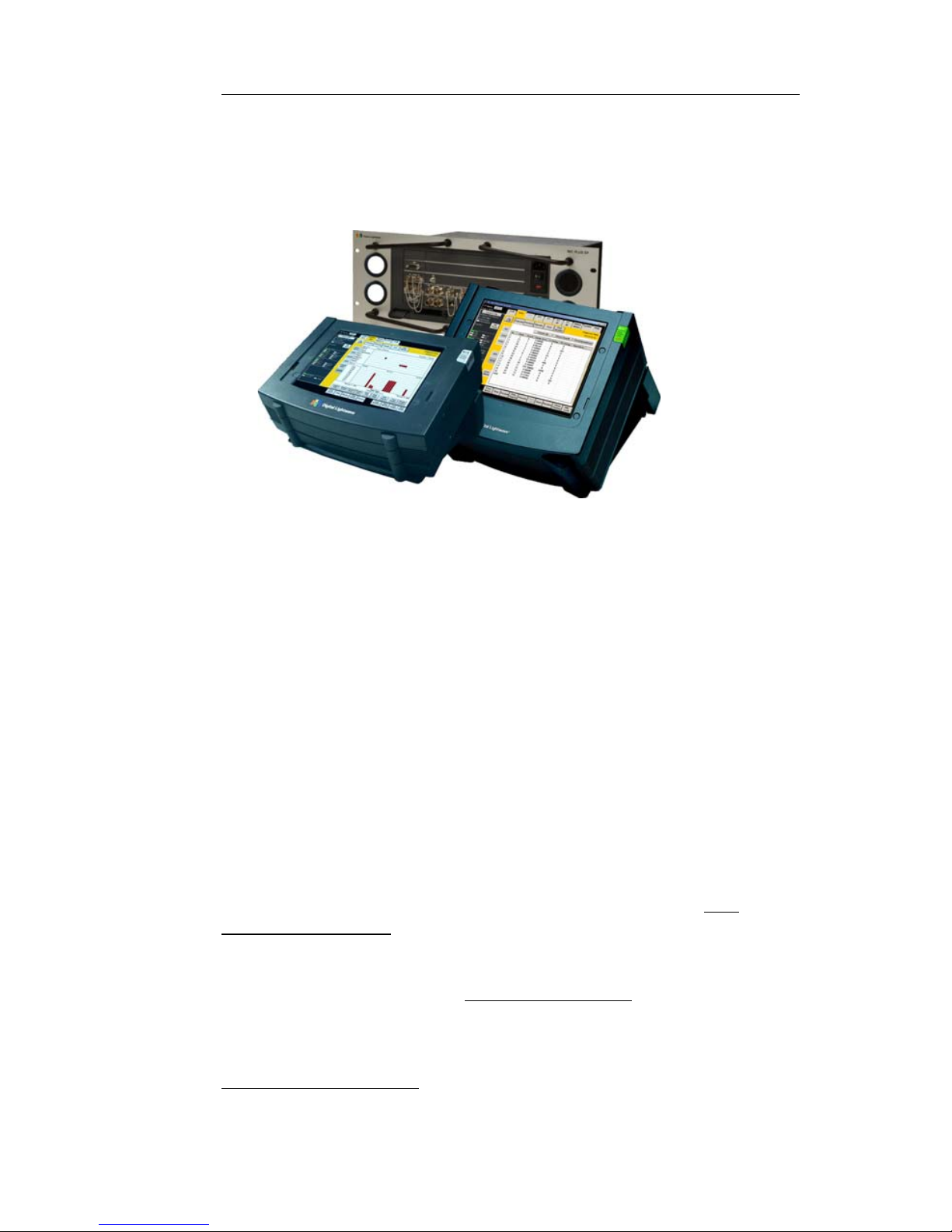
NIC
(Network Information Computer)
QUICK REFERENCE GUIDE
Document No. CO 004844K
Page 2

Document No. CO 004844K
The NIC Quick Reference Guide provides the user with the key
information necessary to start successfully testing with any Digital Lightwave NIC Platform product (NIC Plus, NIC EP, NIC
NXG, NIC BP, NIC 10G, NIC 2.5G, NIC GigE, NIC ONA, and
NIC 622M).
This document contains a number of tutorials describing the
basic operation of the NIC, including how to initiate tests and
collect test results. For detailed information about the unit’s
functions and operation, refer to the user manual, available for
download at www.lightwave.com. The user manual is also available on the CD that was included with your product, and available in the NIC unit itself by selecting the HELP tab.
Note: Images are used in this document to illustrate certain functions. Depending on the unit’s configuration, and routine product enhancements, the information on your NIC may not be the
same.
Note: Digital Lightwave, Inc. reserves the right to revise and
improve its product as it sees fit. This publication describes the
state of this product at the time of its publication and may not
represent the product at all times in the future.
Patents: The Network Information Computer (NIC) described
in this publication may be protected by one or more patents on
file with the United States Patent Office.
Trademarks: Digital Lightwave; the rectangular logo; Technology to Reach Inside the Light; Network Information Computer;
AnyBit; Anywhere, Anytime, AnyBit; NIC; Lightwave Management; NAA; Network Access Agent; Network Protocol Processor; NIC NXG, NIC 10G; NIC 2.5G; NIC Plus; NIC GigE; NIC
ONA; NIC 622M; All Path Testing and FibreVu are trademarks
or registered trademarks of Digital Lightwave, Inc. All other
brands and their products are trademarks or registered trademarks of their respective owners.
Copyright© Digital Lightwave, Inc. All rights reserved. This
publication, or parts thereof, may not be reproduced in any form,
by any method, for any purpose. For conditions of use and permission to use these materials for publication, including translation into languages other than English, contact Digital
Lightwave, Inc.
Page 3

NIC Quick Reference Guide
Table of Contents
SONET/SDH Testing Quick Start ......................................1
Ethernet Testing Quick Start ...............................................3
Fibre Channel Testing Quick Start .....................................7
OTN Testing Quick Start ..................................................11
DS1/E1/E3/DS3/E4 Testing Quick Start ..........................13
Power Information ............................................................17
NIC BP Units: ...................................................................18
The NIC Chassis ...............................................................22
Optical Interfaces ..............................................................25
Using the Touch Screen ....................................................31
Changing a protocol processor Tab Name ........................35
Touch Screen Calibration .................................................36
Understanding Test Units .................................................37
Using the Lock Icon ..........................................................38
Saving Customized Setting Configurations ......................43
Restoring a Settings Configuration ...................................44
Starting and Stopping a Test .............................................44
Pausing and Resuming a Test ...........................................49
Printing a Real-Time Test .................................................50
Printing and Saving Reports .............................................52
File Services ......................................................................57
Displaying Serial Numbers and Software Revision .........59
Entering a new License Key .............................................60
Setting Time and Date and Time Zone .............................61
External Clock In Status ...................................................64
Configuring a Protocol Mode ...........................................65
Restoring Factory Defaults ...............................................66
Configuring the Ethernet Port ...........................................66
Sending Email Alerts ........................................................68
Using Alarm Beeper Status ...............................................71
Using Chat ........................................................................73
Using the Security Features ..............................................74
Establishing a Default Login ............................................77
Contact Technical Support ................................................80
Page 4

Document No. CO 004844K
Page 5
NIC Quick Reference Guide
i
Welcome
Thank you for purchasing a Digital Lightwave NIC Platform
product for your network testing needs. You have chosen a
robust and flexible platform that will grow when your testing
needs grow.
Digital Lightwave offers a number of services to our customers
that will enable you to get the most out of your NIC Platform
product.
Hardware Upgrades: Additional modules are available for specific testing needs to support your evolving test requirements.
Test Options: Additional test capabilities can be added with
license-based Test Options. A simple license key can enable the
features in minutes with no requirement for additional hardware.
Software Upgrades: Digital Lightwave releases software
upgrades several times per year providing additional features,
improved user interface, etc. Upgrades are free during the first
year of warranty coverage.
Stay Informed: Sign up for the mailing list and receive free test
tips and product offers. Contact Digital Lightwave Support, sup[email protected] or call any Digital Lightwave location.
Find product information, application notes, user manuals, company information and more at www.lightwave.com
Technical Support: Call toll free (in the US) 1.877.929.HELP
(4357), or (outside the US) 727.475.1206 or send an email to
[email protected]
. Telephone support is available 24
hours/day, 7 days/week.
Page 6

Document No. CO 004844K
ii
Safety
The following safety precautions are provided to avoid injury
and prevent damage to this product or any products connected to
it during normal operation. Only trained and qualified maintenance personnel should perform service procedures.
Use Proper Power Cord: To avoid fire hazard, use only the
power cord provided with the instrument. For international oper-
ation, use an HO5VV-F power cord with a 1-mm
2
, two conductor plus ground, IEC 320 connector on one end, and a wallsocket plug on the other end that is certified for use in the country of installation. The entire cordset must be certified for use in
the country of installation.
Avoid Electric Overload: This unit is designed to be powered
from 100–120 and 200–240 VAC, 50–60 Hz. To avoid electric
shock, fire hazard, or damage to the instrument, do not apply a
higher or lower voltage.
Grounding: The unit is grounded through the grounding conductor of the power cord. To avoid electric shock, the grounding
conductor must be connected to earth ground. Before making
connections to the input or output terminals of the instrument,
ensure that the product is properly grounded.
Do Not Operate in Hazardous Conditions: To avoid injury or
fire hazard, do not operate this instrument in wet, damp, or other
hazardous conditions. Do not operate this instrument in an
explosive atmosphere. This instrument is not intended for outdoor use.
Eye Protection: Users should never stare into unterminated
connectors or broken fibers. In addition, fiber cables and interfaces should always be handled as if they were emitting laser
light. Always leave protective covers on optical connectors to
prevent damage and prevent laser emissions.
Field Service: This equipment is not intended to be serviced in
the field. All service is intended to be completed by Digital
Lightwave, Inc.
Page 7
NIC Quick Reference Guide
iii
Environmental Statement: This product may contain leadbased solder materials and a lithium battery for computer support. Please return all Digital Lightwave products to the factory
for proper disposal. Operation of this product is not hazardous to
the environment.
This is a class A product. In a domestic environment this product
may cause radio interference in which case the user may be
required to take adequate measures. Cables used should be less
than three meters long for compliance with EMC directive.
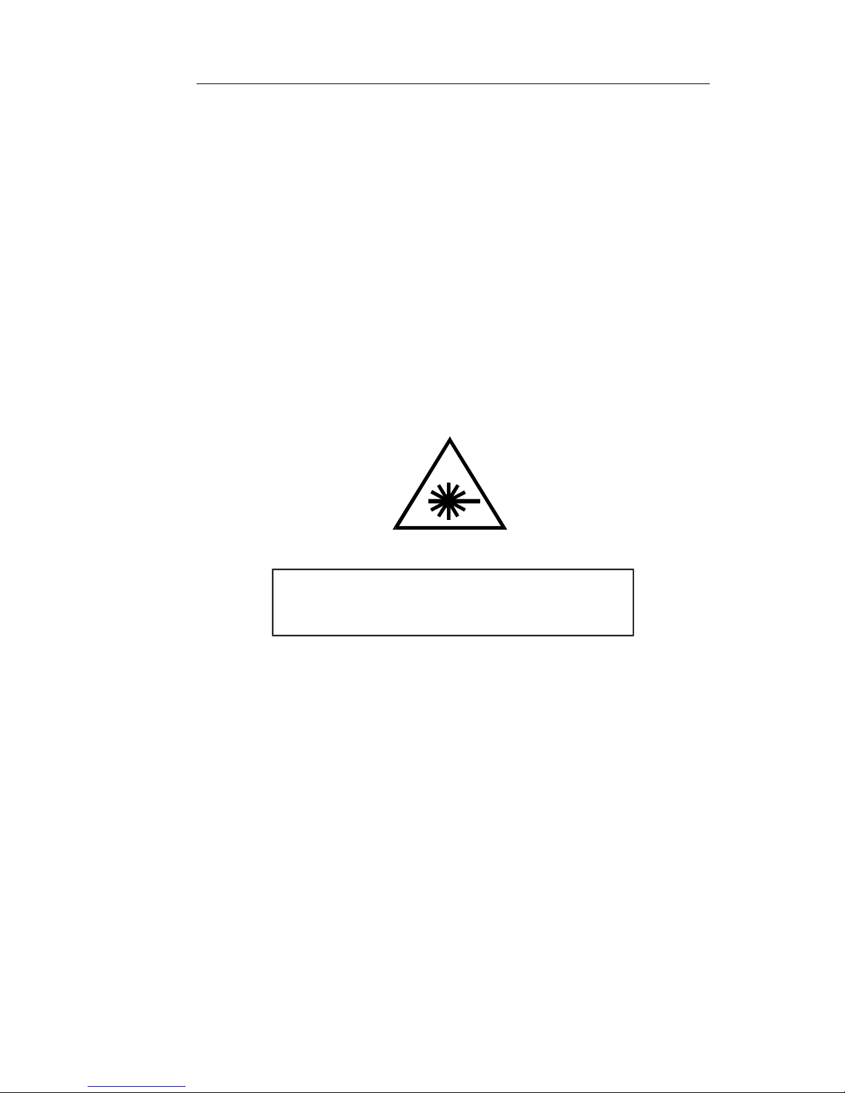
Laser Safety: The unit contains Class 1 laser devices. Never
look into an unterminated fiber. Always place dustcaps on the
optical ports when fiber is not attached to the optical ports.
CDRH Accession No. 0021615.
Use of controls or adjustments or procedures other than those
specified herein may result in hazardous radiation exposure.
NOTICE
Unterminated optical connectors may emit laser
radiation. Do not view with optical instruments.
Class 1 Laser Product
Page 8

Document No. CO 004844K
iv
Page 9
NIC Quick Reference Guide
1
SONET/SDH Testing Quick Start
The following steps outline the basic procedure for setting up a
Bit Error Rate test on a SONET or SDH interface. A number of
different modules support SONET/SDH testing (MSA, NGMR,
OMR, etc.). The basic procedure is the same for all but certain
steps, names of menu items and indications differ depending
upon which module is being used. Also, certain specialized
functions are not included in this Quick Start. For full information on test setup, see the Online Help User’s Guide.
Note: This Quick Start assumes that the test set is fully booted
up and that the device or system under test is connected.
1. Select the SONET, SDH tab at the top of the screen, or for older
module types select OC-12, STM-4, OC-48, etc.
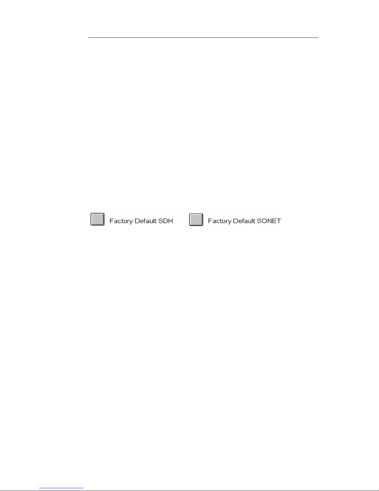
2. It is a good idea to restore the unit to factory defaults before beginning any test. Select Save/Restore, then select Restore This Test Set
and choose either of the two following options:
3. Select Transmit, then Set, then Interface and choose required interface, e.g. STM-64, OC-192, STM-16, OC-48, etc.
4. Select Mapping and choose required mapping type to match the
device or system under test.
5. Select Payload and choose required pattern.
6. Select Clock Reference and choose one of the following settings for
the transmit clock:
• Internal (OK when the unit is looped on itself, usually not
appropriate for actual testing)
• Recovered (Sets the transmit clock to match the incoming
SONET or SDH signal)
• External (Some modules will have several options including
BITS/SET, External 8KHz, External 10MHz, etc.; If external
timing is chosen, then a valid clock signal must be connected to
the appropriate clock input port on the NIC.
7. Turn on laser. The button is located in the upper left of the screen.
8. Confirm Rx power level is within the NIC’s specifications. Power
level is indicated just below the Laser is On button in the upper left
Page 10
Document No. CO 004844K
2
of the screen.
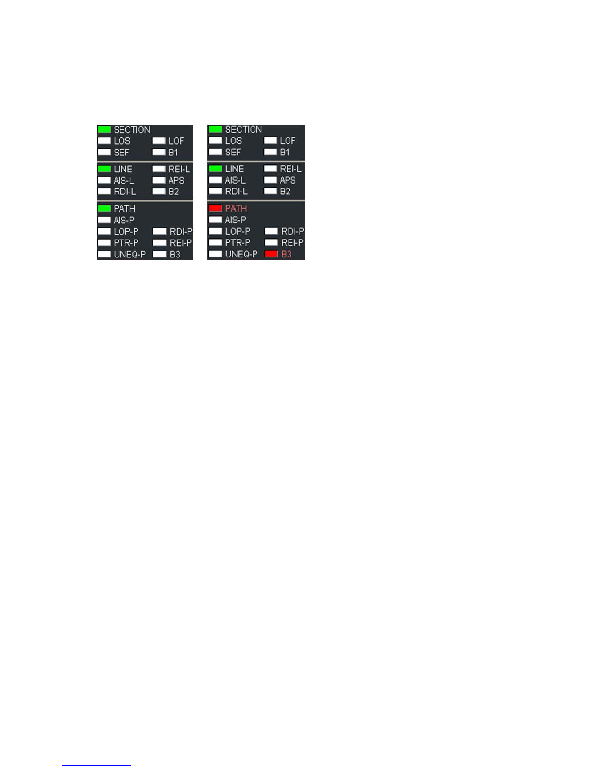
9. Confirm that no red LEDs are visible in Alarm and Status indicators.
Note that a red LED
indicates a real-time
alarm/error condition.
The red text indicates
history, that the condition has existed during
the current test.
10.Press Restart button. The NIC is now running a test.
11.Select Results and Scan. If the test is running error free, you will see
the message “No Errors or Alarms”. For error-rate, select Error. For a
listing of how many seconds each alarm has existed during the current test, select Alarm. For a chronological list of all events since the
test started, select Event Log. For a graphical representation of error,
alarm and pointer conditions, select Graphs.
12.To save or print results, see Printing/Saving Results in this Quick
Reference Guide or in the User Guide.
Page 11
NIC Quick Reference Guide
3
Ethernet Testing Quick Start
The following steps outline the basic procedure for setting up a
NIC for an Ethernet test. A number of different modules support
Ethernet testing (MSA, NGMR, High-Density Ethernet, etc.).
The basic procedure is the same for all but certain steps, names
of menu items and indications differ depending upon which
module is being used. Also, certain specialized functions are not
included in this Quick Start. For full information on test setup,
see the Online Help Users’ Guide.
NOTE
This Quick Start assumes that the test set is fully booted up
and that the device or system under test is connected.
1. It is a good idea to restore the unit to factory defaults before beginning any test. Select Save/Restore, then select Restore This Test Set
and choose either of the two following options:
2. For MSA (N61-N88, NL61-NL88) module...
NOTE
The following rates require license-based Test Options
• GigE, 10/100/1000BaseT and 100BaseFX interfaces - Select
the Dual Enet tab then Port button and choose Port 1 or Port 2.
Both ports operate simultaneously but they are set up one at a
time.
• 10G LAN - Select SONET or SDH tab, then Interface and
choose 10G LAN. Then select Packet tab.
• 10G WAN - Select SONET or SDH tab, then Interface and
choose STM-64 or OC-192. Select Mapping and choose “AU4-64c Ethernet WAN” or “STS-192c Ethernet WAN”. Then
select Packet tab.
• 11G (10G LAN over OTU-1e/OTU-2e) - Select OTN tab, then
Interface and choose OTU-1e or OTU-2e. Select Mapping and
choose 10G LAN. Then select Packet tab.
• GFP - Select SONET of SDH tab, then set Interface and Map-
ping to any configuration that is applicable to GFP. Select Payload Pattern and choose GFP. Then select Packet tab.
• ODU-0 - Select OTN tab, then Interface and choose either
OTU-1 or OTU-2. Select Mapping and choose either ODTU-
Page 12

Document No. CO 004844K
4
01, ODTU-02 or ODTU-012 as required. Select ODU-0 mapping and choose Transcoded 1000BaseX. Then select Packet
tab
3. For NGMR (N11-N49) module interface...
NOTE
The following rates require license-based Test Options
• 1G/10G LAN - Select SONET or SDH tab, then Interface and
choose 10G LAN. Then select Packet tab.
• 10G WAN - Select SONET or SDH tab, then Interface and
choose STM-64 or OC-192. Select Mapping and choose “AU4-64c Ethernet WAN” or “STS-192c Ethernet WAN”. Then
select Packet tab.
• 11G (10G LAN over OTU-1e/OTU-2e) - Select OTN tab, then
Interface and choose OTU-1e or OTU-2e. Select Mapping and
choose 10G LAN. Then select Packet tab.
• GFP - Select SONET or SDH tab, then set Interface and Map-
ping to any configuration that is applicable to GFP. Select Payload Pattern and choose GFP. Then select Packet tab.
4. For HD Ethernet (T1, T1T6) module interface...
• All rates - Select HDEnet tab, then select the Port button and
choose the required port. All ports operate simultaneously but
they are set up one at a time. Ports 1-4 are Gigabit Ethernet
optical. Ports 5-12 are 10/100/1000BaseT. Port 13 is 10Gigabit
Ethernet optical.
5. Turn Laser on in upper left of screen, if applicable.
6. Confirm Rx power level is within the NIC’s specifications. Power
level is indicated just below the Laser is On button in the upper left
of the screen.
7. Confirm that link state is green and that no red LEDs are visible in
Alarm and Status indicators. Note that a red LED indicates a realtime alarm/error condition. The red text indicates history, that the
condition has existed during the current test.
8. Select Config, then Set. Select Interface then choose required interface, if applicable.
9. Change auto-negotiation and port addresses if required.
Page 13

NIC Quick Reference Guide
5
10.Select Strms Pg 1. Select any stream within the large white area to
open the Traffic Stream Profile window. Make any change required
in stream parameters including addressing, frame length , rate,
VLAN, etc. Select Prev or Next to choose other streams. (some versions will support 32 simultaneous streams; some support 4 simultaneous streams.) Select Save All to save changes.
11.Press the Stream On/Off button once to begin transmitting on each
stream or the All button to transmit on all streams.
12.Press Restart button. The NIC is now running a test.
13.Select Results and Scan. If the test is running error free, you will see
the message “No Errors or Alarms”. For error- rate, select Error . For a
listing of how many seconds each alarm has existed during the current test, select Alarm. For a chronological list of all events since the
test started, select Event Log. For a graphical representation of error,
alarm and pointer conditions, select Graphs.
14.For individual stream statistics, select Strm Rslt.
15.To save or print results, see Printing/Saving Results in this Quick
Reference Guide or in the User Guide.
For RFC 2544 Testing:
NOTE
RFC 2544 tests must be performed on a loopback basis. In
networks that do not have routers, it may be possible to use a
simple loopback on the equipment. In networks with routers,
a second NIC in IP Reflection mode can be used as a loopback device. In IP Reflection mode, the NIC reverses MA C
and IP addresses and loops back the test packets.
1. If required, set the far-end NIC to IP Reflection mode to serve as the
loopback device. Select Config tab, press Reflect, then select DLI
Packets Only.
2. On near-end NIC, Confirm green LEDs for signal and Link State.
NOTE
Before starting RFC tests, it’s necessary to create at least one
test stream as described above.
3. Confirm that packets are being sent and received successfully on the
stream you will be using. Press stream on/off button to turn on the
Page 14

Document No. CO 004844K
6
stream that will be used for RFC2544 testing and confirm that packets are transmitted and received. While the button is in the on position, the TX and RX packet count will not be equal. This is normal. It
is only necessary to determine that packets are being successfully
received to confirm basic connectivity before beginning lengthy RFC
2544 tests.
4. Press the on/off button again to turn the stream off.
5. Press RFC Tests, then Conf.
6. Press stream Id and select the number of the stream that was configured in the earlier steps.
7. Press Trial Duration, if anything other than 60 seconds (standard, and
default) is required. For Back-to-Back Burst Testing, duration must
be 10 seconds or less.
8. To run Throu ghput Test, press ThruPut, then Start Test.
9. To run Frame Loss Test, press Frame Loss, then Start Test.
10. To run Back-to-Back Burst Test, press B2B Burst, then Start Test.
11. To save or print resu lts, see Printing/Saving Results in this Quick
Reference Guide or in the Online Help Users’ Guide.
Page 15
NIC Quick Reference Guide
7
Fibre Channel Testing Quick Start
The following steps outline the basic procedure for setting up a
NIC for a Fibre Channel test. Certain specialized functions are
not included in this Quick Start. For full information on test
setup, see the Online Help Users’ Guide.
NOTE
This Quick Start assumes that the test set is fully booted up
and that the device or system under test is connected.
1. It is a good idea to restore the unit to factory defaults before beginning any test. Select Save/Restore, then select Restore This Test Set
and choose either of the two following options:
2. Selecting data rate.
NOTE
The following rates require license-based Test Options
3. For MSA (N61-N88, NL61-NL88) module...
• 1G/2G/4G Fibre Channel - Select the Dual Enet tab then Port
button and choose Port 1 or Port 2. Both ports operate simultaneously but they are set up one at a time. Press Interface and
select 1G, 2G or 4G Fibre Channel.
• 8G/10G Fibre Channel - Select SONET or SDH tab, then Inter-
face and choose 8G or 10G Fibre Channel
4. For HD Ethernet (T1, T1T6) module interface...
• 1G/2G Fibre Channel - Select HDEnet tab, then select the Port
button and choose the required port. Fibre Channel testi ng is
available on Ports 1-4.
How to Connect to Fibre Channel SAN Switch
(without Server login)
This procedure demonstrates how to interconnect the NIC with a
Fibre Channel SAN switch. This procedure will establish a connection that does not require a Fabric and Name Server login.
1. Interconnect the transmit and receive NIC test port interfaces with
the SAN equipment. Turn Laser On in upper left of screen.
Page 16
Document No. CO 004844K
8
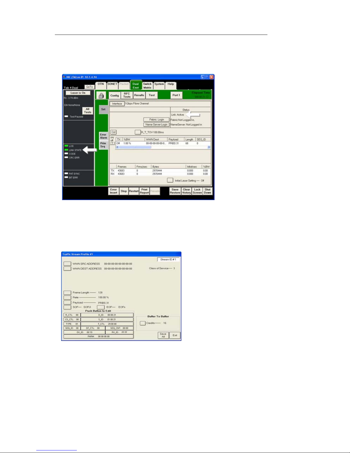
2. The NIC test port and the SAN equipment should quickly establish a
valid Link State. This will be indicated by message “Link: Active”
under the Status section in the Config/Set screen, and also the Link
State LED should be green. See Figure.
3. Select the stream to open the Traf fic Stream. The stream is in the center of the Config/Set screen. Click anywhere in the white area to the
right of the on/off button.
4. You will now see the Traffic Stream Profile dialog box. See Figure.
5. Enter the following information if required:
• Correct WWN Source and Destination addresses
• Frame Length
• Rate
• Payload test pattern
• Start of Frame (SOF)
Page 17

NIC Quick Reference Guide
9
• End of Frame (EOF)
• Buffer to Buffer Credits
6. Select “Save All” then “Exit” to save the entered test stream parameters.
7. Select the button labeled 1 to the left of the stream to turn on stream
traffic generation.
8. Fibre Channel verification statistics may now be ob served.
Fabric and Name Server Login Procedure
1. Verify the test stream Tx is set to Off before continuing. The required
Fabric and Name Server login options are not available while the test
stream is enabled.
2. Select the Fabric Login button to perform a Fabric Login. The Fabric
Login status, just to the right of the button, will display “Waiting for
Response” while it attempts to login to the SAN equipment.
3. The Fabric Login status will display “Logged In” when the process is
complete.
4. Select the Name Server Login button to perform a Name Server
Login.
5. The Name Server Login status, just to the right of the button, will dis-
play “Waiting for Response” while it attempts to login to the SAN
equipment.
6. The Name Server Login status will display “Logged In” when the
process is complete.
7. At this point the Fibre Channel test interface will have a valid Fabric
and Name Server login with the SAN equipment, and the test stream
can be enabled. Press the on/off button, labeled “1”, to the left of the
stream.
8. Fibre Chann el verification statistics may now be observed.
Analyzing Fibre Channel Test Results
1. Error and Alarm activity and other frame statistics can be viewed
using the various screens.
2. The Config/Set screen has a Count Statistics Table that displays a
summary view of transmitted and received Frame counts and Byte
counts, as well as the transmitted and received bandwidth.
Page 18

Document No. CO 004844K
10
3. The Results screens display all error and alarm counts and history, as
well as transmitted and received Frame statistics.
4. The System/All Ether Ports screen displays a summary view for all
of the Ethernet and Fiber Channel test ports in the instrument
(depending on the mode of the test ports).
5. To save or print results, see Printing/Saving Resul ts in this Quic k
Reference Guide or in the User Guide.
Page 19
NIC Quick Reference Guide
11
OTN Testing Quick Start
The following steps outline the basic procedure for setting up a
test on an OTN interface. A number of different modules support OTN testing (MSA, NGMR, OMR, etc.). The basic procedure is the same for all but certain steps, names of menu items
and indications differ depending upon which module is being
used. Also, certain specialized functions are not included in this
Quick Start. For full information on test setup, see the Online
Help User’s Guide.
Note: This Quick Start assumes that the test set is fully booted
up and that the device or system under test is connected.
1. Select the OTN tab at the top of the screen.
2. It is a good idea to restore the unit to factory defaults before beginning any test. Select Save/Restore, then select Restore This Test Set
and choose either of the two following options:
3. Select Transmit, then Set, then Interface and choose required interface, i.e. OTU-1, OTU-2, OTU-1e, OTU-2e, OTU-1f or OTU-2f.
NOTE
OTU-1e and OTU-2e carry Ethernet over OTN. OTU-1f and
OTU-2f carry Fibre Channel over OTN.
4. Select Mapping and choose required mapping type to match the
device or system under test.
5. Select Payload and choose required pattern.
6. Select Clock Reference and choose one of the following settings for
the transmit clock:
• Internal (OK when the unit is looped on itself, usually not
appropriate for actual testing)
• Recovered (Sets the transmit clock to match the incoming OTN
optical signal)
• External (Some modules will have several options including
BITS/SET, External 8KHz, External 10MHz, etc.; If external
timing is chosen, then a valid clock signal must be connected to
the appropriate clock input port on the NIC.
7. Turn on laser. The button is located in the upper left of the screen.
Page 20
Document No. CO 004844K
12
8. Confirm Rx power level is within the NIC’s specifications. Power
level is indicated just below the Laser is On button in the upper left
of the screen.
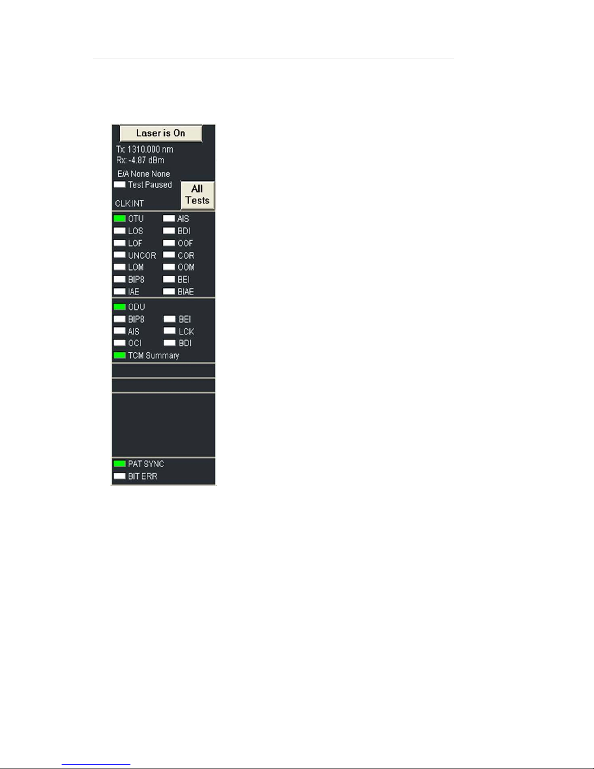
9.Confirm that no red LEDs are visible in
Alarm and Status indicators.
Note that a red LED indicates a real-time
alarm/error condition. The red text indicates
history, that the condition had existed during
the current test.
10.Press Restart button. The NIC is now running a test.
11.Select Results and Scan. If the test is running error free, you will see
the message “No Errors or Alarms”. For error-rate, select Error. For a
listing of how many seconds each alarm has existed during the current test, select Alarm. For a chronological list of all events since the
test started, select Event Log. For a graphical representation of error,
alarm and pointer conditions, select Graphs.
12.To save or print results, see Printing/Saving Results in this Quick
Reference Guide or in the User Guide.
Page 21
NIC Quick Reference Guide
13
DS1/E1/E3/DS3/E4 Testing Quick Start
The following steps outline the basic procedure for setting up a
Bit Error Rate test on PDH/T-Carrier interfaces at any of the following rates:
• DS1 (1.544Mbps)
• E1 (2.048Mbps)
• E3 (34Mbps)
• DS3 (45Mbps)
• E4 (139Mbps)
This Quick Start guide does not include all testing functions
available. For full information on test setup, see the Online Help
User’s Guide.
Note: This Quick Start assumes that the test set is fully booted
up and that the device or system under test is connected.
1. Select the required rate at the top of the screen.
2. It is a good idea to restore the unit to factory defaults before beginning any test. Select Save/Restore, then select Restore This Test Set
and choose either of the two following options:
Selecting Interface Type
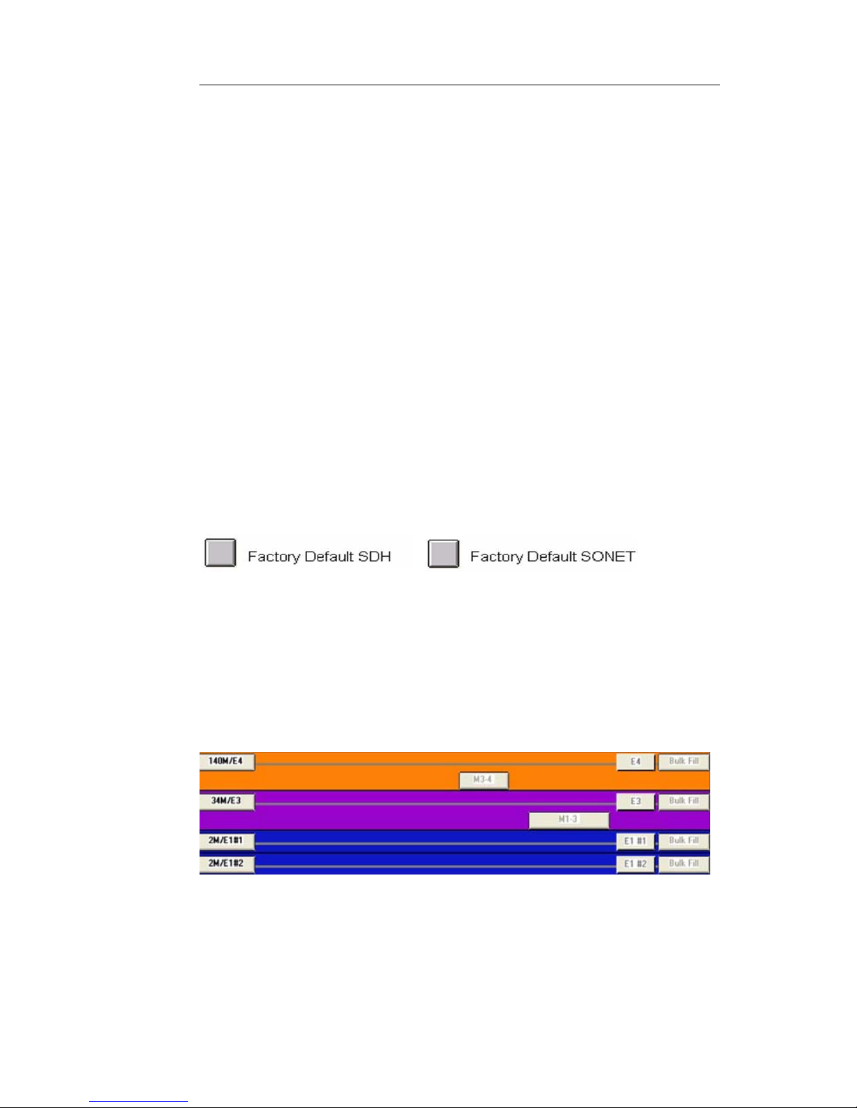
There are essentially two different ways to set up a PDH/T-Carrier test, either directly through a DS1, E1, E3, DS3 or E4 interface, or drop/insert to/from a SONET/SDH or OTN rate. The
two different types can be most easily seen by selecting Switch
Matrix at the top of the screen. The following is an example of
direct connection at the PDH/T-Carrier rates. See figure.
3.
The left side of the screen represents the physical interfaces. The
right side of the screen is mapping down to the pattern generators and receivers.
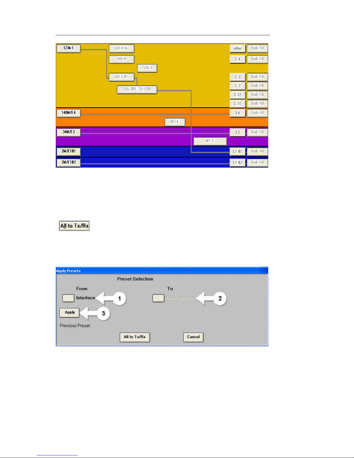
The following is an example of a drop/insert configuration, with
STM-1 physical interface mapped down to E1. See figure.
Page 22
Document No. CO 004844K
14
4. T o set all PDH/T-Carrier rates for direction connection, select the All
to TX/RX button. This button can be found at the bottom of the
Switch Matrix or in any PDH/T -Carrier tab by selecting Presets at the
bottom of the screen. See figure.
5. To set up drop/insert configuration, select Presets at the bottom of
any PDH/T-Carrier tab, then follow these steps. See figure.
a. Select Interface and select the physical interface (e.g. OC-
48, STM-4, etc.)
b. Select Con fig uration. This is the PDH/T-Carrier rate to
which you would like to drop/insert (e.g. DS1#1, DS1#2,
E1, etc.). Note that the LI (Line Interface) menu items will
drop/insert to the external port.
Page 23

NIC Quick Reference Guide
15
c. Select Apply.
4. Select Transmit, then Set1.
5. Select Settings Control and choose either Coupled, so that all
changes made on Transmit are duplicated on Receive, or Independent if it’s require to have Transmit and Receive are to be configured
differently.
6. Select and change Framing, Mapping and Payload Pattern as
required.
7. Select Clock Reference and choose one of the following settings for
the transmit clock:
• Internal (OK when the unit is looped on itself, usually not
appropriate for actual testing)
• Recovered (Sets the transmit clock to match the incoming sig-
nal)
• BITS/SET (External) If this option is chosen, a valid clock sig-
nal must be connected to the appropriate clock input port.
8. Select Error/Alarm button on the left if required to send intentional
errors. Choose error type then press the Error Insert button at the bottom of the screen.
9. Confirm that no red LEDs are visible in Alarm and Status indicators.
Note that a red LED indicates a real-time
alarm/error condition. The red text indicates
history, that the condition has existed during
the current test.
10. Press Restart button. The NIC is now running a test.
11. Select Results and Scan. If the test is running error free, you will
Page 24

Document No. CO 004844K
16
see the message “No Errors or Alarms”. For error-rate, select Error .
For a listing of how many seconds each alarm has existed during
the current test, select Alarm. For a chronological list of all events
since the test started, select Event Log. For a graphical representation of error, alarm and pointer conditions, select Graphs.
12. To save or print results, see Printing/Saving Results in this Quick
Reference Guide or in the User Guide.
Page 25

NIC Quick Reference Guide
17
Power Information
NIC Platform products are AC powered. The NIC BP (Battery
Power) chassis includes a battery for backup purposes. Adhere
to the following safety notices for all NIC units. The NIC BP has
specific issues and requirements. See the section entitled “NIC
BP Units”.
Safety Notices:
Use Proper Power Cord: To avoid fire hazard, use only the
power cord provided with the instrument or, for international
applications, use an HO5VV-F power cord with a 1-mm
2
, two
conductor plus ground, IEC 320 connector on one end, and a
wall-socket plug on the other end that is certified for use in the
country of installation. The entire cordset must be certified for
use in the country of installation.
Avoid Electric Overload: This unit is designed to be powered from 100–120 and 200–240 VAC, 50–60 Hz. To avoid
electric shock, fire hazard, or damage to the instrument, do not
apply a higher or lower voltage.
Grounding: The unit is grounded through the grounding conductor of the power cord. To avoid electric shock, the grounding conductor must be connected to earth ground. Before
making connections to the input or output terminals of the
instrument, ensure that the product is properly grounded.
Power Entry Module
Page 26
Document No. CO 004844K
18
NIC BP Units:
General Information
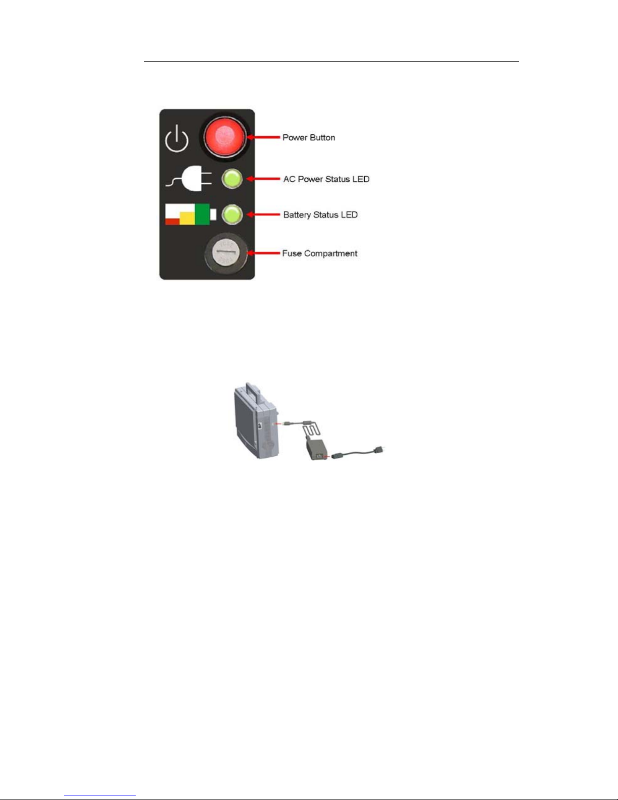
• Two-slot portab le NIC chassis with battery backup - supports
uninterrupted testing when AC power is interrupted
• Battery run time varies depending on the unit's configuration
and amount of battery charge
• Real-time battery status information is provided on the User
Interface, with LED indicators on the faceplate, and with SCPI
• The battery pack is located on the back side of the NIC BP
chassis, and is field replaceable
• When an external AC power supply is connected to the unit, the
battery can be disconnected and exchanged without having to
turn off the unit
• NIC BP units come with standard three (3) year limited war-
ranty
• NIC BP battery packs come with one (1) year limited warranty
• Additional batteries, AC power supplies, and external battery
charging bays can be purchased from Digital Lightwave
Page 27
NIC Quick Reference Guide
19
NIC BP Power Module
Recharging the Battery
• An external AC power supply is provided with every NIC BP
unit, along with a standard power cable
• Use only the external AC power supply provided by Digital
Lightwave with the NIC BP
• For international use, a power cable applicable to that country
can be substituted; use an HO5VV-F power cord with a 1-mm
2
,
two conductor plus ground, IEC 320 connector on one end, and
a wall-socket plug on the other end that is certified for use in
the country of installation. The entire cordset must be certified
for use in the country of installation.
• The NIC BP's power entry connector is located on the upper
right-hand side of the NIC BP chassis
• The AC Power Status LED on the faceplate will illuminate
green, and the battery will recharge whether the NIC BP is on
or off
• Battery charge time (unit on): 2-6 hrs. depending on configura-
tion
Page 28
Document No. CO 004844K
20
• Battery charge time (unit off): approximately 2 hrs.
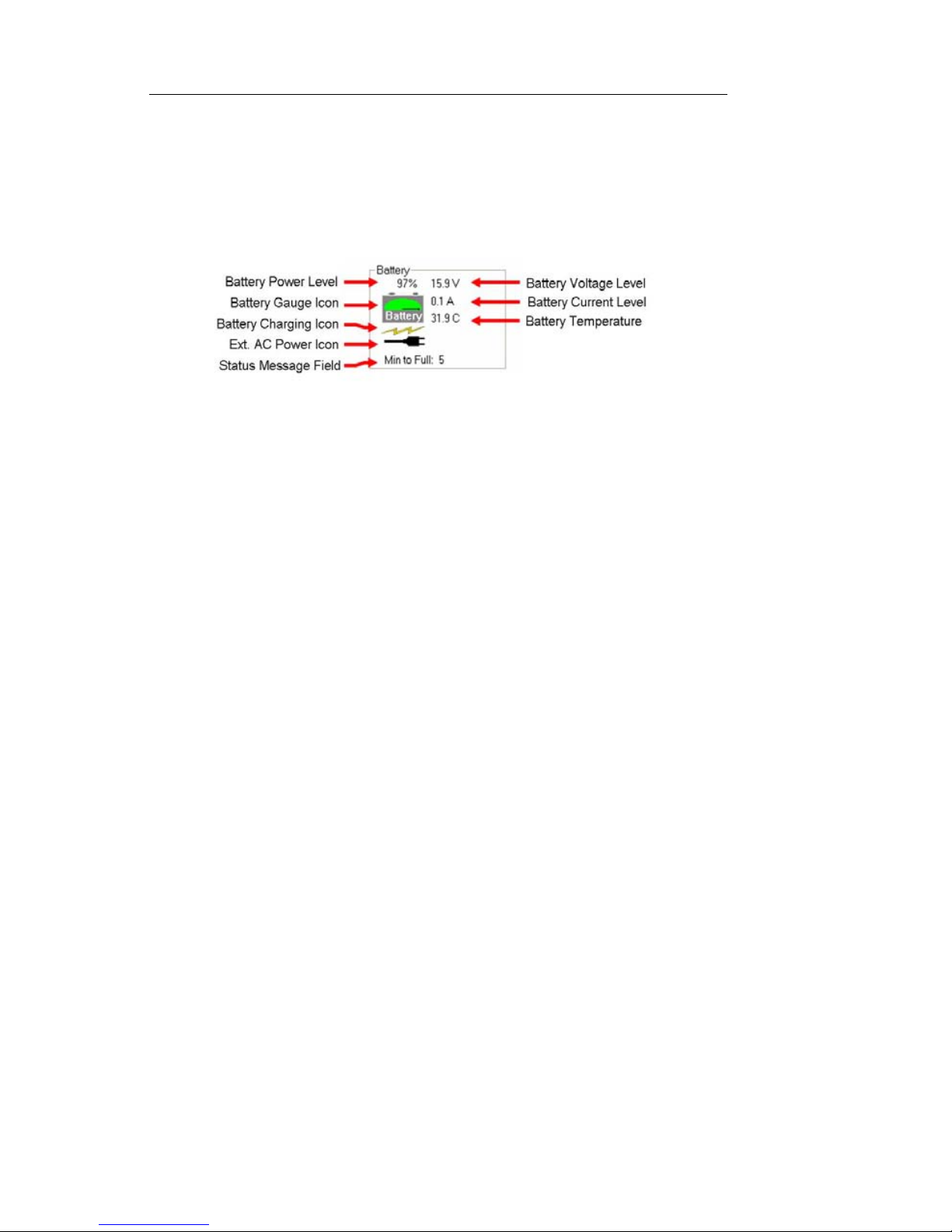
Battery Status Indicator
To view the Battery Status Indicator, select the System tab then
MISC. The following information is displayed:
Long-Term Battery Storage
If the NIC BP’s Lithium-Ion battery is stored for long periods of
time, certain precautions should be taken to protect it from damage. Improper storage will reduce the battery’s life and may
even render the battery unusable.
• The battery should be stored in a partially charged state,
approximately 65% of capacity.
–Charge status can be determined by viewing the Bat-
tery Status Indicator in the NIC GUI under System/
MISC.
–The battery itself, removed from the NIC, also has a
charge indicator with four LEDs (25%, 50%, 75%,
100%). Press the button and confirm that only the 25%
and 50% LEDs are illuminated.
• In long-term storage the battery will continually lose its charge.
The charge level should be verified every 3-4 weeks with either
of the two methods described above.
• Store the battery in a cool environment but not below freezing.
In general, the colder the temperature the slower the charge
level decreases.
• If the battery is stored in an uncharged state for a long period of
time, it may become unusable.
Turning the NIC On
1. Connect the proper power cord to the AC power cord connector in
the unit’s connector panel and then plug into an AC power source.
Page 29

NIC Quick Reference Guide
21
2. Press the power switch to the On (1) position or for NIC BP, press
the red power button.
3. When the Graphical User Interface appears, the NIC BP unit is
ready for use.
Turning Off or Rebooting the NIC
IMPORTANT
It is important to use the procedure described below when shutting
down the NIC. Failure to do so may result in lost data and corrupt
system files.
NOTE
The shutdown procedure can only be performed through the graphical
user interface.
1. From any protocol processor tab, select the Shut Down button at
the lower right of the screen. A dialog box will appear.
• To shut down the NIC, select Shutd own.
• To restart the NIC, select Reboot.
2. Select Ok from the next dialog box.
3. When the screen has gone black, turn off the power switch or
unplug the unit.
Page 30
Document No. CO 004844K
22
The NIC Chassis
The NIC Platform is a scalable solution for your testing needs,
today and into the future. As technology evolves and your needs
change, you will be able to add software or hardware options to
the NIC.
Your NIC may offer a variety of available Test Options, licensebased features that can be enabled in minutes with only a license
key.
If hardware upgrade is required, modules can be upgraded or
replaced to support additional features. Modules are not field
replaceable.
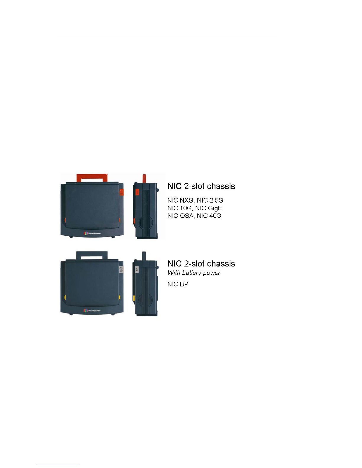
2-Slot NIC Chassis
The NIC 2-slot chassis, with or without battery power, is the
most portable NIC solution. In its cloth case it can fit under an
airline seat and is very easy to carry at less than 14 pounds.
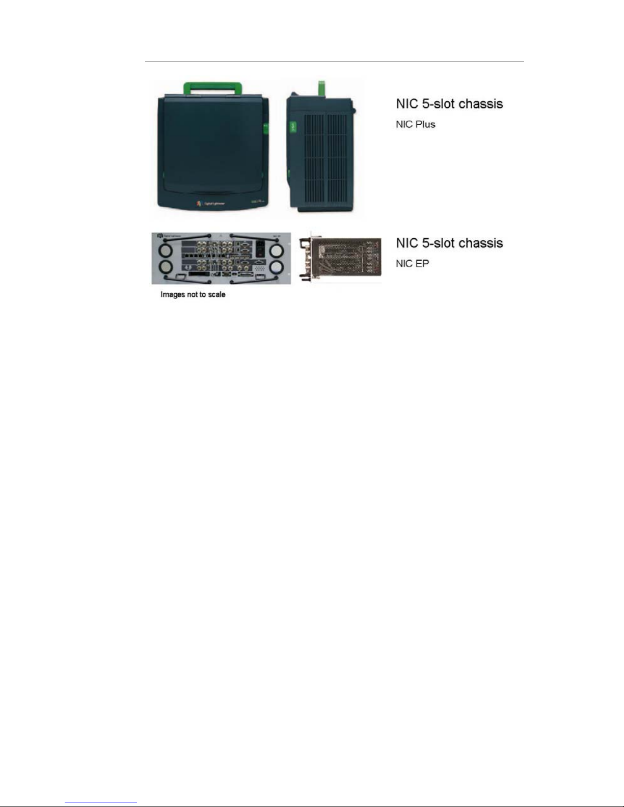
5-Slot NIC Chassis
Page 31
NIC Quick Reference Guide
23
The larger NIC Plus and NIC EP chassis can support up to 5
modules with multiple-simultaneous testing. The 5-sl ot chassis
solution offers the most opportunities for upgrade to additional
features. The NIC Plus and NIC EP are identical in functionality
except for the packaging and absence of touchscreen in the NIC
EP (Embedded Platform). The NIC EP has no built-in GUI but is
controlled by our remote management software, included at no
additional charge with all NICs.
A hard carrying case with wheels is available for the NIC Plus.
Page 32
Document No. CO 004844K
24
Care and Transport
The plastic case of NIC products are very rugged and designed
to protect the inner structure and circuitry of the instrument. No
routine maintenance is required.
Cleaning
NOTE
The NIC is not a water-tight device. The circuitry can be
damaged if liquid is allowed to seep insi de the instrument. Do
not allow any liquid to pool at the bottom of the touch screen.
1. Clean the plastic case with a soft lint-free cloth such as Kim Wi pes,
manufactured by Kimberly Clark Corporation (part number 34256).
2. When necessary the plastic case can be cleaned with isopropyl alcohol, clean water, or a mild cleaner such as Plast-n-Glass, manufactured by the Chemtronics Corporation (part number ES1668).
Damage Prevention
• Locate the unit where it will not be damaged by falling or mov-
ing objects.
• Do not place the unit in a place where it could fall more than 12
inches.
• Do not use any abrasive material or harsh chemicals on the
plastic case.
• Do not immerse the NIC in water.
• Always carry the NIC in its cloth case or in an approved ship-
ping container.
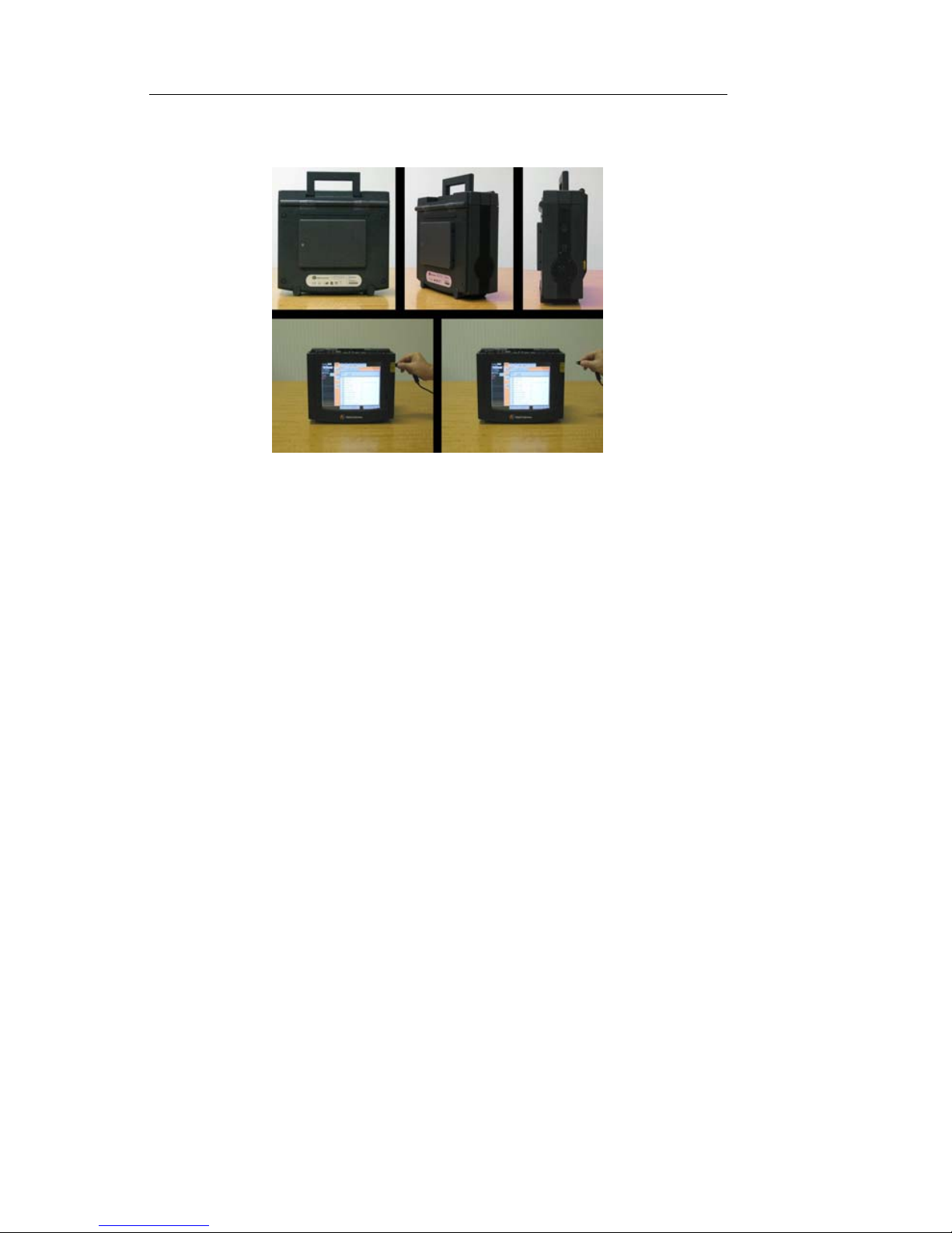
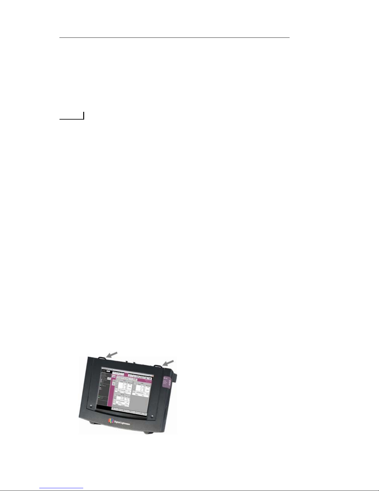
• Never pick up or hang up a NIC by the top cover latches. See
figure.
Page 33
NIC Quick Reference Guide
25
Optical Interfaces
For reliable operation and testing, optical fiber interfaces must
be clean and in good condition. This section provides information on cleaning and proper care of fiber optic interfaces, cables
and modules.
WARNING
Never, under any circumstances, look into an unterminated fiber.
Pluggable Optics Modules
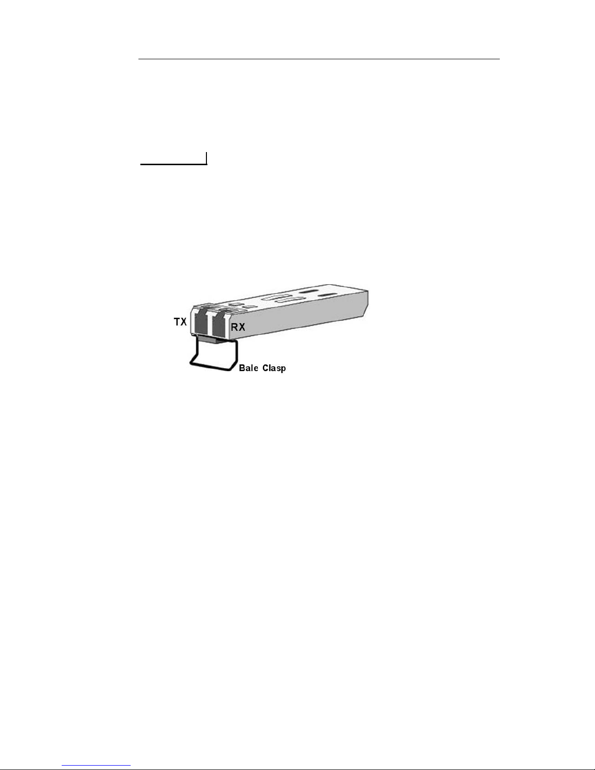
Some NIC modules utilize pluggable SFP/XFP optical transceiver modules. See figure.
Use only the modules supplied with the NIC product. Replacements or additional modules can be obtained through Digital
Lightwave sales.
SFPs and XFPs are hot-swappable. They can be removed or
inserted while the NIC is running. The modules are fragile and
are static sensitive. Observe the following precautions when
handling the pluggable modules:
• Always keep dust covers in place when fiber patch cords are
not connected.
• Observe standard precautions to prevent electrostatic discharge.
• Store and transport modules only in anti-static packaging.
• Take care not to drop an optical module.
• Protect optical modules from exposure to liquid. If cleaning is
required, utilize only dry, lint-free cloth and swabs.
To remove an SFP or XFP:
• Open the bale clasp with your index finger (If the bale clasp is
obstructed and you cannot use your index finger to open it, use
a small flat-blade screwdriver to open the bale clasp.)
Page 34

Document No. CO 004844K
26
• Grasp the SFP module between your thumb and index finger
and carefully remove it from the port.
To install an SFP or XFP:
• Carefully line up the module and fully insert it into the port.
• Close the bale clasp.
Importance of Attenuation
Optical receivers are specified to operate only within a certain
range of optical power. Signals that are too low in power can
result in a Loss of Signal indication or in bit errors. Signals that
are two strong can likewise result in bit errors but may also
result in permanent damage to the receiver.
When looping the unit on itself, or when connecting any signal
to the RX port, confirm with an optical power meter that the
optical power is within the specified range for the optical transceiver you are using. If a signal is too strong, use an optical
attenuator to bring the power level into the specified range.
Optical receivers which are damaged or destroyed by high-powered optical signals are not covered under warranty. Repair costs
can be several thousand dollars.
Single-Mode/Multi-Mode Fiber
Single-mode (SM) fiber has a very small light-carrying core,
allowing the light to travel only one path or “mode”. Multi-mode
(MM) fiber has a relatively large core and the light is allow to
travel multiple paths or “modes” through the fiber. SM fiber is
used for longer distance transmission with laser-diode-based
transmitters. MM fiber is normally used for shorter distance
applications with LED-based transmitters.
The NIC Platform supports both SM and MM optical transceivers. It is important to use the correct fiber for your application. In
general, 1310nm and 1550nm optical modules are usually SM
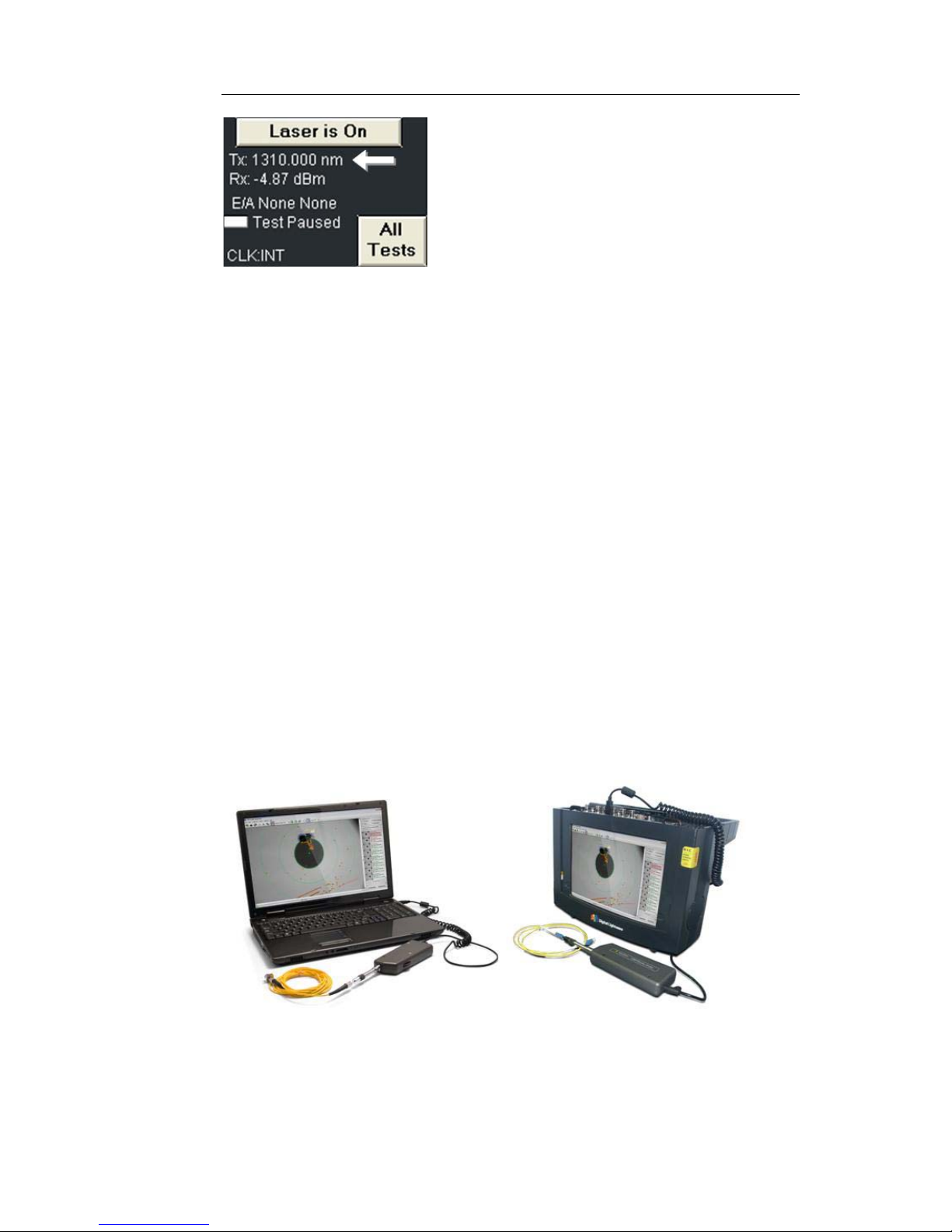
and 850nm optical modules are usually MM. The TX wavelength is displayed on the GUI just below the Laser on/off button. See figure.
Page 35
NIC Quick Reference Guide
27
With pluggable optical modules, the wavelength and sometimes
whether they are SM or MM is printed on the module itself. If
there is a doubt, look up the part number on the manufacturer’s
website. SM patch cords are usually yellow and MM patch cords
are usually orange for easy identification.
Fiber Inspection and Cleaning
For reliable operation and for consistent test results, it is very
important to have clean and undamaged fiber connectors. Oils,
airborne particles of dust, lint, dirt and other debris, if not
removed, can scratch and damage fiber-optic connectors and
jeopardize the integrity and accuracy of the optical signal. The
ferrule end-faces of fiber-optic patch cords and receptacle connectors are some of the most critical components for fiber-optic
networks. BEFORE inserting any patch cord into the test equipment or any network equipment, clean and inspect both the
patch cord and the bulkhead.
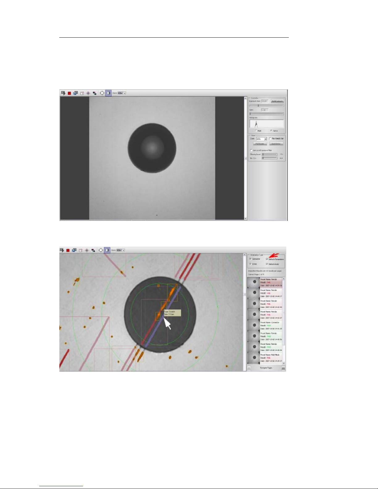
Inspection can be performed wi th the Digital Lightwave USB
FibreVu Probe. See figure.
This device can be connected to either PC or NIC Platform product and can be used to inspect both patch cords (male) fiber connectors or bulkheads (female) with up to 1500x magnification.
Page 36
Document No. CO 004844K
28
Adapters are available for all common interface types. Available
PC software enables automated pass/fail testing.
This is an example of a clean fiber end face in good condition:
The following is an example of a fiber end face with unacceptable contamination and scratches:
To inspect and clean fiber patch cords, use the following procedure:
1. Verify that no optical power is present on the fiber. An active optical
signal may make it impossible to see the image of the fiber end face
and a strong signal may damage the USB FibreVu Probe’s camera.
Page 37

NIC Quick Reference Guide
29
2. Connect the patch cord to USB FibreV u Probe and select Start Video.
Confirm the image of the fiber end face is visible. Adjust the focus as
required.
3. Optional. Select Perform Test to run the automated inspection with
pass fail criteria.
4. If the end-face is acceptable, inspect and clean the receptacle with the
procedure below, then use the fiber optic patch cord as intended.
5. If the end-face is not acceptable, clean the connector, then re-inspect.
See the following steps for a suggested procedure.
6. Using the pressurized canned air, blow away any dust particles that
may be on the exterior surface of the connector, particularly the sides
and end-face of the ferrule. Hold the can approximately 2 inches
from the surface to be cleaned and apply 3-5 short blasts of air.
7. Clean the surface of the fiber ferrule with any commercially available method, such as a CLETOP device, lint-free cloth or the AFL
One-Click Cleaner. See figure.
NOTE: The AFL One-Click Cleaner can be
used to clean patch cord end faces (male) and
bulkhead connectors (female).
AFL and One-Click Cleaner are trademarks
or service marks of AFL Corporation, a subsidiary of Fujikura Ltd. of Japan.
8. Alcohol may be required to loosen or dissolve deposits. Take care to
remove all liquid with compressed air and cleaning device.
9. If the end-face is damaged or scratched beyond cleaning or repair,
replace the connector.
10.Re-inspect the fiber end face.
To inspect and clean fiber bulkheads, use the following procedure:
1. Verify that no optical power is present on the connector. An active
optical signal may make it impossible to see the image of the fiber
Page 38

Document No. CO 004844K
30
end face and a strong signal may damage the USB FibreVu Probe’s
camera.
2. Insert the USB FibreVu Probe into the receptacle and select Start
Video. Confirm the image of the fiber end face is visible. Adjust the
focus as required.
3. Optional. Select Perform Test to run the automated inspection with
pass fail criteria.
4. If the end-face is acceptable, and the fiber patch cord you are using
has also been cleaned and inspected, use the fiber optic patch cord as
intended.
5. If the end-face is not acceptable, clean the connector, then re-inspect.
See the following steps for a suggested procedure.
6. Using the pressurized canned air, blow away any dust particles that
may be on the surface of the connector. Hold the can approximately 2
inches from the surface to be cleaned and apply 3-5 short blasts of
air. If practical, hold the bulkhead facing down so that dust and other
particles can fall out rather than settle again on the surface.
7. Clean the surface of the fiber ferrule with lint-free swab or the AFL
One-Click Cleaner.
8. Alcohol may be required to loosen or dissolve deposits. Take care to
remove all liquid with compressed air and cleaning device.
9. If the end-face is damaged or scratched beyond cleaning or repair,
replace the connector.
10.Re-inspect the fiber end face.
Page 39
NIC Quick Reference Guide
31
Using the Touch Screen
To use the touch screen, place your finger directly onto the screen to
select tabs and buttons associated with a specific function.
NOTE
A blunt pointing device such as a stylus can also be used to select touch
screen functions. However, avoid using sharp instruments, such as pen
tips, pencil tips, keys, and paper clips. These objects may scratch and
mark the touch screen.
The use of a USB mouse is also permitted to move the cursor and
objects on the screen can be selected by the left (or default) mouse button.
Touch Screen Components
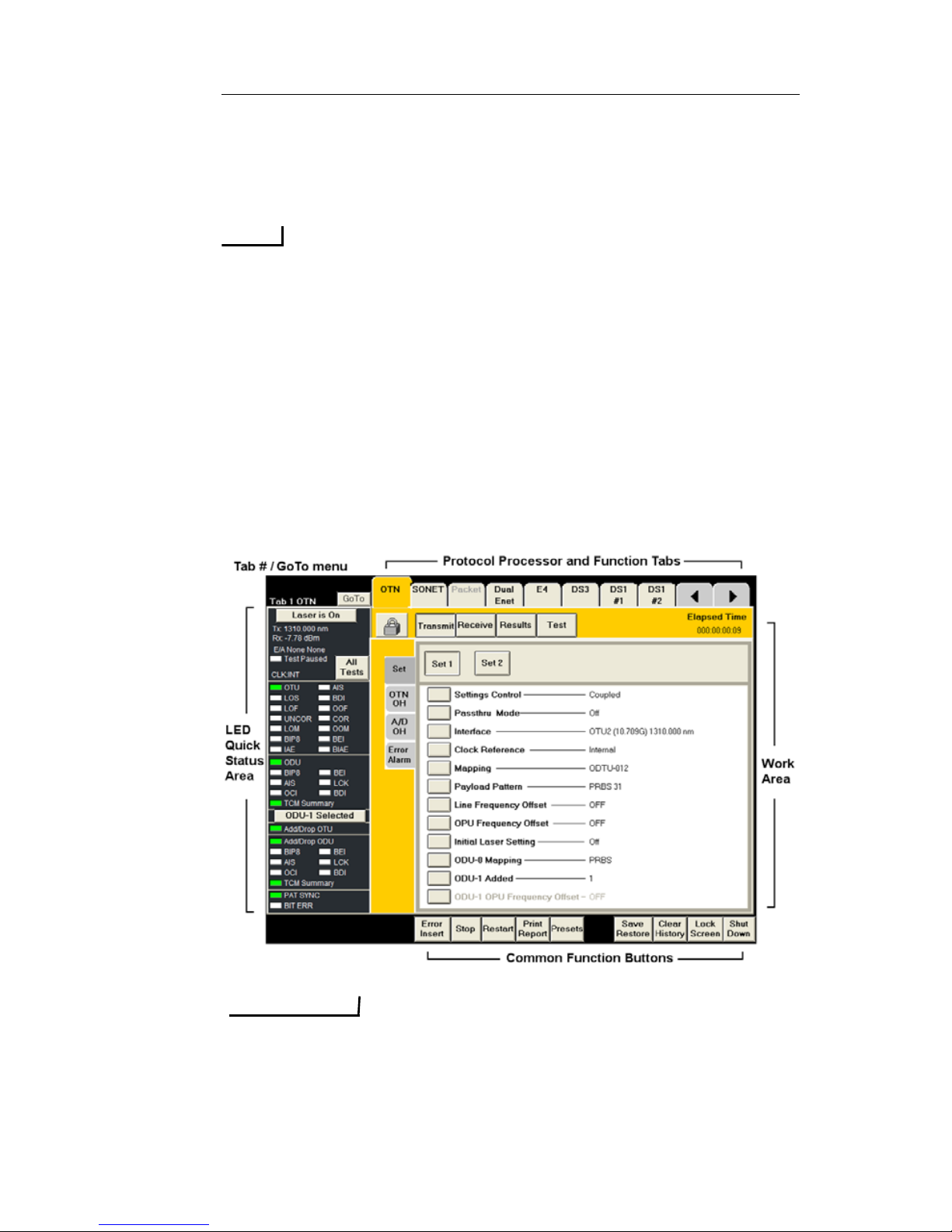
The touch screen is the user interface to the unit. The following is an
example of the NIC Plus Graphical User Interface (GUI).
IMPORTANT
The illustrations that appear in this document are used as examples to assist
you through a procedure. Because of product enhancements, these images
may not show all items that appear on your touch screen.
Page 40
Document No. CO 004844K
32
Work Area
This area consumes the majority of the unit’s touch screen. All NIC
functions are displayed in the form of a tab. Using these tabs, you can
view incoming error and alarm statistics, and configure the unit for
operation.
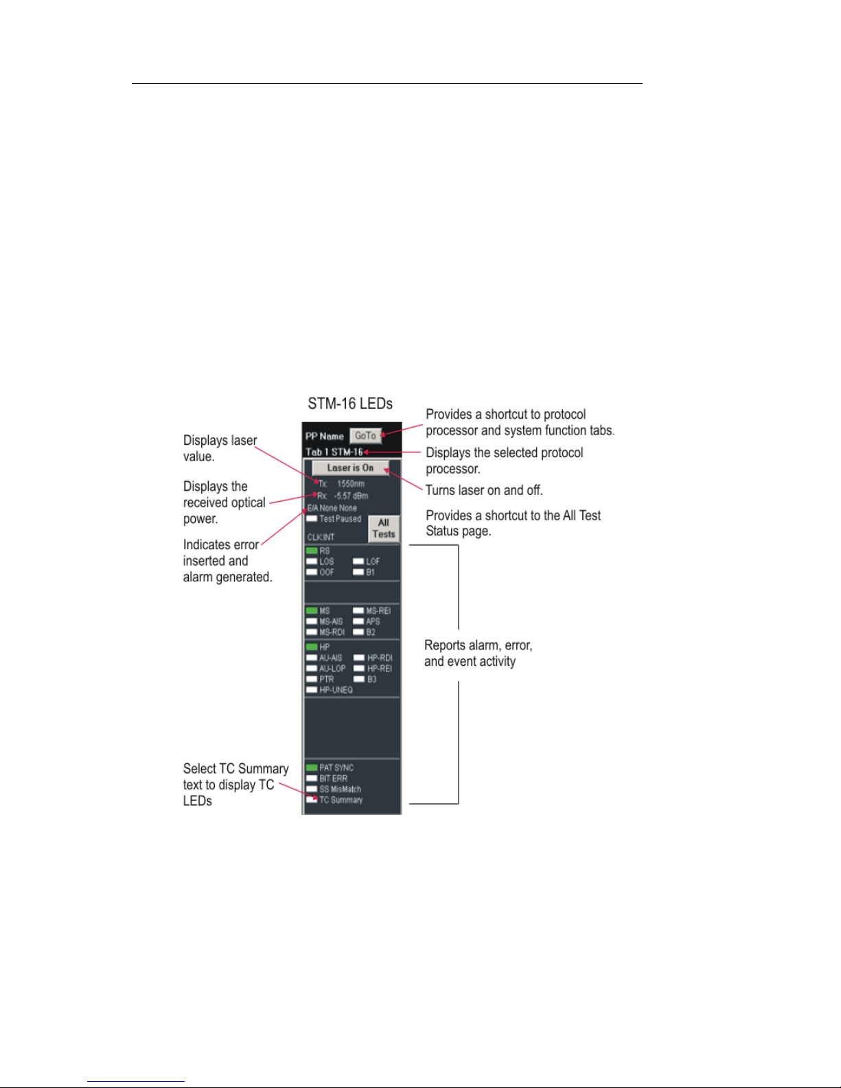
LEDs/Quick Status Area
The left side of the touch screen provides an at-a-glance view of the
selected protocol processor’s LEDs and Laser ON/Off button. The
LEDs report incoming error and alarm activity, current status, and event
history.
Using LEDs
The unit uses LEDs to report alarm, error, and event activity. These
visual cues help to narrow the focus if problems are detected on the
incoming signal and provide a starting point for problem diagnosis.
Page 41

NIC Quick Reference Guide
33
The following describes what is indicated by the LED color:
LED/Quick Status Area Color Description
Common Function Buttons
The bottom of the touch screen contains task-oriented buttons that
appear on the screen in protocol processor or Switch Matrix mode.
These buttons do not appear when using the System or Help tabs. Additionally, buttons that do not pertain to the selected protocol will not
appear when that protocol screen is displayed.
The common function buttons include:
• Error Insert: Allows a single error to be inserted into the
transmit data stream. The type of error and insertion rate are
determined using the Error to Insert and Error Insert Rate
functions, which are accessed by selecting a protocol’s Transmit tab followed by the Error Alarm tab.
•Stop: Stops the reporting of received data and takes a snapshot
of error, alarm, and event activity.
• Restart: Clears and resets error, alarm, and event activity coun-
ters, statistics, and LEDs for the specific protocol processor. It
also starts any activity that was stopped using the Stop button.
• Print Report: Opens the Report Setup menu which lists a vari-
ety of Report types that can be Printed or Saved to file. Report
types available are Statistics which includes error and alarm
results and other test statistics, Settings which includes the tests
current function settings, an Event Log report, Screen Capture,
and many more. See the Users Manual for more details.
If the LED is... Then this indicates...
Green with white
text
Normal operation. The LED is used as a status
indicator.
White with white
text
Normal operation, no errors or alarms. The LED
is used as an error/alarm indicator.
Red with red text An error or alarm event is in progress. The LED
is used as an error/alarm indicator.
White with red
text
An error or alarm event was detected, but is now
cleared. The text serves as a history indicator.
Page 42

Document No. CO 004844K
34
•Presets: Selects automatic mappings and configurations
(known as presets) that quickly and conveniently sets up the
system for operation by adding and dropping signals. Using
Presets involves selecting a starting protocol and its interface,
and then making an internal connection to multiplex with
another protocol or mapping.
• Auto Conf: (Only available on specific protocols). Detects var-
ious parameters about the incoming signal, such as signal rate,
mapping, and payload pattern, and configures the unit accordingly.
• Save/Restore: Provide two options Save This Test Set and
Restore This Test Set.
•Save This Test Set: Saves a customized configuration for all
protocol processor Transmit or Receive settings.
• Restore This Test Set: Allows the user to swit ch the Protocol
mode between SONET and SDH, or DS3/DS1 and E3/E1. This
menu also allows users to Restore Factory Default, which not
only changes the Protocol mode but also forces all TX and RX
settings (including Overhead bytes, Test Stream s, Add/Drops,
Etc.) back to their original factory default configurations. This
menu also allows users to recall any user-saved settings configuration file for all the processors on the selected Test Unit.
• Clear History: Resets all LEDs and Status Indicators (the LED
text).
• Lock Screen: Disables the unit’s touch screen. To lock and
unlock the screen, you must enter a User ID and Password.
• Any User ID with Admin permissions can also be used to
unlock the touch screen.
• Locking the touch screen on one GUI session does not have
any affect other Remote GUI sessions.
• Shut Down: Provides access to Shutdown or Reboot the NIC
unit’ s operating system. After the operating system has successfully shut down the screen will turn black, and the power switch
can safely be turned to the Off position.
Protocol Processor and Function Tabs
The first set of tabs are located at the top of the touch screen and remain
static on the screen regardless of which tab is selected.
Page 43

NIC Quick Reference Guide
35
These tabs allow you to easily navigate and switch between functions.
When a function tab is selected, the information displayed on the screen
will change and correspond to that particular function. Additionally, the
Back and Forward arrows allow you to scroll through various tabs.
This function is similar to the Go To button that appears in the LEDs/
Quick Status area.
The specific protocol processor tabs in each NIC unit will vary depending on each units unique hardware configuration as well as licensed test
options.
The last three tabs on the right are always the same for every NIC unit:
•Switch Matrix: Displays and allows you to configure the
OTN, SONET/SDH and PDH Interface rates and Mappings,
and Add/Drop connections between the OTN, SONET/SDH
and PDH protocol processors.
•System: Sets unit and user preferences, general settings, I/O
settings, security, and file access functions.
•Help: Displays the unit’s online help.
NOTE
For information about switching between SONET and SDH mode, or
DS3/DS1 to E3/E1 modes, see the Save/Restore section in Common
Function Button section.
Changing a protocol processor Tab Name
To change a tab name:
1. Verify that the tab(s) that you want to re-label is locked by the
current user.
2. Select and choose .
3. Under Labe l Preferences, select or .
• Local – Only changes the tab label name for your GUI session.
Other users will not see the tab name that you enter.
•Global – Changes the tab label name on the test set so that all
users (including Remote) see the same tab name that you enter.
4. Select a protocol processor tab name from the Assigned
Name column in the list box.
Page 44

Document No. CO 004844K
36
5. Under Label Information, enter a new name in the PP
Assigned text field. For example, “DS3 TAMPA”. (When
using the touch screen, select to open a keypad)
6. Select Update List to add the name to the User Defined
Name column in the list box.
7. Repeat steps 4 through 6 to continue adding user-defined
names.
8. To complete the process, select Save List.
9. Notice the names on the select protocol processor tabs
update, as well as their names listed in the GoTo menu.
NOTE
Tab label names are set back to defaults during a software upgrade.
Make a note of these names to be re-applied after an upgrade
To restore default tab names on the Go To label:
1. Under Labe l Preferences, select .
2. Select Save List.
Touch Screen Calibration
Touch screen calibration is performed on all portable test sets prior to
shipping from the factory. However, if your test set’s touch screen
requires recalibration, perform the procedure described below.
Although touch screen calibration can be performed using your finger, a
pointing device such as a stylus is recommended for greater accuracy.
To calibrate the touch screen:
1. Select the System tab and choose Misc. The Miscellaneous
functions appear.
2. Select the Recalibrate Touch Screen button. This button appears
in the touch screen’s upper-left corner and in the lower-right
corner.
Page 45
NIC Quick Reference Guide
37
NOTE
The Recalibrate Touch Screen button does not appear when you are
using the Remote Control Application.
3. A touch screen target (calibration point) appears in the upper-left
corner of the screen.
4. Place and hold your poin tin g device as close to the center of the
target as possible.
5. When the word “Release” appears, then lift up your pointing
device and move to the next calibration po i nt to appear.
6. Repeat this process for all of the calibration points to appear.
7. Move you finger around the screen to verify the mouse cursor
tracks your finger movement, then select “Apply”.
Understanding Test Units
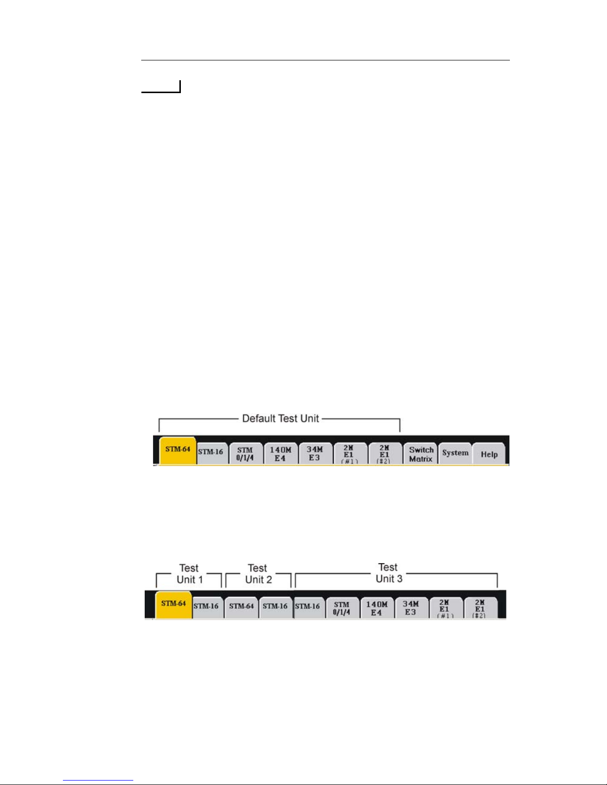
A Test Unit is a series of adjacent Circuit Packs and/or Protocol
Processors, installed in one NIC chassis, which can perform an Add/
Drop Mapping configuration. The Test Unit is based on a Circuit Pack's
internal addressing and provides Add/Drop Mapping functionality
between higher speed and lower speed Protocol Processors.
A NIC chassis may contain multiple tabs ranging from 40G down to
1.5M. When this type of configuration occurs, the Test Unit begins at
the left with higher speed processor, and each lower speed processor
drops down to the right.
When a second instance of a higher speed circuit pack is encountered, it
is considered the beginning of a second Test Unit. The image displayed
above shows a NIC that has 10 protocol tabs, representing 3 individual
Test Units.
Page 46
Document No. CO 004844K
38
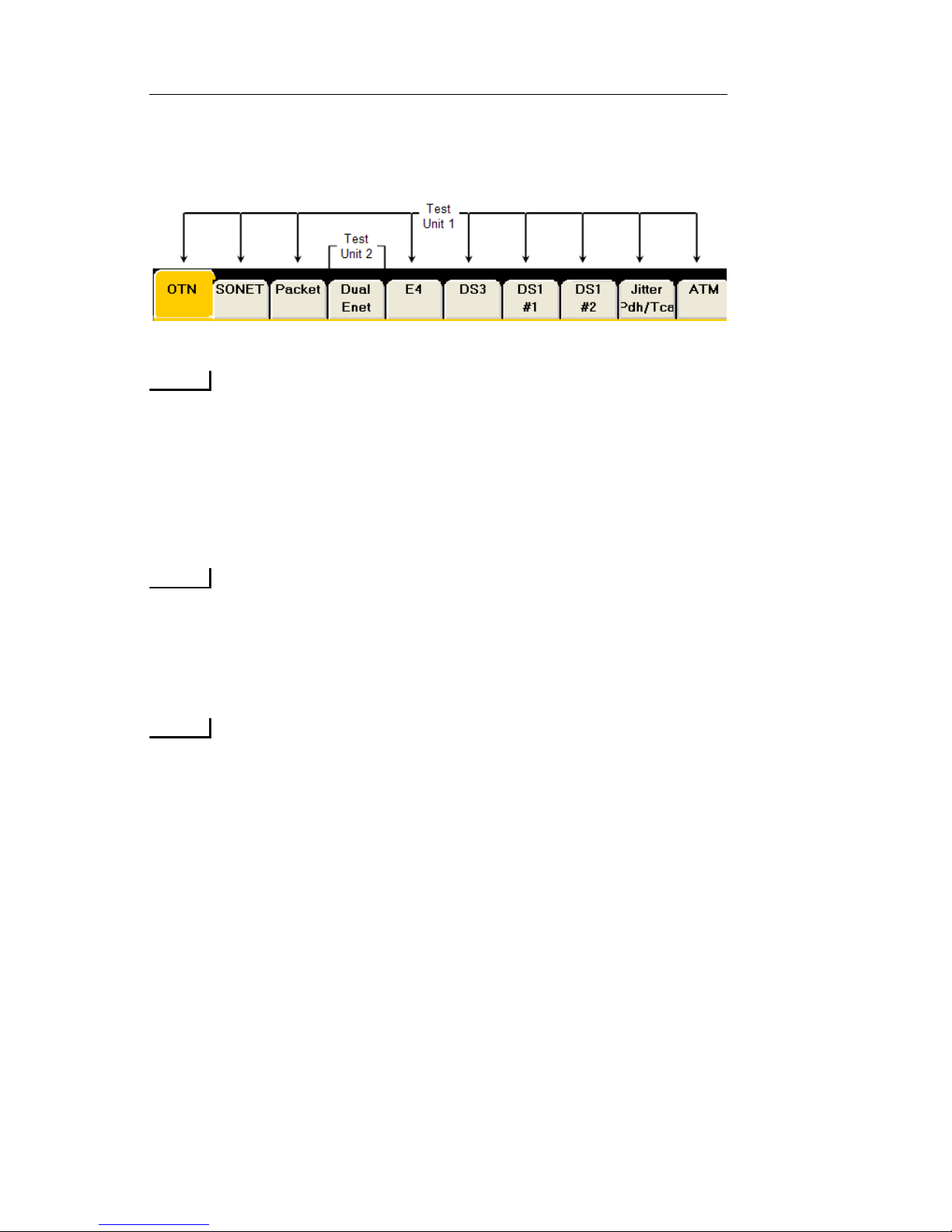
The image below shows a NIC unit with two Test Units. The
first Test Unit consists of the OTN, SONET, PACKET, E4,
DS3, DS1#1, DS1#2 and ATM tabs. the second Test Unit consists of both ports on the Dual Enet tab
.
NOTE
Some circuit packs however, such as High Density Ethernet,
may contain up to 13 individual Ports und er the one protocol
tab (HDEnet). In this case, each individual port is considered
its own Test Unit, since each port is operated independently
of each other and there are no Add/Drop opportunities with
any other circuit packs.
NOTE
The Add/Drop function from high Interface Rates to lower
Mapping configurations can then be setup between these processors using the Preset menu located in the common function buttons.
NOTE
When one protocol processor within a Test Unit is Locked or
Unlocked, then all of the protocol processors withi n that Test
Unit are automatically locked and unlocked as well.
Using the Lock Icon
The test set's multi-user functionality allows multiple simultan eo us
users to be connected to a portable test set. This includes a local user via
the test set's touch screen, as well as remote GUI users using the Remote
Control Application, and SCPI script command users.
To prevent users from interfering with each other, an individual user can
“Lock” and take control of a Test Unit. This is done using the Lock
icon that appears on the GUI. Security permission levels determine the
user's ability to lock and unlock a Test Unit. When you lock the Test
Unit, you can configure each of the protocol processors within the
Page 47
NIC Quick Reference Guide
39
selected Test Unit, start tests, and perform general product functions
without the worry of contending for resources with another user.
NOTE
Some NIC chassis’s may include more than one Test Unit, depending
on its configuration. See “Understanding Test Units” for more
information.
Lock Icon Guidelines
The following guidelines describe how to lock and unlock a Test Unit
using the Lock icon.
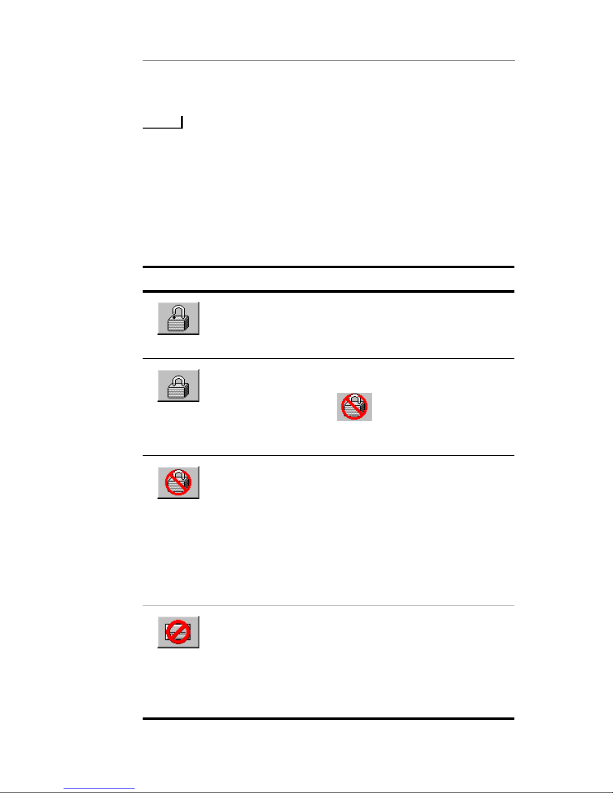
This icon Means
The Test Unit is unlocked and available. No
individual user has control of it. You can lock the
Test Unit by selecting this ico n. See “Locking a T e st
Unit” for instructions.
You have the Test Unit locked. You currently control
the Test Unit and can configure protocol pro cessors.
Other users will see on their GUI.
See “Unlocking a Test Unit That You Locked” for
instructions.
The test set is locked by another user. You can only
view protocol processor screens.
If you have Admin or Write privileges: You can
select this icon and force an unlock. See “Unlocking
a Test Unit Locked by Someone Else”for instructions.
If you do not have the proper user privilege: A
message appears stating that the protocol processor is
locked by the current owner. For example, “Protocol
Processor locked by User X.”
The circuit pack (and its associated protocol
processors) is out of service. A counter appears
indicating how long the circuit pack has been out of
service. A fault is also logged on the System > Fault
tab. The unit will need to be rebooted for the circuit
pack to become usable again. Contact Customer
Service if problem does not go away.
Page 48
Document No. CO 004844K
40
Unlocking a Test Unit Locked by Someone Else
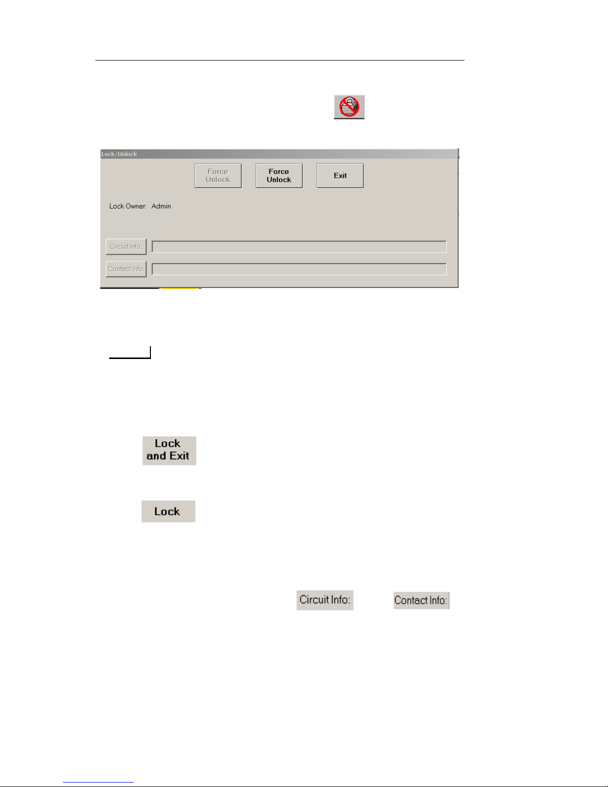
When a test set is locked by someone else the icon is displayed.
1. Select the Lock ico n. The Lock/Unlock dialog box appears.
2. Select Force Unlock. The command buttons change to “Lock and
Exit” and “Lock”.
NOTE
You must have Admin privileges to force the unlock.
3. Selecting one of the following causes the command buttons to
change to “Unlock and Exit” and “Unlock”, and the information
boxes become available.
– - Locks the unit and automatically closes the dialog
box. To enter notes after the dialog box closes, select the
locked icon to reopen the dialog box.
– - Allows you to enter note information in the Circuit
Info: and Contact Info: boxes before closing the dialog box.
The notes carry over to all protocol processors in the Test Unit.
When a different Test Unit is locked the user can enter notes
pertinent to it.
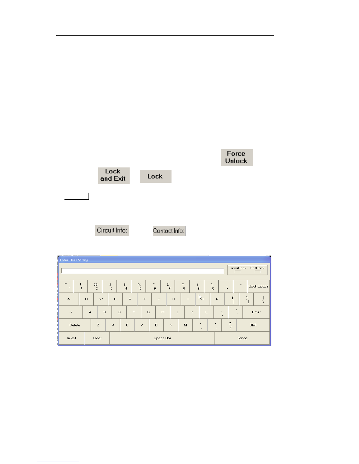
4. To enter note information, select and/or .
The Enter User String keyboard opens.
5. Type notes and select Enter. The notes appear in their associated
information box.
6. Select Exit to close the Lock/Unlock dialog box.
Page 49
NIC Quick Reference Guide
41
Unlocking a Test Unit That You Locked
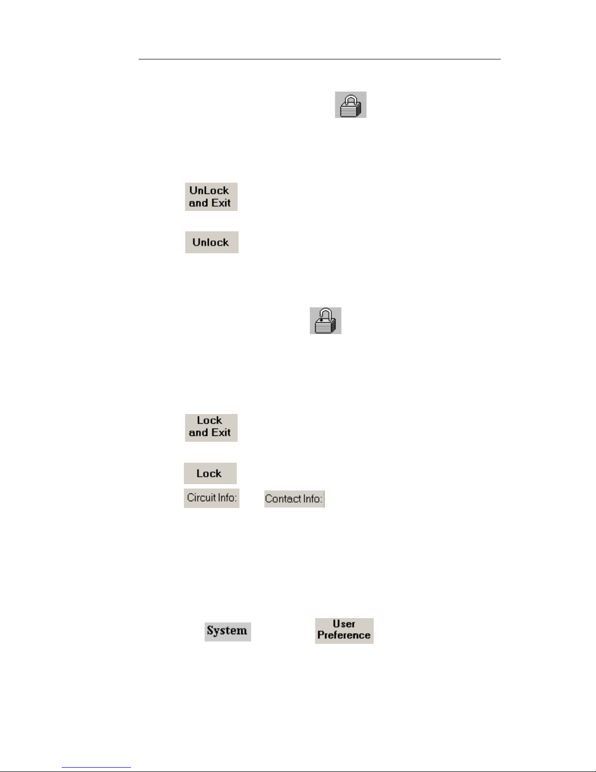
When a Test Unit is locked by you the icon is displayed.
1. Select the Lock ico n. The Lock/Unlock dialog box appears.
2. Selectin g one of the fol lowi ng causes the comm and buttons to
change to and “Lock”:
– - Unlocks the unit and automatically closes the dia-
log box.
– - Unlocks the unit without closing the dialog box.
Select Exit to close the Lock/Unlock dialog box.
Locking a Test Unit
When a Test Unit is unlocked the icon is displayed.
1. Select the Lock ico n. The Lock/Unlock dialog box appears.
2. Selectin g one of the fol lowi ng causes the comm and buttons to
change to “Unlock and Exit” and “Unlock”, and the information
boxes become available.
– - Locks the unit and automatically closes the dialog
box.
– - Allows you to enter note information in the
and boxes before closing the dialog
box. The notes carry over to all protocol processors in the Test
Unit. When a different Test Unit is locked the user can enter
notes pertinent to it. Select Exit to close the dialog box.
Configuring the Lock on Startup
To control the Lock's default state when the test set is started:
1. Select and choose . The User Preference
screen appears.
2. Select Startup Locking State.
Select Lock to automatically lock the test set when it is started.
Page 50
Document No. CO 004844K
42
Select Unlock to make the test set available to anyone wh en it
is started.
Adding Notes to a Test Unit
When you lock a Test Unit, you can add notes to the Add/Lock dialog
box that are pertinent to the Test Unit. Different Test Units can carry
their own specific notes.
To add notes to the Lock/Unlock dialog box for a test unit:
1. Choose the desired protocol processor and select the Lock icon.
The Lock/Unlock dialog box appears.
2. If the test uni t is locked by someone else, select and
choose or .
NOTE
Selecting Lock and Exit closes the dialog box. You can reopen the
dialog box by selecting the Lock icon again.
3. Select and/or . The Enter User String
keyboard opens.
4. Type notes and select Enter. The notes appear in their associated
information box.
5. Select Exit to close the Lock/Unlock dialog box.
Page 51
NIC Quick Reference Guide
43
To edit notes on the Lock/Unlock dialog box for a test unit:
NOTE
To edit the notes, the test unit must be placed in locked mode by the
immediate user.
1. Choose the desired protocol processor and select the Lock icon.
The Lock/Unlock dialog box appears.
2. Select and/or and make appropriate
changes using the Enter User String keyboard. Select Enter.
3. Select Exit.
Saving Customized Setting Configurations
This function allows you to save a customized configuration for all
protocol processor Transmit or Receive settings.
NOTE
The Save button saves settings for all protocol processors. For example,
when a customized settings configuration is saved while in a particular
protocol processor mode (for example, STM-4), the settings currently
configured for other protocol processors (for example, E1, E3, STM-16,
etc.) will also be saved with that setting configuration.
To save a configuration:
1. Create a test configuration using the Transmit and Receive
Settings screens.
2. Once you are done, select from the common function
buttons.
3. Select Save This Test Set, and the File Browser window appears.
4. Select File Name. A keypad appears.
5. Enter a name for the new configuration and select Enter when
done.
6. Select OK. The file is saved with an automatic file extension
of.set and appears in the File List.
Page 52
Document No. CO 004844K
44
Restoring a Settings Configuration
This function allows you to restore the unit’s factory default settings and
restores or recalls any saved configurations for all protocol processor
Receive or Transmit settings.
To restore a settings configuration:
1. Select from the common function bu ttons.
2. Select Restore This Test Set, and the Restore This Test Set
menu appears.
3. Select one of the fol low ing options:
– Protocol Mode <desired Protocol Mode> Changes the Test
Unit to the selected Protocol Mode, but does not modify any of
the Transmit or Recieve settings.
– Factory Defaults <desired Pr otocol Mode> Restores the Test
Unit to the default Transmit and Receive settings, and also
changes the Protocol Mode to the mode selected.
– User File: Recalls any saved configurations for a protocol pro-
cessor’s Receive or T ransmit settings. If this option is selected,
go to Step 4
4. From the File Browser window , select the name of the previously
saved settings configuration file to be restored.
5. Select OK. The settings configuration is restored.
Starting and Stopping a Test
Initiating and stopping a test is easily accomplished by using the Test
functionality for the selected protocol processor and common function
buttons.
Starting a Test
The Duration and Action After Duration function determine how long a
test runs and what activities occur at the end of the test.
To start a test:
1. Select the desired Proto col Processor tab.
Page 53
NIC Quick Reference Guide
45
2. Select Test and choose Set 1.
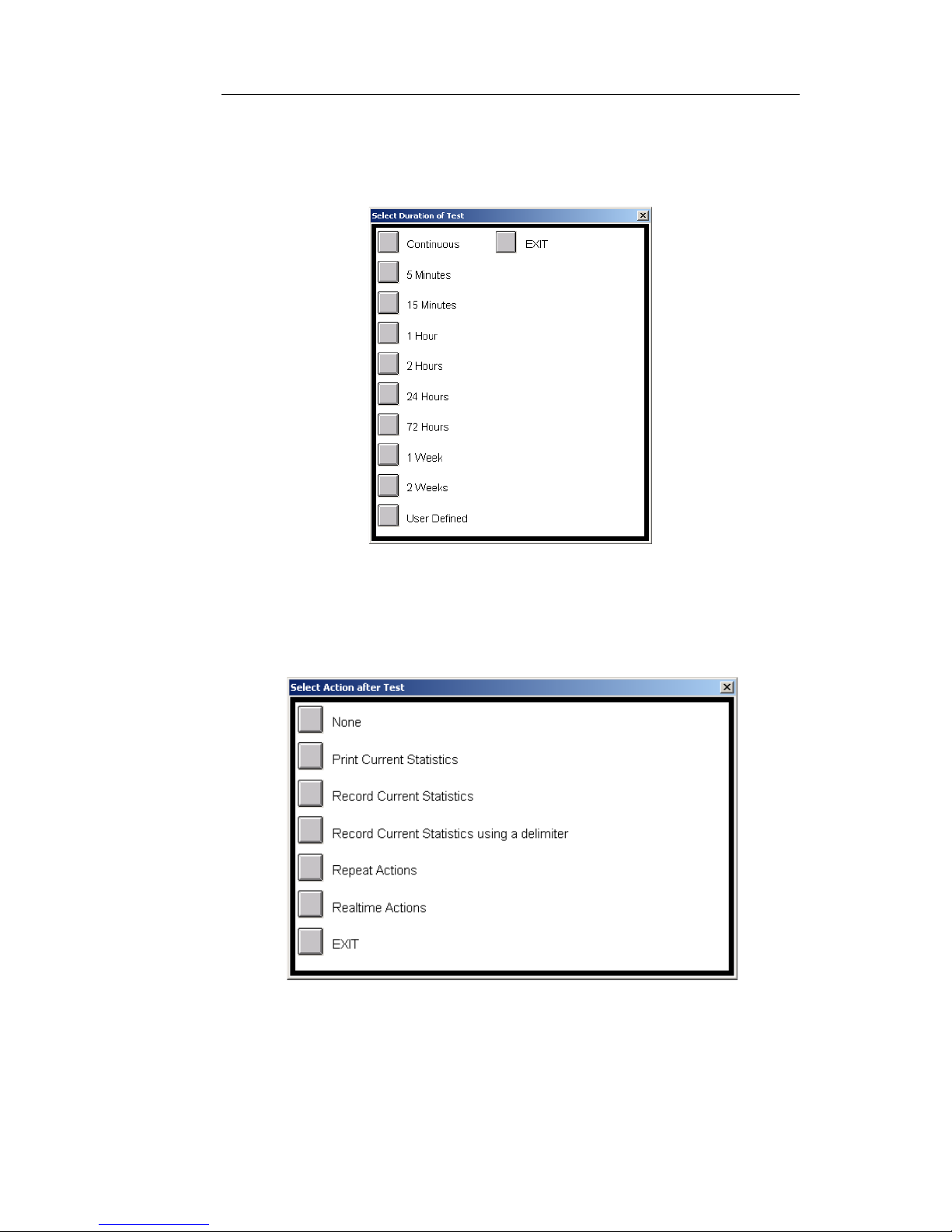
3. Select Duration. The Select Duration of a Test dialog box
appears.
4. Cho ose a duration time. The duration determines how long a test
runs.
5. Select Action After Duration. The Select Action after Test
dialog box appears.
6. Select an Acti on After Duration option. These options determine
what will happen at the end of the test duration.
Page 54

Document No. CO 004844K
46
NOTE
Real-time test reporting is only available locally (from the
touchscreen) on portable test sets.
When you select Repeat Actions, the Select Repeat Action after
Test dialog box appears. When you select Realtime Actions, the
Select Realtime Actions after Test dialog box appears. The table
below describes the options that appear on these additional
windows.
Repeat Test and
Realtime Test Options
Description
None No action occurs at the end of the test
duration.
Print Current Statistics Test results are printed to the attached
printer at the end of a timed test. The
timed test is not repeated.
Record Current Statistics Test statistics are printed to a file (.stat) at
the end of a timed test. The test does not
repeat.
Record Current Statistics
Using a Delimiter
T est statistics are printed to a file (.stat) at
the end of a timed test. The results appear
in a quote/comma-report format,
meaning that error and/or alarm values
are enclosed in quotes (“) and separated
by commas (,). The test does not repeat.
Print Statistics and
Repeat Tests
Note: This option
appears when Repeat
Actions is selected.
Test statistics are printed to a printer at
the end of the timed test and the test
restarts. This cycle continues until the
test is stopped by selecting Stop from the
common function button s , or by
changing the Action After Duration
value.
Page 55

NIC Quick Reference Guide
47
Record Statistics and
Repeat Test
Note: This option
appears when Repeat
Actions is selected.
T est statistics are printed to a file (.stat) at
the end of a timed test and the test
restarts. This cycle continues until the
test is stopped by selecting Stop from the
common function button s , or by
changing the Action After Duration
value.
Print Events and Repeat
Test
Note: This option
appears when Repeat
Actions is selected.
Test events are printed to a printer at the
end of the timed test and the test restarts.
This cycle continues until the test is
stopped by selecting Stop from the
common function button s , or by
changing the Action After Duration
value.
Record Events and
Repeat Test
Note: This option
appears when Repeat
Actions is selected.
Test events are printed to a file (.evt) at
the end of a timed test and the test
restarts. This cycle continues until the
test is stopped by selecting Stop from the
common function button s , or by
changing the Action After Duration
value.
Print Statistics/Events
and Repeat Test
Note: This option
appears when Repeat
Actions is selected.
Both test statistics and events are
automatically printed to a printer at the
end of the timed test and the test restarts.
This cycle continues until the test is
stopped by selecting Stop from the
common function button s , or by
changing the Action After Duration
value.
Record Statistics/Events
and Repeat Test
Note: This option
appears when Repeat
Actions is selected.
Both test statistics (.stat) and events
(.statE) are printed to a file at the end of a
timed test and the test repeats. This cycle
continues until the test is stopped by
selecting Stop from the common function
buttons, or by changing the Action After
Duration value.
Note: Both .stat and .stat files are
recorded.
Page 56

Document No. CO 004844K
48
Print Events and Repeat
Test
Note: This option only
appears when Realtime
Actions is selected.
Enables real-time reporting. Any event
that occurs during a real-time test is
automatically sent to the attached printer.
When the test duration expires, the test
restarts.
Record Events and
Repeat Test
Note: This option only
appears on the NIC test
set’s touch screen when
Realtime Actions is
selected.
Enables real-time reporting. Any event
that occurs during a real-time test
automatically prints to a file (.evt). When
the test duration expires, the test restarts.
Print and Record Events
and Repeat Test
Note: This option only
appears on the NIC test
set’s touch screen when
Realtime Actions is
selected.
Enables real-time reporting. Any event
that occurs during a real-time test
automatically prints to a printer that is
attached to the NIC unit and prints to a
file (.evt). When the test duration expires,
the test restarts.
Print Events
Note: This option only
appears on the NIC test
set’s touch screen when
Realtime Actions is
selected.
Enables real-time reporting. Any event
that occurs during a real-time test
automatically prints to a printer that is
attached to the NIC unit. The test does
not repeat.
Record Events
Note: This option only
appears on the NIC test
set’s touch screen when
Realtime Actions is
selected.
Enables real-time reporting. Any event
that occurs during a real-time test
automatically prints to a file (.evt). The
test does not repeat.
Page 57
NIC Quick Reference Guide
49
7. Select . The test starts and the Elapsed Time counter
resets to 0.
Stopping a Test
The Stop common function button stops the reporting of received data
and takes a snapshot of error, alarm, and event activity. When the Stop
button is selected, the following occurs:
All statistics logged and reported by the Performance Monitor-
ing function stop.
All alarm, error, and event statistics logged and reported by the
Results function stop.
All elapsed time and duration counters stop.
To stop a test before the test duration expires:
Select the common function button.
Restarting a Test
Select the common function button. The test and statistics clear
and the Elapsed Time counter restarts at zero.
Pausing and Resuming a Test
1. Select the desired Proto col Processor tab.
2. Select Test and choose Set 1. The Duration and Action After
Duration functions appear.
Print and Record Events
Note: This option only
appears on the NIC test
set’s touch screen when
Realtime Actions is
selected.
Enables real-time reporting. Any event
that occurs during a real-time test
automatically prints to a printer that is
attached to the NIC unit and prints to a
file (.evt). The test does not repeat.
Page 58

Document No. CO 004844K
50
• To pause a test, select Pause Test. When Pause is selected, the
system will stop collecting data, but the elapsed time counter
will continue. Additionally, when Pause is selected, a red Test
Paused LED will appear in the LEDs/Quick Status area.
• To resume the test, select Resume Test. The Test Paused LED
turns white with red text, indicating that a pause has previously
occurred. A restart or new test will clear the LED’s history.
NOTE
The events occurring while in pause mode will be recorded in the
Event Log.
Printing a Real-Time Test
A real-time test records and generates a report of any events (alarms,
errors, or power interruptions) that occur while the test set is monitoring
a customer's circuit. The reports, generated in real time, can be sent to
an attached printer, a file, or both.
NOTE
Real-time test reporting is only available locally (from the touchscreen)
on portable test sets.
The report contains the following information:
• A user-defined header
• A brief list of product settings
• Test start time and date
• Event activity as it occurs during the test
• A "print alive" message, which can be configured at a specified
time to ensure the user that the real-time test is still active
• A statistical report, produced at the conclusion of the test, pro-
viding a summary of reported events. If no events occur during
Page 59

NIC Quick Reference Guide
51
the test duration, a completion message, indicating that no
problems were found, is printed.
Real-time test settings and accumulated results are not discarded if a
power interruption occurs. The results are saved in 15-minute
increments. When power is restored to the test set, the real-time test will
continue from where it was prior to the power interruption. The power
interruption event will appear in the real-time report.
IMPORTANT
Before starting a real-time test, set the Security System Lock. This will prevent
remote users from accessing the test set while a test is in progress.
To set up and start a real-time test:
1. Select the desired Proto col Processor tab.
2. Select Test and choose Set 1. The Duration and Action After
Duration functions appear.
3. Select Action After Duration. The Select Action after Test
window appears.
4. Select Realtime Actions. The Select Realtime Actions after Test
dialog box appears.
NOTE
The Select Realtime Actions after Test dialog box only contains
realtime actions to choose from when you are working from the
NIC test unit.
5. Select a real-time test option:
• Print Events and Repeat Test
• Record Events and Repeat Test
• Print and Record Events and Repeat Test
• Print Events
• Record Events
• Print and Record Events
The Realtime Setup Parameters window appears.
Page 60
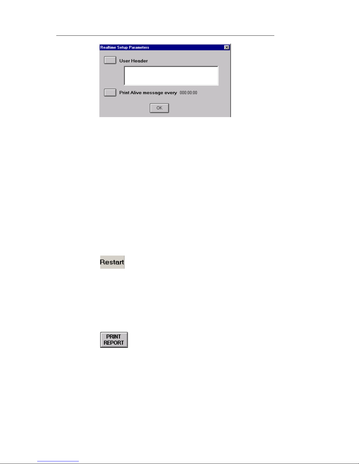
Document No. CO 004844K
52
6. Select User Header to enter a user-defined header. The header,
which can be up to 64-bytes in length, serves as a brief description
of the test. After entering a header using the keypad, select Enter.
7. Select Print Alive message. The Enter Duration window appears.
8. Set the tim e parameter, which determines if and when a Print
Alive message is generated. A value of 0 disables the messaging
function.
9. Select OK. The header name and duration setting appear on the
Realtime Setup Parameters window.
10. Select OK to clos e the Realtime Setup Parameters window.
11. Select Duration. The Select Duration of Test window appears.
12. Enter how long the test will run.
13. Select to start the real-time test. The Elapsed Time
counter, located in the top right corner, resets to 0.
Printing and Saving Reports
The Print Report button allows you to Print and Save test reports.
1. Select from the Common Function Buttons row at the
bottom of the screen. The Report Setup dialog box appears.
Page 61
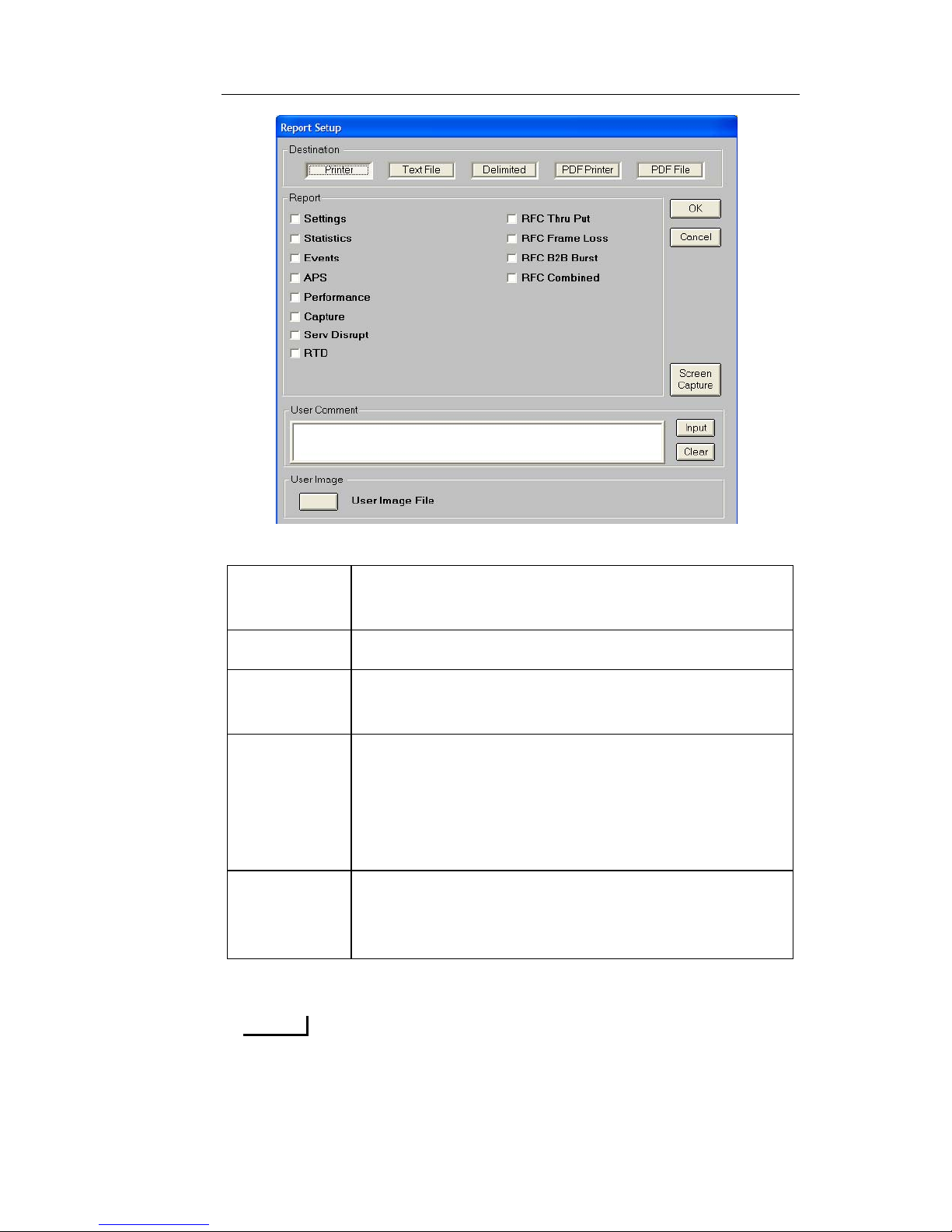
NIC Quick Reference Guide
53
2. Select the Desti nation Printer or File type.
3. Choose the Report type to be printed or saved.
NOTE
The most common report is the Statistics report, which contains a
complete list of error and alarm statistic information as well as
other counts that pertain to the test performed.
Printer The selected report is sent to either the Parallel
printer port or the USB printer port.
Text File The selected report is saved as an ASCII text file.
Delimited The selected report is save as a text file, using
Comma Delimited (CSV) file format.
PDF
Printer
The selected report is sent to either the Parallel
printer port or the USB printer port. The format of
the report is similar to the PDF file which allows a
User Image file (such as your company’s logo) to be
printed at the top of the report.
PDF File The selected report is saved as a PDF file, and this
format allows a User Image file (such as your company’s logo) to be saved at the top of the report file.
Page 62
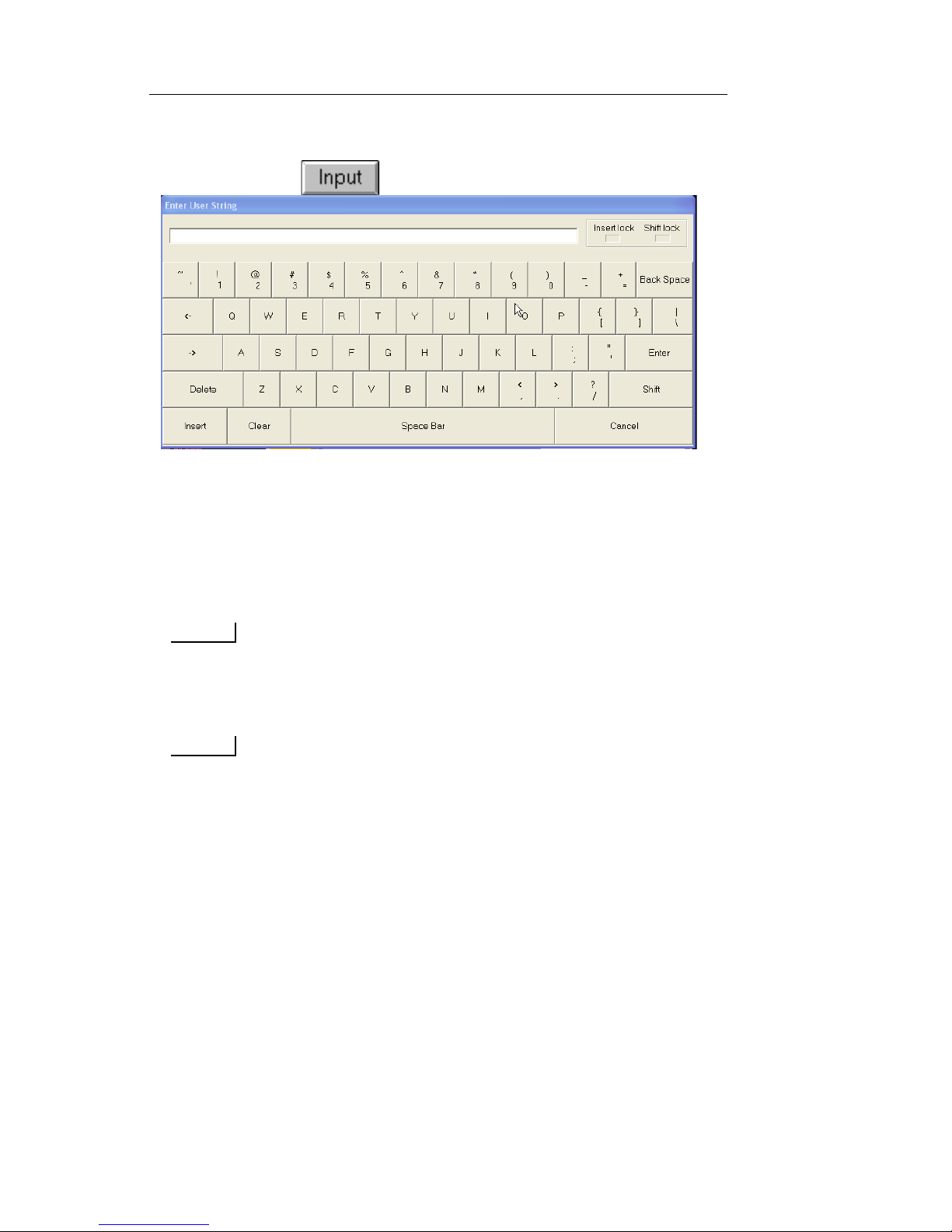
Document No. CO 004844K
54
4. If you want to include some additional text information in the
Header of the generated report, you can enter it by selecting the
Input button to open the keyboard screen.
5. Using the touch screen, enter in your comments and press the
Enter button.
6. If printing a PDF report to PDF Printer or PDF File, then you can
select a User Image File (such as your company’s logo image) to
be printed/saved to the top of the report file.
NOTE
Image files can be .JPG, .PNG, .GIF or .BMP, and images appear
their best when their dimensions are near 748 x 154 pixels.
Smaller images will be stretched, and may look distorted.
NOTE
If printing the report using the NIC’s local GUI, then the image
file must be copied to the NIC’s FTP\APPL folder before
selecting Print Report.
If printing the report using the NIC’s Remote GUI, then the image
file must be copied to the
C:\ProgramFiles\GalaxyNIC\Compat<feature set> folder before
selecting Print Report.
7. Press OK to begi n printing or saving the report.
8. If pri nting to a Text File, Delimit ed, or PDF File, then the File
Browser dialog box opens, allowing you enter a report file name.
Page 63
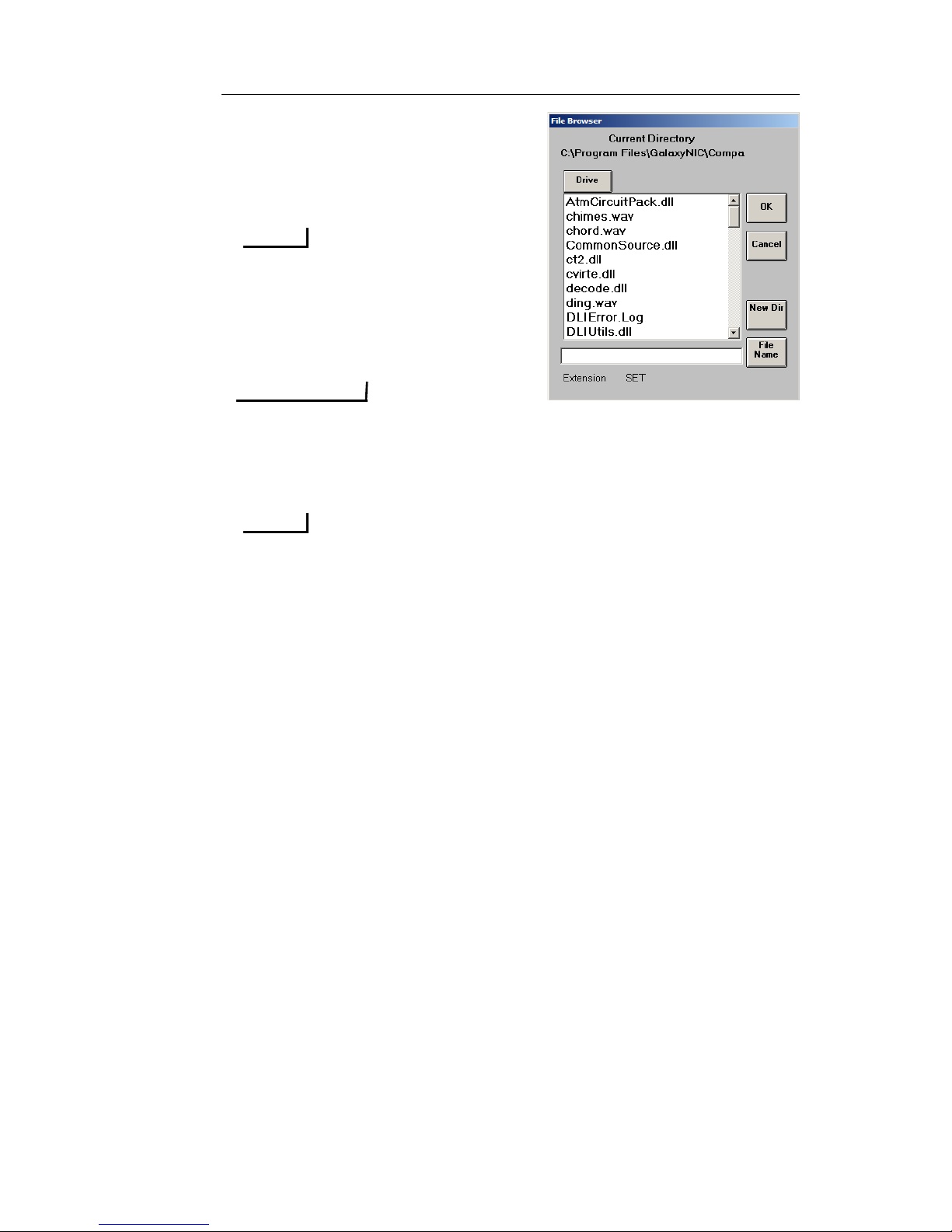
NIC Quick Reference Guide
55
9. Select Fi le Name, and using the
Key board screen that appears,
enter the File Name of your
choosing.
NOTE
File names should be limited to 8
characters, without any spaces.
The File Extension will
automatically be entered, based
on the report type selected.
IMPORTANT
If you click OK in the File
Browser dialog box WITHOUT ENTERING A FILE NAME,
the File Browser dialog box will go away and your REPORT
WILL NOT BE SAVED.
NOTE
It is important to note that, in addition to naming a report file that
is being printed and saved, the File Browser dialog box also
provides capabilities for you to do the following: (a.) you can
select existing files to be overwritten (use caution when
overwriting existing files); (b.) you can navigate upward or
downward (the highest level is FTP\APPL\) to a different
directory on the NIC for saving your report print file; (c.) you can
create a new directory (in FTP\APPL\ or lower) for saving your
report print file; or (d.) you can use the Drive button to navigate to
a USB card for saving your report print file.
Printing a Displayed NIC Screen Capture
The Screen Capture function allows you to print a screen that is
currently displayed on a NIC unit using the test set’s touch screen. This
function captures the screen image and converts it into a bitmap (.bmp)
file that can be printed to a printer that is locally-attached to the NIC
unit or transferred later to a PC for printing.
To print a displayed NIC screen at the NIC unit, perform the following
steps:
Page 64
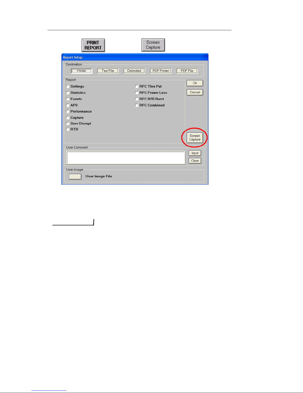
Document No. CO 004844K
56
1. Select and choose
2. The im age is saved to the defau lt file name, “Screen1.bmp,” in
the NIC unit’s default location:
D:\DLI\FTP\APPL\APPL\
IMPORTANT
The same file name (Screen#.bmp) is automatically used every
time when initiating a screen capture. The # will automatically
increment to the next number when multiple screen captures are
saved.
3. To print any screen image file (<filename>.bmp) that has been
saved on the NIC unit, you must first transfer the file from the
NIC unit to a PC. This can be done by either (a) copying the file to
a locally-attached USB flash storage device that is locally
attached to the NIC unit, and then plugging that storage device
into a PC, or (b) by using the NIC unit’s built-in FTP Server
functionality for a PC-initiated FTP file transfer from the NIC unit
to the PC via a remote FTP connection.
Page 65
NIC Quick Reference Guide
57
File Services
Viewing a File
1. Select and choose . The File Services screen
appears.
2. Select a file from the File List.
3. Select View. The contents of the file appear in the View window.
4. Use or (a toggle button) to display the file in
Hex or ASCII format.
IMPORTANT
Screen capture files with .BMP file extensions cannot be
viewed. Attempting to view these file types might cause the
GUI to stop responding for several seconds.
Transferring Files to USB or Compact Flash Drive
A file can be transferred from the test set to a remote device (PC running
Remote GUI or using FTP) or to a local device (USB or Compact Flash
drive).
NOTE
If using the FTP function, see the NIC Users Manual for detailed
instructions on transferring files to PC.
NIC units manufactured after 2006 with either System Controller II or
System Controller III modules support USB flash drive technology.
• Units with System Controller II will have a row of small
LEDS on the left edge of the PCMCIA slots.
• Units with System Controller III will have a row of small
LEDS on the left edge of the System Drive slot, as well as
three USB 2.0 connector ports.
• Units manufactured prior to 2006 support Compact Flash technology, using PCMCIA to CF adaptor.
IMPORTANT
Make sure that a USB flash drive or CF/PCMCIA card is
connected to the NIC before selecting the File Services button.
Page 66
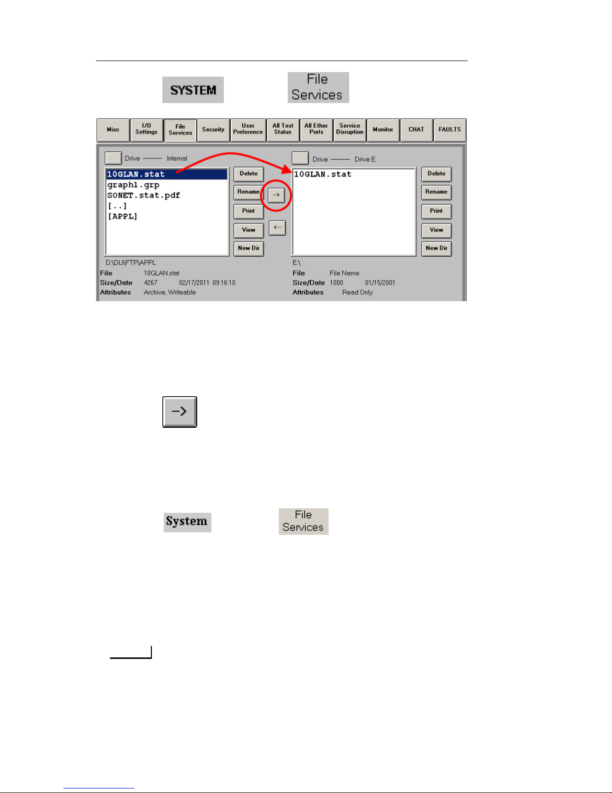
Document No. CO 004844K
58
1. Select and choose . The File Services
screen appears.
2. From the Right file list box, set Drive to Drive E.
3. From the Left file list box, set Drive to Internal.
4. Select one or more files (click once to highl ight filename) from
the Left file list box.
5. Select . The copied file(s) will appear in the Right file list
box.
6. Rem ove Flash drive, and transfer files to PC/Laptop.
Renaming a File
1. Select and choose . The File Services screen
appears.
2. Select a file from the Left file list box (click once to highlight the
filename).
3. Select Rename. A keyb oard appears.
4. Use the keyb oard to enter the new file name.
NOTE
File names should be limited to 8 characters to left of the File
Extension, without any spaces.
Page 67
NIC Quick Reference Guide
59
NOTE
The original File Extension should be maintained, however you
are able change Text files to a .txt file extension.
5. Select Enter from the keyboard. The file is renamed.
Deleting a File
1. Select and choose .
2. Select a file from the Left file list box (click once to highlight the
filename).
3. Select Delete. A confirmat ion message appears.
4. Select Yes. The file is deleted.
NOTE
If you do not have authorization to delete files, an “Access
Denied” message appears.
Displaying Serial Numbers and Software Revision
The “About” function displays the following information:
NIC’s Product Name and Prod uct Serial Number
NIC’s software Feature Set version
NIC’s hardware Serial Numbers and ECN revision levels
NIC’s hardware Software Versions and FPGA versions
NIC’ s hardware License Key
NIC’s Usage Time, which is a run-time odometer listing the
accumulated number of hours of operation
Save button used to save the About window information to file
To view this information:
1. Select .
2. Select . The Miscellaneous functions appear.
3. Select About this product. The About dialog box appears.
Page 68
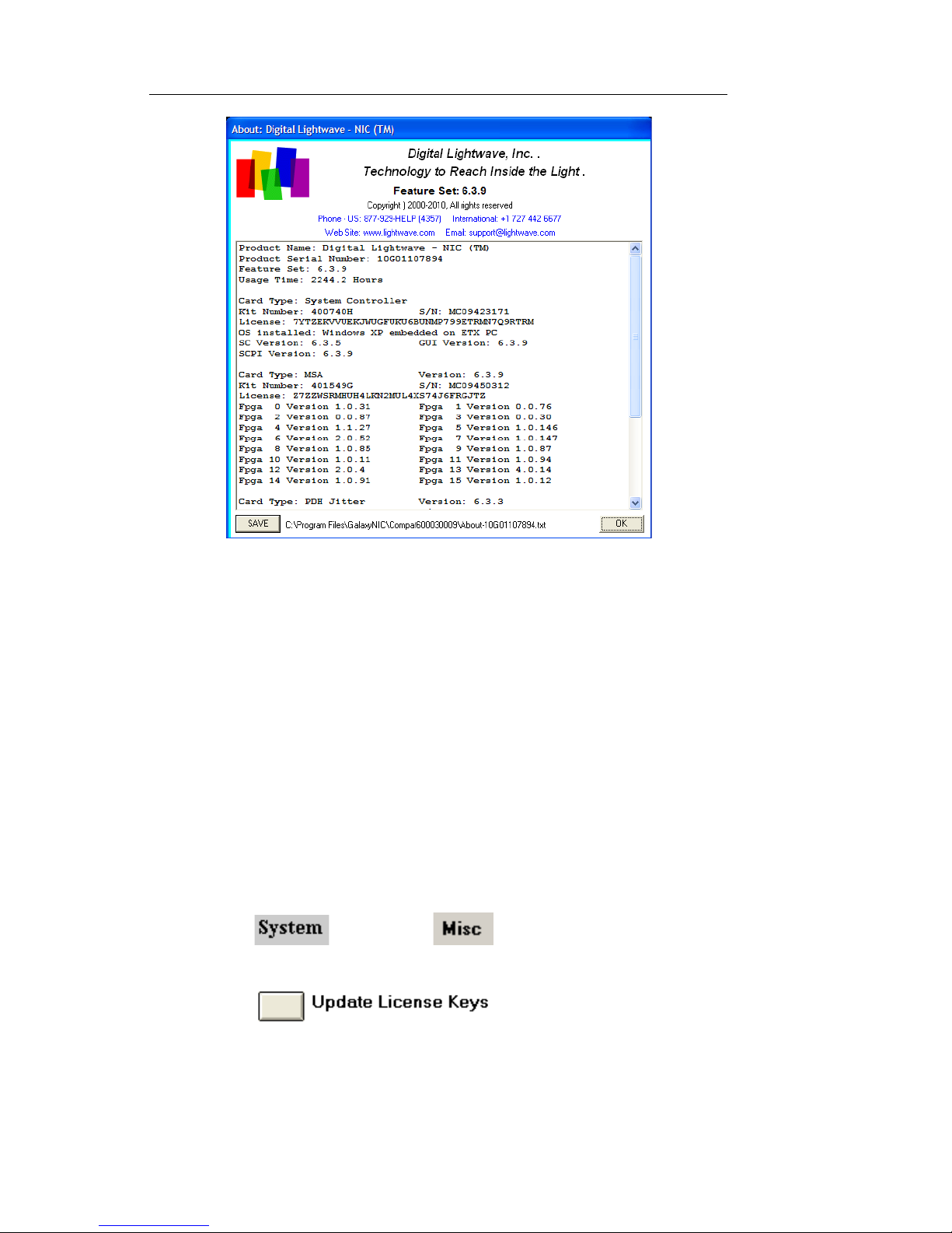
Document No. CO 004844K
60
4. Select SAVE to save the About window information to a file.
5. Select OK to close.
Entering a new License Key
The License Key function allows you to enable functionality that you
may not have initially purchased. If you wish to obtain more functionality for your test set, contact your Digital Lightwave sales representative
for available options and a price quotation. After receiving your payment, a Digital Lightwave Customer Service representative will provide
you with an updated License Key to activate the requested feature(s).
To enter a new license key:
1. Select and choose . The Miscellaneous
functions appear.
2. Select . The Update License Key
menu appears listing each of the circuit packs in the NIC unit that
can be licensed.
Page 69

NIC Quick Reference Guide
61
3. Select the circuit pack that the license key was modified for. A onscreen keyboard appears.
4. Enter the new licen se key into the text box, making sure to enter
capitalized letters.
• If using the on-screen keyboar d, you will need to pr ess the Shift
key to enter capital letters, then press the Shift key again to
enter numbers, and so on.
• However if you have an external USB keyboard available, the
License Key entry process is much easier by using the Caps
Lock feature when typing the key.
5. Select Enter when done.
6. Repeat steps 2 through 5 if updating the license key for more than
one circuit pack.
7. For the changes in the licensed options to take effect, reboot the
test set by using the Reboot button in the I/O settings.
Setting Time and Date and Time Zone
To Manually set the time:
1. Select and choose . The Miscellaneous
functions appear.
2. Select Unit Time, Date, Zone. The Date/Time an d Time
Zone menu appears.
3. Select Manually Adjust Date/Time.
4. Select Time.
Page 70
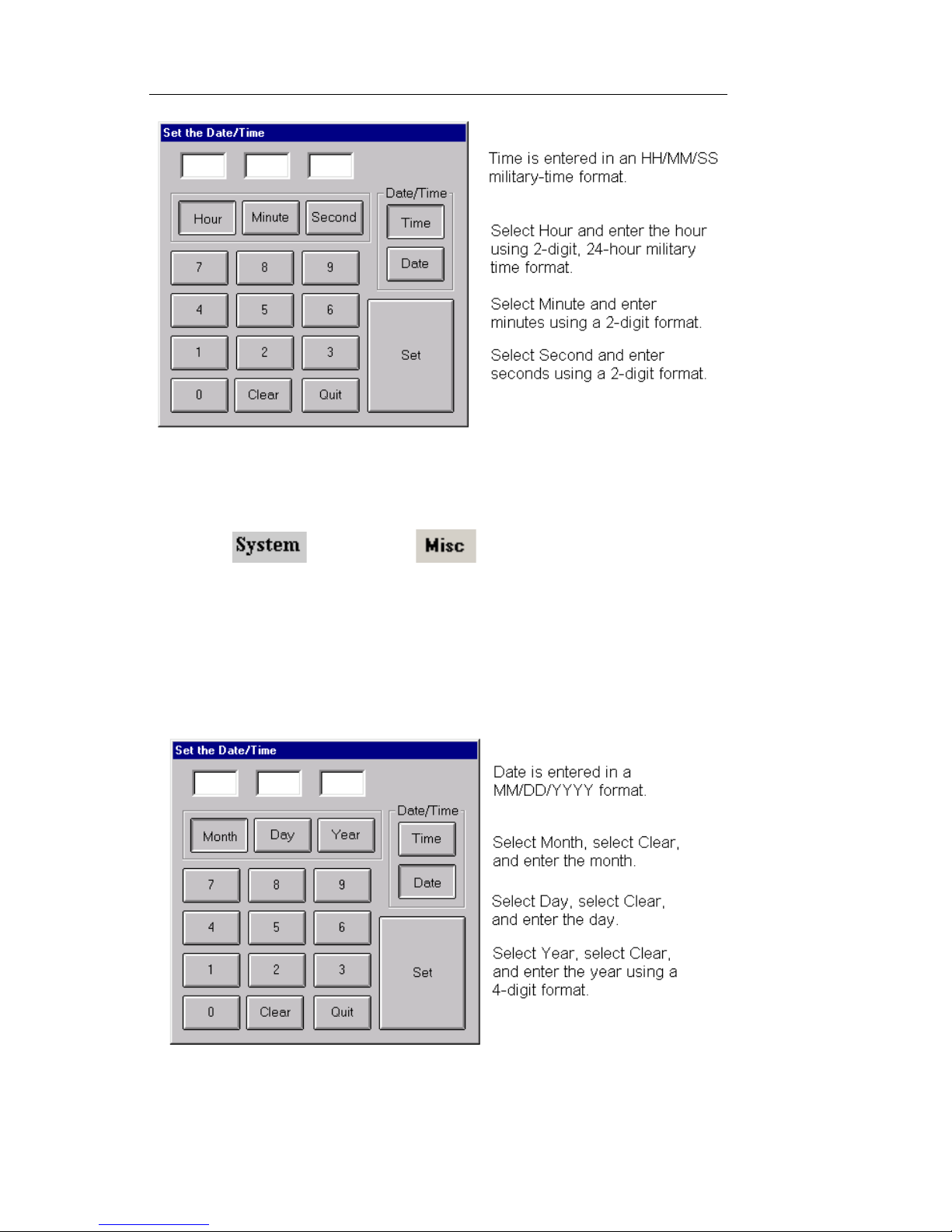
Document No. CO 004844K
62
5. Enter the time, and select SET.
To set the date:
1. Select and choose . The Miscellaneous
functions appear.
2. Select Unit Time, Date, Zone. The Date/Time and Time
Zone menu appears.
3. Select Manually Adjust Date/Time.
4. Select Date.
5. Enter the date, and select SET.
To close the window without making changes, select Quit
Page 71

NIC Quick Reference Guide
63
To Automatically set the time and date:
1. Select and choose . The Miscellaneous
functions appear.
2. Select Unit Time, Date, Zone. The Date/Time an d Time
Zone menu appears.
3. Select Automatically Adjust Date/Time.
4. The Enter User String keyboard appears.
5. By default the Networ k Time Server is programmed as
time.nist.gov.
6. Enter the Na me or IP Address of the a different Network/
Internet Time Server if desired, and select Enter when
done.
7. Some companies internal network servers require you to
specify your network’s Domain Name Server (DNS), in
order for this feature to access an external Time Server.
a. Click on I/O Settings, and enter your net work’s DNS in the
Domain Name field (if it is currently not entered).
8. Reboot the unit for the network settings change to take
effect.
To Adjust the Time Zone and Daylight Saving Time:
1. Select and choose . The Miscellaneous
functions appear.
2. Select Unit Time, Date, Zone. The Date/Time an d Time
Zone menu appears.
3. Select Adjust Time Zone. The Time Zone Properties window appears.
4. From the drop-down menu, select the Tim e Zone for the
location you are in.
5. If your time zone semi-annually adjusts its clocks for Day-
light Savings Time then check the “Automatically
adjust clock...” setting, otherwise uncheck this setting.
Page 72

Document No. CO 004844K
64
External Clock In St atus
NIC units manufactured with System Controller III (3 USB ports) have
two External Clock In and Clock Out ports; one port for Bantam cables
and one port for BNC cables.
The System Controller auto-detects the status of which Clo ck In
port is actively being used.
At the bottom of the System tab > Misc screen, there is an
External Clock In Status window which displays the following
information.
External Clock In
Status
Description
Internal Reference Neither Clock In port has active External
Clock In connection
Pre-Locked (BNC) Briefly displays as the System Controller
detects that an External Clock was connected
to the BNC Clock In port.
Pre-Locked (Bantam) Same as above, but for the Bantam Clock In
port.
Locked (BNC) The System Controller was successfully able
to synchronize to the External reference Clock
connected to the BNC Clock In port, and verified that it matched the External Clock setting.
Locked (Bantam) Same as above, but fo r the Bantam Clock In
port.
Loss of Lock (BNC) Briefly displays when the System Controller
detects that the External Clock was disconnected from the BNC Clock In port. The System Controller will first verify if a valid
reference clock is connected to the other
Clock In port. If another Clock is not found, it
will revert back to Internal Reference.
Loss of Lock (Bantam) Same as above, but for the Bantam Clock In
port.
Page 73
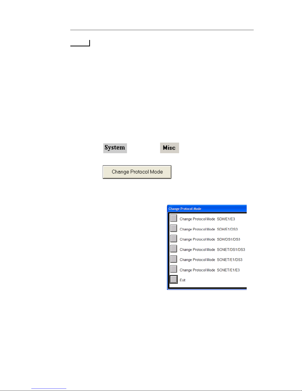
NIC Quick Reference Guide
65
NOTE
Both Clock Out ports are always active, regardless of the
Clock In status. The External Clock setting configures the
Clock Out frequency.
Configuring a Protocol Mode
NIC units can be configured to operate in SONET or SDH mode and
E1/E3, DS1/DS3 and E1/DS3 modes, depending on the configuration of
the NIC.
To change protocol processor modes:
1. Select and choose . The System functions
appear.
2. Select . The protocol options appear.
3. Select a protocol processor mode. The touch screen will update to
the protocol processor mode specified.
• Units with SONET/SDH
hardware will have options for
SONET and SDH modes.
• Units with PDH hardware will
have options for E1/E3, DS1/
DS3, and E1/DS3 modes.
• Units with both SONET/ SDH
and PDH hardware will have
combined options for all
modes.
Page 74

Document No. CO 004844K
66
Restoring Factory Defaults
To restore the unit’s factory transmit and receive settings:
1. Select and choose . The System functi ons
appear.
2. Select . The default options appear.
3. Select the Restore to Factory Default option for the desired protocol processor mode that you want the unit to be configure for
when after the defaults have been loaded.
• Units with SONET/SDH
hardware will have options
for SONET and SDH modes.
• Units with PDH hardware
will have options for E1/E3,
DS1/DS3, and E1/DS3
modes.
• Units with both SONET/
SDH and PDH hardware will
have combined options for all
modes.
Configuring the Ethernet Port
The test set can be remotely controlled using the Remote GUI application or SCPI script commands through the System Controller’s Ethernet
port. The test set supports dynamic IP addressing, using Dynamic Host
Connection Protocol (DHCP) and static IP addressing.
Configuring Ethernet Parameters
IMPORTANT
When Ethernet port parameters are changed, the test set must be restarted for
the changes to take affect.
1. Select an d choose .
Page 75
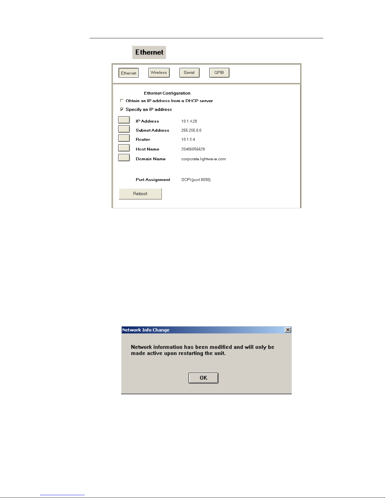
NIC Quick Reference Guide
67
2. Select . The Ethernet Configuration functions appear.
3. Select one of the fol low ing:
• Obtain an IP address from a DHCP server
• Specify an IP address
Obtain an IP address from a DHCP server
The test set uses the network’s DHCP server to dynamically assign it an
IP address.
a. Select the O b tain an IP address from a DHCP Server check
box. The Network Info Change dialog box appears.
b. Select OK.
If you decide that you do not want this selection, choose the
Specify an IP address check box and follow the steps for
that option.
Page 76

Document No. CO 004844K
68
Specify an IP address
a. Select the Specify an IP address check box.
b. Select IP Address. The Enter IP Address keypad appears.
c. Enter the new IP address for the test set and select OK.
WARNING
IP addresses 192.168.138.000 through
192.168.138.255 are reserved and must not be used. A
system conflict can occur if these IP addresses are
entered.
If you must use an IP address in the range of
192.168.x.x, then you must set the Subnet Address to
255.255.255.0.
d. Select Subnet Address. A keypad appears.
e. Enter the Subnet address and select OK.
f. Select Router. A keypad appears.
g. Enter the Router address and select OK.
h. Host Name and Domain Name settings only need to be entered
under special conditions.
i. Port Assignment. The Ethernet port assignment is automatically
enabled for SCPI (port 8090).
j. Select . The Reboot the Unit dialog box appears.
k. Select OK.
l. Afte r all unsaved data is written to the disk, the test set restarts.
If the test set does not successfully reboot turn it off
manually by toggling the On/Off switch to Off and restarting
it.
Sending Email Alerts
Before using the email alert feature, check with your Network
Administrator to verify that your email account is set up to accept and
forward SMTP mail.
IMPORTANT
After setting the email alert options, the protocol tab for which the error/alarms
have been configured, must be selected, or you must be in All Tests mode.
Email alert messages will not be generated if these conditions are not met.
Page 77
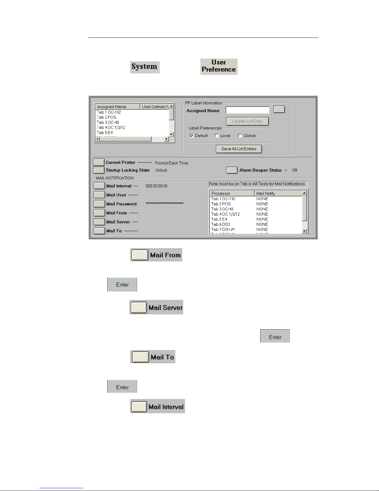
NIC Quick Reference Guide
69
To set up email alerts:
1. Select and choose . The User Preference
screen appears.
2. Select . A keypad appears.
3. Usin g the keypad, enter the sender’s email address and press
.
4. Select . A keypad appears.
5. Using the keypad, enter the email server address (for example,
ms1 or mail.yourcompanyname.com) and press .
6. Select . A keypad appears.
7. Using the keypad, enter the recipient’s email address and press
.
8. Select . The Select Duration of Test window
appears.
9. Select the desired test duratio n period. The test duration
determines when the system checks for an error or alarm.
Page 78

Document No. CO 004844K
70
For example, when you set up a mail interval of 15 minutes on
OC-1/3/12 for all errors/alarms and then select the OC-1/3/12 tab,
the result is that at the first live error/alarm incident an email
message is sent to the recipient. After 15 minutes has elapsed the
system looks for the next live error/alarm incident and sends
another email message. This 15-minute loop continues until you
reset the email notification configuration.
IMPORTANT
This process is not active unless the configured protocol tab or
All Tests is selected.
10. In the Processor/Mail Notify section , select th e protocol
processor that you want monitored. The Select Error/Alarm Mail
Notification window appears.
.
11. Select the desired error/alarm type. You can select a specific
type or all errors and alarms. When monitoring multiple protocols,
each protocol can be configured for its own error/alarm type.
To configure multiple protocols for email notification, select
another protocol processor after choosing the error/alarm type for
the previous one.
IMPORTANT
To activate the email notification function for multiple protocols
Page 79
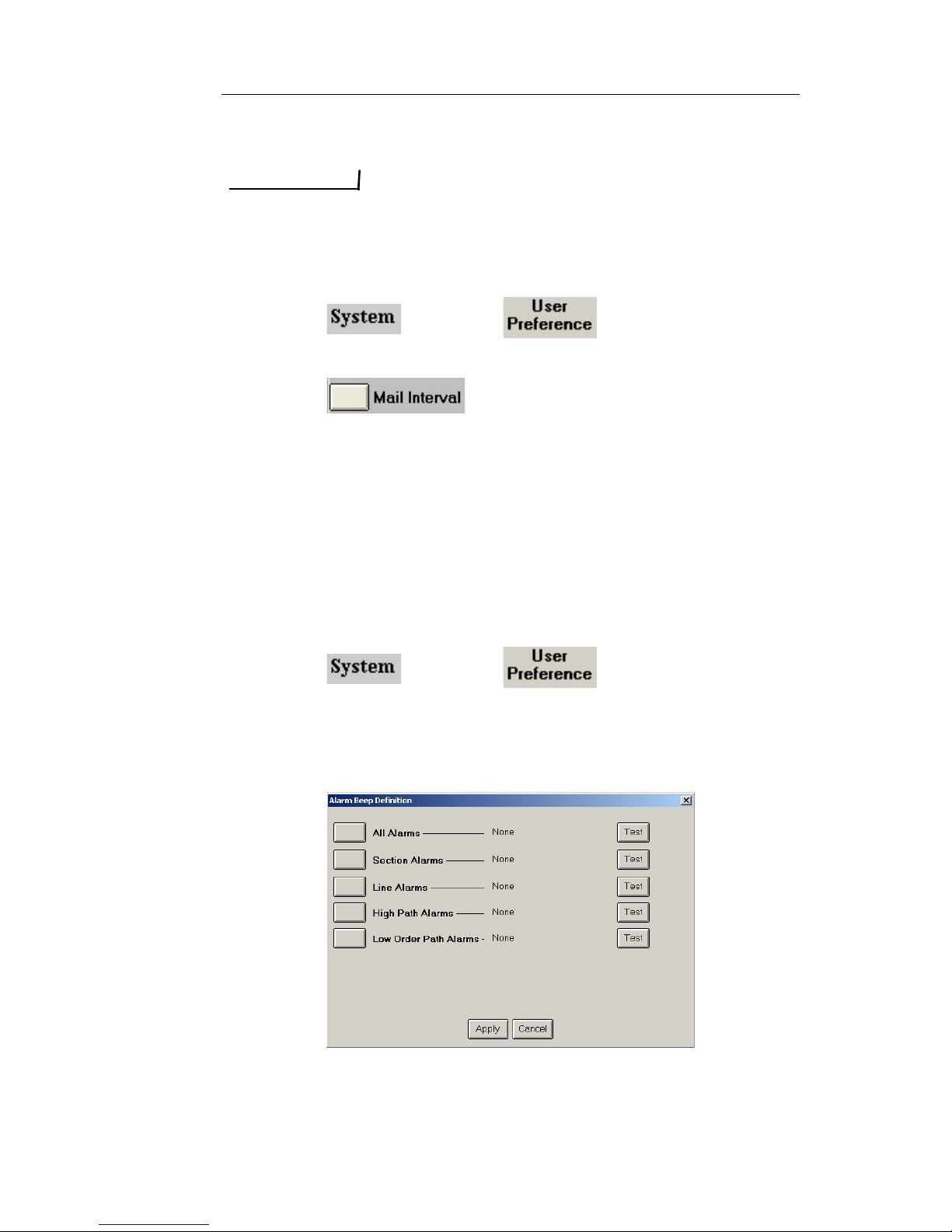
NIC Quick Reference Guide
71
you must select All Tests after the configurations are
completed.
IMPORTANT
These configuration settings DO NOT persist after the test set has been
rebooted.
To terminate email alerts:
1. Select and choose . The User Preference
screen appears.
2. Select and choose OFF.
Using Alarm Beeper Status
WAV file sounds can be associated with an alarm event. When using
the test set’s touch screen, a total of 10 sounds are available. When
using the Remote Control Application, up to a total of 16 sounds can be
used. This includes customized WAV files that can be copied to your
Remote Control’s installation directory on your PC.
Assigning WAV Files to an Alarm
1. Select and choose . The User Preference
screen appears.
2. Select Alarm Beeper Status.
3. Select On or Maintenance. The Alarm Beep Definitions appear.
4. Select an alarm type. The Select Alarms Sound dialog box
appears
Page 80

Document No. CO 004844K
72
5. Select a sound. Th e sound selection uses the WAV file’s name.
For example, chord.wav appears as Chord.
6. Select Test to hear the WAV file and determine if this is the sound
you want to associate with the alarm.
7. Select Apply. The Alarm Beep Definition window closes.
Turning Off All Alarm Sounds
1. Select Alarm Beeper Status.
2. Select Off.
Adding WAV Files to the Remote Control
Application
1. Make sure that the Remote Control Application is closed.
2. Place a copy of th e WAV file into the Compat folder that you are
running the Remote NIC from.
To locate the Compat folder:
a. Open the Remote NIC (GalaxyNIC) directory. For example, the
default directory is C:\Program Files\GalaxyNIC.
b. Locate the Compat folder from wh ich the Rem ote NIC is run-
ning. The folder name represents the Feature Set operating on the
NIC unit. For example, the Compat folder for Feature Set 6.2.33
appears in the GalaxyNIC directory as Compat600020033.
There can be more than one Compat folder in the GalaxyNIC
directory. To determine the correct folder, check the Feature
Set version operating on th e NI C that you want to add the
WAV file to by selecting its System tab, choosing Misc, and
pointing to About this product. The Feature Set version is
located near the top of the About NIC dialog box.
3. After th e WAV file has been added to the appropriate Compat
folder, open the Remote Control Application.
4. Select and choose . The User Preference
screen appears.
5. Select Alarm Beeper Status.
6. Select On or Maintenance. The Alarm Beep Definitions appear.
Page 81
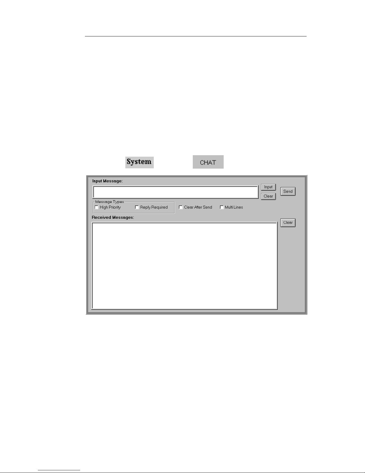
NIC Quick Reference Guide
73
7. Select an alarm type to display the Select All Alarms Sound
dialog box. The new WAV files appear in the dialog box. Only the
first 16 sounds will appear in the selection window. The sound
files that appear use the WAV file's name.
8. Select Apply. The Alarm Beep Definition window closes.
Using Chat
The Chat function can be used to send brief messages between Local
and Remote users on the same NIC.
To send a message:
1. Select and choose . The Chat screen appears.
2. Enter your message in the Input Message window.
If using the touch screen on a portable test set, select Input. A
keypad appears allowing you to enter the message. Select
Enter when done. The message appears in the Input Message
window.
If using the Remote Control Application to control a remote
test set, place your mouse cursor in to the Input Mes s age window and type the message.
Page 82

Document No. CO 004844K
74
NOTE
Pressing the Enter key on your keyboard will delete the message.
To avoid this, select Multi Lines before starting to type the
message.
In addition, if you have a long message, select Multi Lines so that
you can use the Enter key to keep your message within the Input
Message window.
3. You can assign a priority level to the message (High Priority), or
you can require that the recipient respond to the message (Reply
Required). Another user will not see the Chat message unless
High Priority or Reply Required is selected.
4. Select Send.
Using the Security Features
IMPORTANT
The Security option is not available unless you have Admin privileges.
This function allows you to view the following security information
about system users:
User Name
Permissions
– Read Only: Allows the user read-only privileges.
– Read/Write: Allows th e user to read and update information.
– Calibrate: Allows the user read and write privileges and the
ability to perform calibration procedures on the test set.
– Admin: Allows the user to perform network administrator
tasks such as calibrating, adding, deleting, and updating user
profiles.
Active: Displays “Yes” for user’s currently logged in to the test
set.
Current: Displays permissions of active users.
Default User: This column only appears on the local GUI and is
linked directly to the “User Login Required” setting on the System Misc screen. When User Login Required is not selected the
default user appears in the log in dialog box.
The Security function also enables a user with administrator privileges
to perform the following task s:
Page 83
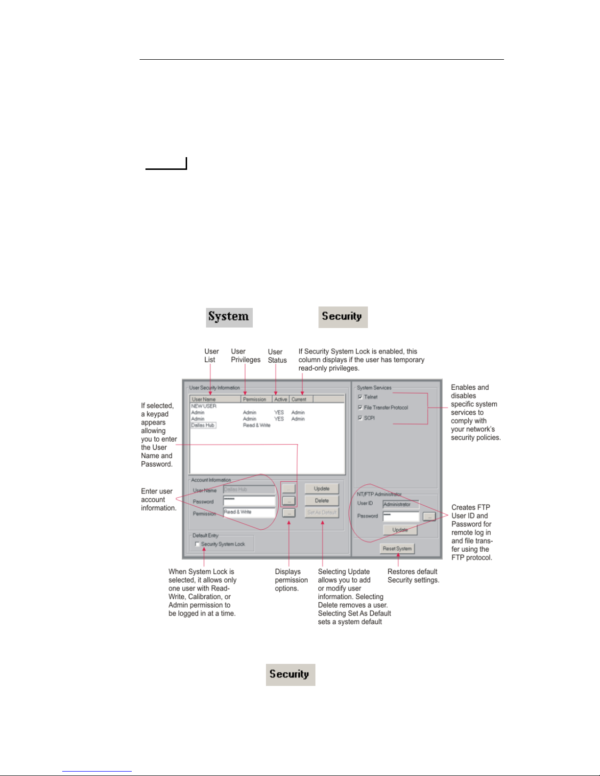
NIC Quick Reference Guide
75
Add, delete, and update a user profile
Enable and disable the Security System Lock feature
Establish a Default Login
Establish a Required Login
NOTE
Selecting Security System Lock check prevents other people from
logging onto the test set. If a user with Read and Write permissions is
already logged in, a window will appear giving you the option of
logging in with Read-Only permissions only. When the user logs on
with Read-Only permissions, all functionality will be disabled with
the exception of the online help and the About this product function.
Accessing the Security Function
1. Select and choo se . The Security screen
appears.
Adding a New User
1. Select and choose . The Security screen appears.
2. From the User Name column, select NEW USER.
Page 84
Document No. CO 004844K
76
3. Under Account Information, select next to the User Name
field. A keypad appears.
4. Enter the User Name.
5. Select next to the Password field. A keypad appears.
6. Enter a Password.
7. Select next to the Permissions field. The Select User
Permissions window appears.
8. Select one of the following user permissions:
– Read: Allows the user read-only privileges.
– Read/Write: Allows the user to read and update information.
– Calibrate: Allows the user read and write privileges and the
ability to perform calibration procedures on the unit.
– Admin: Allows the user to perform network administrator
tasks such as calibrating, adding, deleting, and updating user
profiles.
9. Select . The new user profile is added and appears on
the User List.
Updating a User Profile
1. Select and choose . The Security screen
appears.
2. From the User list, select the user profile to be updated. The user
name, password, and permissions appears in the Account box.
3. Select next to the field to be updated.
If Password was selected a keypad appears allowing you to
modify the current information. Press Enter when you are
done.
If Permissions was selected, the Select User Permissions win-
dow appears. Select the updated permissions that you wish to
apply.
4. When you are done updating the user's profile, select Update.
The updated information appears on the User List.
Page 85
NIC Quick Reference Guide
77
Deleting a User
1. Select and choo se . The Security screen
appears.
2. From the User Name co lumn, select the user you want to delete.
3. Select .
Establishing a Default Login
This function allows an administrator to establish a default login, which
results in the users not having to enter a user name and password each
time they use the test set.
NOTE
The default login function is only applicable from the NIC unit’s loacl
GUI. When connecting to a NIC via the Remote NIC application, a user
ID and password are alsway required.
To establish a default login:
1. Select and choo se . The Security screen
appears.
2. From the Users list box, select the User Name th at you wish to
make the default login.
3. Select . Under the Default User column, Yes appears,
indicating that the user has been established as default user.
To disable the User Login Required:
1. Select and choose . The Misc screen appears.
2. Under Local Settings, clear the User Login Requir ed check box.
A cleared check box indicates that the User Login Required is
disabled, and the unit will not prompt for a password on boot up.
3. Reboot the test set by selecting , and choose .
4. Select . The Reboot the Unit dialog box appears.
Page 86

Document No. CO 004844K
78
5. Select OK.
6. When the test set has rebooted, the Default User will automatically be logged into the local GUI, without being prompted to
enter a User Name or Password.
NOTE
If you do not wish to reset a Default Login user, there is no need
to continue to the next step.
7. If you wish to set another default user, log in as an Admin user
and repeat steps the steps above under the “Establishing a Default
Login”section.
To enable the User Login Required:
This function allows the user to enter a User Name and Password, each
time the test set is rebooted.
To establish a required login:
NOTE
The User Login Required check box is only available from
the NIC’s local GUI
.
1. Select and choose . The Misc screen appears.
2. Under Local Setting, enable the User Login Required check
box. A check appears in the check box indicating that a required
login has been established.
3. Reboot the test set by selecting , and choose .
4. Select . The Reboot the Unit dialog box appears.
5. Select OK.
6. When the test set has rebooted, a User Login box will appear
prompting the user to enter Username and Password before the
GUI can be displayed.
Page 87

NIC Quick Reference Guide
79
Enabling/Disabling Security System Lock
This function allows an administrator to enable a Security System Lock
that only allows one user with Read and Write permissions (this
includes Calibration and Admin users) to be logged in at a time. If a user
with Read and Write permissions is already logged in, a window will
appear giving you the option of logging in with Read-Only permissions
only. When the user logs in with Read-Only permissions, all functionality will be disabled with the exception of the online help and the About
this product function.
To enable Security System Lock:
1. Select and choo se . The Security screen
appears.
2. From Default Entry, select the Security System Lock check
box. A checked box indicates that the Security System Lock
function is enabled.
To disable Security System Lock:
1. Select and choo se . The Security screen
appears.
2. From Default Entry , clear the Security System Lock check box.
The cleared check box indicates that the Security System Lock
function is disabled.
Page 88

Document No. CO 004844K
80
Contact Technical Support
Digital Lightwave Technical Support representatives are available 24hours a day, 7 days a week, to help you.
Standard Service Hours
During Standard Service Hours (8:30 am to 5:30 pm EST, Monday
through Friday) please call:
1-877-929-4357 (Toll-Free in USA)
+1-727-475-1206 (International / local)
Extended Service Hours
During Extended Service Hours (anytime before or after standard service hours) please call the number below, and our 24-hour answeri ng
service will direct your call to an on-call tech support representative.
+1-727-448-1809 (USA / International)
Email Support
You may also contact our Technical Support representatives via email.
Emails received after 5:30pm EST will be replied to the next business
day.
 Loading...