

Digital Lightwave ASA 312 Calibration Manual

15550 Lightwave Drive • Clearwater, Florida 33760 • United States
T: 727.442.6677 • F: 727.442.5660 • Toll Free: 800.548.9283 or 877.275.3445
info@lightwave.co m • http://www.lightwave.com
ASA 312® NETWORK
INFORMATION COMPUTER
™
CALIBRATION MANUAL
April 2002
Document No. RF 002331D

ii Draft 1 — DLI Proprietary Information 4/15/02
Copyright Copyright © 2000-2002 Digital Lightwave, Inc.
All rights reserved.
This publication, or parts thereof, may not be reproduced in any form,
by any method, for any purpose. For conditions of use and permission
to use these materials for publication in othe r than the English
language, contact Digital Lightwave, Inc.
Digital Lightwave, Inc. reserves the right to revise and improve its
product as it sees fit. This publicat ion describes the st ate of thi s product
at the time of its publication and may not represent the product at all
times in the future.
Patent Information The ASA 312
®
Network Information Computer™ (NIC) described in
this publication may be protected by one or more patents on fil e wit h
the United States Patent Office.
Trademarks The rectangular logo is a registered trademark of Digital Lightwave,
Inc. in the United States and/or in other countries. Digital Lightwave;
Lightwave Management; Network Information Computer; Network
Access Agent; Optical Access Agent; Anywhere, Anytime, AnyBit; and
Technology to Reach Inside the Light are trademarks of Digital
Lightwave, Inc. for which application has been made. All other brands
and their products are trademarks or registered trademarks of their
respective owners.
Technical Support Technical Support is availabl e by call ing t oll fre e 1.8 77.929 .HELP (4357)
or 1.800.548.9283 24 hours/day, 7 days/week.
Return Shipping
Instructions
If it is necessary to return the unit, obtain a Return Material
Authorization (RMA) number and Return Shipping Address by
contacting Technical Support between 8:30 a.m. and 6:30 p.m. EST,
Monday through Friday.
Please enclose a letter that br iefly describes the reason for returni ng the
unit and include the following informa ti on:
• Unit Serial Number
• Customer Name and Shipping Address
• Customer Contact Name and Telephone Number
• Secondary Customer Contact Name and Telephone Number
• Customer Supplied Purchase Order Number (if applicable)

Draft 1 — DLI Proprietary Information 4/15/02 iii
If the original shipping container (box) is available, place the unit (and
letter that describes the reason for the return) into the canvas carry bag, and
pack it into the original Digital Lightwave, Inc. shipping container . Do not
include personal items such as jumper cords or connectors. Digital
Lightwave, Inc. will not be responsible for these items. Use the original
foam inserts to protect all six sides of the unit.
Securely seal the shipping container, and mark FRAGILE on the cont ainer t o
ensure careful handling.
Include the RMA number on the outside of the shipping container.
If the original shipping container is not avai lable, (a) an ASA 312 shipping
container (Part Number ASA-BOX) can be purchased fr om Digital Lightwave,
or (b) pack the unit (and letter that describes the reason for the return) into
the canvas carry bag, and use the foll owing general instr uctions to repack the
unit using commercially available material s:
– Use a strong shipping container, similar to the original ASA 312 ship-
ping box. Verify that the substitute container is rated at 350 lbs. per
square inch pressure durable.
– Make sure that the unit is satisfactorily protected by using a layer of
ESD Protected short absorbing foam material. The foam p adding
must be 3- to 4-inches in thicknes s (70- to 100-mm) and applied to all
six sides of the unit to provide adequate protection. Make sur e that
the canvas bag and unit cannot move or shift wi thin the container.
– Securely seal the shi pp in g c ontai ne r, a nd mar k FRAGILE on the con-
tainer to ensure careful handling.
– Include the RMA number on the outside of the shipping container.
Contact Technical Support for the Repair Department’s Return
Shipping Address.
When service is complete, your unit will be returned t o you postage paid if the
shipment is within the United States. You are responsible for paying all
shipping charges, duties, taxes, and other charges for products returned to
Digital Lightwave, Inc. from any location within or outside of the United
States.

iv Draft 1 — DLI Proprietary Information 4/15/02
GENERAL SAFETY
GUIDELINES
The following safety precautions are provided to avoid injury and
prevent damage to this product or any products connected to it during
normal operation. Only qualified maintenance personnel should
perform service procedures.
Use Proper Power Cord To avoid fire hazard, use only the power cord specified for this
instrument.
Avoid Electric Overload This unit is designed to be powered from 90–132 and 180–260 VAC,
47-63 Hz, 60 watts. To avoid electric shock, fire hazard, or damage to
the instrument, do not apply a higher voltage.
Ground the Instrument The ASA 312 is grounded through the grounding conductor of the
power cord. To avoid electric shock, the grounding conductor must be
connected to earth ground. Before making connections to the input or
output terminals of the instrument, ensure that the product is properly
grounded.
Do Not Operate in
Hazardous Conditions
To avoid injury or fire hazard, do not operate this i nstrument in wet,
damp, or other hazardous condition. Do not operate thi s instrument in
an explosive atmosphere.
Eye Protection Users should never stare into unterminated connectors or broken
fibers. In addition, fiber cables and interfaces should always be
handled as if they were emitting laser light. Always leave protective
covers on optical connectors to prevent damage and prevent laser
emissions.
CAUTION
Use of controls or adjustments or procedures other than those specified herein may
result in hazardous radiation exposure.
Replacing the Battery The ASA 312 uses a lithium battery located in the service access area
not accessible to customers. To avoid damaging the unit, do not under
any circumstances attempt to replace the lithium battery. Return the
unit to Digital Lightwave, Inc. for battery replacement.
WARNING
Danger of explosion exists if the battery is replaced incorrectly. Do not, under
any circumstances, attempt to replace the lithium battery.
➤
➤
Draft 1 — DLI Proprietary Information 4/15/02 v
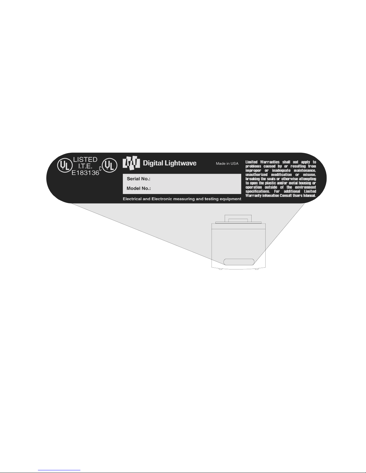
Serial No. / Model No.
Label
The following label is located on the rear of the ASA 312.
vi Draft 1 — DLI Proprietary Information 4/15/02
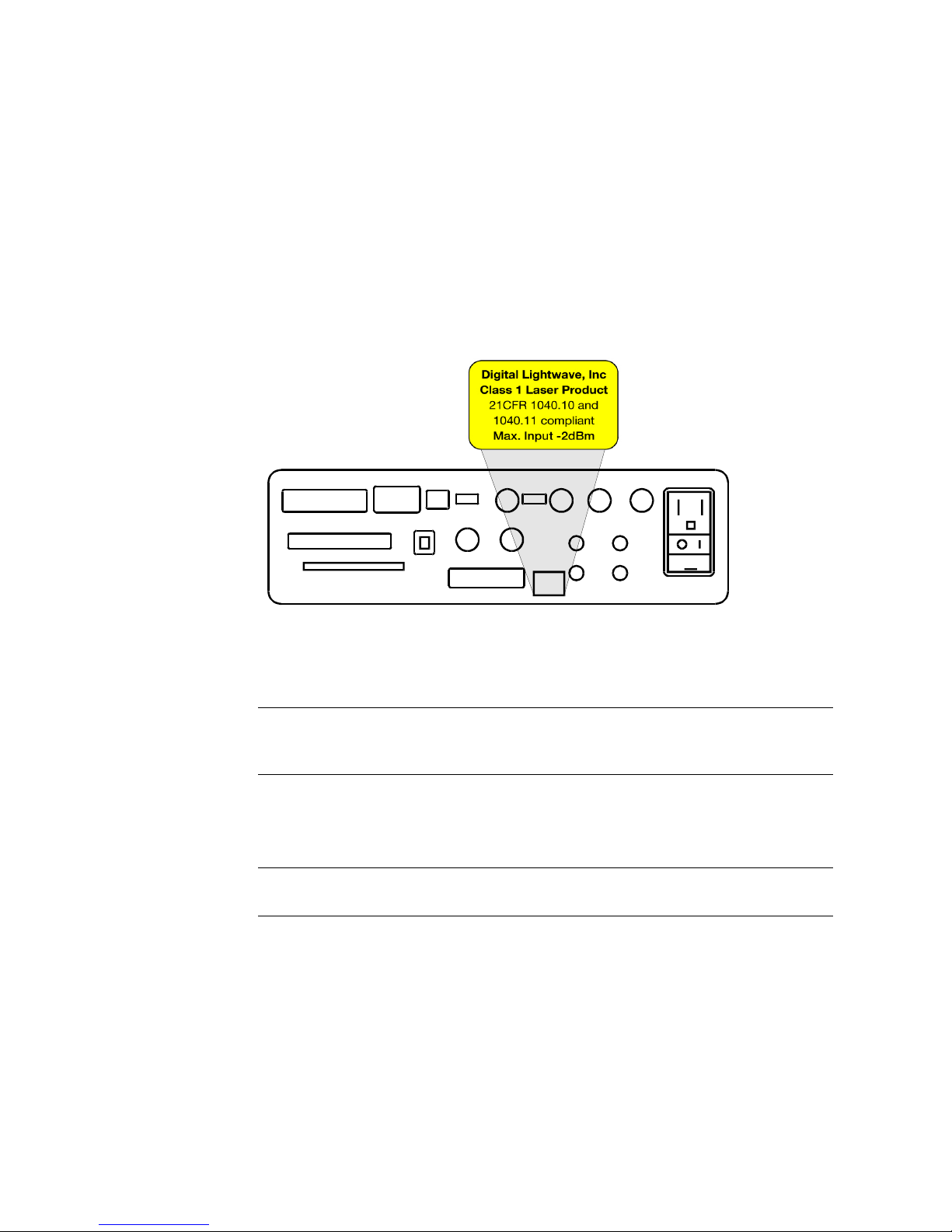
Class 1 Laser Label The following label is located on the ASA 312’s Connector Panel.
ASA 312 Lasers
The CDRH report accession number for the ASA 312 is 9612361.
Laser Wavelength Class
Typical Normal
Operation Output
Power*
OC-1/12 1310 nm Class 1 30
µW
OC-1/12 1550 nm Class 1 29 µW
OC-48 1310 nm Class 1 25 µW
OC-48 1550 nm Class 1 22 µW
* Laser output power measurements are measured during normal operation at 20 cm from
meter probe to laser objective lens.

Draft 1 — DLI Proprietary Information 4/15/02 vii
Contents
1 ASA 312 Calibration Overview
Introduction . . . . . . . . . . . . . . . . . . . . . . . . . . . . . . . . . . . . . . . . . . . . 1-1
Calibration Overview. . . . . . . . . . . . . . . . . . . . . . . . . . . . . . . . . . . . . 1-2
Required Equipment. . . . . . . . . . . . . . . . . . . . . . . . . . . . . . . . . . . 1-2
Measurements . . . . . . . . . . . . . . . . . . . . . . . . . . . . . . . . . . . . . . . 1-3
Calibration Commands. . . . . . . . . . . . . . . . . . . . . . . . . . . . . . . . . . . . 1-4
Frequency Adj (0-255). . . . . . . . . . . . . . . . . . . . . . . . . . . . . . 1-4
DS1 Range . . . . . . . . . . . . . . . . . . . . . . . . . . . . . . . . . . . . . . . 1-4
DS1 Pos Peak. . . . . . . . . . . . . . . . . . . . . . . . . . . . . . . . . . . . . 1-4
DS1 Neg Peak . . . . . . . . . . . . . . . . . . . . . . . . . . . . . . . . . . . . 1-4
DS3 Pos Peak. . . . . . . . . . . . . . . . . . . . . . . . . . . . . . . . . . . . . 1-5
DS3 Neg Peak . . . . . . . . . . . . . . . . . . . . . . . . . . . . . . . . . . . . 1-5
STSX-1 Pos Peak. . . . . . . . . . . . . . . . . . . . . . . . . . . . . . . . . . 1-5
STSX-1 Neg Peak . . . . . . . . . . . . . . . . . . . . . . . . . . . . . . . . . 1-5
Optical Power Range . . . . . . . . . . . . . . . . . . . . . . . . . . . . . . . 1-5
Optical Power. . . . . . . . . . . . . . . . . . . . . . . . . . . . . . . . . . . . . 1-5
OC48 Optical Power . . . . . . . . . . . . . . . . . . . . . . . . . . . . . . . 1-5
Save Calibration. . . . . . . . . . . . . . . . . . . . . . . . . . . . . . . . . . . 1-5
Change Password. . . . . . . . . . . . . . . . . . . . . . . . . . . . . . . . . . 1-5
Before You Calibrate the ASA 312 . . . . . . . . . . . . . . . . . . . . . . . . . . 1-5
2 DS1 and Frequency Adjustment Calibration
Overview . . . . . . . . . . . . . . . . . . . . . . . . . . . . . . . . . . . . . . . . . . . . . . 2-1
Frequency Adjustment . . . . . . . . . . . . . . . . . . . . . . . . . . . . . . . . . . . . 2-1
Required Equipment. . . . . . . . . . . . . . . . . . . . . . . . . . . . . . . . . . . 2-1
Hardware Setup . . . . . . . . . . . . . . . . . . . . . . . . . . . . . . . . . . . . . . 2-1
ASA 312 Settings. . . . . . . . . . . . . . . . . . . . . . . . . . . . . . . . . . 2-2
Adjusting the Frequency . . . . . . . . . . . . . . . . . . . . . . . . . . . . . . . 2-2
DS1 Positive and Negative Peak Settings . . . . . . . . . . . . . . . . . . . . . 2-3
Required Equipment. . . . . . . . . . . . . . . . . . . . . . . . . . . . . . . . . . . 2-3
Hardware Setup . . . . . . . . . . . . . . . . . . . . . . . . . . . . . . . . . . . . . . 2-4
ASA 312 Settings. . . . . . . . . . . . . . . . . . . . . . . . . . . . . . . . . . 2-4
Oscilloscope Settings. . . . . . . . . . . . . . . . . . . . . . . . . . . . . . . 2-4
Function Generator Settings. . . . . . . . . . . . . . . . . . . . . . . . . . 2-5
Calibrating DS1 . . . . . . . . . . . . . . . . . . . . . . . . . . . . . . . . . . . . . . 2-5

Contents Document No. RF 002331D
viii Draft 1 — DLI Proprietary Information 4/15/02
3 DS3 Calibration
Overview . . . . . . . . . . . . . . . . . . . . . . . . . . . . . . . . . . . . . . . . . . . . . . 3-1
DS3 Terminated Positive and Negative Peak Settings . . . . . . . . . . . 3-1
Required Equipment. . . . . . . . . . . . . . . . . . . . . . . . . . . . . . . . . . . 3-1
Hardware Setup . . . . . . . . . . . . . . . . . . . . . . . . . . . . . . . . . . . . . . 3-1
ASA 312 Settings. . . . . . . . . . . . . . . . . . . . . . . . . . . . . . . . . . 3-2
Oscilloscope Settings. . . . . . . . . . . . . . . . . . . . . . . . . . . . . . . 3-2
Calibrating DS3 Terminated . . . . . . . . . . . . . . . . . . . . . . . . . . . . 3-3
DS3 Monitor Positive and Negative Peak Settings . . . . . . . . . . . . . . 3-3
Required Equipment. . . . . . . . . . . . . . . . . . . . . . . . . . . . . . . . . . . 3-3
Hardware Setup . . . . . . . . . . . . . . . . . . . . . . . . . . . . . . . . . . . . . . 3-4
ASA 312 Settings. . . . . . . . . . . . . . . . . . . . . . . . . . . . . . . . . . 3-4
Oscilloscope Settings. . . . . . . . . . . . . . . . . . . . . . . . . . . . . . . 3-4
Calibrating DS3 Monitor . . . . . . . . . . . . . . . . . . . . . . . . . . . . . . . 3-4
Hardware Setup . . . . . . . . . . . . . . . . . . . . . . . . . . . . . . . . . . . 3-4
90 mV Peak Adjustment . . . . . . . . . . . . . . . . . . . . . . . . . . . . 3-5
DS3 High Settings . . . . . . . . . . . . . . . . . . . . . . . . . . . . . . . . . . . . . . . 3-6
Required Equipment. . . . . . . . . . . . . . . . . . . . . . . . . . . . . . . . . . . 3-6
Hardware Setup . . . . . . . . . . . . . . . . . . . . . . . . . . . . . . . . . . . . . . 3-6
ASA 312 Settings. . . . . . . . . . . . . . . . . . . . . . . . . . . . . . . . . . 3-7
Oscilloscope Settings. . . . . . . . . . . . . . . . . . . . . . . . . . . . . . . 3-7
Calibrating DS3 High. . . . . . . . . . . . . . . . . . . . . . . . . . . . . . . . . . 3-8
4 STSX-1 Calibration
STSX-1 Positive and Negative Peak Settings . . . . . . . . . . . . . . . . . . 4-1
Required Equipment. . . . . . . . . . . . . . . . . . . . . . . . . . . . . . . . . . . 4-1
Hardware Setup . . . . . . . . . . . . . . . . . . . . . . . . . . . . . . . . . . . . . . 4-1
ASA Settings . . . . . . . . . . . . . . . . . . . . . . . . . . . . . . . . . . . . . 4-2
Oscilloscope Settings. . . . . . . . . . . . . . . . . . . . . . . . . . . . . . . 4-2
Calibrating STSX-1 . . . . . . . . . . . . . . . . . . . . . . . . . . . . . . . . . . . 4-2
5 Optical Power Calibration
Calibrating Optical Power . . . . . . . . . . . . . . . . . . . . . . . . . . . . . . . . . 5-1
Required Equipment. . . . . . . . . . . . . . . . . . . . . . . . . . . . . . . . . . . 5-1
Before You Begin . . . . . . . . . . . . . . . . . . . . . . . . . . . . . . . . . . . . 5-1
Optical Power Calibration for a Single Laser
or Dual Laser ASA 312 . . . . . . . . . . . . . . . . . . . . . . . . . . . . . . . . 5-1
Initial Optical Power Measurement . . . . . . . . . . . . . . . . . . . . 5-2
Setting Range 1 . . . . . . . . . . . . . . . . . . . . . . . . . . . . . . . . . . . 5-4
Setting Range 2 . . . . . . . . . . . . . . . . . . . . . . . . . . . . . . . . . . . 5-5
Setting Range 3 . . . . . . . . . . . . . . . . . . . . . . . . . . . . . . . . . . . 5-6
Setting Range 4 . . . . . . . . . . . . . . . . . . . . . . . . . . . . . . . . . . . 5-7
Changing the Laser Type for a Dual Laser ASA 312 . . . . . . . . . 5-8

ASA 312 Network Information Computer Calibration Manual Contents
Draft 1 — DLI Proprietary Information 4/15/02
ix
Calibrating Optical Power for OC-48 . . . . . . . . . . . . . . . . . . . . . 5-8
OC-48 Reference Value. . . . . . . . . . . . . . . . . . . . . . . . . . . . . 5-8
First OC-48 Optical Power Measurement . . . . . . . . . . . . . . . 5-8
Second OC-48 Optical Power Measurement . . . . . . . . . . . . . 5-9
6 Saving Calibration Values and Passwords
Saving New Calibration Values. . . . . . . . . . . . . . . . . . . . . . . . . . . . . 6-1
Changing the Password . . . . . . . . . . . . . . . . . . . . . . . . . . . . . . . . . . . 6-1
A ASA 312 Connector Panel
Index
. . . . . . . . . . . . . . . . . . . . . . . . . . . . . . . . . . . . . . . . . . . . Index-1

Contents Document No. RF 002331D
x Draft 1 — DLI Proprietary Information 4/15/02

xi
Preface
About This Guide
This guide describes how to calibrate the ASA 312 Network Information Computer. Use this guide to obtain a basic und erstan ding of th e ASA 312’s calibr ation
procedures.
This guide is intended for personnel respo nsible for maintaining and calibrating
the ASA 312. It is assumed that you have a basic understanding of the following:
■ ASA 312 Network Information Computer
■ Oscilloscopes
NOTE
➤
For ASA 312 configuration and operation information, see the ASA 312 Network Information Computer User’s Guide, Document No. RF 002470 or the
ASA 312 Network Information Computer and Remote Access Manager User’s
Guide, CO 003202.
Organization of This Guide
This guide is organized as follows:
➤
Chapter Description
Chapter 1 ASA 312 Calibration Overview. This chapter pro-
vides a brief description of the calibration process.
Chapter 2 DS1 and Frequency Calibration. This chapter
describes the equipment and procedures required
to perform DS1 calibration.
Chapter 3 DS3 Calibr ation. This chapter describes the equip-
ment and procedures required to perform DS3 calibration.
Chapter 4 STSX-1 Calibration. This chapter describes the
equipment and procedures required to perform
STSX-1 calibration.
Chapter 5 Optical Power Calibration. This chapter describes
how to perform single laser and dual laser optical
calibration for OC-1, OC-3, OC-12, and OC-48
configurations.
Chapter 6 Saving Calibration Values and Passwords. This
chapter describes how to save new calibration values, and how to save and change new calibration
passwords.

Preface Document No. RF 0023331D
xii
Document Conventions
Throughout this guide, the following typographical conventions are used:
■ This typeface indicates a filename or pathname. It is also used to reference a
chapter or section within this guide, or another document. For example:
Save the new calibrat i on val ues fo llowi ng the procedures i n the Saving New
Calibration Values section.
■ This typeface is used to emphasize text. For example:
If you have a single laser ASA 312, this concludes the Optical Calibration
for an ASA 312 with OC-1, OC-3, or OC-12 optical interfaces.
■ This typeface indicate s a command name, menu selection, butt on, or icon. For
example:
Press the Optical Power Range command and select 1.
Related Document
Related document:
■ ASA 312 Network Information Computer and Remote Access Manager User’s
Guide, CO 003202.
Also review Software Release Update Notes for new features that may not yet be
described in the User’s Guide.
Appendix A ASA 312 Connector Panel. This appendix illus-
trates the ASA 312 connector panel.
Chapter Description

Draft 1 — DLI Proprietary Information 4/15/02 1-1
1
ASA 312 Calibration Overview
Introduction
The ASA 312 Network Information Computer is a portable test set capable of
operating at rates from DS0 through OC-48. Periodic calibration of the ASA 312
is required to maintain its accuracy and precision. This document describes the
equipment and procedures necessary to calibrate the ASA 312’s voltage, power,
and frequency measurements.
Although the ASA 312 may be calibrated at any time, it is recommend that
calibration procedures be performed only during routine scheduled maintenance.
(Digital Lightwave recommends a calibration interval of two years.) This avoids
any accidental changes to the unit’s default and calibration settings.
The ASA 312’s Touch Screen user interface provides convenient access to
calibration commands. After calibration is complete, a system password is
required to save the new calibration parameters. This feature prevents
unauthorized or unintentional calibration changes to the unit’s default and
operational settings. Changes to the ASA 312’s calibration settings will only be
saved with user verification and authorization.
This document assumes that you are familiar with the ASA 312’s operations and
capabilities. For information regarding the unit’s operations, functions and te sting
capabilities, refer to the user’s guide that is supplied with your unit.
Due to the technical aspects of calibrating the ASA 312, it is recommended that
you read through this manual prior to calibrating the unit. If you need assistance
calibrating your instrument, or have questions concerning the operations or
service of the ASA 312, please contact your Digi tal Li ghtwave Sales or T echnical
Support representative.
Technical support is available by call 1-877-929-HELP (4357) or
1-800-548-9283.

ASA 312 Calibration Overview Document No. RF 002331D
1-2 Draft 1 — DLI Proprietary Information 4/15/02
Calibration Overview
The ASA 312 uses a soft calibration method to maintain the accuracy of several
measurement factors.
To perform calibration of the unit, you will attach several different scopes,
generators, meters, and cables to the ASA 312 to measure, and if necessary adj ust,
electrical and optical measurement parameters of the ASA 312.
A typical calibration scenario involves:
■ Attaching the proper ASA 312 output and input to external measuring
devices
■ Entering the correct parameters into the measuring devices
■ Configuring the ASA 312 for the appropriate measurement
■ Recording the proper measurement
■ Entering the adjusted measurement into the ASA 312
■ Saving the new measurement
The remainder of this document describes the equipment required to complete a
proper calibration of the ASA 312 and the procedures for setting up, recording,
and saving measurements to the ASA 312.
A complete calibration of the ASA 312 involves measuring the following factors:
■ Frequency calibration
■ DS1 calibration
■ DS3 calibration
■ STSX-1 calibration
■ Optical power calibration
Required Equipment
The following equipment is required to perform a complete calibration of the
ASA 312:
NOTE
➤
For ASA 312 operation, refer to the ASA 312 Network Information Computer
User’s Guide or the ASA 312 Network Information Computer and Remote
Access Manager User’s Guide.
For setup and operation procedures for the remaining equipment, refer to the
user documentation for each device.
■ An ASA 312 Network Information Computer
■ A BNC T-connector
■ Two 2-ft., 75 ohm coaxial cables with male BNC connectors
■ Two 3-ft. single-m ode, fiber optic cables
➤

ASA 312 Network Information Computer Calibration Manual ASA 312 Calibration Overview
Draft 1 — DLI Proprietary Information 4/15/02
1-3
■ A 3-ft., 100 ohm BNC-to-Bantam cable
This is a custom cable that can be ordered directly from Digital
Lightwave (Part Number 002727). It is used for Frequency Adjustment
calibration.
■ A 3-ft., 75 ohm BNC-to-Bantam cable with 1.0 µF capacitor
This is a custom cable that can be ordered directly from Digital
Lightwave (Part Number 001901). It is used for DS1 calibration.
■ An 8-digit or greater frequency counter with a frequency rating of 225
MHz or greater
(Digital Lightwave uses an HP53131A Universal Counter.)
■ A function generator
(Digital Lightwave uses a Tektronics CFG253 3-MHz Function
Generator or equivalent device.)
■ A digital oscilloscope
(Digital Lightwave uses a Tektronics TDS380 Digitizi ng Osci l lo scope or
equivalent device.)
■ A 75 ohm attenuator
(Digital Lightwave us es a JFW Indu stries Model 75DR-003 or equival ent
device.)
■ A variable optical attenuator
(Digital Lightwave uses a Laser Precision DB2910 or equivalent device.)
■ An optical power meter
(Digital Lightwave uses a Lase r Precisi on LP-5000 or equivalent de vice.)
■ A fiber optics cleaning kit
Measurements
The ASA 312 uses a soft-calibration method to adjust parameters for the
following measurements:
■ Frequency calibration
■ DS1 calibration
■ DS3 calibration
■ STSX-1 calibration
■ Optical power calibration
 Loading...