

Page 1
Digital Lighting Systems, Inc.
OPTIMA-DS Series
DMX CHASER/CROSS-FADER
Controllers
OPTIMA-DS
MODE
RUN
RATE
MAX.
LEVEL
MIN.
LEVEL
USER MANUAL
Lighting Animation Controller
FADE
AUTO
STOP
BLK.
OUT
Digital Lighting Systems
Miami, Fl. USA
digitallighting.com
DIM1
DIM2
DIM3
DIM4
MODEL NUMBERS
! OPTIMA-DS
! OPTIMA-DS2
! OPTIMA-DS2C
OSUM
Rev. A 06-01
Page 2
Digital Lighting Systems
OPTIMA-DS
DMX 3 - 8 Channel Controllers
User's Manual - Page 1
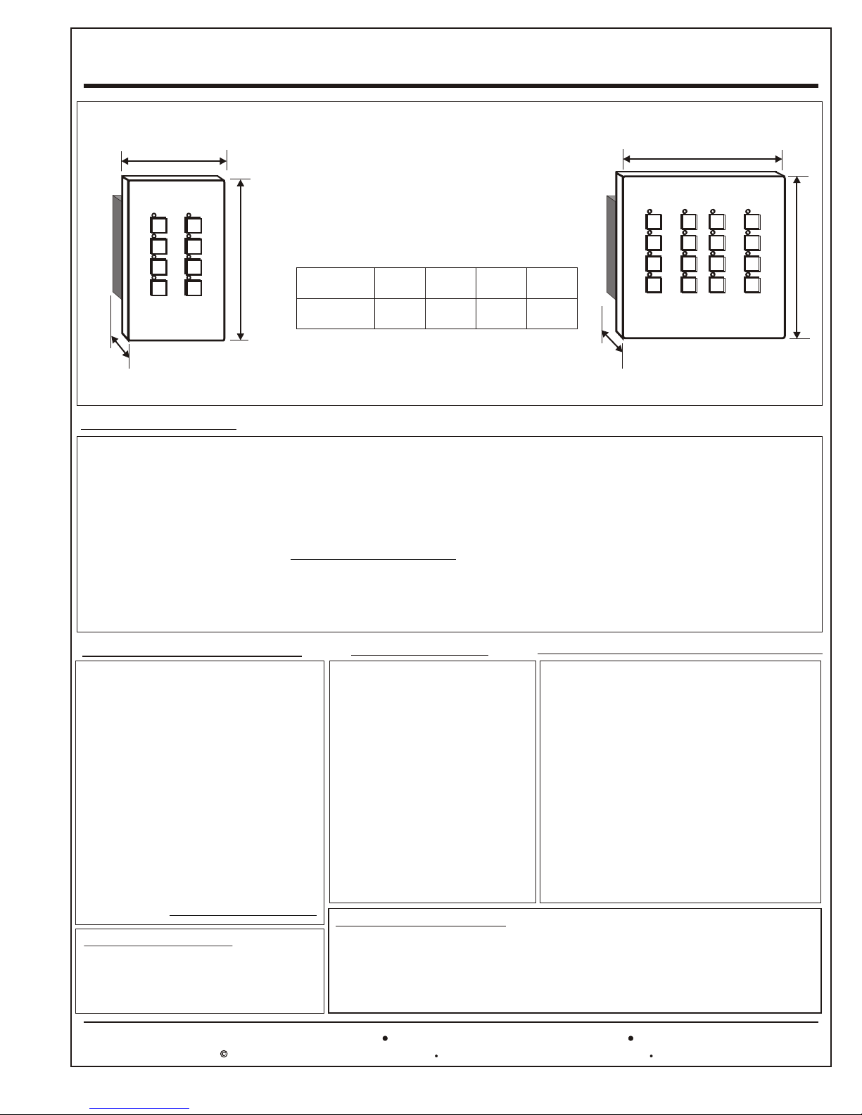
Single-Gang Models
W
Double-Gang Models
W
Maximum Outside Dimensions
HDH
OPTIMA-DS2
MODEL
OPTIMA-DS2
OPTIMA-DS2-C
OPTIMA-DS
DEPTH (D) includes circuit board with components
WIDTH HEIGHT DEPTH
2.700”
067 mm
4.600"
117 mm
4.600"
117 mm
4.600"
117 mm
1.650"
042 mm
1.650"
042 mm
GANG
Single
Double
D
H
OPTIMA-DS
OPTIMA-DS2-C
INTRODUCTION
The OPTIMA DS is a four-channel 16-pattern lighting cross-fader with master and individual channel dimming. Controls
for adjusting the off-level and fade rate are also standard on the unit. This new design employs the latest electronic
technology and presents a control panel with a sleek modern look and simple to use controls. Added features include a
standard DMX-512 output. When in dynamic mode, the OPTIMA-DS creates dazzling light shows from its built-in
repertoire of lighting animation sequences. In static mode, the OPTIMA-DS acts as a four-circuit dimmer with a black-out
control. The OPTIMA DS can also work in a traditional chase mode. In short, whether your lighting project requires sharp
light sequencing or a more subtle cross-fade mixing of colors, the OPTIMA- DS provides you with a perfect solution. The
DMX-512 compatibility makes the OPTIMA-DS a perfect and inexpensive solution for retrofit applications by working with
existing DMX-512 dimmers. The OPTIMA-DS2 models do not have individual channel dimmers and mount in a singlegang masonry box. The OPTIMA DS requires a double-gang masonry box.
OPTIMA-DS FEATURES
6 Economical.
6 4-Color / 4-Channel Sequencing.
6 16 Exciting Light / Color Patterns.
6 Cross-Fade and Chase Modes.
6 Static 4-Ch. Dimmer Mode with Master.
6 Automatic Pattern Change Mode.
6 Single Pattern Select Mode.
6 Independently Adjustable Chase Rate.
6 Independently Adjustable Fade Rate.
6 Blackout Switch.
6 Master Off-Level Adjustment.
6 Settings are saved in Nonvolatile Memory.
6 Simple Pushbutton Operation.
6 LED Mode Indicators.
6 Custom Patterns Available.
6 Available in 3, 4 ,5, 6, 7 & 8 Channels.
OPTIMA DS2 & DS2-C
Same features as DS except no individual
channel dimming. They mount in a single-gang
masonry box. DS2-C is a chase only version
with no fade option.
7588 NW 8th Street, Miami, Fl. 33126
APPLICATIONS
! Architectural & Decorative
Lighting.
! Landscape Lighting.
! Structure Lighting.
! Pond and Fountain Lighting.
! Museums and Art Galleries.
! Movie Theaters.
! Theme Parks.
! Fair Rides.
! Point of Sale Displays.
! Christmas Trees and Displays.
! Electric Sign Animation.
! Entertainment and Club
Lighting.
PD408-DMX DIMMER PACK
The OPTIMA DS requires an external dimmer pack with a DMX cable. Any DMX-512 compatible
dimmer may be used. Digital Lighting Systems, Inc. manufactures high quality low cost DMX-512
dimmer packs. The PD408-DMX is an excellent companion to the OPTIMA DS. It can drive four
960 Watt 120 VAC loads at 50 and 60Hz. 12/24/220 VAC versions are available.
Tel: 305-264-8391 Fax: 305-261-6637or 1-877-264-8391
Specifications are subject to change without notice.Copyright 2001 Digital Lighting Systems, All rights Reserved
Physical and Electrical Specifications
Back Plate: Metal Construction.
Dimensions: See Table Above.
Power: Max. 80 mA at 10 VAC-50/60 Hz.
Data Output: RS485 Compliant.
Output Drive: 256 1/8 DMX Loads.
Data Format: Standard DMX-512 Protocol.
Data Retention: 10 years, no batteries required.
ESD Protection: 15 KV on data input and output.
DS Port: Standard 5-pin XLR Female.
DS2 Port: 0.1" c-c, 8 Position Male Header.
Available with pigtail DMX-512
Adapter.
Printed in U.S.A.
OptimaSpec
7/01
Page 3
Digital Lighting Systems
OPTIMA-DS
DMX 3 - 8 Channel Controllers
User's Manual - Page 2
Deep Metal Masonry Box
(by others)
Masonry Box
Must Be
Properly
Grounded
Network Bus
2-1/2"
64 mm
Inside Clearance
75 mm
2-15/16"
Pigtail DMX-512 Adapter
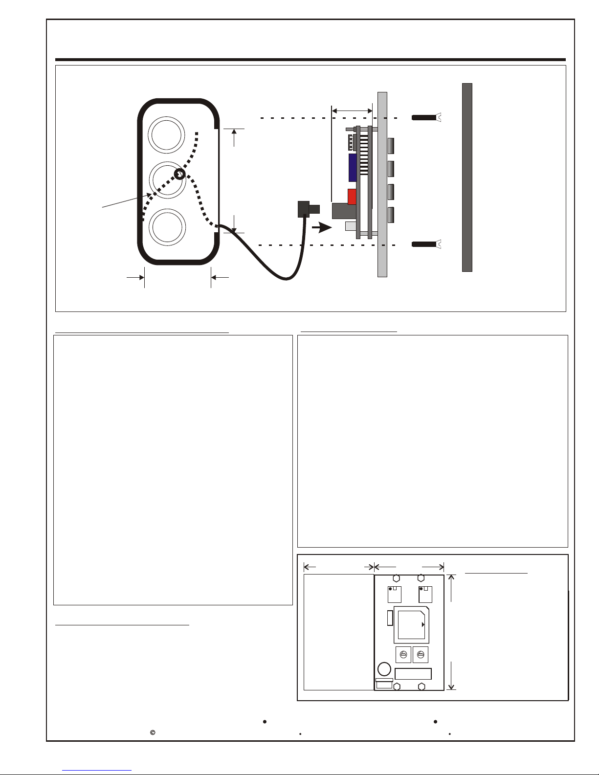
Mounting requirements
! The OPTIMA DS mounts in double-
gang deep masonry box or may be
ordered in a table top aluminum
enclosure. The Female XLR connector
comes mounted on the side of the
enclosure. The OPTIMA DS2 is only
available for mounting in a single-gang
masonry box.
! Both types of masonry boxes must have
a minimum depth of 2-1/2" and a
minimum inside height of 2-15/16" to
allow clearance for printed circuit board.
Circuit
Height
1.400"
36 mm
Screws (2)
6-32 x 1"
Typical Cover
J8FXLR5-L
Wiring Notes
! All wiring between the OPTIMA and dimmer packs
is low voltage (NEMA Class 2) and must be a
shielded twisted pair cable. Refer to the OPTIMA
User's Manual for more details.
! Standard industry DMX-512 cables may be used
with the OPTIMA.
! Do not run DMX cable in the same conduit with
non-class 2 circuits.
! The OPTIMA is supplied with an external low
voltage wall adapter.
! Power for the adapter may be on a different power
phase from power supplying the DMX-512 dimmer
packs or fixtures.
! Installation must conform to local and/or NEC code
requirements.
(See above illustration.)
! Use Grounded metal boxes only.
Ordering Information
OPTIMA-DS: Cross-Fader/Chaser/4-Channel
Dimming Controller, 2-G size.
OPTIMA-AE: Alum.Enclosure for OPTIMA DS.
OPTIMA-DS2: Cross-Fader/Chaser 1-G size.
OPTIMA-DS2C: Chaser 1-G size.
J8FXLR5-L: Pigtail DMX-512 XLR Adapter. L=
(Length in feet).
7588 NW 8th Street, Miami, Fl. 33126
1.810” - 46 mm
46 mm
8
Additional Circuitry
For 2-G Panels
1.810"
2
4
1
1
1
2
0
0
3
F
F
4
E
E
5
6
D
D
7
C
S2
5
6
C
8
B
B
9
A
A
Tel: 305-264-8391 Fax: 305-261-6637or 1-877-264-8391
Specifications are subject to change without notice.Copyright 2001 Digital Lighting Systems, All rights Reserved
Circuit Legend
1 Microprocessor.
3
2
3
4
5
6
7
S1
8
9
7
2 Nonvolatile Memory.
3 Communications Chip.
4 Quartz Crystal.
5 Power Supply Capacitor.
6 Voltage Regulator.
7 Output Port.
2.825" - 72 mm
8 Buttons 9-16 Keypad.
S1 Fade Rate Selector.
S2 Special Mode Selector.
Printed in U.S.A.
OptimaSpec
7/01
Page 4
Digital Lighting Systems
OPTIMA-DS
User's Manual - Page 3
A - General Information
DMX 3 - 8 Channel Controllers
The OPTIMA Series controllers use low-power electronic components and do not not directly connect to high
voltage supply or electric loads. They are powered by an external low-voltage transformer. The loads connect to a
separate DMX-512 compatible dimmer pack(s). The OPTIMA controls the outputs of the dimmer pack(s) by
sending a series of digital dimming levels over a low voltage cable. Several DMX dimmer packs may be
connected to the same control cable in a daisy-chain configuration. The DMX information is received by all
dimmers and each pack extracts and uses the portion of the information that is intended for it. This is
accomplished by setting each dimmer pack to a different DMX address by way of address selectors. It is possible
to have several dimmer packs set to the same address when controlling loads that exceeds the dimmer’s output
capacity. Loads may be broken into smaller sections and still be controlled as a single load by any particular DMX
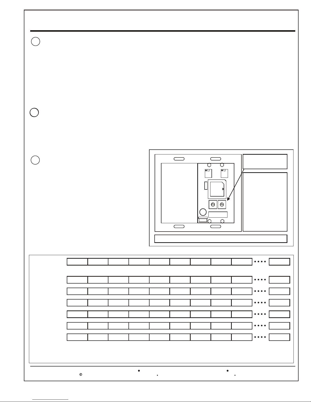
B - Number of Channels Configuration
The OPTIMA Series controllers may control 3 to 8 channels of DMX. They must be configured to the correct
number of channels as required by the application. There are two hexidecimal selectors on the back of the unit.
The selector marked S1 is used to slect the number of channels controlled. Figure 1 illustrates how to select the
desired number of channels.
C - OPTIMA DMX Output
The information sent by the OPTIMA is in
accordance with the DMX-512 standard control
protocol. When set to 3 or 4 channels, the
OPTIMA sends control information over the
first 4 DMX addresses. When set to between 5
and 8 channels, it uses the first 8 DMX
addresses. All remaining addresses, up to 512,
are sent a DMX off-level. Figure 2 below
shows the various DMX outputs generated by
the OPTIMA according to the number of
channels setting.
DMX OUTPUT
3 Ch. Values
4 Ch. Values
5 Ch. Values
Channel 1 Channel 2 Channel 3 Channel 4 Channel 5 Channel 6 Channel 7 Channel 8 Channel 9 Channel 512
Level 1
Level 1
Level 1
Level 2
Level 2
Level 2
Level 3
Level 3
Level 3
1
1
2
2
0
0
3
3
F
F
4
4
E
E
5
5
6
6
D
D
7
7
C
S2
C
S1
8
8
B
B
9
9
A
A
Fig. 1 OPTIMA - number of Channels Configuration
X 0 0 0 0 0
Level 4
Level 4
0 0 0 0 0
Level 5
X X X
Selector S1
Number of Channels
Using a small tip
screw driver, rotate
the shaft and
position the arrow
at the desired
number. Valid
range: from 3 to 8
Channels.
0
0
0
0
6 Ch. Values
7 Ch. Values
8 Ch. Values
Level 1
Level 1
Level 1
Level 2
Level 2
Level 2
Key: Level = Value sent depending on pattern X = Unpredictable Value 0 = Off Level
FIG. 2 - OPTIMA DMX OUTPUT FORMAT ACCORDING TO NUMBER OF CHANNELS SETTING
7588 NW 8th Street, Miami, Fl. 33126
Level 3
Level 3
Level 3
Level 4
Level 4
Level 4
Level 5
Level 5
Level 5
Tel: 305-264-8391 Fax: 305-261-6637or 1-877-264-8391
Specifications are subject to change without notice.Copyright 1999 Digital Lighting Systems, All rights Reserved
Level 6
Level 6
Level 6
X X
Level 7
Level 7 Level 8
X
0
0
0
Printed in U.S.A.
0
0
0
OSUM
Rev. A 09/01
Page 5
Digital Lighting Systems
OPTIMA-DS
User's Manual - Page 4
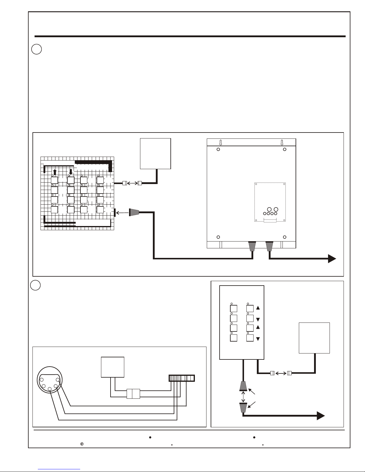
D - Installation Instructions ( See Figs. 4 & 5 below).
1. Install the OPTIMA in a convenient location. Fig. 4 shows an OPTIMA-DS which has a female XLR connector
mounted on the side of its aluminium enclosure. OPTIMA-DS2 models are mounted in deep single gang masonry
boxes and have a female XLR connector mounted externally (See Fig. 5 below).
2. Provide a standard power outlet with a toggle switch for the wall transformer. Plug the supplied transformer to the
OPTIMA using the Molex connector plugs. The OPTIMA may remain energized at all times. The loads can be turned
off by using the front panel ‘Black-Out’ button.
3. Install the DMX dimmer pack and follow the wiring instructions in its user manual.
4. Connect the OPTIMA to the Dimmer Pack using the DMX cable (DMX-CC-LEN) to either internally or externally
mounted XLR connector. Skip to Operating Instructions.
9V Wall
DMX 3 - 8 Channel Controllers
OPTIMA-DS
Lighting Animation Controller
Adapter
PD408-DMX
MODE
RUN
RATE
MAX.
LEVEL
MIN.
LEVEL
FADE
AUTO
STOP
BLK.
OUT
Digital Lighting Systems
digitallighting.com
Miami, Fl. USA
DIM1
DIM2
DIM3
DIM4
Molex Plugs
DMX-CC-LEN
Fig. 4 OPTIMA-DS Installation Drawing
E - OPTIMA DMX and Power Connections
The OPTIMA panels use a standard 5-Pin Female XLR connector to
connect to DMX equipment as seen in Figs. 4 & 5. They are also
available on request with an unterminated pigtail that plugs into the
back of the unit so that customer may make their own DMX connections
or with a pre-terminated cable with XLR connector to the customer’s
desired length (J8FXLR5-L). An external transformer supplies power via
a 2-pos. Molex type connector.
Power and DMX pin assignments are shown in Fig. 6.
TO DMX
Equipment
5
1
4
2
3
5-Pin Female
XLR Connector
Ground Shield
-D
+D
J8FXLR5-L - L = Length in feet.
Fig. 6 - DMX Output Pin Assignments.
9V Wall
Adapter
Molex Connector
AC1
AC2
To Port (7)
On Back Of Panel
3 4
5 6 7 8
1 2
1
4
6
2
3
ADDRESS SELECTORS
LED OUTPUT
MONITORS
OPTIMA-DS2
4 channel logic DMX512
Fade/
Chase
Auto/
Man.
ALL
ON
ALL
OFF
J8FXLR5-L
DMX-CC-LEN
INT04
S1S2
3
4
1 2
Fig. 5 OPTIMA-DS2
Installation Drawing
Pattern
Speed
Molex Plugs
XLR Connectors
To more DMX
Dimmer Packs
9V Wall
Adapter
To DMX
Dimmer Packs
7588 NW 8th Street, Miami, Fl. 33126
Tel: 305-264-8391 Fax: 305-261-6637or 1-877-264-8391
Specifications are subject to change without notice.Copyright 1999 Digital Lighting Systems, All rights Reserved
Printed in U.S.A.
OSUM
Rev. A 09/01
Page 6
Digital Lighting Systems
OPTIMA-DS Operating Instructions
OPTIMA-DS
DMX 3 - 8 Channel Controllers
User's Manual - Page 5
I. Introduction
The OPTIMA-DS is a 16-pattern, DMX-512 chaser/cross-fader logic
controller. The number of channels can be set to any value from 3 to 8 using
a rotary slector on the back of the unit. Maximum and minimum level
adjustment masters are provided with individual control for the first 4
channels. When operating as a chaser, The OPTIMA-DS switches its
outputs between maximum and minimum levels. When cross-fading, the
outputs gradually ramp from one level to the next.
The OPTIMA-DS has simple to use push-button controls with LED
indicators. Following is a description of the buttons and the various functions
they perform.
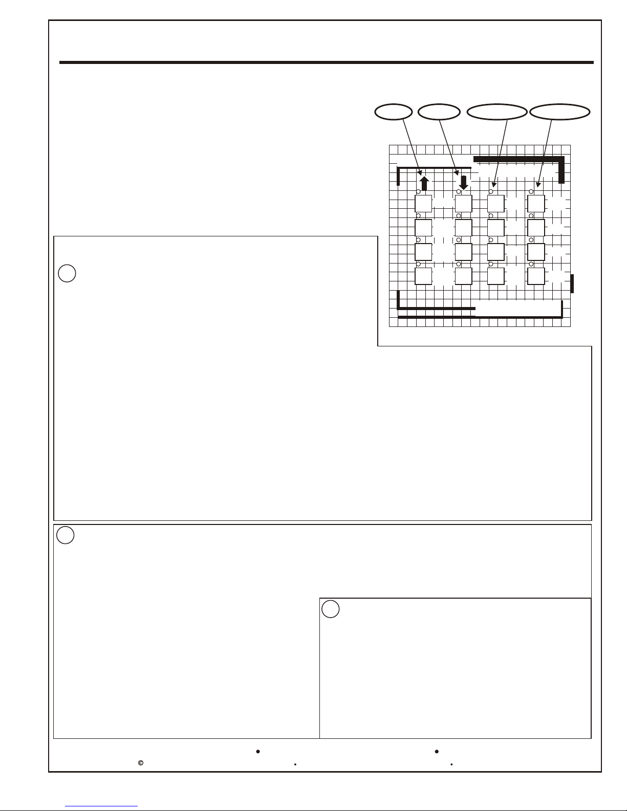
II. The Control Panel
A - Dual Button Controls
The following four pairs of up/down control buttons are used to select the
chase (or fade) pattern, the chase (or fade) rate and to set the minimum
and maximum master levels. Momentarily pressing and releasing a button
causes the associated value to increment (decrement) in single steps.
Pressing and holding a button causes a more rapid variation that stops
when the button is released.
1- MODE (Up-Down Buttons)
The “MODE” up-button increments the pattern number from 1
to 16. Its associated LED turns on when pattern number 16 is
reached. The “MODE” down-button performs the reverse
operation and its associated LED turns on when pattern
number 1 is reached.
2- RUN RATE (Up-Down Buttons)
The “RUN RATE” up-button increments the chase speed from 1 to
255. Its associated LED turns on when the speed reaches a
maximum of 255. The “RUN RATE” down-button performs the
reverse operation and its associated LED turns on when the
speed reaches a minimum of 1.
UP DOWN DIMMERS
TOGGLES
OPTIMA-DS
Lighting Animation Controller
MODE
RUN
RATE
MAX.
LEVEL
MIN.
LEVEL
Fig. 7 The OPTIMA DS Front Panel
FADE
AUTO
STOP
BLK.
OUT
Digital Lighting Systems
Miami, Fl. USA
digitallighting.com
DIM1
DIM2
DIM3
DIM4
3- MAX. LEVEL (Up-Down Buttons)
The “MAX. LEVEL” up-button is used to gradually increase
the maximum master level up to 100%. Its associated LED
turns on when 100% is reached. The “MAX. LEVEL” downbutton performs the reverse operation and its associted LED
turns on when 0% is reached.
4- MIN. LEVEL (Up-Down Buttons)
The “MIN. LEVEL” up-button is used to gradually increase the
minimum master level up to 100%. Its associated LED turns on
when 100% is reached. The “MIN. LEVEL” down-button performs
the reverse operation and its associted LED turns on when 0% is
reached. The minimum level is used to prevent the outputs from
completely turning off. This feature creates a very attractive
special effect to lighting displays.
B - Single Button Toggle Controls
The following four buttons work as toggles. They turn the function on, if previously off, and turn it off, if previously on.
1 - FADE SELECT
If the fade mode had been previously selected, depressing the Fade
Select button switches the OPTIMA DS to the chase mode and viceversa. The associated LED turns on when the selected mode is fade.
2 - AUTO SELECT
Selecting the AUTO mode causes the OPTIMA-DS to automatically
scroll through all 16 chase patterns. Otherwise, the same pattern
repeats unless changed using the MODE up/down buttons. The
associated LED is on when Auto is selected.
3 - STOP SELECT
Selecting the STOP mode stops the chasing and fading cycles and
causes all channels to go into a static mode. The OPTIMA-DS
effectively becomes a simple DMX console with 4 individually
dimmable channels, using DIM1 to DIM4 buttons, and a MAX. LEVEL
master. The LED associated with the STOP button turns on to indicate
that the OPTIMA-DS is operating in a static dimmer mode.
4 - BLKOUT SELECT
When selected, the associated LED turns on. All channels are blacked
out and go to 0% intensity.
C - DIMMER buttons
DIM1-DIM4
The individual levels of the outputs can be adjusted to any level
between 0% and 100%, using the DIM buttons in conjunction
with the maximum master control. Each DIM button performs
Raise and Lower functions alternately. Pushing and holding a
button causes the level of the corresponding output to vary in
one direction. Releasing the button and pressing again causes
the output level to vary in the reverse direction.
The LED’s above the DIM buttons indicate the output status of
the first four channels.
7588 NW 8th Street, Miami, Fl. 33126
Tel: 305-264-8391 Fax: 305-261-6637or 1-877-264-8391
Specifications are subject to change without notice.Copyright 1999 Digital Lighting Systems, All rights Reserved
Printed in U.S.A.
OSUM
Rev. A 09/01
Page 7
Digital Lighting Systems
OPTIMA-DS
OPTIMA-DS2/DS2-C Operating Instructions
III. Introduction
The OPTIMA-DS2 and DS2-C are
simplified versions of the OPTIMA-DS
controller. They have the same features
as the DS with the exception on the
master and individual dimming controls.
The DS2-C is the same as the Ds2 but is
locked on “chase only” by setting selector
S2 to 0. The FADE button on the DS2-C is
deactivated and does not perform any
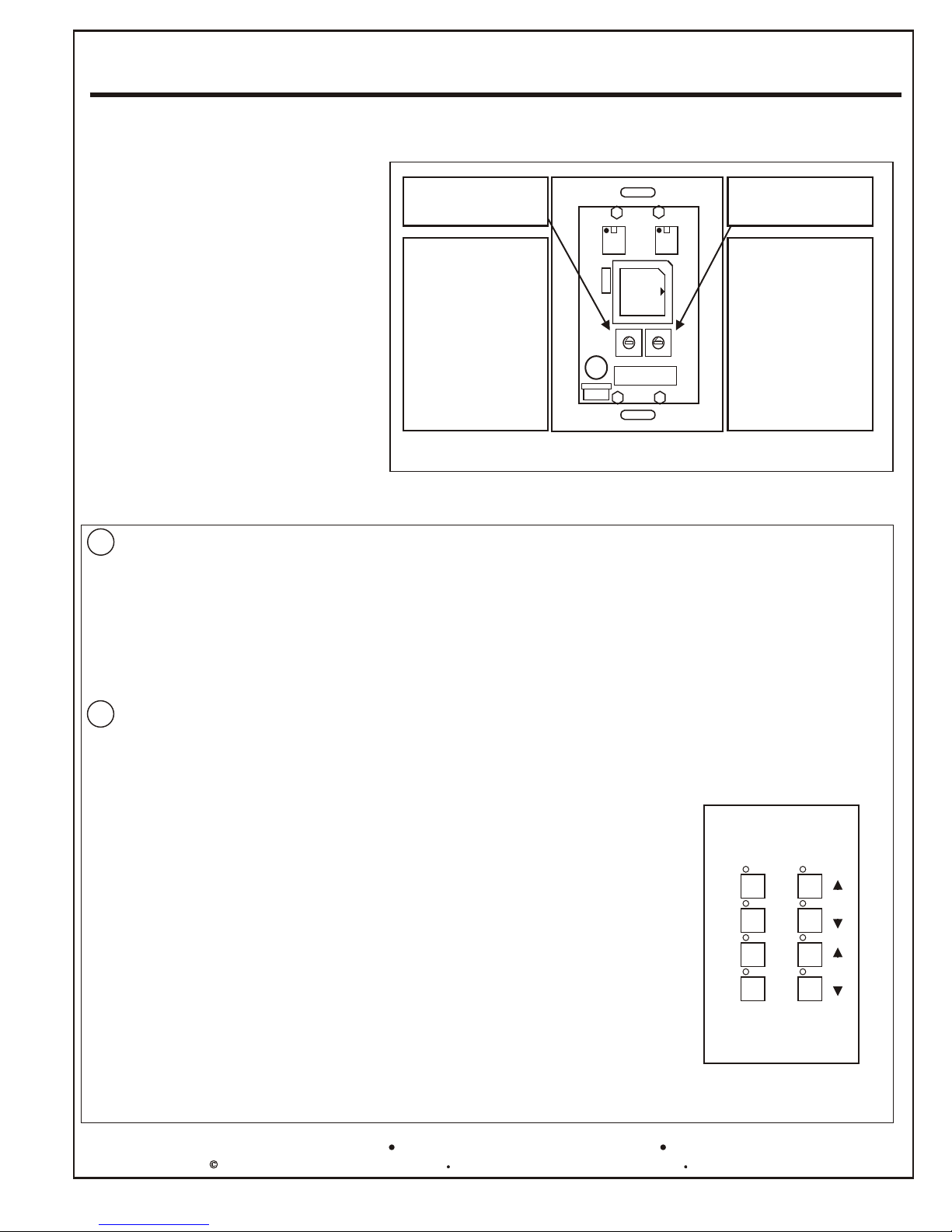
IV. Number of Channels
Configuration
The number of channels on both models
can be set to any value between 3 to 8
usaing rotary selector S1 on the back of
the unit. Refer to Fig. 8 to the right.
DMX 3 - 8 Channel Controllers
User's Manual - Page 6
Selector S2
Chase/Fade
OPTIMA-DS2 set to
“F”
(Chase and Fade)
OPTIMA-DS2-C set
to “0”
(Locked on Chase
Only)
S2
2
2
1
1
3
3
0
0
4
4
F
F
5
5
E
E
6
6
D
D
7
7
C
B
S1
C
8
8
9
9
B
A
A
Selector S1
Number of Channels
Using a small tip
screw driver, rotate
the shaft and
position the arrow at
the desired number.
Valid range: from 3
to 8 Channels.
Fig. 8 OPTIMA - number of Channels and Chase/Fade Selection
V. The Control Panel - See figure 9 below.
A - Dual Button Controls
1- PATTERN (Up-Down Buttons)
The “PATTERN” up-button increments the pattern number from 1 to 16. The “PATTERN” down-button performs the reverse
operation until number 1 is reached.
2- SPEED (Up-Down Buttons)
The “SPEED” up-button increments the chase speed from 1 to 255. The “SPEED” down-button performs the reverse operation
until it reaches a minimum of 1.
The LED’S above these buttons indicate the output status of the first four channels.
B - Single Button Toggle Controls
The following four buttons work as toggles. They turn the function on, if previously off, and turn it off, if previously on.
1 - FADE/CHASE SELECT
If the fade mode had been previously selected, depressing the Fade Select button
switches the OPTIMA-DS2 to the chase mode and vice-versa. The associated LED
turns on when the selected mode is fade. (Feature disabled on DS2-C version.)
2 - AUTO/MAN. SELECT
Selecting the AUTO/MAN. mode causes the OPTIMA-DS2 to automatically scroll
through all 16 chase patterns. Otherwise, the same pattern repeats unless changed
using the PATTERN up/down buttons. The associated LED is on when Auto is
selected.
3 - ALL ON SELECT
Selecting the ALL ON mode stops the chasing and fading cycles and causes all
channels to go into a static ALL ON mode. The associated LED is on when ALL ON
is selected.
OPTIMA-DS2
4 channel logic DMX512
Fade/
Chase
Auto/
Man.
ALL
ON
ALL
OFF
Pattern
Speed
4 - ALL OFF Select
All channels are blacked out and go to 0% intensity. When selected, the associated
LED turns on.
7588 NW 8th Street, Miami, Fl. 33126
Fig. 9 The OPTIMA-DS2 Front Panel
Tel: 305-264-8391 Fax: 305-261-6637or 1-877-264-8391
Specifications are subject to change without notice.Copyright 1999 Digital Lighting Systems, All rights Reserved
OSUM
Rev. A 09/01
Printed in U.S.A.
Page 8
Digital Lighting Systems
DMX 3 - 8 Channel Controllers
OPTIMA-DS
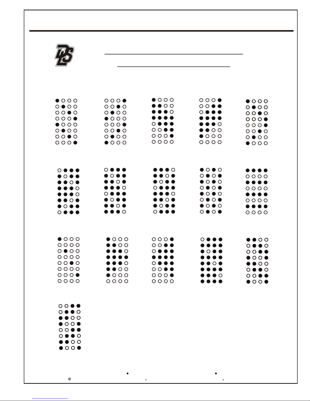
Patterns for OPTIMA Series
Chasers/Cross-Faders
User's Manual - Page 7
1
Light Chase
6
Dark Bounce
11
Flash Light Chase
2
Light Chase Back
7
Dark Chase
12
Spring Forward
3
Fill & Swipe Forward
8
Dark Chase Back
13
Spring Back
4
Fill & Swipe Back
9
Flip-Flop
14
Flash Dark Chase
5
Light Bounce
10
Flash All
15
Crawl Forward
16
Crawl Back
7588 NW 8th Street, Miami, Fl. 33126
“All On”/ “All Off” and “Auto Cycle
through patterns 1-16” are available
by pressing STOP/ BLK OUT and
AUTO buttons respectively.
Tel: 305-264-8391 Fax: 305-261-6637or 1-877-264-8391
Specifications are subject to change without notice.Copyright 1999 Digital Lighting Systems, All rights Reserved
Printed in U.S.A.
OSUM
Rev. A 09/01
Page 9

LIMITED WARRANTY
Digital Lighting Systems, warrants to the purchaser that its
products have been carefully manufactured and inspected and
are warranted to be free from defects of workmanship and
materials when used as intended. Any abuse or misuse contrary
to normal operation shall void this warranty.
Digital Lighting Systems' obligation under this warranty shall be
limited to replacement or repair of any units as shall within one
year of date of invoice from Digital Lighting Systems, prove
defective; and Digital Lighting Systems shall not be liable for
any other damages, whether direct or consequential. The
implied warranties of merchantability and fitness for a
particular purpose are limited to the duration of the
expressed warranty. Some states do not allow the exclusion of
the limitation of incidental or consequential damages, so the
above limitation or exclusion may not apply to you. This
warranty gives you specific legal rights, you may also have other
legal rights which vary from state to state.
Defective merchandise may be returned to Digital Lighting
Systems, prepaid, after prior notification has been given and
approval obtained for the return. To obtain prior approval for the
return of the defective items, contact your local Digital Lighting
Systems distributor, representative, or:
Digital Lighting Systems, Inc.
Attn: Customer Service Department
7588 NW 8th Street
Miami, FL 33126
(305) 264-8391
Upon request, replacement unit(s) will be shipped as soon as
available. Unless immediate shipment of replacement
merchandise is requested, Digital Lighting Systems will not
ship replacement merchandise until defective merchandise is
received, inspected, and determined to be defective.
No labor charges in connection with warranty problems will
be reimbursed by Digital Lighting Systems without prior
written approval from the factory.
Digital Lighting Systems distributors and representatives have
no authority to change this warranty without written permission.
Digital Lighting Systems reserves the right to determine the
best method of correcting warranty problems.
Page 10

Digital Lighting Systems, Inc.
7588 NW 8th Street
Miami, FL 33126
www.digitallighting.com
Printed in U.S.A.
August 2001
 Loading...