

Digitalk 2 - WAY COMMUNICATOR Owner's Manual And Operating Instructions
OWNER'S MANUAL AND
OPERATING INSTRUCTIONS
2 - WAY COMMUNICATOR
PLEASE READ THIS
OWNER MANUAL
CAREFULLY BEFORE USE.
KEEP FOR YOUR
REFERENCE.
FOR INSTALLATION INSTRUCTIONS PLEASE SEE PAGE 6.
DW
M
Special Features
PRODUCT DESCRIPTION
The COMMUNICATOR is the newest generation in personal two-way
communications. The COMMUNICATOR operates in a radio band , on
any of the 40 channels. (Refer to "channel table" section on page 19 for
more information.)
The COMMUNICAT OR is a lightw eight, compact tw o-w ay comm unication
device that can be used to communicate with family or friends at parks,
shopping malls, sporting ev ents, concerts -- any indoor or outdoor activity!
The COMMUNICATOR is compatible with other brands utilizing the same
frequency band (operating in the frequency range from 476.425MHz to
477.400MHz).
BUSY
SCAN
VOX
C
The COMMUNICAT OR has 40-CHANNELS, featuring a multi-functional LCD
Screen (which displays the current channel and various status icons).
Other features include ELECTRONIC VOLUME CONTROL, BATTERY SAVE
CIRCUITRY and DUPLEX MODE.
Please read this Owner's Manual carefully to get the most out of your
TWO-WAY COMMUNICATOR.
NOTE: The maximum transmission range will vary depending on terrain
and environment. Range will be greater in open fields, while range
is shorter within and around buildings or large structures.
This unit may not ensure privacy of communication.
1
Contents
Preparation
Communicator Controls - Location & Function
Getting Started
Removing Belt Clip
Installing Belt Clip
Battery Installation
LCD Screen
Turning the Unit ON
Turning the Unit OFF
Adjusting Speaker Volume
Receiving a Signal
Transmitting a Signal
Operation
Changing Channels
..........................................................................................................
Monitor
Enter / Back-Light / Button Lock
Channel Scan
Sending Call Tones
Battery Level Indicator
.......................................................................................
.........................................................................................
.......................................................................................
...................................................................................................
......................................................................................
......................................................................................
..........................................................................
.......................................................................................
....................................................................................
....................................................................................
................................................................
..............................................................................................
.......................................................................................
................................................................................
2 3
.......................................
Contents
4
6
6
7
8
9
9
9
9
9
10
10
10
11
11
12
Battery Charge Indication
To Charge the Communicator
Dual Watch
Internal VOX Control Function
Second Counter Function
Duplex Function
Other Information
Troubleshooting
Care and Maintenance
Specifications
..................................................................................................
..........................................................................................
............................................................................................
...............................................................................................
..........................................................................
...................................................................
...................................................................
.........................................................................
..............................................................................
12
12
13
13
14
14
15
16
19
Communicator Controls
17
16
15
14
13
12
11
10
BUSY
DW
SCAN
VOX
C
M
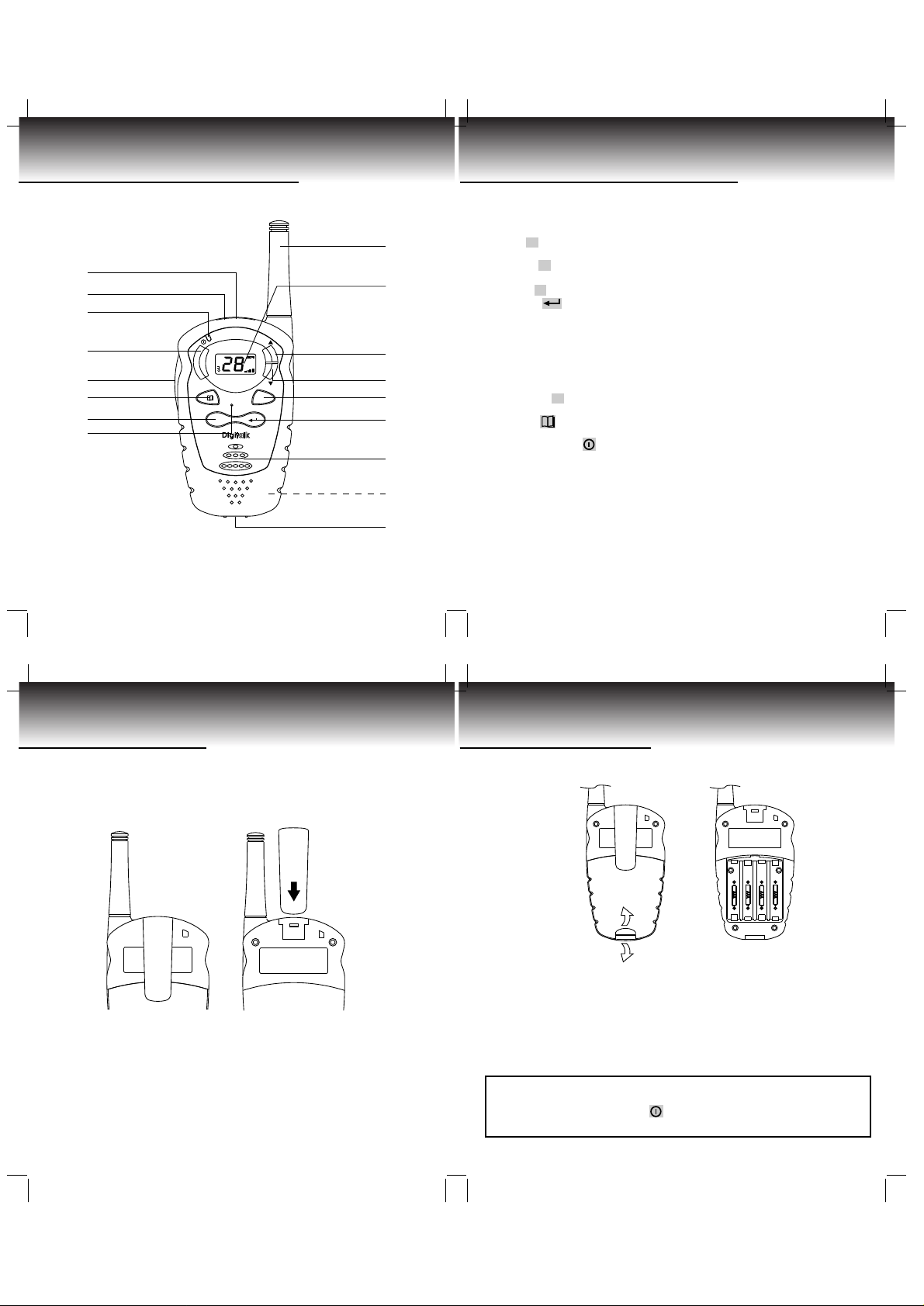
Communicator Controls
1. Antenna (Pg. 16, 18)
2. LCD Screen: Displays current channel selection and other radio status
symbols. (Pgs. 8-10, 12, 13)
1
2
3
4
5
6
7
8
9
3. Up ▲ button (VOLUME/CHANNEL): Press to adjust volume level and
change channels. (Pgs. 9-11, 13-15)
4. Down ▼ button (VOLUME/CHANNEL): Press to adjust v olume le v el and
change channels. (Pgs. 9-11, 13-15)
5. Call C button: Press to transmit CALL TONES. (Pg. 11,13)
6. Enter
are locked when pressed and held. (Pg. 10, 11,13,14)
7. Speaker (Pg. 9)
8. Battery Compartment (LOCATED ON THE REAR): Houses 4 x "AAA"
alkaline or Ni-MH rechargeable batteries (not included). (Pgs. 7, 15)
9. Battery Compartment Cover Latch (LOCATED ON THE REAR): Secures
Battery Compartment cover. (Pg. 7)
10. Mic: Microphone. (Pgs. 9, 15)
11. Monitor M button: Press to tune in and hold onto weak signals. (Pgs.
9-11,13,15)
12. Menu button: Allows you to change channels. (Pgs. 10,11, 13-15)
13. PUSH TO TALK PTT button: Press to transmit. (Pgs. 9,11, 13,14)
14. Power On/Off button: Press and hold the button to turn your unit
ON/OFF. (Pgs. 7, 9)
15. TX (Transmission) LED indicator: Illuminates red when transmitting. (Pgs.
9, 11, 12, 14)
16. SP. Jack: When earphone is connected into this jack, voice of the
speaker will shift to earphone.
17. Belt Clip (LOCATED ON THE REAR) (Pg. 6)
18. Mic. Jack / Battery Charge Jack (Pg. 12)
button: Used to turn LCD Screen LAMP ON/OFF Buttons
4
Getting Started
Carefully remove your communicator from its packing. If there is any
visible damage, do not attempt to operate this communicator. Return
it to the place of purchase
Removing the BELT CLIP:
Figure 1. Figure 2.
1. Pull the BELT CLIP LATCH away from the unit.
2. While pulling the BELT CLIP LATCH, push up on the BELT CLIP to remove
it from the unit. See Figure 1.
Installing the Belt Clip:
1. Slide the BELT CLIP into the BELT CLIP SLOT. See Figure 2.
2. A "click" indicates the BELT CLIP is locked into position.
5
Getting Started
Battery Installation:
Figure 3. Figure 4.
1. Release the BATTERY COMPARTMENT COVER LATCH located on the
rear side of the unit (see Figure 3) and remove the BATTERY
COMPARTMENT COVER from the BATTERY COMPARTMENT (See Figure
4).
2. Install 4x1.5V AAA alkaline batteries or Ni-MH rechargeable batteries
(not included) as shown.
3. Reinstall the BATTERY COMPARTMENT COVER and lock the BATTERY
COMPARTMENT COVER LATCH into position.
The COMMUNICATOR has a built in POWER SAVER feature for maximum
battery life. But when the COMMUNICATOR is not being used, conserve
battery power by pressing the button to OFF. Remove the batteries if
the unit will not be used for a long period of time.
6
7
 Loading...