

Page 1
EDU-KIT-001 Installation Guide
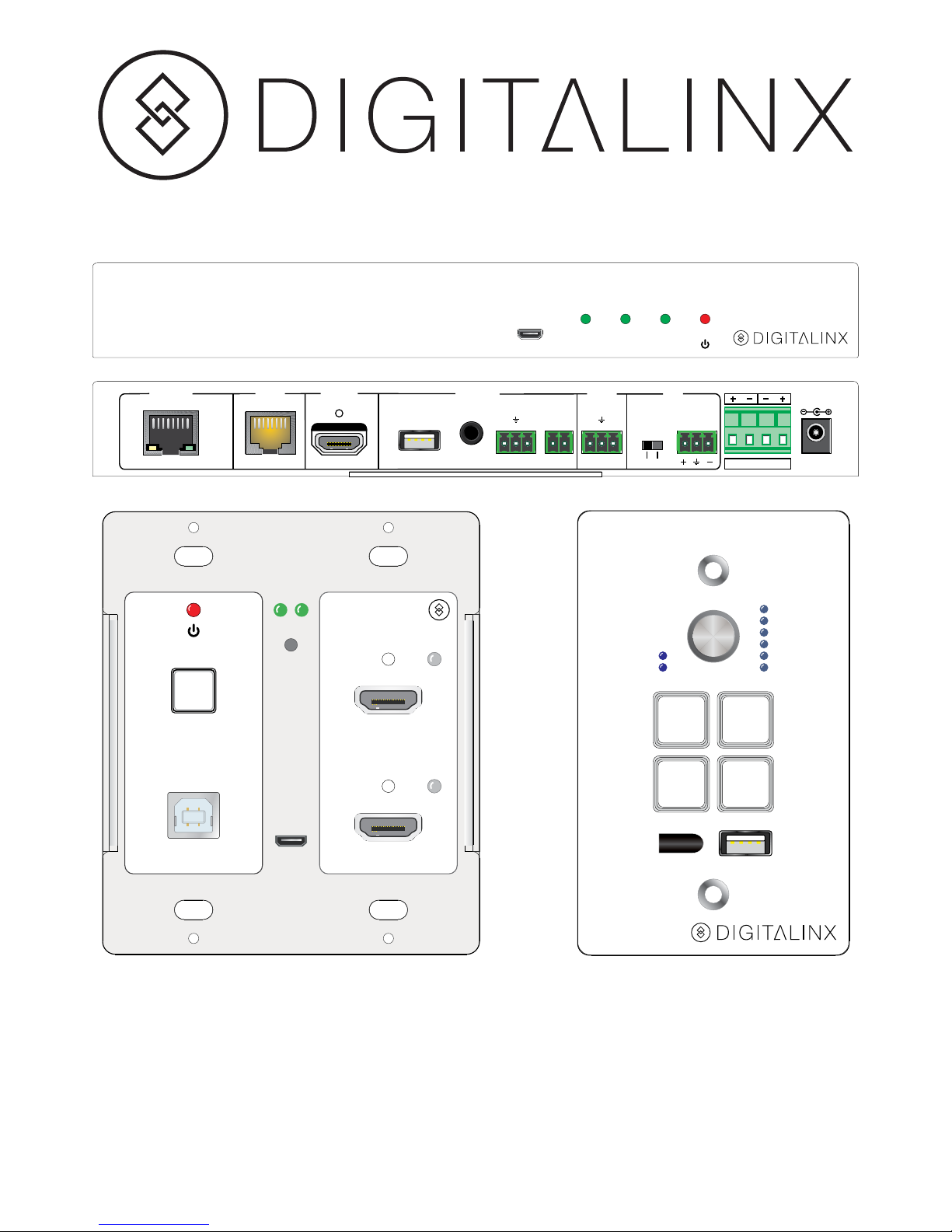
The Digitalinx EDU-KIT-001 is a multi-function AV distribution system designed to
provide HDMI video switching, system control, video extension and analog audio
amplification in a convenient kit. Utilizing the Valens Colligo VS2110 series chips, power,
control, video up to 1080p, and audio are transported over a single 30m (98 ft) Category
6A cable between the wall plate transmitter and the receiver. The wall plate control
module connects to the wall plate transmitter with a second Category 6A cable. All
the power needed for the system is provided by the receiver. Additionally, the receiver
features a built-in web GUI for control and analog audio de-embedding to a built-in
2x20 watt stereo amplifier.
FIRMWARE
ON LINK HDCP
EDU-KIT-001
RX / Receiver
OUTPUT CONTROL AUDIO MICINPUTNETWORK
2x20 Watts @ 4Ω
24V DC
LINE
MIC
MIC
RL
LINE OUT
TX RX
RS232IR OUT
REMOTE
MUTE
FROM
TOUCHSCREEN
TO DISPLAYHDBT IN/PoC
TCP/IP
HDMI IN 1SOURCE SELECT
TO PC HDMI IN 2
FIRMWARE
RESET
HDCPLINK
VOLUME
MIC
SOURCE
ON
HDMI 1IRHDMI 2
CONFIG
OFF
Page 2

Page 3

Included Accessories
Safety Precautions
• Receiver
• Transmitter
• Control Panel
• Locking Power Supply with Power Cable
• USB Type A to Type B Cable
• 3-pole to DE9 RS232 Cable
• IR Emitter
• Two Mounting Rails with Screws
• Six Wall Box Screws
• Three 3-pole Removable Terminal Blocks
• One 2-pole Removable Terminal Block
• One 4-pole Removable Terminal Block
• Installation Guide
To insure the best from the product, please read all instructions carefully before using
the device. Save this manual for further reference.
• Unpack the equipment carefully and save the original box and packing material for
possible future shipment.
• Follow basic safety precautions to reduce the risk of fire, electrical shock and injury
to persons.
• Do not dismantle the housing or modify the module. It may result in electrical shock
or burn.
• Using supplies or parts not meeting the products’ specifications may cause damage,
deterioration or malfunction.
• Refer all servicing to qualified service personnel.
• To prevent fire or shock hazard, do not expose the unit to rain, moisture or install
this product near water.
• Do not put any heavy items on the extension cable in case of extrusion.
• Do not remove the housing of the device as opening or removing housing may
expose you to dangerous voltage or other hazards.
• Install the device in a place with good ventilation to avoid damage caused by
overheating.
• Keep the module away from liquids.
• Spillage into the housing may result in fire, electrical shock, or equipment damage. If
an object or liquid falls or spills on to the housing, unplug the module immediately.
• Do not use liquid or aerosol cleaners to clean this unit. Always unplug the power to
the device before cleaning.
• Unplug the power cord when left unused for a long period of time.
• Information on disposal for scrapped devices: do not burn or mix with general
household waste. Please treat them as normal electrical waste and recycle the
devices properly.
Page 4
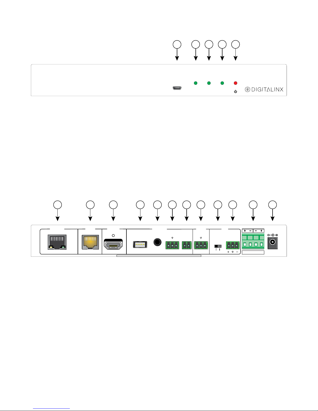
Receiver Front Panel
Receiver Rear Panel
FIRMWARE
ON LINK HDCP
EDU-KIT-001
RX / Receiver
1
2 3 4 5
OUTPUT CONTROL AUDIO MICINPUTNETWORK
2x20 Watts @ 4Ω
24V DC
LINE
MIC
MIC
RL
LINE OUT
TX RX
RS232IR OUT
REMOTE
MUTE
FROM
TOUCHSCREEN
TO DISPLAYHDBT IN/PoC
TCP/IP
A B C D E F G H I J K L
1. Firmware Update Port
2. System Power Indicator
3. HDBaseT Link Indicator
4. HDCP Status Indicator
5. Receiver Power Indicator
A. Network Port
B. HDBaseT Input and PoC Output
C. HDMI Output
D. USB Port to Touchscreen Display
E. IR Output to Display
F. RS232 Output to Display
G. Remote Mute Contact Closure
H. Line Level Analog Audio Output
I. Line/Mic Level Selector Switch
J. Microphone Input
K. Speaker Output
L. 24V DC Power Input
Page 5
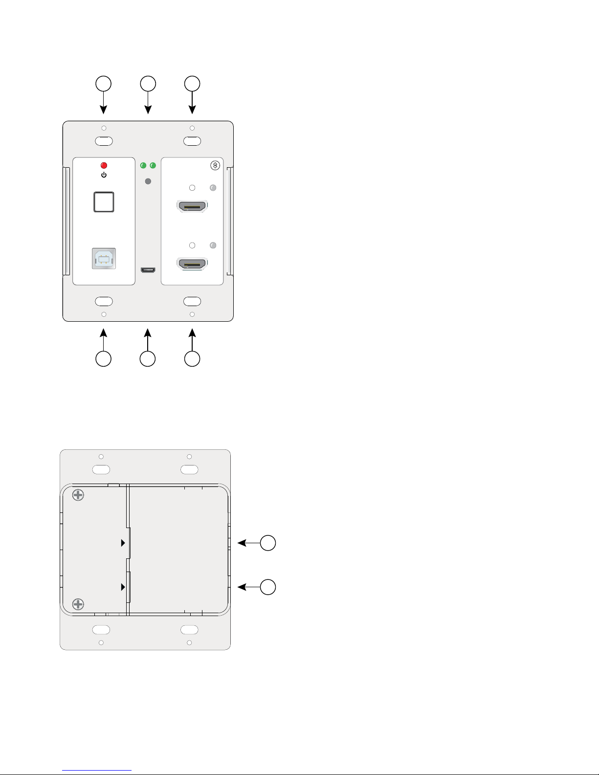
Transmitter Front
Transmitter Rear
HDMI IN 1SOURCE SELECT
TO PC HDMI IN 2
FIRMWARE
RESET
HDCPLINK
1 2 3
4 5 6
A
B
PoC IN
HDBT OUT
POWER
RS232
EDU-KIT-001
TX / Transmitter
1. Power Indicator and Source Select Button
2. Link and HDCP Status LEDs and Reset Button
3. HDMI Input 1 with Activity Indicator
4. USB Port to Host PC
5. Firmware Update Port
6. HDMI Input 2 with Activity Indicator
A. HDBaseT Output and PoC Input
B. Power and RS232 to Control Panel
Page 6
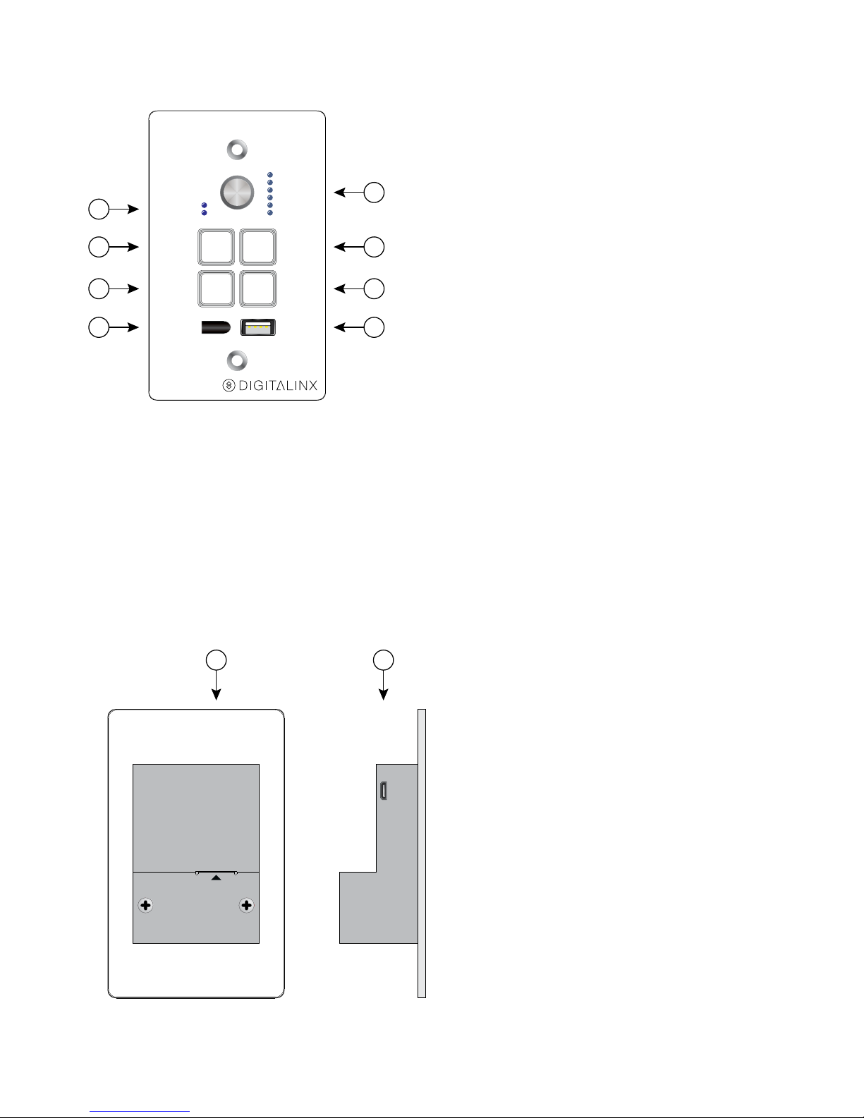
Control Panel Front
Control Panel Rear
VOLUME
MIC
SOURCE
ON
HDMI 1IRHDMI 2
CONFIG
OFF
1
5
2
3
4
6
7
8
POWER
RS232
FIRMWARE
EDU-KIT-001
PAD / Control Pad
A B
1. Mic/Source Indicator
2. System/Display On Button
3. HDMI Input 1 Select Button
4. IR Receiver
5. Multifunction Volume Control with
Volume Level Indicator
6. System/Display Off Button
7. HDMI Input 2 Select Button
8. Configuration Port
A. Power and RS232 from Transmitter
B. Firmware Update Port
Page 7
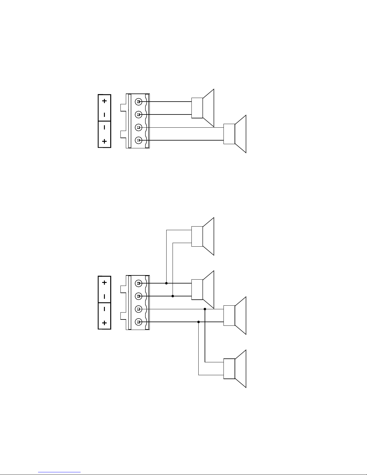
Speaker Wiring Configurations
4Ω Load with 4Ω Speakers
+
–
4Ω
+
–
4Ω
4Ω Load with 8Ω Speakers
+
–
+
–
8Ω
8Ω
+
–
+
–
8Ω
8Ω
Page 8

1. Verify all components included with the EDU-KIT-001 are present before
installation.
2. Turn off power and disconnect the audio/video equipment by following the
manufacturer’s instructions.
3. Attach the included rubber feet or mounting ears to the receiver.
4. Connect an HDMI cable between the HDMI output of the Receiver and the HDMI
input of the display. The HDMI cable should not exceed 5 meters (16 feet).
5. Connect a microphone to the microphone input connector.
a. “+” connects to positive
b. “–’ connects to negative
c. “╧” connects to ground.
6. Adjust the microphone input mode selector based on the type of microphone to
be connected to the Receiver.
a. MIC – 48dB gain
b. LINE – 4dB gain
7. Connect the speakers to be used in accordance with the Speaker Wiring
Configurations. If an external audio amplifier is to be used with the system, connect
the unbalanced analog audio output of the Receiver to the input of the amplifier.
8. If the display is to be controlled via IR, plug the IR emitter to the IR Out port of
the Receiver and mount the IR emitter bud to the IR receiver port of the display.
9. If the display is to be controlled via RS232, plug the 3-pole terminal plug end of
the included RS232 cable into the RS232 port on the Receiver and the DE9 end to
the display.
10. Connect a USB cable between the display’s interactive white board USB port and
the USB port labeled “From Touchscreen” on the rear of the Receiver.
11. Connect a Category 6A or greater cable between the Network TCP/IP port and the
facility’s network.
12. Connect a Category 6A or greater cable between the Input port of the Receiver and
the Output port of the Transmitter. This cable cannot exceed 30 meters (98 feet).
13. Connect a Category 6A or greater cable between the Power and RS232 port on the
Transmitter and the Power and RS232 port on the Control Panel.
14. Connect the included USB cable between the TO PC port on the front of the
Transmitter and the PC to receive the commands from the interactive white board.
15. Plug the power supply into the power input port on the Receiver.
16. Power on the Receiver by plugging the power cable into the power supply.
17. Power on all audio/video devices.
Installation Instructions
Page 9

IR Learning
Enter IR Learning Mode
Exit IR Learning Mode
Programming the Display On and Display Off Functions
If the power command for the display remote is a toggle, use the same button for the
ON and OFF commands below.
Press and hold the HDMI 1 button on the Control Panel for three seconds. The ON and
OFF buttons will light up.
Press and hold the HDMI 2 button on the Control Panel for three seconds. The ON and
OFF buttons will go dark.
1. Press the ON button, and it will start to flash.
2. Point the display remote at the Control Panel IR sensor and the press the Power
On button on the remote. The ON button on the Control Panel will stop flashing.
3. Press the OFF button, and it will start to flash.
4. Point the display remote at the Control Panel IR sensor and the press the Power
Off button on the remote. The OFF button on the Control Panel will stop flashing.
Page 10
Web Browser Configuration
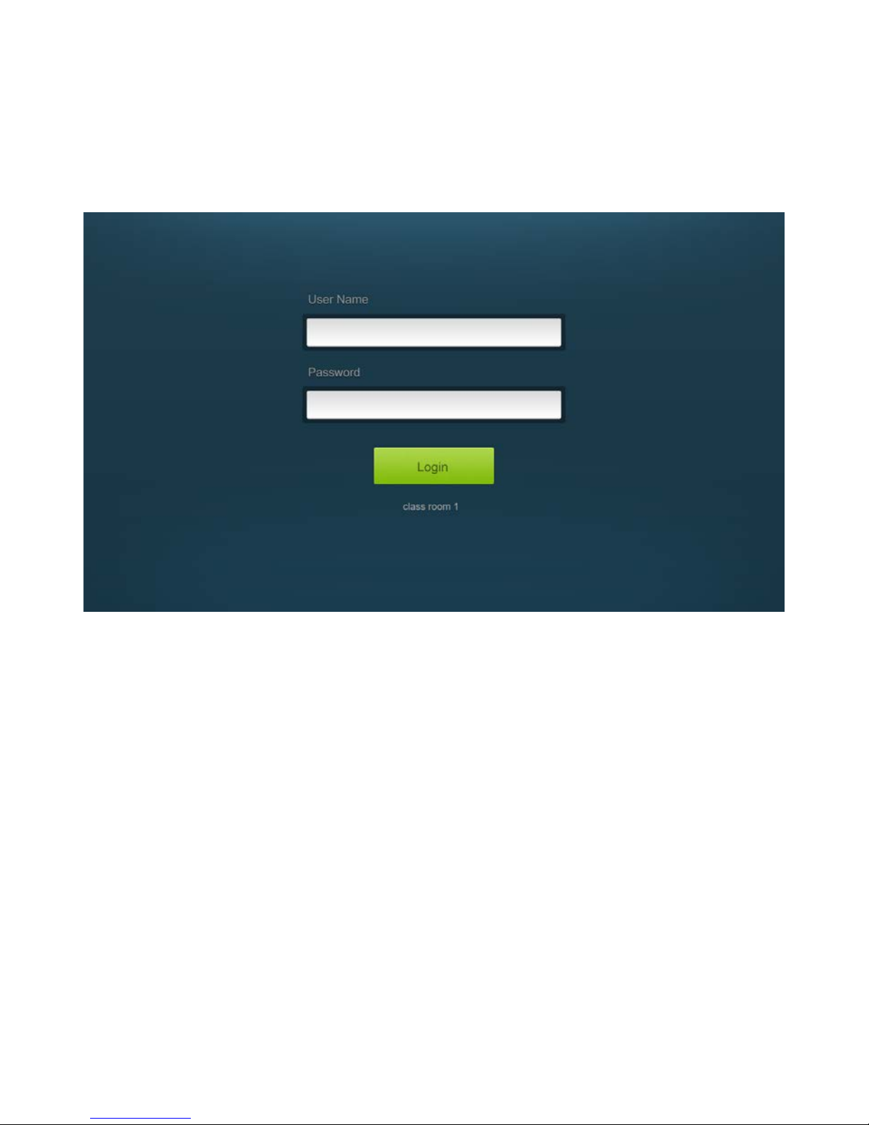
Logging In
The default IP address of the EDU-KIT-001 is 192.168.0.178. This can be changed in the
Network settings.
To change the settings of the web browser interface or program RS232 commands for
the display, log into the EDU-KIT-001 as an administrator. The User Name is admin and
the default Password is admin.
Page 11
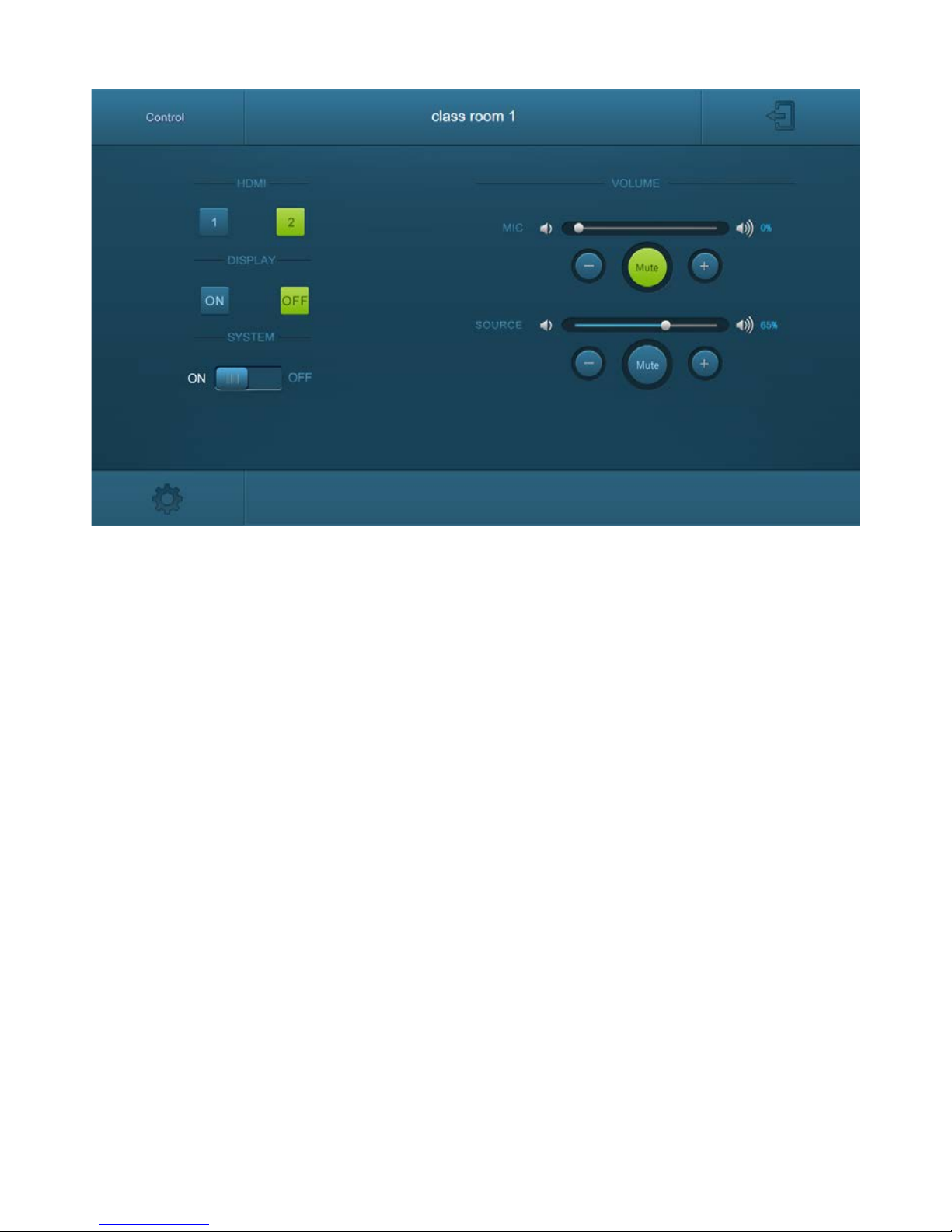
Device Control Screen
HDMI
Switch between HDMI 1 and HDMI 2.
Display
Turn the display on or off.
System
Turn the system on or off.
Volume
Mute and unmute audio sources. Volume may be changed by pressing the “+” or “-“
buttons or by dragging the volume slider.
To enter the configuration settings, click on the gear icon on the lower left corner of
the Control interface.
Page 12
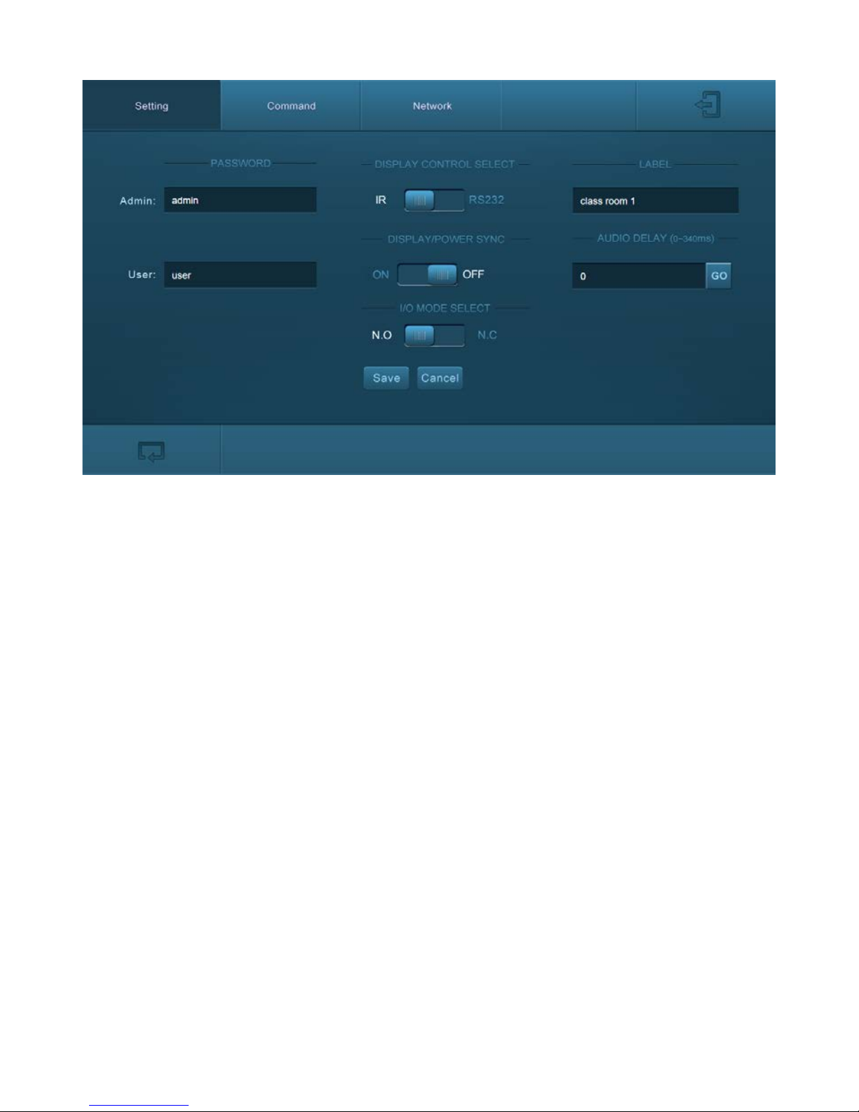
Setting Tab
Password
Change the password for the admin and user login screen.
Display Control Select
Select whether the display will be controlled via IR or RS232.
Display/Power Sync
Select whether the display and system will be powered on and off simultaneously. This
option is only active if the display is controlled via RS232.
I/O Mode Select
Select whether the contact closures need to be normally open (N.O.) or normally closed
(N.C.) to mute the audio output for integration with a mass notification system.
Label
Rename the label at the top of the Control screen.
Audio Delay
Sets up the audio delay to sync the audio with the video on the display. The delay time
is 0 to 340 ms. Click the GO button the activate the new value.
Save/Cancel
Saves or cancels changes made to this screen.
Page 13
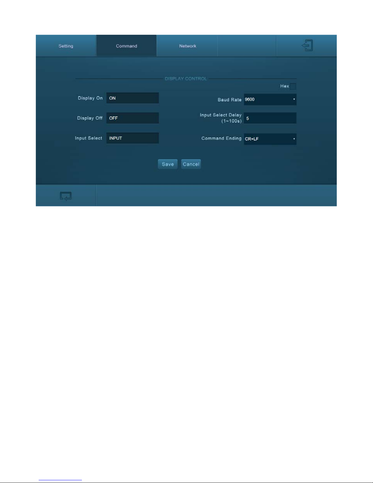
Command Tab (RS232 Display Control)
This tab defines the RS232 display control commands. If a display requires hex
commands, make sure the Hex box is checked.
Display On
Enter the RS232 command to turn on the display.
Display Off
Enter the RS232 command to turn off the display.
Input Select
Enter the RS232 command to switch to the input which is connected to the Receiver.
Baud Rate
Select the baud rate necessary to communicate with the display. Available baud rates
are: 2400, 4800, 9600, 14400, 19200, 38400, 56000, 57600, and 115200 baud.
Input Select Delay
Enter the delay time in seconds between the Power On and Input Select commands.
This delay may be between 1 and 100 seconds.
Command Ending
Select the command ending after each RS232 command. Available command endings
are: null, carriage return, line feed, and carriage return and line feed.
Save/Cancel
Saves or cancels changes made to this screen.
Page 14
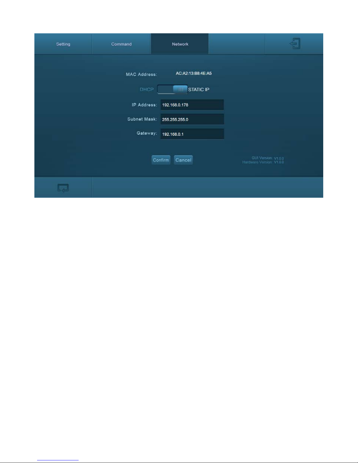
Network Tab
DHCP/Static IP
Select whether the system will use a static IP or will be provided an IP via DHCP.
IP Address
Enter the IP address for the system.
Subnet Mask
Enter the subnet mask for the system.
Gateway
Enter the gateway address for the system.
Save/Cancel
Saves or cancels changes made to this screen.
Page 15

Transmitter Operation
Control Panel Operation
Power On and Off the System
Power On and Off the Display
Select Input Sources
Volume Control Functions
Plugging in an HDMI source will automatically switch to that input. Pressing the
Source Select button will switch sources.
To power on the system, press and hold the ON button on the Control Panel for
three seconds. If the display is controlled via RS232, the display and system power on
functions may be tied together.
To power off the system, press and hold the OFF button on the Control Panel for
three seconds. If the display is controlled via RS232, the display and system power off
functions may be tied together.
To power on the display, press the ON button on the Control Panel.
To power off the display, press the OFF button on the Control Panel.
Press the HDMI 1 or HDMI 2 buttons on the Control Panel to select the appropriate
source device.
Turning the Volume knob clockwise will raise the volume; counterclockwise will lower
the volume.
Pressing the Volume knob will mute or unmute the current audio source.
Pressing and holding the Volume knob for three seconds will switch to the other audio
source. If the audio source is muted, this action will unmute the source.
Page 16
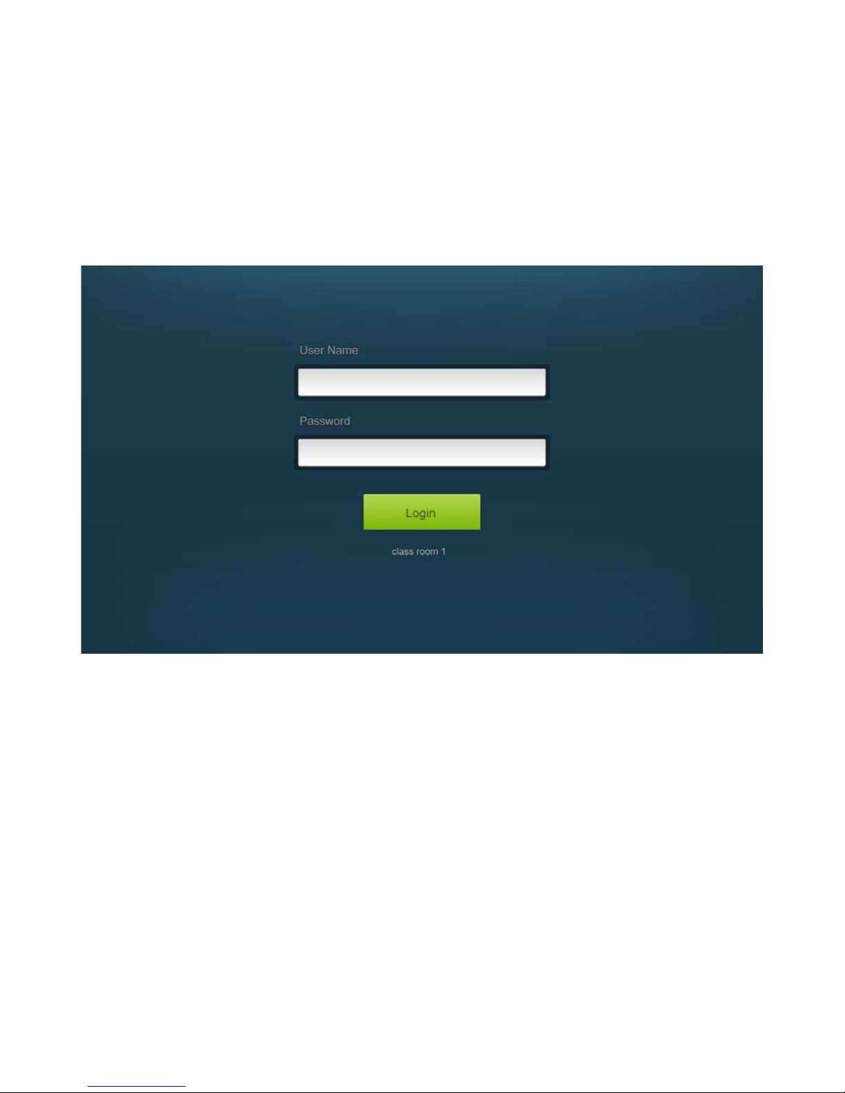
Web Browser Control
Logging In
The web browser control interface is an alternative method to control the system
without having to interact with the Control Panel.
The default IP address of the EDU-KIT-001 is 192.168.0.178. This can be changed in the
Network settings by an administrator.
The User Name is user and the default Password is user.
Page 17
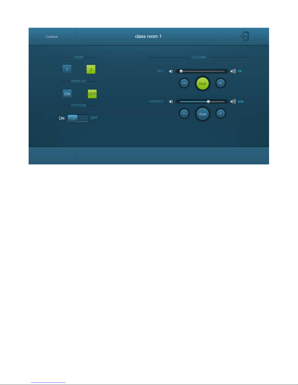
Device Control Screen
HDMI
Switch between HDMI 1 and HDMI 2.
Display
Turn the display on or off.
System
Turn the system on or off.
Volume
Mute and unmute audio sources. Volume may be changed by pressing the “+” or “-“
buttons or by dragging the volume slider.
Page 18

Copy and Load Control Settings
Copy Control Settings
Load Control Settings
The system IR or RS232 configuration can be copied to a USB thumb drive and loaded
into additional systems or be saved as a backup.
Insert a 4GB or smaller FAT32 formatted thumb drive into the Configuration port on
the front of the Control Panel.
Simultaneously press and hold the OFF and HDMI 2 buttons on the Control Panel for
three seconds. As soon as the buttons are released, they will light up while the copy is
in progress.
Remove the thumb drive from the Configuration port once the buttons go dark.
Insert a 4GB or smaller FAT32 formatted thumb drive with saved configuration settings
into the Configuration port on the front of the Control Panel.
Simultaneously press and hold the ON and HDMI 1 buttons on the Control Panel for
three seconds. As soon as the buttons are released, they will light up while the upload
is in progress.
Remove the thumb drive from the Configuration port once the buttons go dark.
Page 19
Firmware Update
Web GUI
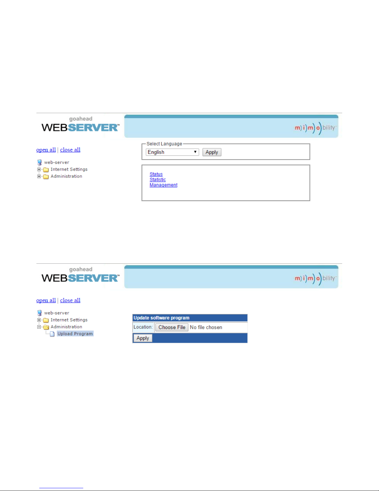
Open a web browser and enter the IP address of the Receiver directed at port 100. If
the IP address is at 192.168.0.178, enter 192.168.0.178:100 into the web browser.
When prompted, enter the admin username and password (admin and admin by
default). Once logged in, the following screen will be available.
Click the plus symbol next to Administration, then click on Upload Program to upload
the new firmware.
Click the Choose File button and navigate to the web GUI update file. The web GUI
update file will have Ralink in the file name. After the file is selected, click on Apply.
A confirmation dialog window will open to verify the new software will be uploaded to
the device. The web page will appear to load for about 30 seconds while the web GUI
software is being uploaded into the receiver. Once complete, the receiver will reboot.
Page 20
Receiver Update
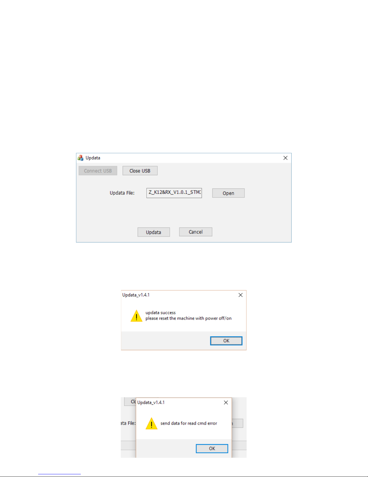
Copy the upgrade software (updata.exe) and the firmware file (.bin with RX in the file
name) to a folder on the computer’s desktop.
Connect a micro USB type B cable between the computer and the Firmware port on
the Receiver.
Run the upgrade software.
Click the Connect USB button.
Click Open, then navigate to the location of the firmware file for the Receiver.
Click Updata to start the firmware upgrade.
When the firmware is uploaded successfully, a popup window will open stating to
reboot the device.
Close the Updata software.
If the firmware update fails, close the upgrade software and power cycle the device.
Running the software from a USB drive has been known to cause issues with updating
the firmware. Occasionally, a USB to RS232 adapter may cause conflicts with the
firmware update.
Page 21

Transmitter Update
Control Panel Update
The firmware update procedures for the Transmitter are identical for the receiver. The
firmware file for the Transmitter will have TX in the file name.
The firmware update procedures for the Control Panel are identical for the receiver. The
firmware file for the Control Panel will have WP4 in the file name.
Page 22

FCC Statement
This equipment generates, uses and can radiate radio frequency energy and, if not
installed and used in accordance with the instructions, may cause harmful interference
to radio communications. It has been tested and found to comply with the limits for a
Class B digital device, pursuant to part 15 of the FCC Rules. These limits are designed to
provide reasonable protection against harmful interference in a commercial installation.
Operation of this equipment in a residential area is likely to cause interference, in
which case the user at their own expense will be required to take whatever measures
may be necessary to correct the interference.
Any changes or modifications not expressly approved by the manufacture would void
the user’s authority to operate the equipment.
Page 23

Technical Specifications
Supported Audio, Video and Control
Maximum Video Compatibility Deep Color 48/36/30/24 Bit at 1080p
Video Compliance HDMI 1.4, HDCP 1.4
HDMI EDID Pass-through from Display
Embedded Audio Up to PCM 2 channel
Analog Audio Frequency Response 20Hz-20KHz
Analog Audio Output Impedance 50 Ω Analog Output; 4/8 Ω Speaker Output
Maximum Rated Power Output (Audio) 40 Watts
Maximum Passive HDMI Distance 5 m (16 ft)
IR Carrier Frequency Range 33-55kHz at 5 volts
RS232 Baud Rate 2400, 4800, 9600, 14400, 19200, 38400, 56000, 57600, and
115200 baud
Ethernet 100BaseT
USB Supports USB 2.0
Contact Closure NO and NC for system mute
HDBaseT Signal Characteristics
Maximum Distance 30 m (98 ft)
Cable Requirements Solid core Category 6A or greater with TIA/EIA-568B crimp
pattern
Bandwidth 10.2 Gbps
HDBaseT Chipset VS2110 series chipsets
Other
Standard Warranty 2 Years
Included Items Receiver, Transmitter, Control Panel, Locking Power Supply with
Power Cable, USB Type A to Type B Cable, 3-pole to DE9 RS232
Cable, IR Emitter, Two Mounting Rails with Screws, Six Wall Box
Screws, Three 3-pole Removable Terminal Blocks, One 2-pole
Removable Terminal Block, One 4-pole Removable Terminal
Block, Installation Guide
Distances and picture quality may be affected by cable grade, cable quality, source and
destination equipment, RF and electrical interference, and cable patches.
Page 24

rev 160307
11675 Ridgeline Dr.
Colorado Springs, CO 80921
Toll-Free: 800-530-8998
Fax: 719-260-0075
www.libav.com
Digitalinx is a brand of Liberty AV Solutions.
 Loading...