

Page 1
User’s Manual
Fiber Optic Extender
Part #: DL-HDFO
Page 2

1-1
1-1 Table of Contents
1-2 Welcome and Safety Notes
1-3 FCC Statement of Compliance
1-4 Product Description and General Specications
1-5 Environmental Reliability Specications
1-6 Installation Procedures
1-8 Mechanical Specications
1-9 Technical Specications
1-10 Warranty Information
1-11 Troubleshooting and Customer Service information
TABLE OF CONTENTS
Table of Contents
Page 3

1-2
Congratulations on your purchase of a Digitalinx™ Fiber Optic Extender.
This manual contains information that will assist you in the installation and
operation of this product. Please inspect the contents of the package to
ensure all required material is present.
Contents:
Each Digitalinx™ Fiber Optic Extender package contains the
following items:
1 each DL-HDFO Fiber Optic Extender set.
(1) Transmitter and (1) receiver make up the set.
1 eachDC Power Supply (UL) and C(UL) listed Class 2 C(UL)US
2 each 1 Meter HDMI Interconnect Cables
1 each Users Manual
***NOTE***
User responsible items are the multimode Fiber Optic cable(s) and an equal length RJ45 Category 5E
patch cord. Liberty Wire and Cable P/N DL-1N4F is a riser rated combination 4 ber and Category 5E
cable under on jacket to support installs of this product.
Safety Precautions:
1.) Please read all product manuals and safety notes prior to operating
this or any devices.
2.) Retain the product manuals and safety notes for future reference
3.) Unplug this unit prior to cleaning; do not use liquid cleaners or aerosol
cleaners. Use a damp cloth for cleaning.
4.) Do not use this equipment near damp or wet locations.
5.) The product should only be powered by the indicated sources in the
specications. Do not use other sources of power.
6.) Do not use damaged power cords or plugs and do not use loose
electrical outlets. Please refer repair of non-conforming electrical
equipment to certied personnel.
7.) Do not place heavy articles or other equipment on top of this device
or its associated peripherals.
8.) Do not use this device near ammable material, liquids, or gas.
9.) Do NOT unplug the LC connectors and look directly into the connector
or receptacle when operating. This device is regulated as Laser Class 1
and severe eye damage can result.
Welcome and Safety Notes
Welcome and Safety Notes
Page 4

1-3
This device complies with part 15 of FCC Rules. Operation is subject to the
following two conditions: (1) this device may not cause harmful interference,
and (2) this device must accept any interference received, including
interference that may cause undesired operation. This equipment has
been tested and found to comply with the limits for a Class B digital device
pursuant to part 15 and 2 of FCC Rules, EN 55022/55024/61000-3 for CE
certication. These limits are designed to provide reasonable protection
against harmful interference when the equipment is operated in a residential
installation. This equipment generates, uses, and can radiate radio frequency
energy. If the device is not installed and used in accordance with the
instruction guide it may cause harmful interference to radio communications.
However, there is no guarantee that interference will not occur in a particular
installation. If this equipment does cause harmful interference to radio or
television reception, which can be determined by turning the equipment on
and o, the user is encouraged t try to correct the interference by one or more
of the following:
• Re-orient or relocate the receiving antenna.
• Increase the separation between the equipment and the receiver.
• Connect the equipment into an outlet on a circuit dierent from that
to which the receiver is connected.
• Consult a service representative for help.
Properly shielded and grounded cables and connectors must be used in
order to comply with FCC/CE emission limits. Changes or modications not
expressly approved by the party responsible for compliance could void the
user’s authority to operate the equipment.
Certication for Safety
The extension system is certied pursuant to IEC60065 and its AC/DC power
adapter is certied by UL310, 1950, 60950 for North America, c(UL) or CSA for
Canada, TUV-CE & GS for the EU and PSE for Japan.
Certication for Eye Safety
This laser product is implemented by using 850nm VCSEL (Vertical Cavity
Surface Emitting Laser) Transceivers manufactured by RTCom Co. Ltd which is
certied by CDRH/FDA referred in Accession Number 0210774 as classied in
Laser Class 1.
FCC/CE Statement for regulations of Electro-magnetic emissions
Welcome and Safety Notes
Page 5
1-4
This Digitalinx™ Fiber Optic Extender is an externally powered digital HDMI
and DVI extender system. The unit uses a supplied 12 VDC power source.
Only one unit, either the Transmitter or the Receiver, requires the power
supply. The device is compliant with DVI 1.0 and HDMI 1.2a signals. The
device is fully compliant with HDCP protocol. This device is classied as
Standard Speed for HDMI 1.3 applications.
This Digitalinx™ Fiber Optic Extender is ideal for long distance HDMI and
DVI applications where a small form factor cable is required. The unit will
extend the signal to 100 meters (328 feet) and oers maximum bandwidth
and awless transmission of digital multimedia. The unit uses 4 Fiber Optic
Multimode LC channels to transmit R, G, B, and Clock with a copper Category
5/5e cable for DDC and power distribution. This device can also be used to
achieve plenum cabling possibilities for HDMI and DVI via the use of plenum
rated Fiber Cable and Plenum rated Category 5/5e cable.
The system can easily accommodate DVI only inputs and outputs by using
Liberty’s high quality HDMI to DVI interconnects. The DVI connector is routed
to the sources and display unit while the HDMI connector plugs into the
Digitalinx™ Fiber Optic Extender. The digital audio signal is not transmitted
when using DVI connectors.
Product Description and General Specications
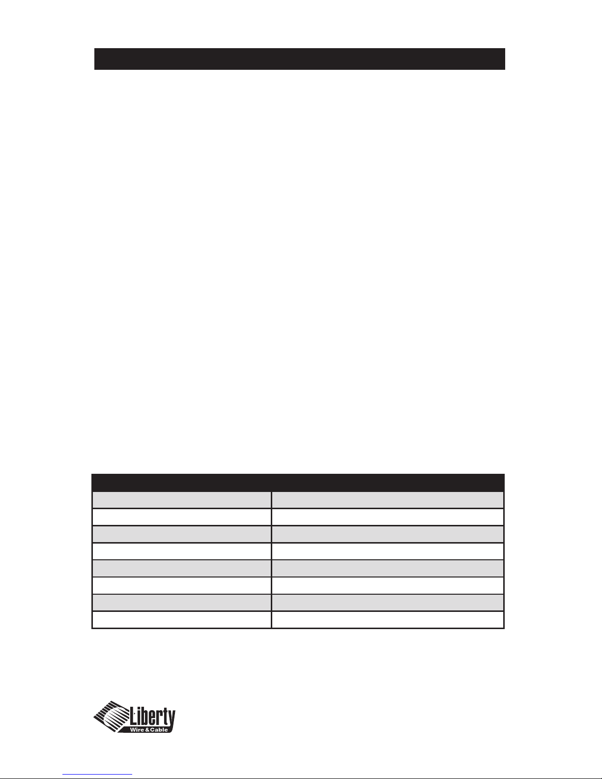
ITEM DESCRIPTION
Model Name DL-HDFO
Input HDMI type A Receptacle
Output HDMI type A Receptacle
Maximum Resolution UXGA (1600x1200)@75Hz, HDTV 1080p60
HDCP Compatible Yes
Power Consumption 12VDC, 3.0A
Dimensions: (Height x Width x Depth) TX/RX 19x38x72mm
Weight ~0.46 Kg each unit
Product Description and General Specications
Page 6

1-5
The Digitalinx™ Fiber Optic Extender recommended environmental operating
limits are a temperature range from 10°C to 40°C, non-condensing humidity
levels from 10-80% and an altitude ceiling of 3,000 meters (9,840 feet).
Environmental limits for transportation are established as a temperature
range of -25°C to 60°C, non-condensing humidity levels from 5-95%, and an
altitude ceiling of 15,000 meters (49,200 feet)
Environmental limits for storage are established as a temperature range of
-20°C to 45°C, non-condensing humidity levels from 5-95%, and an altitude
ceiling of 3,000 meters (9,840 feet)
The Digitalinx™ Fiber Optic Extender is expected to function for more than
50,000 hours of use at a 90% condence level. The device is tested to the
identical standards used for testing LCD monitors.
Environmental Reliability Specications
Environmental Reliability Specications
Page 7
1-6
Important: Please ensure the installation procedure below is followed.
Improper operation or no operation of the devices may result if these are
not followed. Installation assumes Fiber Cable(s) and Category 5/5e cable is
previously installed and has been conrmed good.
1.) Carefully unpack the contents of the shipping package and verify all
components are present.
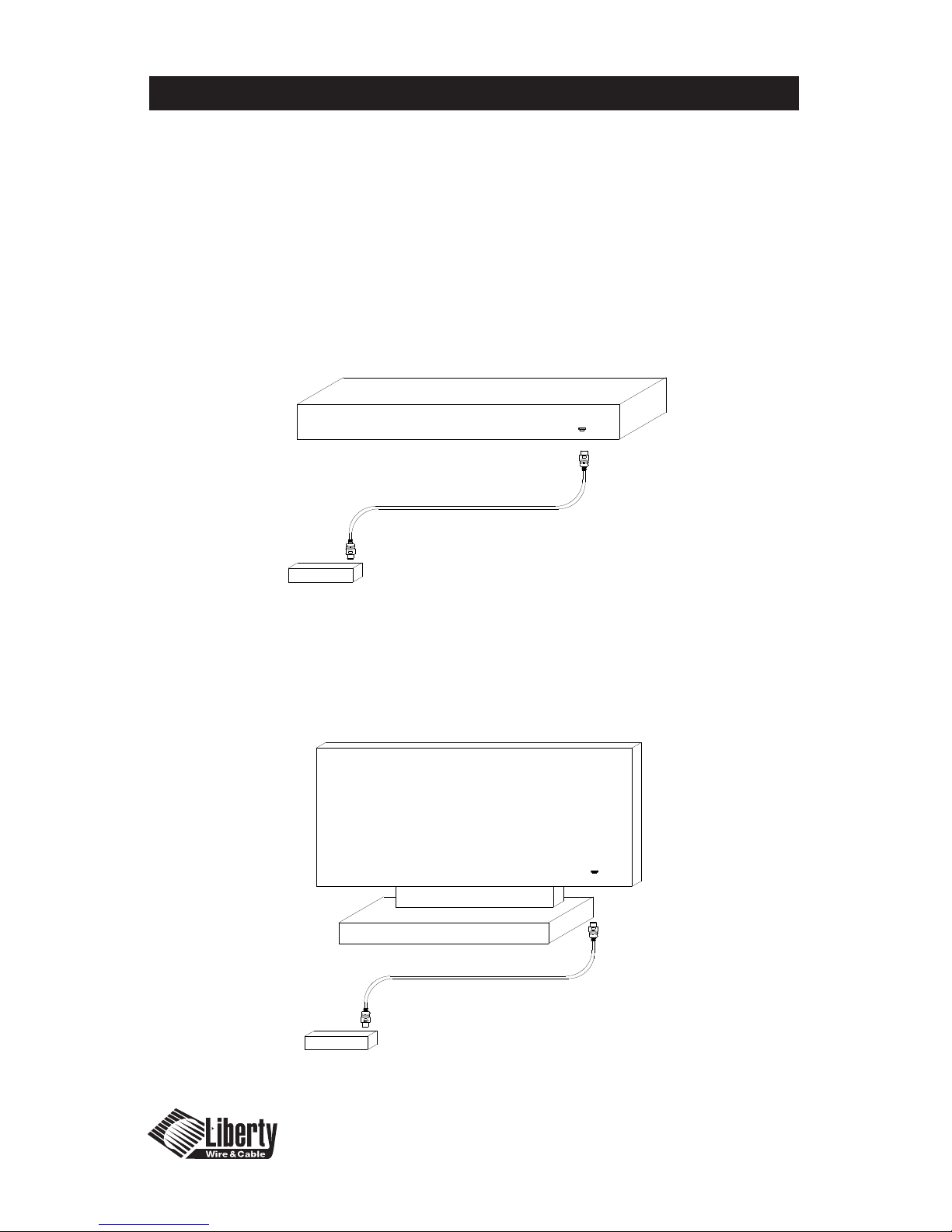
2.) With all components powered down (HDMI source and Display) connect the
TX box to the HDMI source using a copper HDMI interconnect cable from 1-8
meters in length.
3.) With all components powered down (HDMI source and Display) connect the
RX box to the HDMI Display using a copper HDMI interconnect cable from 1-8
meters in length.
Installation
Installation
DL-HDFO TX Unit
HDMI or DVI Source Unit
LWC
LWC
Installation Procedures
Important: Please ensure the installation procedure below is followed. Improper operation or no
operation of the devices may result if these are not followed. Installation assumes Fiber Cable(s) and
Category 5/5e cable is previously installed and has been confirmed good.
1.) Carefully unpack the contents of the shipping package and verify all components are present.
2.) With all components powered down (HDMI source and Display) connect the TX box to the HDMI
source using a copper HDMI interconnect cable from 1-8 meters in length.
DL-HDFO TX Unit
HDMI or DVI Source Unit
LWC
LWC
DL-HDFO RX Unit
LWC
LWC
Display Unit
Installation Procedures
Important: Please ensure the installation procedure below is followed. Improper operation or no
operation of the devices may result if these are not followed. Installation assumes Fiber Cable(s) and
Category 5/5e cable is previously installed and has been confirmed good.
1.) Carefully unpack the contents of the shipping package and verify all components are present.
2.) With all components powered down (HDMI source and Display) connect the TX box to the HDMI
source using a copper HDMI interconnect cable from 1-8 meters in length.
3.) With all components powered down (HDMI source and Display) connect the RX box to the
HDMI Display using a copper HDMI interconnect cable from 1-8 meters in length.
Page 1-6
Page 8
1-7
Installation Continued
Features
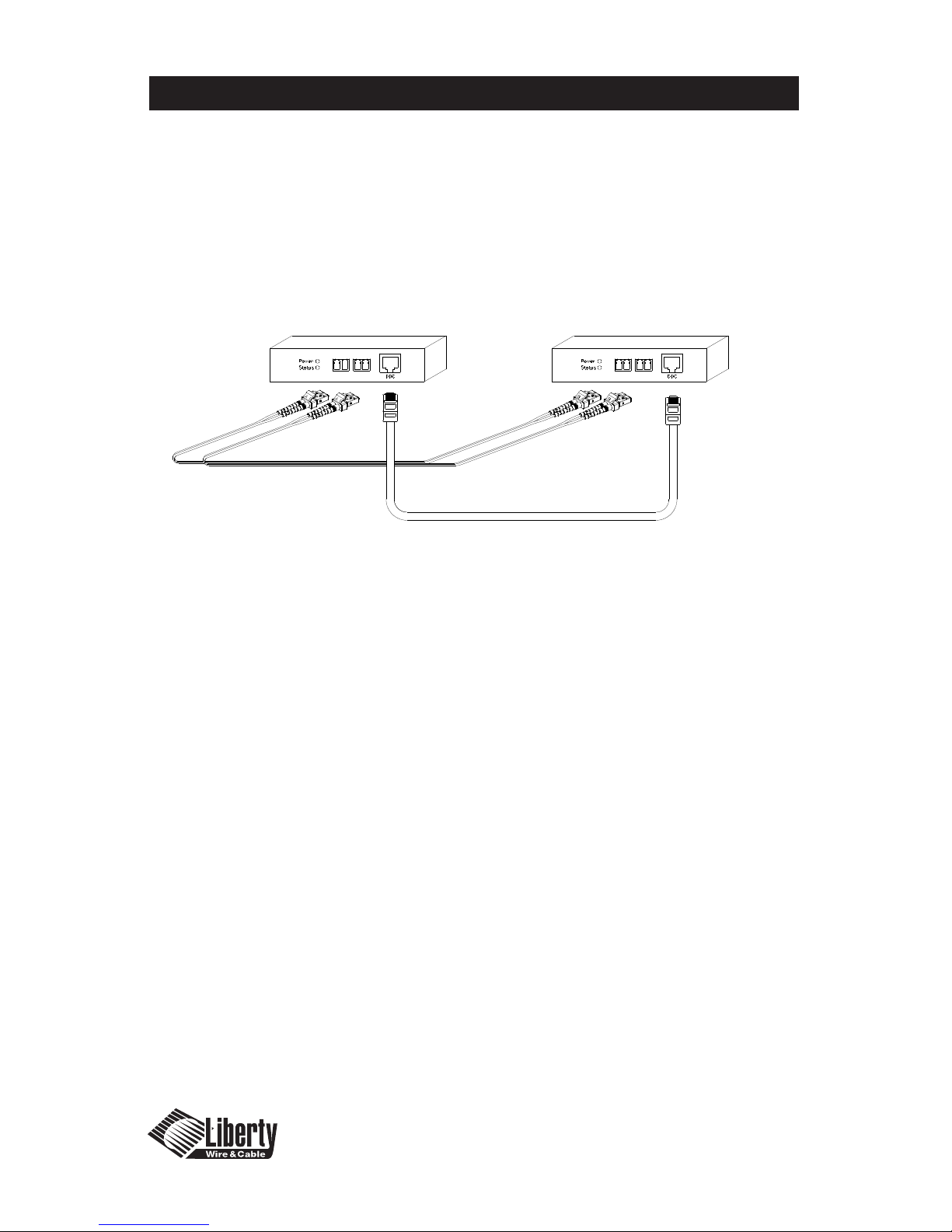
4.) Remove the dust covers from the Fiber Optic LC receptacles and connect each
Duplex LC cable one by one to each of the four LC receptacles. Plug A to A and
B to B. Carefully recheck polarities and ensure the duplex connectors are fully
engaged and locked in place.
5.) Connect the RJ45 plug to each RJ45C receptacle of the TX
and RX boxes.
6.) Connect the DC power supply to either the TX or the RX unit depending on
your availability of and AC power source. This will power up both of the units.
The power receptacle is located on the same side as the HDMI receptacle.
Ensure both units have power by viewing the power LED. SAFETY NOTE:
Do NOT unplug the LC connectors and look directly into the connector or
receptacle when operating. This device is regulated as Laser Class 1 and severe
eye damage can result.
7.) Power up the Display side (Display can reference Media Receiver, Computer
Monitor or Display).
8.) Power up the Source side.
9.) The Status LED on both the TX and RX units should be illuminated Green. If it
is not illuminated check the Polarity on the LC connectors. Failure of the LED to
illuminate can be caused by a poor ber connection, broken ber, or incorrect
polarity on the LC plugs.
a.) Tip – After initial power up shut down all displays and sources and repeat the
start up operation
b.) Do not “Hot Plug” the TX and RX units. Ensure sources and displays are
powered down prior to hookup.
10.) Note: It is recommended to use the longest run of cable between the source
and the Fiber Optic Extender followed by a shorter run when possible to reap
the greatest benet of the signal boost.
11.) The length of the HDMI or DVI cable on the source side should be 8 meters
or less due to source signal inconsistencies. The length from the RX unit to the
display should be one size less then the source side. For example an 8 meter
cable on the source would have a 7 meter or shorter cable on the display side.
4321 3412
DL-HDFO TX Unit
DL-HDFO RX Unit
Installation Procedures Continued
4.) Remove the dust covers from the Fiber Optic LC receptacles and connect each Duplex LC cable
one by one to each of the four LC receptacles. Plug A to A and B to B. Carefully recheck
polarities and ensure the duplex connectors are fully engaged and locked in place.
5.) Connect the RJ45 plug to each RJ45C receptacle of the TX and RX boxes.
Page 9
1-8
Mechanical Specications
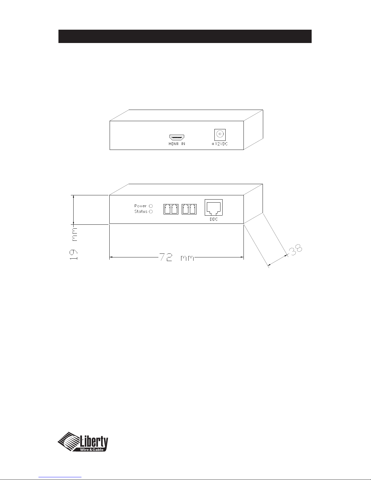
Dimensions:
DL-HDFO TX and RX Units: HxWxD 19mm x 38mm x 72mm
HDMI IN: HDMI from digital media source TX only
HDMI OUT: HDMI to digital video display RX only
LED Power: 12 VDC power Indicator.
LED Status: Fiber Optic status indicator, green.
1-4: LC Receptacles for R, G, B, and Clock
DDC: RJ45 Receptacle, Power, DDC, CEC and HDCP
Mechanical Specications
4
321
Mechanical Specifications
Page 10
1-9
Technical Specications
Frequency Bandwidth: 1.65 Gbps
Supporting Graphic Resolution: Up to computer UXGA (1600x1200 @ 60Hz)
Up to display 1080p60
Inputs: HDMI Type A receptacle (single link) 1 port
Output: HDMI Type A receptacle (single link) 1 port
Power Supply: External power from DC Adapter
HDCP (High-bandwidth Digital Content Protection) Compliant
Technical Specications
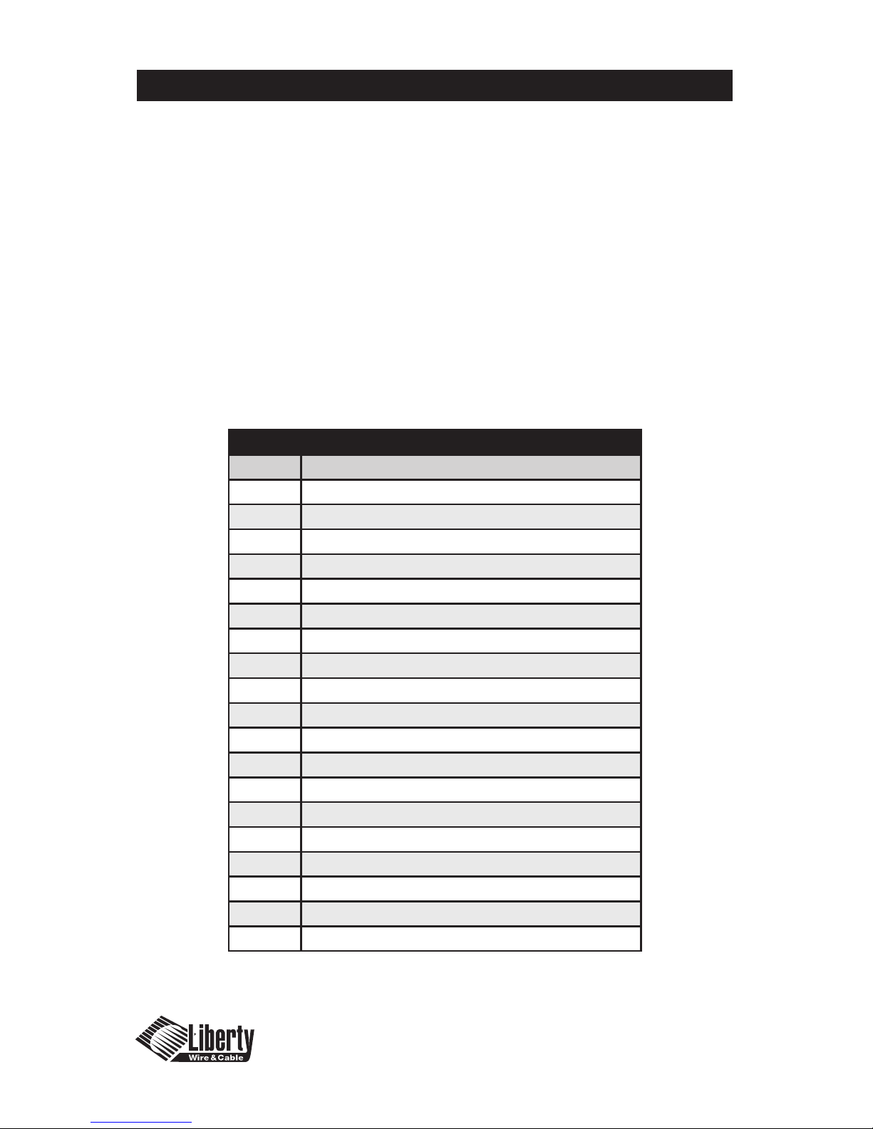
Connector pin assignment for HDMI Type A receptacle
Pin # Description
1 TMDS Data 2 +
2 TMDS Data 2 shield
3 TMDS Data 2 -
4 TMDS Data 1 +
5 TMDS Data 1 shield
6 TMDS Data 1 -
7 TMDS Data 0 +
8 TMDS Data 0 shield
9 TMDS Data 0 -
10 TMDS Clock +
11 TMDS Clock shield
12 TMDS Clock -
13 CEC
14 RESERVED
15 SCL
16 DDC DATA
17 DDC/CEC GROUND
18 +5VDC POWER
19 HOT PLUG DETECT
12 TMDS Clock -
13 CEC
14 RESERVED
15 SCL
16 DDC DATA
17 DDC/CEC GROUND
18 +5VDC POWER
19 HOT PLUG DETECT
Page 11

1-10
Warranty Information
1 (One) Year Warranty
Liberty Wire & Cable warrants this Digitalinx™ Fiber Optic Extender to be free
from defects in workmanship and materials, under normal use and service, for
a period of one (1) year from the date of purchase from Liberty Wire & Cable or
its authorized resellers.
If a product does not work as warranted during the applicable warranty period,
Liberty Wire & Cable shall, at its option and expense, repair the defective
product or part, deliver to the customer an equivalent product or part to
replace the defective item, or refund the customer the purchase price paid for
the defective product.
All products that are replaced will become the property of Liberty Wire &
Cable. Replacement products may be new or reconditioned.
Any replaced or repaired product or part has a ninety (90) day warranty or the
remainder of the initial warranty period, whichever is longer.
Liberty Wire & Cable shall not be responsible for any software, rmware,
information, or memory data loss of customer contained in, stored on, or
integrated with any products returned to Liberty Wire & Cable for repair under
warranty or not.
Warranty Limitation and Exclusion
Liberty Wire & Cable shall have no further obligation under the foregoing
limited warranty if the product has been damaged due to abuse, misuse,
neglect, accident, unusual physical or electrical stress, unauthorized
modications, tampering, alterations, or service other than by Liberty Wire &
Cable or its authorized agents, causes other than from ordinary use of failure to
properly use the product in the application for which said product is intended.
Warranty Information
Page 12
1-11
Troubleshooting
The Digitalinx™ Fiber Optic Extender is designed for years of trouble free
service, please reference the troubleshooting chart below if experiencing
issues with the device.
Troubleshooting/Customer Service
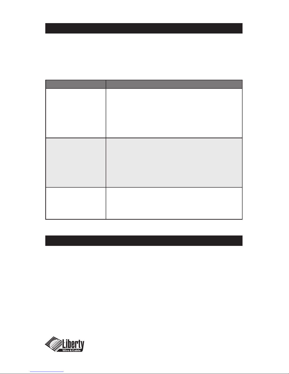
Symptom Solution
Black Screen 1.) Check all AC and DC plugs for Connectivity, Ensure all power
LED’s are indicating power is present. Check RJ45 plugs to
ensure connectivity.
2.) Ensure the TX unit is plugged into the source and the RX unit
is plugged into the Display.
3.) Ensure the Status LED is green on both units.
4.) Check the Source and Display to ensure they are operating
properly and powered correctly.
Image Distorted or
Displaying Digital
Articles and Noise
1.) Ensure the resolution is set correctly between source
and display. The resolution must be less then or equal to
UXGA@60HZ.
2.) Reboot the system in the correct sequence shown in the
installation section of the manual.
3.) Power down, disconnect and reconnect the optical
connections and DC power adapters and power back up in
the correct sequence.
No illumination
Status LED
1.) Check Polarity of LC Plugs. Visually check ber color codes to
ensure LC cables were built correctly. A-A, B-B etc.
2.) Power down units and clean Fiber receptacles, LC end faces.
Reconnect and power back up in correct sequence shown in
installation section.
Customer Service
Liberty Wire and Cable
11675 Ridgeline Drive
Colorado Springs, CO 80921
If you have issues, questions, or require assistance with the use of this
device please contact Liberty Wire and Cable with any of the following
contact points:
Phone: (800) 530-8998 and ask for
technical assistance.
Email: [email protected] and indicate
in Subject Line “Technical Assistance”
Page 13

© 2007 Liberty Wire & Cable. All Rights Reserved.
Liberty Wire & Cable
11675 Ridgeline Drive
Colorado Springs, CO 80921
800-530-8998
www.libertycable.com
 Loading...