

Page 1
DL-AS21C Installation Guide
The DigitaLinx DL-AS21C is a compact multi-format switcher with
support for video resolutions up to UHD (4096x2160). Featuring
one HDMI input and one VGA input with stereo audio, the DL-AS21C
automatically or manually switches either input to a single HDMI
output.
The DL-AS21C features multiple methods of control. When set to Auto,
the switcher will automatically switch to the newest source device
added to the DL-AS21C with VGA taking precedence should multiple
sources be live simultaneously. The DL-AS21C may be manually
controlled by switching via the front panel, RS232, or contact closure.
As an added benefit, the DL-AS21C features a built-in CEC controller
to power on/off the connected display by auto-selecting the source
device’s status.
Page 2

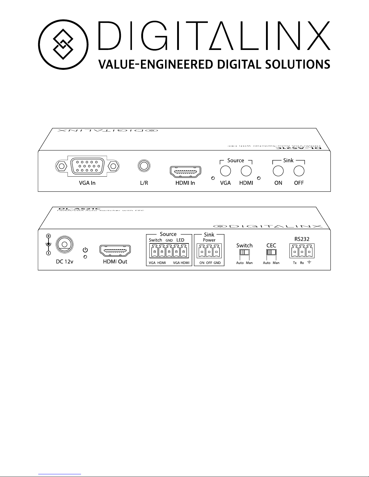
Front Panel
Rear Panel
A
B
D
E F G
C
2 31 4 5 6 7 8
A. VGA Input
B. Analog Audio Input (VGA only)
C. HDMI Input with Embedded Audio
D. VGA Select Button with LED
E. HDMI Select Button with LED
F. Sink (Display) On Button
G. Sink (Display) Off Button
1. 12v DC Input
2. Power LED
3. HDMI Output with Embedded Audio
4. Source Select Contact Closures with LED Indicators
5. CEC On/Off Contact Closures
6. Switch Mode Selector
7. CEC Mode Switch
8. RS232 Control
Included Accessories
• Installation guide
• Power supply with AC adapter (US)
• Mounting “L” brackets (2 ea)
• Mounting screws (4 ea)
• 3-pole terminal blocks (2 ea)
• 5-pole terminal block (1 ea)
Page 3

1. Verify all components included with the product are present before
installation.
2. Turn off power and disconnect the audio/video equipment by
following the manufacturer’s instructions.
3. Connect an HDMI cable between the digital source and an available
input on the DL-AS21C.
4. Connect a VGA cable between the analog source and the VGA input.
5. Connect an audio cable with 3.5 mm end between the analog source
and the analog audio input. Audio will not pass without a video
signal present.
6. Connect an HDMI cable between the display and the HDMI output.
7. Connect the appropriate audio output cable to any of the available
audio output ports of the DL-AS21C.
8. Connect an RS232 cable between a control device and the RS232
port.
9. Connect switches and LEDs to the Source and CEC contact closure
connections.
10. Connect the included power supply to the DL-AS21C and lock the
power supply to the power connector by twisting the locking collar
clockwise.
11. Power on all audio/video devices.
Installation Instructions
Contact Closure Wiring
HDMI LED +
VGA LED +
Ground for all connections
HDMI contact closure
VGA contact closure
Ground for all connections
CEC O
CEC On
LED connections will indicate selected
source input.
CEC connections allows remote access to
manually turn on and off a CEC enabled
display.
Contact closure connections will manually
switch source input.
Page 4

Input Selection
Display On/Off
Manual Switching:
Automatic Switching:
Automatic display off:
Automatic display on:
Manual display on/off:
To enable automatic switching, slide the Switch mode selector switch to the Auto
position. When in auto-switch mode, the DL-AS21C will switch according to the
following rules:
New Input: Upon detecting a new input, the switcher will automatically select the new
input.
Reboot: Once power is restored to the switcher, it will automatically reconnect the
active input. If both inputs are active, it will switch to the VGA input.
Source Removed: When an active source is removed, the DL-AS21C will switch to the
first available active input.
To enable manual switching, slide the Switch mode selector switch to the Man position.
When in manual switch mode, the select the input of the DL-AS21C by using one of the
following methods:
Front Panel: Press either the HDMI or VGA buttons.
Contact Closure: Make a contact closure between the HDMI and GND contacts or the
VGA and ground contacts.
RS232: Transmit the SET HDMI or SET VGA RS232 commands.
To automatically turn off the display when no active input is connected, slide the CEC
mode switch to the Auto position. When in Auto mode, the DL-AS21C will turn off the
display after no sources have been connected for three (3) minutes. To increase the
time before power off, send the CEC OFF XX command via RS232.
To automatically turn on the display when an active input is connected, slide the CEC
mode switch to the Auto position. When in Auto mode, the DL-AS21C will turn on the
display once an active source has been connected.
To manually turn on or off the display, slide the CEC mode switch to the Man position.
When in Man mode, the DL-AS21C can turn on and off the display with active sources
connected to the inputs.
Front Panel: Press either the ON or OFF buttons.
Contact Closure: Make a contact closure between the ON and GND contacts or the OFF
and ground contacts.
RS232: Transmit the DISPLAY ON or DISPLAY OFF RS232 commands.
Page 5
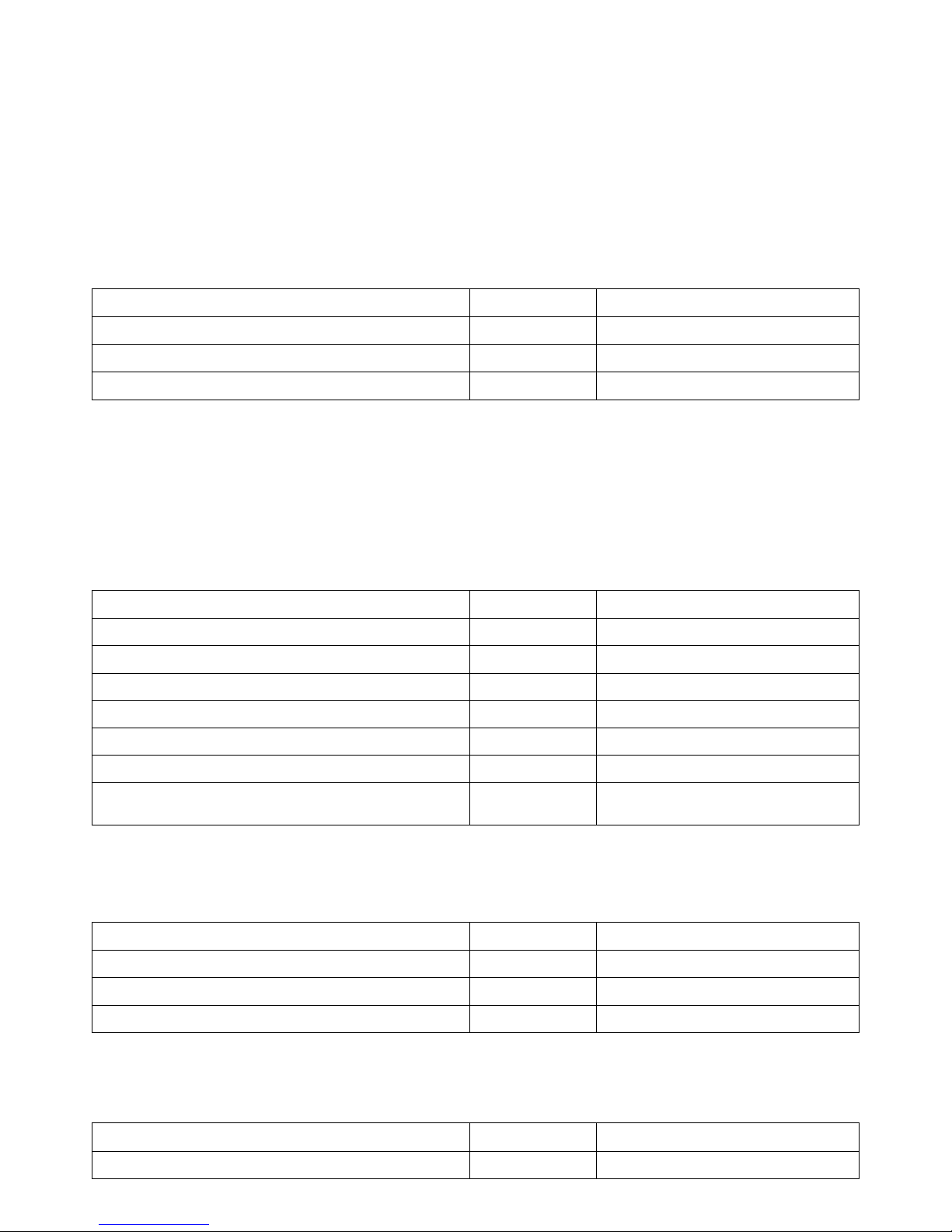
The EDID for the HDMI input is passed directly from the display.
RS232 Control
Input Switching
VGA EDID Settings
CEC Commands
Factory Reset
HDMI EDID
RS232 Settings: 9600 baud, 8 Data bits, 1 Stop bit, Parity = None
A carriage return and line feed must follow all RS232 commands. A carriage return and
line feed will follow all responses.
Description Command Response
Switch to HDMI Input
SET HDMI HDMI
Switch to VGA input
SET VGA VGA
Get active input
GET INPUT
HDMI or VGA
Description Command Response
1920x1080/60 (Full HD)
EDID FHD FHD
1280x720/60 (HD)
EDID HD HD
1920x1200/60 (WUXGA)
EDID WUXGA WUXGA
1600x1200/60 (UXGA)
EDID UXGA UXGA
1280x800/60 (WXGA)
EDID WXGA WXGA
1024x768/60 (XGA)
EDID XGA XGA
Get VGA EDID
GET EDID the current value is:
EDID
Description Command Response
Turn display (sink) on
DISPLAY ON DISPLAY ON
Turn display (sink) off
DISPLAY OFF DISPLAY OFF
Set CEC auto off time (XX = minutes) (default = 03)
CEC OFF XX CEC OFF Delay XX minutes
Description Command Response
Reset to factory defaults (VGA at FHD; CEC at 3 mins)
RST Reset to Factory defaults
Page 6

Important notice:
• Do not attempt to disassemble or alter the housing. There are no user-serviceable parts
inside the unit. Doing so will void your warranty.
• To minimize the possibility of equipment damage from electrostatic discharge (ESD), all
source and destination equipment must be powered off during installation.
• Do not connect the device to a telecommunication outlet wired to unrelated equipment.
Doing so may damage the unit or any connected equipment. Ensure all connected twisted pair
cabling is straight-through (point-to-point).
• Allow proper ventilation to reduce the risk of thermal failure.
Page 7
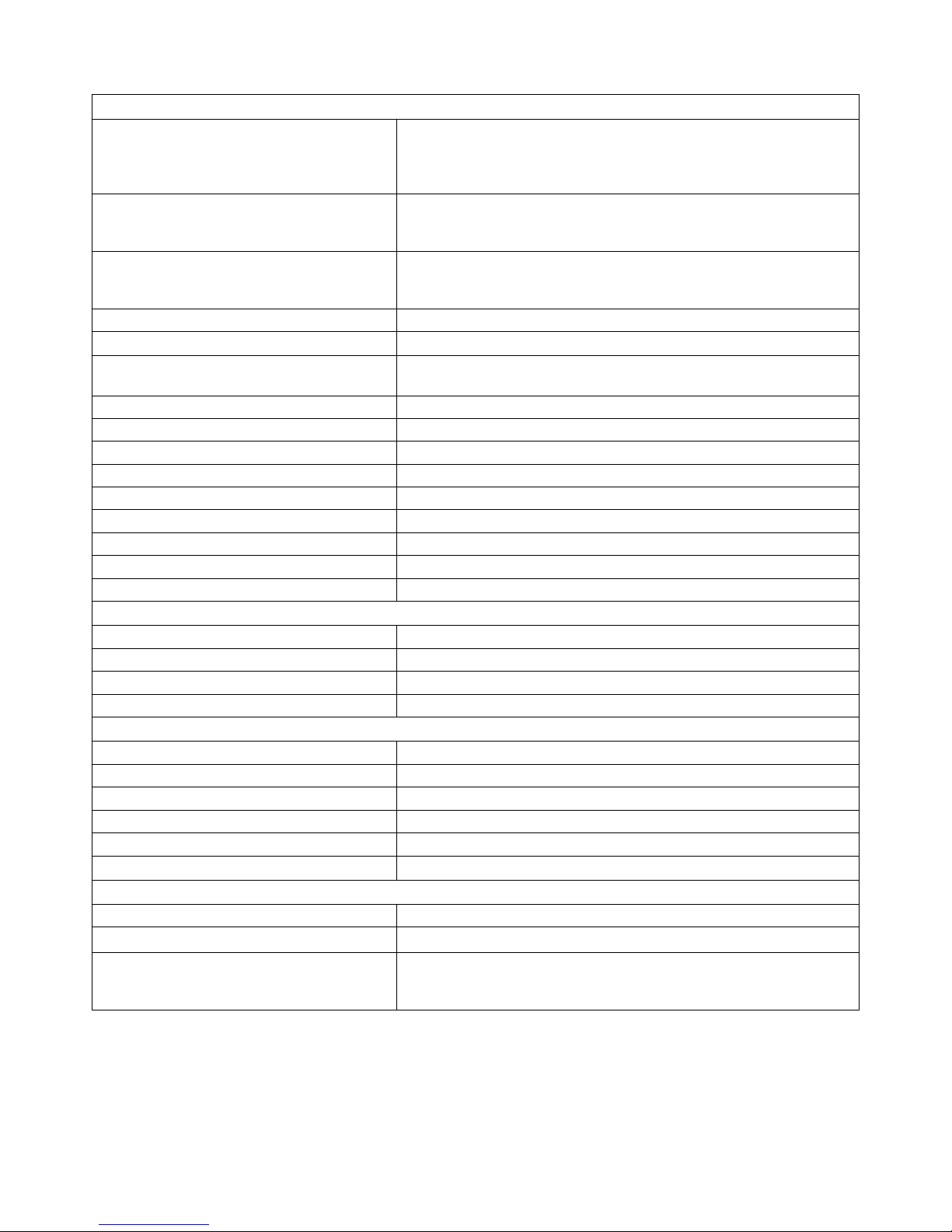
Technical Specifications
Supported Audio, Video, and Control
Supported Broadcast HDMI Input
Resolutions
480p: 59.94/60 Hz, 576p: 50 Hz, 720p: 25/29.97/30/50/59.94/60
Hz; 1080i: 50/59.94/60 Hz; 1080p: 23.98/24/25/29.97/30
/50/59.94/60 Hz; 4096x2160/3840x2160: 24/25/30 Hz;
4096x2160/3840x2160 (4:2:0): 50/60 Hz
Supported DVI-based HDMI Input
Resolutions (all at 60 Hz)
640x480, 720x576, 800x600, 1024x768, 1280x720, 1280x800,
1280x1024, 1360x768, 1366x768, 1440x900, 1400x1050, 1600x900,
1600x1200, 1680x1050, 1920x1080, 1920x1200
Supported VGA Input Resolutions (all
at 60 Hz)
640x480, 720x576, 800x600, 1024x768, 1280x720, 1280x800,
1280x1024, 1360x768, 1366x768, 1440x900, 1400x1050, 1600x900,
1600x1200, 1680x1050, 1920x1080, 1920x1200
Video Compliance HDMI, HDCP
HDMI EDID Pass-through from Display
VGA EDID (set via RS232) 1024x768, 1280x720, 1280x800, 1600x1200, 1920x1080 (default),
1920x1200
Embedded Audio Input/Output PCM 2 channel; AAC 5.1
Analog Audio Frequency Response 20Hz-20KHz
Analog Audio Input Impedance >10k ohm
Analog Audio Output Impedance 50 ohm
Input DDC Signal 5.0 volts p-p (TTL)
Input Video Signal 0.5 to 1.0 volts p-p
Maximum Passive HDMI Distance 5 m (16 ft)
RS232 Baud Rate 9600 baud
CEC On and Off to display only
Chassis and Environmental
Enclosure Painted steel
Dimensions (H x W x D) 20 mm x 142 mm x 64 mm (0.78 in x 5.59 in x 2.52 in)
Operating Temperature (Environment) 0° to +40° C (+32° to +104° F)
Operating Humidity (Environment) 20% to 90%, Non-condensing
Power, ESD, and Regulatory
Maximum Power Consumption 3.8 watts
Power Supply Input Voltage 100-240v AC at 50/60 Hz at 0.45 A
Power Supply Output Rating 5V DC at 3 A
ESD Protection 15kV
Device Regulatory RoHS
Power Supply Regulatory CE, RoHS, UL, TUV, FCC
Other
Standard Warranty 2 Years
Diagnostic Indicators Power, Selected Input
Included Items Installation guide, power supply, AC adapter (US), three pole
terminal blocks (2 ea), five pole terminal blocks ( 1 ea), mounting
“L” brackets (2 ea), mounting screws (4 ea)
Distances and picture quality may be aected by cable grade, cable quality, source and desnaon equipment, RF
and electrical interference, and cable patches.
Page 8

rev 150724
11675 Ridgeline Dr.
Colorado Springs, CO 80921
Toll-Free: 800-530-8998
Fax: 719-260-0075
www.libav.com
 Loading...