

Page 1

-------------------------------------------------------------------------------------------------------------------------------------------------------------------------------------------------------------------------------------------------------------------------------------------------
--------------------------------------------------------------------------------------------------------------------------------------------------------------------------------------------------------------------------------------------------------------------------------------------------------------------------------------------------------------------------------------------------------------------------------------------------------------------------------------------------------------------------------------------------------------------------------------------------
MXS-EVO
Disciplined RF Generator
Rev 1.7
Page 2

MXS-EVO - MANUAL
-------------------------------------------------------------------------------------------------------------------------------------------------------------------------------------------------------------------------------------------------------------------------------------------------
MXS-EVO – Manual – Rev 1.7 - 2 -
Dichiarazione di conformità
Declaration of conformity
La Ditta
The Company
DIGITAL INSTRUMENTS S.r.l.
Via Parco degli Scout, 13
20091 BRESSO (MI) ITALY
Dichiara con la presente che il Prodotto
Herewith declares that the Product
Tipo / Type Disciplined RF Generator with Multiple Sources
Modello / Model MXS-EVO
Serial Number
0140 /
Oggetto di questa dichiarazione è conforme ai seguenti standard o norme della Comunità Europea
Referred to by this declaration is in conformity with the following standards or normative documents of EC
Norme Europee Armonizzate
European Armonized Standards
CEI EN 61000-6-4:2007
Electromagnetic compatibility (EMC) - Part 6-4: Generic standards Emission standard for industrial environments
CEI EN 61000-6-2:2006
Electromagnetic compatibility (EMC) - Part 6-2: Generic standards Immunity for industrial environments
CEI EN 55011:2011
Limits and methods of measurement of radio disturbance characteristics of
industrial, scientific and medical (ISM) radio-frequency equipment
CEI EN 61000-4-2:2011
Electromagnetic compatibility (EMC) - Part 4-2: Testing and measurement
techniques - Electrostatic discharge immunity test
CEI EN 61000-4-3:2007+A1:2009+A2:2011
Electromagnetic compatibility (EMC) - Part 4-3: Testing and measurement
techniques - Radiated, radio-frequency, electromagnetic field immunity test
CEI EN 61000-4-4:2006+A1:2010
Electromagnetic compatibility (EMC) – Part 4-4:Testing and measurement
techniques – Electrical fast transient/burst immunity test
CEI EN 61000-4-5:2007
Electromagnetic compatibility (EMC) - Part 4-5: Testing and measurement
techniques - Surge immunity test
CEI EN 61000-4-6:2011
Electromagnetic compatibility (EMC) - Part 4-6: Testing and measurement
techniques - Immunity to conducted disturbances, induced by radiofrequency fields
CEI EN 61000-4-8:1997+A1:2001
Electromagnetic compatibility (EMC) - Part 4-8: Testing and measurement
techniques - Power frequency magnetic field immunity test
CEI EN 61000-4-11:2010
Electromagnetic compatibility (EMC) - Part 4-11: Testing and measurement
techniques - Voltage dips, short interruptions and voltage variations
immunity tests
CEI EN 60204-1:2006+A1:2010
Safety of machinery - Electrical equipment of machines - Part 1: General
requirements
Bresso, October 2012
DIGITAL INSTRUMENTS S.r.l.
Via Parco degli Scout, 13
20091 BRESSO (MI) ITALY
Marco Genova
Quality Assurance Manager
Page 3

MXS-EVO - MANUAL
-------------------------------------------------------------------------------------------------------------------------------------------------------------------------------------------------------------------------------------------------------------------------------------------------
MXS-EVO – Manual – Rev 1.7 - 3 -
Istruzioni di sicurezza
Safety Instructions
Il dispositivo è stato progettato, costruito e collaudato in conformità alle normative richiamate nel Certificato di
Conformità ed è stato rilasciato dal costruttore completamente testato secondo gli standard di sicurezza. Per
mantenere questa condizione e assicurare la sicurezza d’uso, l’utente deve osservare tutte le istruzioni e
segnalazioni di pericolo descritte in questo manuale.
This unit has been designed and tested in accordance with the EC Certificate of Conformity and has left the
manufacurer’s plant in a condition fully complying with safety standard. To maintain this condition and to ensure safe
operation, the user must observe all the instructions and warnings given in this operating manual.
Prima di mettere in servizio il dispositivo, leggere attentamente ed integralmente le istruzioni per l’uso.
Osservarle e seguirle in tutti i punti. Provvedere in modo che le istruzioni per l’uso siano sempre
accessibili a tutti gli addetti.
Prior to switching on the unit, please read carefully the instructions on the manual. Keep this manual
available for all every user of this equipment.
Il terminale PE sul dispositivo deve essere connesso al conduttore PE prima di eseguire qualsiasi altra
connessione. L’installazione ed il cablaggio devono essere eseguiti da personale tecnico qualificato.
The PE terminal of the unit must first be connected to the PE conductor on site before any other connections
are made. Installation and cabling of the unit to be performed only by qualified technical personnel.
Lo strumento supporta alimentazione AC wide range da 95 Vac a 240 Vac e deve essere connesso
tramite protezione con corrente nominale massima pari a 16A.
This unit may be operate from wide range AC supply networks from 95 Vac to 240 Vac fused with max. 16A.
Lo strumento supporta alimentazione DC wide range da 20 Vdc a 50 Vdc e deve essere connesso
tramite protezione con corrente nominale massima pari a 5A. Il circuito di protezione contro
l’inversione di polarità è implementato a bordo.
This unit may be operate from wide range DC supply networks from 20 Vdc to 50Vdc fused with max.
5A.Circuit against polarity inversion is also implemented.
Le condizioni di sicurezza vanno testate ad ogni sostituzione. Ispezione visiva dei cavi, stato
dell’isolamento, corrente di dispersione, stato del connettore PE e test funzionale.
A safety test must be performed after each replacement of part. Visual inspections, PE conductor test,
insulation resistance, leakage-current measurement, functional test.
Non interrompere il conduttore PE in nessun caso. Un interruzione del cavo PE rende l’apparato
elettricamente pericoloso.
It is not permissible to interrupt PE conductor intentionally, neither in the incoming cable nor on the unit
itself as this may cause the unit become electrically hazardous.
Ogni riparazione, manutenzione e sostituzione del dispositivo deve essere eseguita unicamente da
personale autorizzato dalla Digital Instruments.
Any adjustments, replacements of parts, maintenance or repair may be carried out only by authorized Digital
Instruments technical personnel.
Assicurarsi che ogni collegamento con dispositivi informatici sia eseguito secondo IEA950/EN60950
Ensure that the connections with information technology equipment comply with IEC950/EN60950
Page 4
MXS-EVO - MANUAL
-------------------------------------------------------------------------------------------------------------------------------------------------------------------------------------------------------------------------------------------------------------------------------------------------
MXS-EVO – Manual – Rev 1.7 - 4 -
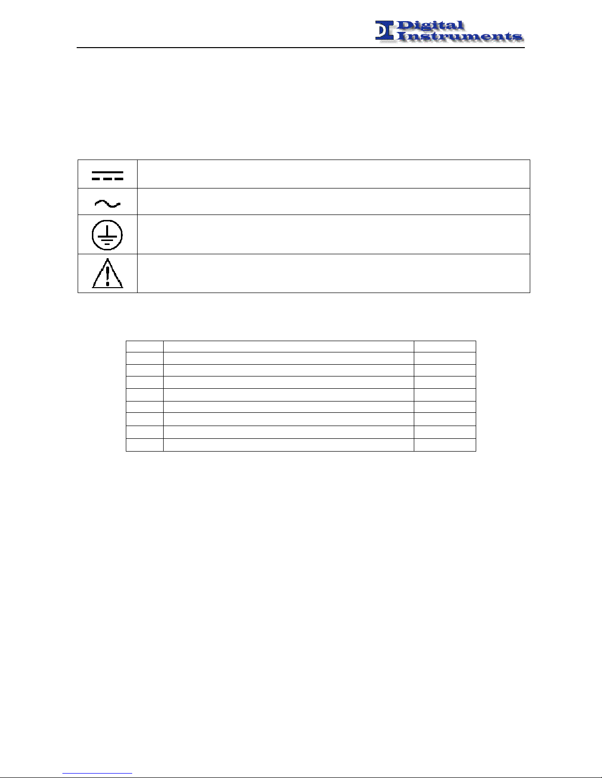
Simboli di sicurezza
Safety Symbols
Sono presenti sul dispositivo e nella documentazione simboli utilizzati per la segnalazione di segnalazione
conformi alle specifiche IEC61010-1 II.
Safety-related symbols used on equipment and documentation comply with IEC 61010-1 II.
• SIMBOLO DIRECT CURRENT IEC 417, N°5031
Vdc may be used on rating labels
• SIMBOLO ALTERNATING CURRENT IEC 417, N°5032
For rating labels, the symbol is typically replaced by V and Hz as in 230V, 50Hz.
• SIMBOLO PROTECTIVE CONDUCTOR TERMINAL IEC 417, N°5019
This symbol is specifically reserved for the
PROTECTIVE CONDUCTOR TERMINAL
and no other. It is
placed at the equipment earthing point and is mandatory for all grounded equipment
• SIMBOLO CAUTION ISO 3864, N°B.3.1
used to direct the user to the instruction manual where it is necessary to follow certain
specified instructions where safety is involved.
Changelog
Rev. Note Data
1.0 First revision 30/11/2011
1.1 Updated and fixed revision 16/03/2012
1.2 Added programmable outputs details 11/04/2012
1.3 Added note about the internal NTP server 18/04/2012
1.4 Added section about Custom Settings 30/10/2012
1.5 Updated changelog 02/05/2013
1.6 Added notes about the NTP server timestamping 14/10/2013
1.7 Added FAQ section 31/10/2013
Page 5

MXS-EVO - MANUAL
-------------------------------------------------------------------------------------------------------------------------------------------------------------------------------------------------------------------------------------------------------------------------------------------------
MXS-EVO – Manual – Rev 1.7 - 5 -
MXS-EVO
Disciplined RF Generator with Multiple Sources
Index
Summary ....................................................................................................................................................................... 6
Front View..................................................................................................................................................................... 7
Rear View ...................................................................................................................................................................... 7
Connectors details......................................................................................................................................................... 8
Main Operation........................................................................................................................................................... 10
GPS........................................................................................................................................................................... 10
External Reference (EXT) ........................................................................................................................................ 10
E1.............................................................................................................................................................................. 10
NTP........................................................................................................................................................................... 12
PTP (IEEE 1588) ...................................................................................................................................................... 13
IRIG-B ...................................................................................................................................................................... 14
Date and time .............................................................................................................................................................. 15
Switchover Function ................................................................................................................................................... 16
Switch Policies.......................................................................................................................................................... 16
Switchover Treshold ................................................................................................................................................. 16
Graph Menu ................................................................................................................................................................ 19
WEB Interface ............................................................................................................................................................ 22
Event Log ................................................................................................................................................................. 30
SNMP Trap Management ......................................................................................................................................... 31
User Account ............................................................................................................................................................ 31
Custom Settings .......................................................................................................................................................... 32
First Run...................................................................................................................................................................... 33
Appendix A: Quality Factor ...................................................................................................................................... 35
General Review ........................................................................................................................................................ 35
GPS antenna positioning........................................................................................................................................... 35
Quality Factor ........................................................................................................................................................... 36
Statistics.................................................................................................................................................................... 37
Automatic Site Survey .............................................................................................................................................. 37
Appendix B: FAQ ....................................................................................................................................................... 38
Appendix C: Changelog ............................................................................................................................................. 41
Assistance .................................................................................................................................................................... 43
Technical Data ............................................................................................................................................................ 44
Page 6

MXS-EVO - MANUAL
-------------------------------------------------------------------------------------------------------------------------------------------------------------------------------------------------------------------------------------------------------------------------------------------------
MXS-EVO – Manual – Rev 1.7 - 6 -
Summary
This manual provides to the user of the apparatus MXS-EVO all the information necessary for proper operation. The
informations include the normal installation procedures and any data on the maintenance and programming in order to
facilitate interventions in the field.
MXS-EVO is a multiple output signal generator able to reconstruct stable time-frequency references (10MHz, PPS,
2.048MHz, E1, IRIG-B).
It is composed of a GPS receiver and accepts in input a frequency RF signal, a timing RF signal, an E1 multiframe
signal and an IRIG-B signal. It is possibile to use any or all of these references tot une the internal high stability OCXO.
In the standard version there are 12 independent programmable outputs in any of the possible configurations (10 MHz,
PPS, 2.048 MHz, E1, IRIG-B AM, IRIG-B DC), 1 E1 input and 1 E1 output, 1 time input and 1 frequency input, 1
optical IRIG-B input, 1 optical IRIG-B output, 1 TTL IRIG-B input (may be used in place of the external timing input).
MXS-EVO is a very flexible solution suited to all those applications where is necessari to provide a stable timefrequency reference to multiple devices. whilst mantaining electrical isolation.
When an error on the selected source is observed an error condition is generated via SNMP and dry contacts and a new
source is selected between the available ones as per user configured priority.
MXS-EVO is quite simple to use and to set-up. Every function can be accessed locally from the LCD panel and
remotely via WEB or SNMP.
MXS-EVO gives informations about its internal status via 7dry contacts placed on the rear panel and the LEDs on the
front panel.
MXS-EVO has double Power Supply Unit, to ensure best safety and uninterrupted work.
MXS-EVO is in metallic box of sizes 1U 19’’for rack installation.
Note
This document may contain confidential and or reserved material of property of Digital Instruments S.r.l. It cannot
be reproduced, used or shown to third parties for any other scope than the intended one.
WARNING: Before inserting the power supply please carefully read all instructions for proper
installation.
Page 7
MXS-EVO - MANUAL
-------------------------------------------------------------------------------------------------------------------------------------------------------------------------------------------------------------------------------------------------------------------------------------------------
MXS-EVO – Manual – Rev 1.7 - 7 -
Front View
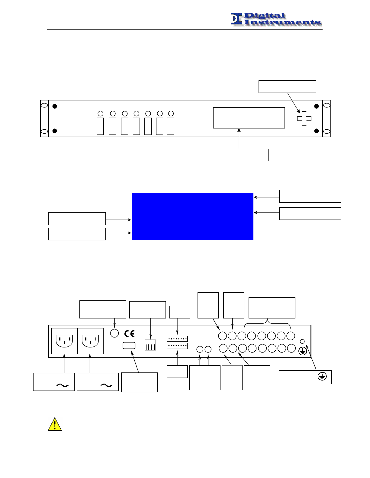
The front panel appears as shown in the following figure.
On the left side there are the two removable modules, whilst on the right can be found an alphanumeric 20x4 display
and a keyboard.
In modo operativo sul display vengono visualizzati alcuni parametri come nell’esempio sotto:
By pushing the right keyboard button it’s possible to enter the main menu of the MXS-EVO.
Rear View
In the following feature is depicted the back of the apparatus MXS-EVO with the position of connectors.
The MXS-EVO does not provide any supply switch.
Digital MXS-EVO
Instruments 1.1
IRG PTP E1 EXT[GPS]
23/01/12 16:21:29
Device name
Product version
Date and time
Selected source
Keyboard
RS-232
Connettor
TNC Antenna
GPS
TLC
PE Terminal
Programmable
Outputs
TLS
Ethernet
Connettor
Left Power
Supply
Alphanumeric Display
Right Power
Supply
BNC
E1
Rx
OUT IN
Optical
IRIG-B
BNC
EXT
Time
BNC
EXT
Freq
E1 / T1
EXT
GPS
PWR R
PWR L
IRIG
PTP
BNC
E1
Tx
Page 8

MXS-EVO - MANUAL
-------------------------------------------------------------------------------------------------------------------------------------------------------------------------------------------------------------------------------------------------------------------------------------------------
MXS-EVO – Manual – Rev 1.7 - 8 -
Connectors details
TLS connector (Remote signals)
1
The 8 poles TLS connector provides the following information on the various pins (from left to right):
PIN 1: Common contact
PIN 2: Closed contact Right power supply provided
PIN 3: Closed contact Left power supply provided
PIN 4: Closed contact GPS reference present and valid
PIN 5: Closed contact EXT reference present and valid
PIN 6: Closed contact E1 reference present and valid
PIN 7: Closed contact PTP reference present and valid
PIN 8: Closed contact Synchronization completed
TLC connector (Remote controls)
1
The 8 poles TCL connector provides the following commands on the various pins (from left to right):
PIN 1-2: Closed contact Manual switch
PIN 3-4: Closed contact Automatic switch
PIN 5-6: Closed contact Switch over previous reference
PIN 7-8: Closed contact Switch over next reference
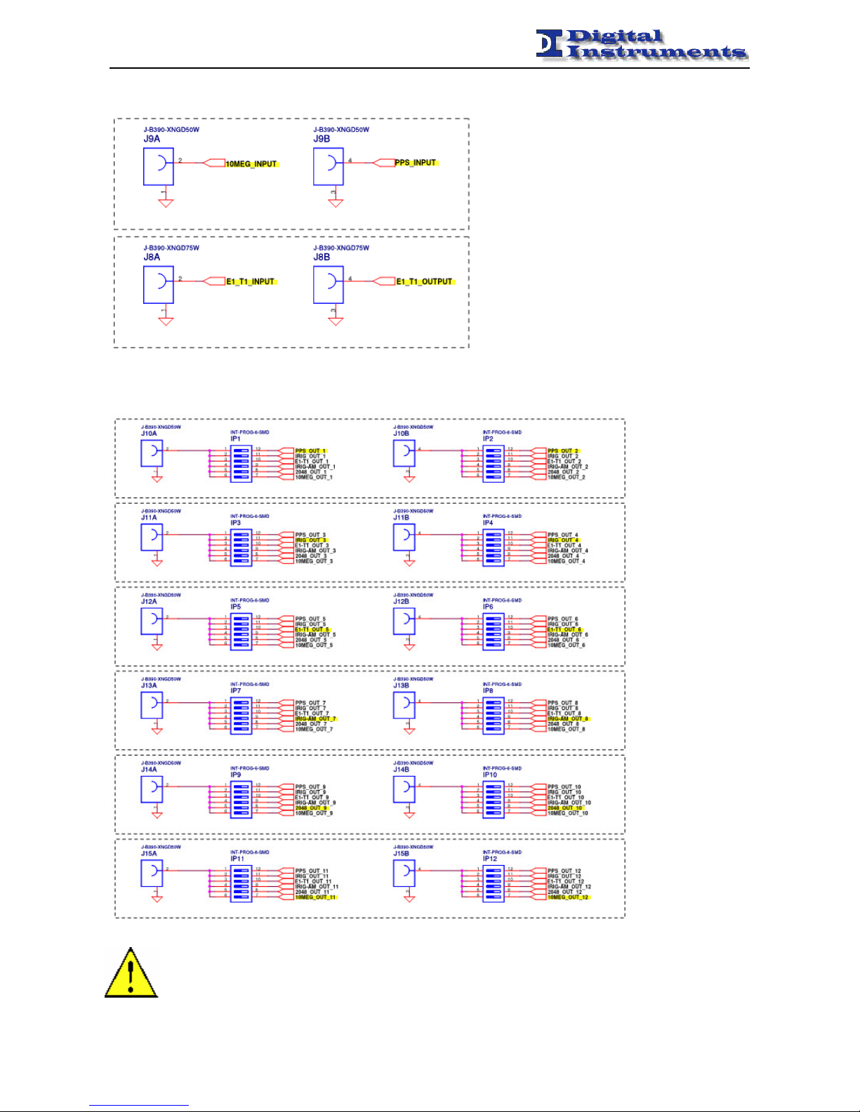
Programmable outputs
A tecnhical sheet about the programmable outputs is given alongside the device.
The following table can be taken as reference to understand it.
J8A 1A J9A 1B J10A 1C J11A 1D J12A 1E J13A 1F J14A 1G J15A 1H
J8B 2A J9B 2B J10B 2C J11B 2D J12B 2E J13B 2F J14B 2G J15B 2H
1A 1B 1C 1D 1E 1F 1G 1H
2A 2B 2C 2D 2E 2F 2G 2H
Page 9
MXS-EVO - MANUAL
-------------------------------------------------------------------------------------------------------------------------------------------------------------------------------------------------------------------------------------------------------------------------------------------------
MXS-EVO – Manual – Rev 1.7 - 9 -
Four connectors have fixed functions that cannot be altered:
Twelve connectors have instead customizable functions by means of a DIP switch matrix placed on the PCB inside the
device:
Even if modifying the outputs is simple is suggested to first contact the
factory in order to avoid voiding the warranty by opening the device.
Page 10

MXS-EVO - MANUAL
-------------------------------------------------------------------------------------------------------------------------------------------------------------------------------------------------------------------------------------------------------------------------------------------------
MXS-EVO – Manual – Rev 1.7 - 10 -
Main Operation
The main purpose of the MXS-EVO is to provide stable output signals of Time (PPS, E1, IRIG code, NTP/PTP) and
Frequency (10 MHz, 2.048MHz), and to enable the synchronization of the network.
This is allowed by the application of algorithms, tuning an high-stability internal oscillator.
Peculiarities of the ETS-EVO is the possibility to accept input from four different sources:
1. GPS
2. EXTERNAL REFERENCE
3. E1
4. PTP (IEEE 1588)
5. IRIG-B
In this manner it is possible to switch from one source to another, if a fault occurs.
The strong difference between the various sources is a major strength as it makes the same apparatus both very flexible
to suit the needs of the customer and very strong in order to better cope with possible failures of a type of source (for
example, the loss of accuracy of the GPS signal).
Even in case of a switch, references of Time / Frequency provided are kept stables.
GPS
The apparatus is internally equipped with a GPS receiver especially suitable for use as a time reference. The GPS
receiver is able to reproduce the local PPS signal relative to UTC second with a precision of typically ± 100 ns. With
this feature is possible to regulate the internal oscillator apparatus for producing a high-stability output signals.
External Reference (EXT)
The MXS-EVO accepts a frequency input and a timing input on two distinct BNC connectors.
These are the frequencies recognized:
• 1MHz
• 2MHz
• 2.048MHz
• 5 MHZ
• 10 MHz
This are the timing values recognized:
• 1 PPS
The device, when using the external frequency reference as source generates the internal PPS based on the last received
timing pulse from another reference.
It is possible to tune the internal OCXO in phase (slower, but keeping phase alignment) or in frequency (much faster,
but the phase alignment is lost). With the timing input only the phase disciplinino mode is supported.
This behaviour can be set under Disciplining Mode.
When both a frequency and time references are given, the latter ha more priority and is automatically chosen to mantain
a phase alignment.
E1
The E1 signal, standardized by the European Conference of Postal and Telecommunications
Administrations (CEPT) and subsequently adopted by the International Telecommunication Union
Telecommunication Standardization Sector (ITU-T), operates at a nominal value of 2.048 Mbps and
Page 11

MXS-EVO - MANUAL
-------------------------------------------------------------------------------------------------------------------------------------------------------------------------------------------------------------------------------------------------------------------------------------------------
MXS-EVO – Manual – Rev 1.7 - 11 -
is widely used in digital telecommunications worldwide, with the exception of USA and Canada
(where the T1 signal is in use) and Japan (where is in use the J1). The E1 link operates on two
separate coaxial cables (Rx and Tx).
Also in this case it’s possible perform a rapid frequency locking with the 2.048 MHz reference of
E1 signal, setting the Disciplining Mode voice to the frequency value.
Status Informations
MXS-EVO allows to view the status of the E1 module through the following values:
• Presence or absence of E1 signal
• Presence or absence of E1 framing
• SSM Quality (Rec. ITU-T G.704, see below) of the synchronization source
• Bit Error Rate is calculated by the BERT (see below)
• BERT Irq Array, binary array of interrupt requests that triggered errors generated in BERT (see below)
• Delay between the E1 PPS and the PPS generated by OCXO
Available Settings
MXS-EVO allows the possibility to set the device as a supplier of synchronization signal E1 (E1
Master), in case where it’s connected to valid synchronization sources (GPS, cesium oscillator,
etc.), or as a sevice receiver of E1 synchronization signal (E1 Slave). In the first case, it is also
possible to choose the quality of the source, according to the table of Recommendation G.704 (ITUT):
Quality
Level
Value
Displayed
Description of Sync Quality Level
0 Unknown Quality Unknown (existing synchronization network)
1 Reserved
2 G.811 Recommendation G.811
3 Reserved
4 SSU-A Synchronization Supply Unit A (Note 1)
5 Reserved
6 Reserved
7 Reserved
8 SSU- B Synchronization Supply Unit B (Note 1)
9 Reserved
10 Reserved
11 SETS Synchronous Equipment Timing Source (SETS)
12 Reserved
13 Reserved
14 Reserved
15 DON’T USE Do not use for synchronization
Note 1: In previous versions was used the terms "G.812 transit" and "G.812 local",
for more information, see Rec G.812 (ITU-T)
MXS-EVO allows to choose on which of the 30 (from 2 to 32, excluding 17) timeslots of the E1 frame transmit the
PPS signal. As default, the signal is sent and received on timeslot 32. The timeslots 1 and 17 are used to send sync and
control data by E1. The PPS is implemented by putting up only the LSB of the selected timeslot.
MXS-EVO allows to test the quality of the physical channel on which the E1 signal is transmitted activating the Bit
Page 12
MXS-EVO - MANUAL
-------------------------------------------------------------------------------------------------------------------------------------------------------------------------------------------------------------------------------------------------------------------------------------------------
MXS-EVO – Manual – Rev 1.7 - 12 -
Error Rate Test (in reception and / or transmission), and choosing which of timeslots (except for the one used for the
PPS and, advising against the first, where the sync data are sent) to receive and / or send the signal for the test. The form
of the Bit Error Rate Test can generate and detect pattern both pseudo-random and repetitive. It’s used to test and stress
the channels of communication data. Has been set the pseudo random pattern QRSS for testing. The apparatus allows to
show the value of the bit error rate and the log of interrupts that have generated errors in the BERT, the latter is defined
thus: 0X1X2X3X4X5X60 where:
• X1 passes from 0 to 1 occurs when the reception of an error;
• X2 passes from 0 to 1 when an overflow occurs in the counter total BERT;
• X3 goes from 0 to 1 when an overflow occurs on the BERT error counter;
• X4 changes from 0 to 1 when received 32 '1 'row;
• X5 goes from 0 to 1 when received 32 '0 'row;
• X6 from 0 to 1 when there is loss of synchronization;
MXS-EVO allows to choose which "column" (from 4 to 8) of bits use to transmit the value of the signal quality. By
default this value is sent and received on the column 8.
NTP
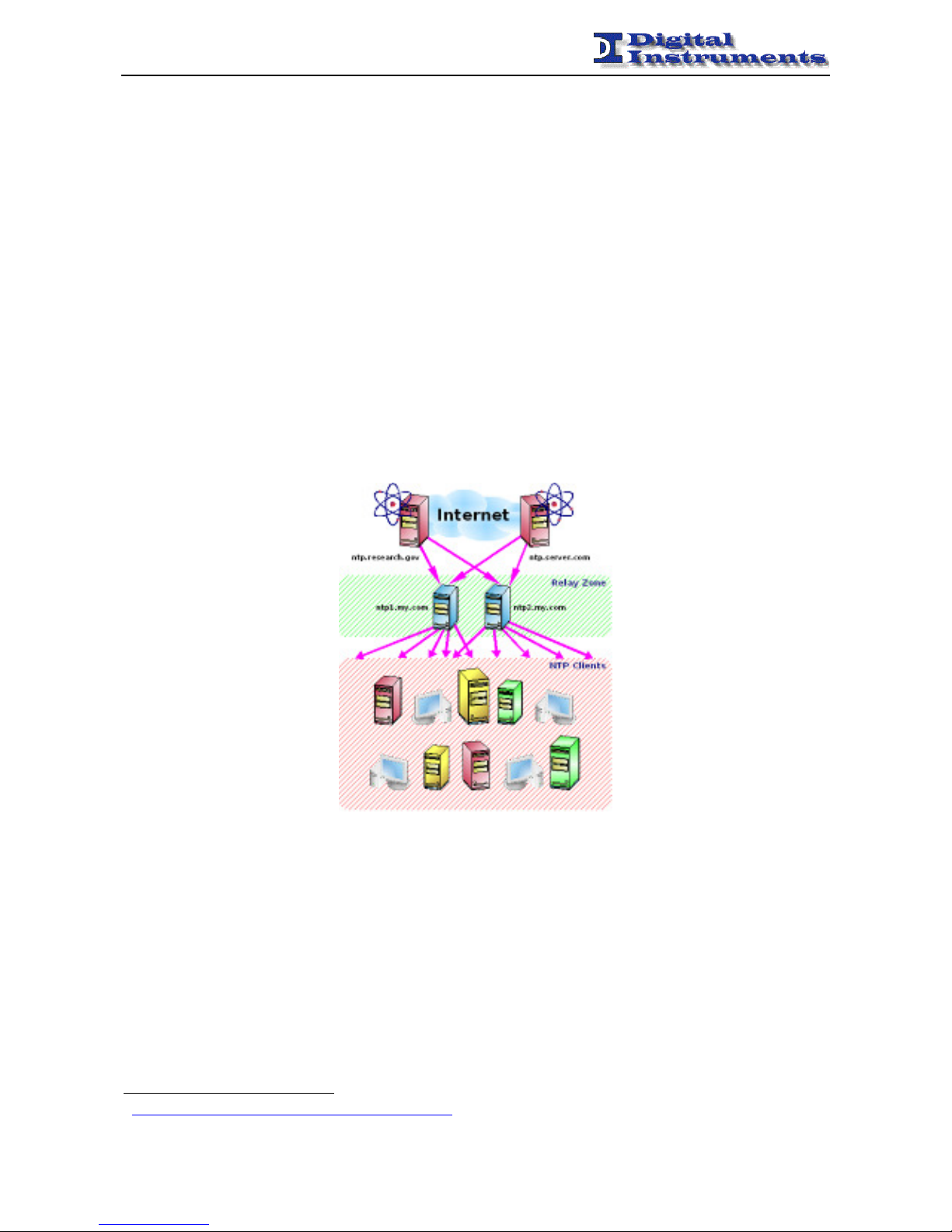
The NTP (Network Time Protocol) is a well-established standard for synchronization of PCs and other devices on the
Internet or an Intranet network.
The accuracy of the order of tens of milliseconds, can be considered adequate for most situations. Its flexibility and
strength, thanks to the many servers widely available, making it a very smart choice for time synchronization.
The device supports NTP server version 4 that distributes the synchronous time related to an external time reference
(typically GPS, PTP or IRIG-B).
To achieve better performance hardware timestamping is supported, but in this case PTP support is disabled.
When using hw timestamping the precision of the hardware timestamps in the NTP packet is better than 100 ns.
In order to use this feature the client has to support the interleaved mode1, enabled with the following statement:
peer <server ip> true iburst xleave prefer
In order to use the broadcast mode authentication has to be disabled in the client configuration with the following
statements:
disable auth
broadcastclient
1
http://www.eecis.udel.edu/~mills/ntp/html/xleave.html
Page 13
MXS-EVO - MANUAL
-------------------------------------------------------------------------------------------------------------------------------------------------------------------------------------------------------------------------------------------------------------------------------------------------
MXS-EVO – Manual – Rev 1.7 - 13 -
PTP (IEEE 1588)
The MXS-EVO supports the IEEE 1588-2008 (version 2), also known as Precision Time Protocol, both as master and
slave. When connected to an appropriate device compatible to the IEEE 1588 standard is able to synchronize the slave
apparatus with a precision well below the micro-second.
Note that using network switches non-compliant with IEEE 1588, variable delays in the order of some tens of
microseconds are introduced (as noted in the official website of the Protocol http://ieee1588.nist.gov/switch.htm).
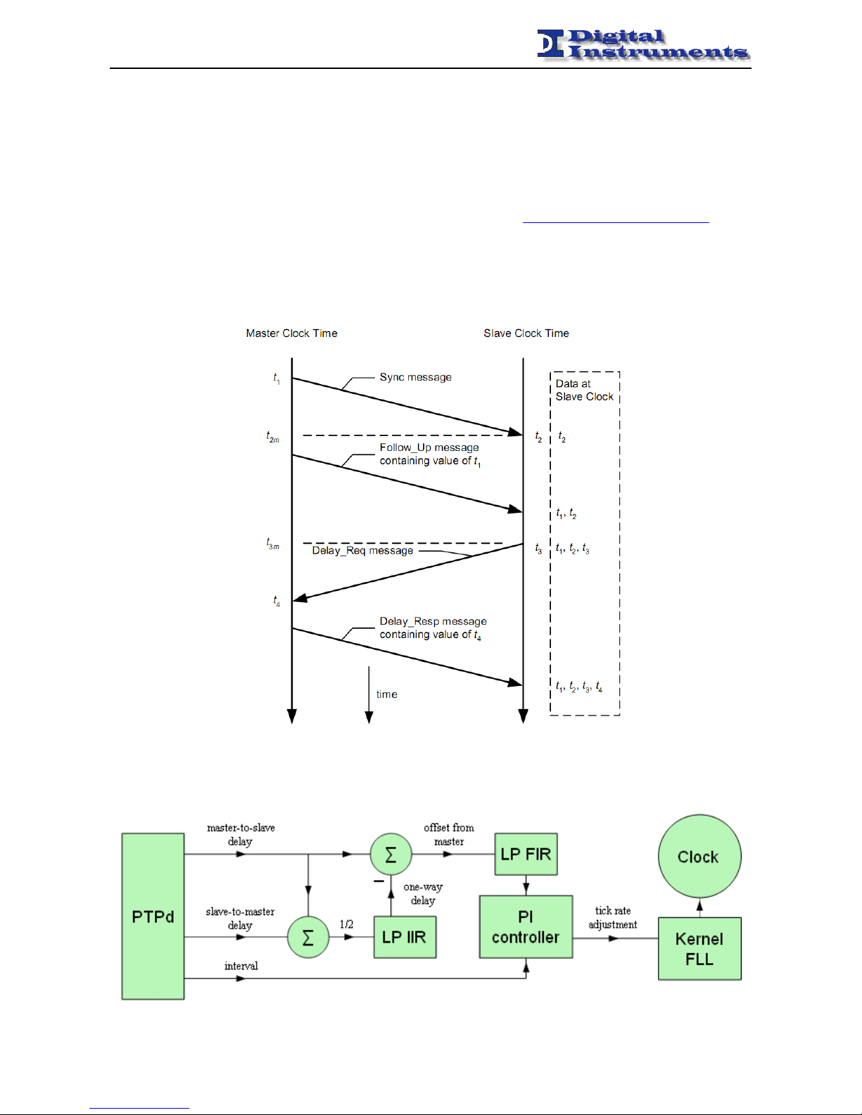
The IEEE 1588 bases its operation on the calculation of the transit time of PTP packets from the master to the slave
(and slave to master).
These latencies are calculated using a simple exchange of messages between master and slave that are associated with
timestamps managed at the hardware level.
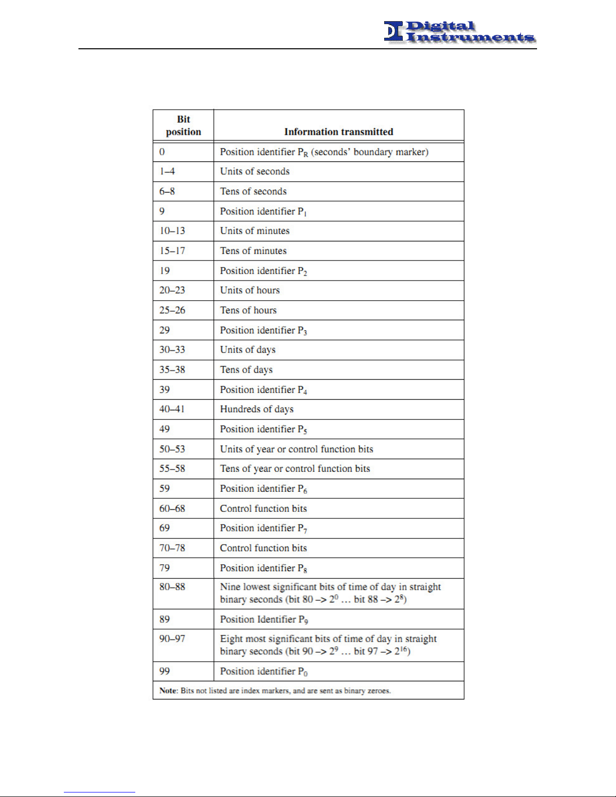
Once reconstructed the one-way-delay it is possible to use it to correct the clock of the slave and lock it to the master.
Below is shown the pattern of the loop relative to the clock tuning based on PTP.
Page 14
MXS-EVO - MANUAL
-------------------------------------------------------------------------------------------------------------------------------------------------------------------------------------------------------------------------------------------------------------------------------------------------
MXS-EVO – Manual – Rev 1.7 - 14 -
IRIG-B
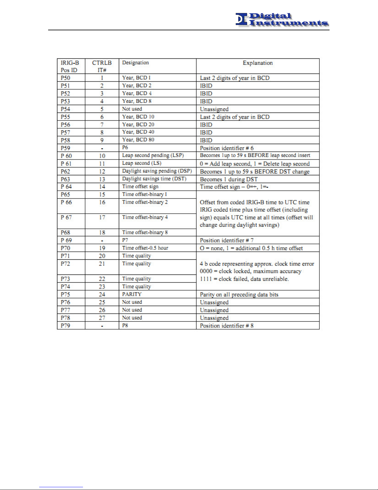
The device can accept in input and provide in output (on BNC and optical connectors) an IRIG-B stream of type 006,
compliant with following code:
Page 15
MXS-EVO - MANUAL
-------------------------------------------------------------------------------------------------------------------------------------------------------------------------------------------------------------------------------------------------------------------------------------------------
MXS-EVO – Manual – Rev 1.7 - 15 -
It was also implemented part of the standard 1344-1995. The offset compared to the UTC time can be set using the
Timezone of the apparatus. Changes of DST or leap second are not currently notified (always returned as 0).
The device can output both an IRIG-B DCLS and IRIG-B AM signals.
It can also recognize an IRIG-B DCLS signal via a BNC or optical connector.
When the BNC connector is used it inhibits the external timing input.
Date and time
The device disciplines its internal clock from the selected reference (GPS, PTP, IRIG-B, NTP) and distributes it with
the following rules:
• NTP (UTC timebase as per standard)
• PTP (TAI timebase as per standard)
Page 16

MXS-EVO - MANUAL
-------------------------------------------------------------------------------------------------------------------------------------------------------------------------------------------------------------------------------------------------------------------------------------------------
MXS-EVO – Manual – Rev 1.7 - 16 -
Switchover Function
ETS-EVO allows the possibility to switch the disciplining of its internal timebase selecting one of many sources.
This exchange can be configured to run automatically upon occurrence of an alarm condition, such as:
- PPS signal absence
- disconnection of the antenna
- error in the external source
- error in the E1 signal
- error in the PTP protocol
- error in the IRIG-B signal
In the log are reported the reason of the switch:
Mweb user defined switch from WEB
Msnmp user defined switch from SNMP
Mlcd user defined switch from LCD
Mopto user defined switch from TLC
Aser automatic switch due to serial connection lack of GPS
Aant automatic switch due to connection lack of GPS antenna
Apref automatic switch to the higher priority source
Aext automatic switch caused by an error in the external signal
Ae1 automatic switch caused by an error in the E1signal
Aptp automatic switch caused by errors in the PTP protocol
Airigb automatic switch caused by an error in the IRIG-B signal
Switch Policies
The MXS-EVO permits to chose the priorità of the various sources.
Priorità is bigger when the value is bigger. 0 inhibits the source.
When the device is configured for automatic switchover two different policies can be used:
Switch & Free
The device switch to the best available source when an error is recognized on the actually selected source.
Switch & Pref
The device always switch to the source with highest priority currenlty available, if valid.
In order to avoid the possibility of continuos alarms due to intermittent switches there is a check that does not permit to
switch more than 3 times in 5 minutes, by automatically lowering the policy (Switch & Pref Switch & Free).
This event has been given the following code:
Event Code 007 Switch Alarm Done more than 3 switches in less than 5 minutes
Switchover Treshold
This variable allows to define a time interval (in seconds) that must elapse between the time when an error has been
identified and when it will be exchanged effectively. If during this time the error will disappear, the exchange will be
deleted.
Page 17
MXS-EVO - MANUAL
-------------------------------------------------------------------------------------------------------------------------------------------------------------------------------------------------------------------------------------------------------------------------------------------------
MXS-EVO – Manual – Rev 1.7 - 17 -
Characterization of Sources
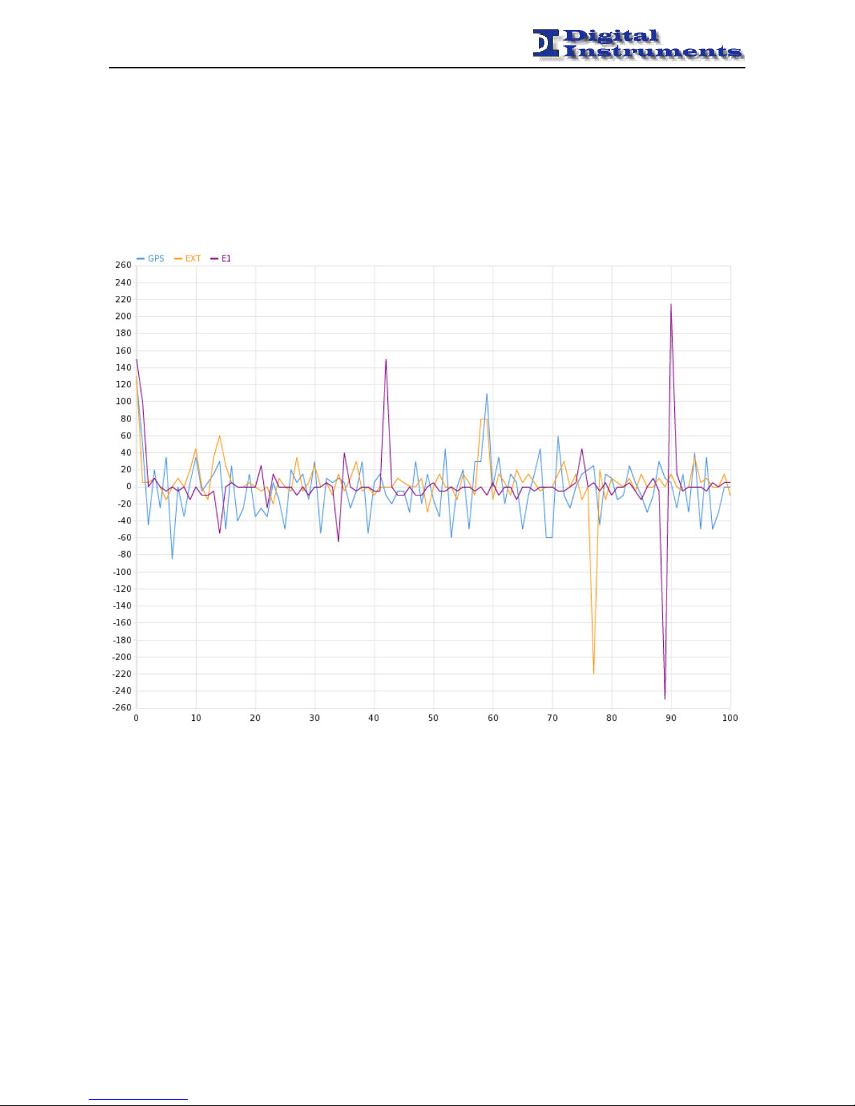
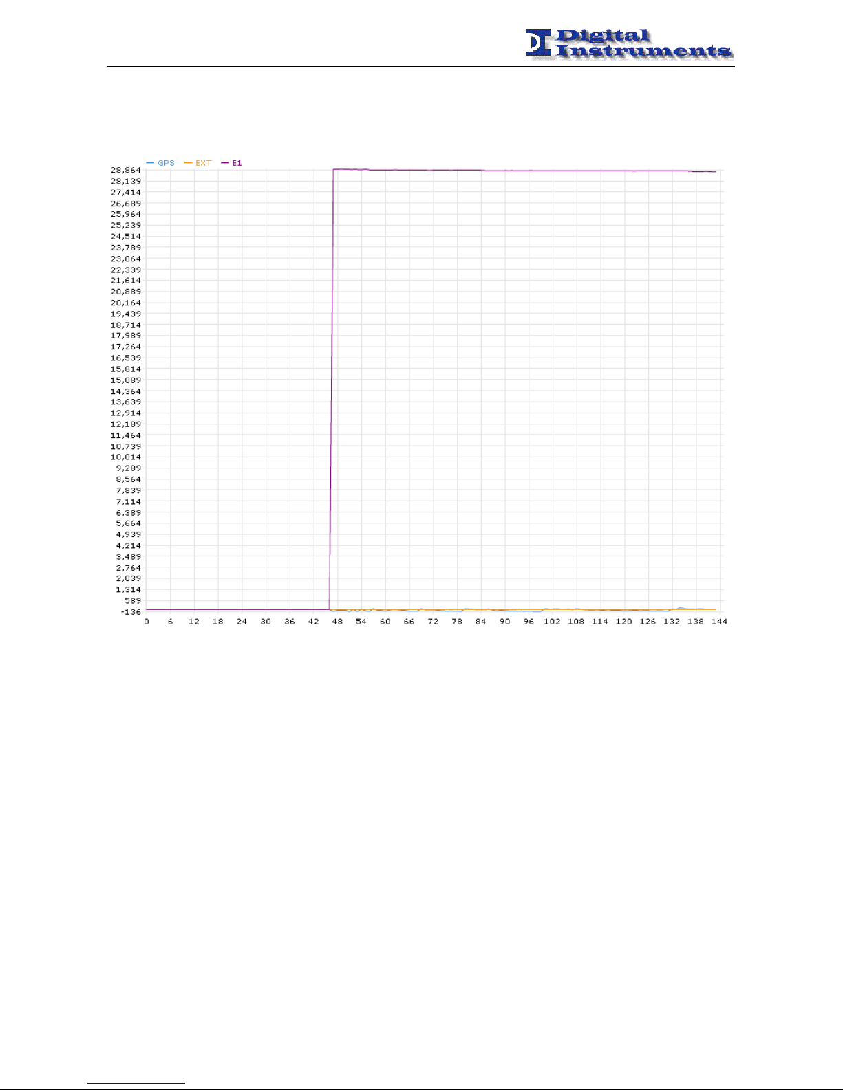
MXS-EVO was also designed to compare the quality of the different sources provided to apparatus, analyzing the ratio
∆f / f (variation of the frequency value on the nominal frequency) of each source. This analysis is supported by a graph
(that can be generated by the Stability Chart button in the Main Panel) which shows the trend of these ratios over time.
The step used is 5 minutes, while the values are expressed in nanoseconds.
Moreover, is also possible display both on web interface (the View section of Main Panel), and on the LCD screen
(below the status of each source), the delay, expressed in nanoseconds, between the PPS generated from the apparatus
output and the three different tuning sources.
To correctly perform the characterization of various sources it’s good configure the equipment with the following
settings:
• Manual mode exchange
• GPS Source selected
It’s good pratice also expect that the PPS generated by the radio is valid and that its delay is close to 0 ns (visible from
GPS status).
Page 18
MXS-EVO - MANUAL
-------------------------------------------------------------------------------------------------------------------------------------------------------------------------------------------------------------------------------------------------------------------------------------------------
MXS-EVO – Manual – Rev 1.7 - 18 -
It is also possible display the progress of these distances over time (using the button Distance Chart in the Main Panel).
Page 19

MXS-EVO - MANUAL
-------------------------------------------------------------------------------------------------------------------------------------------------------------------------------------------------------------------------------------------------------------------------------------------------
MXS-EVO – Manual – Rev 1.7 - 19 -
Graph Menu
The graph menu can be navigated with the pressing of the four direction provided by the keyboard.
To enter the first level from level zero (ROOT) is enough to press the RIGHT key, that works as Enter key. At this
point all the first level menus are visible in a cyclic loop with the pressing of the UP and DOWN keys. The currently
selected menu is recognized by an arrow placed on its left side. It is possible to enter it by pressing the RIGHT key.
By entering a menu is possible to view all of its associated submenus by pressing the UP and DOWN keys. The
RIGHT key permits, once again, to enter the selected submenu in the view mode. By pressing RIGHT again is
possible to modify the value of the parameter (an arrow indicates the modify mode). RIGHT (Enter) confirms the
choice, whilst LEFT (Escape) discards it.
The changing of parameters from front panel is only supported in local mode.
From the level 0 (ROOT) it is possible to change the contrast of the LCD screen by pushing the UP and DOWN keys.
Mode Menu
Local/Remote
Local
Setup
Mode Menu
Network
Settings
RIGHT (Enter)
DOWN
UP
LEFT (Escape)
Page 20

MXS-EVO - MANUAL
-------------------------------------------------------------------------------------------------------------------------------------------------------------------------------------------------------------------------------------------------------------------------------------------------
MXS-EVO – Manual – Rev 1.7 - 20 -
In the following table the whole graph is shown, with the associated permitted values for each parameter.
Front Panel Menu Values
Mode Menu Local/Remote Local / Remote
IP Address 0.0.0.0 ÷ 255.255.255.255
Gateway 0.0.0.0 ÷ 255.255.255.255
Netmask 0.0.0.0 ÷ 255.255.255.255
MAC Address 00:00:00:00:00:00 ÷ ff:ff:ff:ff:ff:ff
DHCP ON / OFF
Trap Dest 0.0.0.0 ÷ 255.255.255.255
Trap Port 0 ÷ 65535
Log Dest 0.0.0.0 ÷ 255.255.255.255
Network
Log Port 0 ÷ 65535
Source GPS / EXT / E1 / PTP / IRIG-B (only possible in manual switch)
Manual/Auto Manual / Auto
Disciplining Mode Phase / Frequency
Policy Switch & Free / Switch & Pref
Switchover 0 ÷ 36000s (10 hours)
Priority GPS: 0 ÷ 5
EXT: 0 ÷ 5
E1: 0 ÷ 5
PTP: 0 ÷ 5
IRIG-B: 0 ÷ 5
0 = [ ] , 1 =[# ], 2=[## ],3=[### ], 4=[#### ] , 5=[#####]
PPS Mute ON / OFF
Holdover 0 ÷ 999999 s
PPS Mux Out PPS, IRIG-B, PULSE #1, PULSE #2
Board
Settings
IRIG-B Mux Out PPS, IRIG-B, PULSE #1, PULSE #2
Info SW/HW version
Disciplining
Vtune value: 0 ÷ 65536
PPS Sync: ON / OFF
Stability ∆f/f for each source measured in the past 10 minutes
Show Statistics
Holdover Num, Holdover Max, Quality Min, PPS Dist Max, Pos Alarm
Num, Reset
TLC 4 values 0, 1
TLS 7 values 0, 1
Board Status
Supply
AC L: ON / OFF
AC R: ON / OFF
Status
Radio: OK / Unplugged
TD: <value> [ns]
Positioning Mode Normal Position, Position Hold, Altitude Hold, Autosite Survey
Latitude -89° 59’ 59’’ ÷ 89° 59’ 59’’
Longitude -179° 59’ 59’’ ÷ 179° 59’ 59’’
Height 0 ÷ 18000 mt
Cable Delay 0 ÷ 10000 ns
T-Raim Alarm 300 ÷ 1000000 ns
Restore Defaults Restore
Show Ch Status Ch, S/N, Elevation, Azimuth
GPS
Show Global Info Tracked Sats, Visibile Sats, PPS Signal, Antenna
Page 21

MXS-EVO - MANUAL
-------------------------------------------------------------------------------------------------------------------------------------------------------------------------------------------------------------------------------------------------------------------------------------------------
MXS-EVO – Manual – Rev 1.7 - 21 -
Frequency Ref.
Value: <frequency value> [Hz]
Valid: YES / NO
Tolerance: ± <value> [Hz]
Time Ref.
Period: <period value> [ms]
Valid: YES / NO
Tolerance: ± <value> [ms]
TD: <value> [ns]
EXT
Settings
Accepted frequency: 1MHz - 2MHz - 2.048MHz - 5 MHZ - 10 MHz
Accepted time: 1 PPS
Status
Signal Status: No Signal / OK
Framing Status: No Framing / OK
SSM Quality Level: <SSM quality received>
Bit Error Rate: <value>
BERT Irq Array: 00000000 ÷ 01111110
TD: <value> [ns]
Board Type Slave / Master
SSM Quality Sent <SSM quality sent> (only in E1 Master mode)
PPS Timeslot Rx 2 ÷ 32 (17 excluded)
PPS Timeslot Tx 2 ÷ 32 (17 excluded)
BERT Rx ON / OFF
BERT Tx ON / OFF
BERT Timeslots Rx ON / OFF for 32 timeslots (from 1 to 32)
BERT Timeslots Tx ON / OFF for 32 timeslots (from 1 to 32)
SSM Column Rx 4 ÷ 8
E1
SSM Column Tx 4 ÷ 8
Status
Status: UNKNOWN / SLAVE / MASTER / …
TD: <value> [ns]
Enabled ON / OFF
Board Type Slave / Master
Jitter 1 ÷ 255
Unicast ON /OFF
Dest 0.0.0.0 ÷ 255.255.255.255
Priority 0 ÷ 255
PTP
Profile DEFAULT, TELECOM, POWER
Status
Present YES / NO
Date Date and Time
TD: <value> [ns]
IRIG-B
IRIG-B Mux In Optical / Electrical
Date & Time 00:00:00 01/01/01 ÷ 23:59:59 31/12/99
Timezone -12 ÷ 12
Clear Log Clear
Restore Defaults Restore
Setup
Reboot Reboot
Page 22
MXS-EVO - MANUAL
-------------------------------------------------------------------------------------------------------------------------------------------------------------------------------------------------------------------------------------------------------------------------------------------------
MXS-EVO – Manual – Rev 1.7 - 22 -
WEB Interface
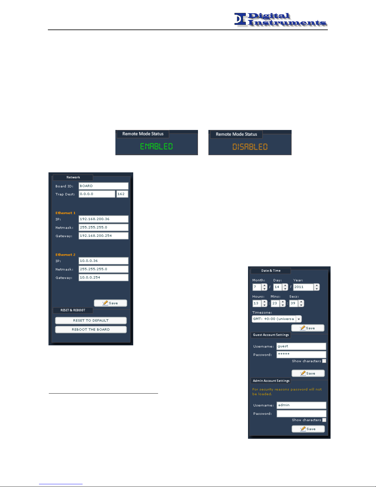
The MXS-EVO is managed by the network using a common browser by simply connecting to the associated IP address.
Mode Menu
Local/Remote
In local mode is only possible to modify operative parameters from the front panel display. In remote
mode it can be done from WEB, SNMP and REMOTE CONTROLS.
In the WEB interface this value is visible in the Remote Mode Status field. When Disabled is shown no
operation can be made to change the operative status of the apparatus.
Please note that the value of this parameter can only be changed by the front panel.
Network Configuration Panel
Board ID
Allows to define a name to the apparatus, useful for identifying it on the network
Trap Dest
Allows to configure the destination server of the traps related to the events.
IP
Allows to set up the IP address associated to the the specific network interface.
To activate the changes, system needs to restart.
Netmask
Allows to set the netmask associated to specific network interface. To activate
the changes, system needs to restart.
Gateway
Allows to set the gateway associated with
specific network interface. To activate the
changes, system needs to restart.
Reset to default
Restores the original configuration
Reboot the board
Restarts the device
Date & Time
Allows to view/set the date and time of the apparatus. Note that this will still be
automatically updated to that received by satellite.
Timezone
Allows to set the UTC offset for proper time visualization.
This setting determines the IRIG-B time offset.
Guest Account Settings
Allows to change the credentials of the user account (see below for more details)
Admin Account Settings
Allows to change the credentials for the administrator account (see below for more
details)
Page 23
MXS-EVO - MANUAL
-------------------------------------------------------------------------------------------------------------------------------------------------------------------------------------------------------------------------------------------------------------------------------------------------
MXS-EVO – Manual – Rev 1.7 - 23 -
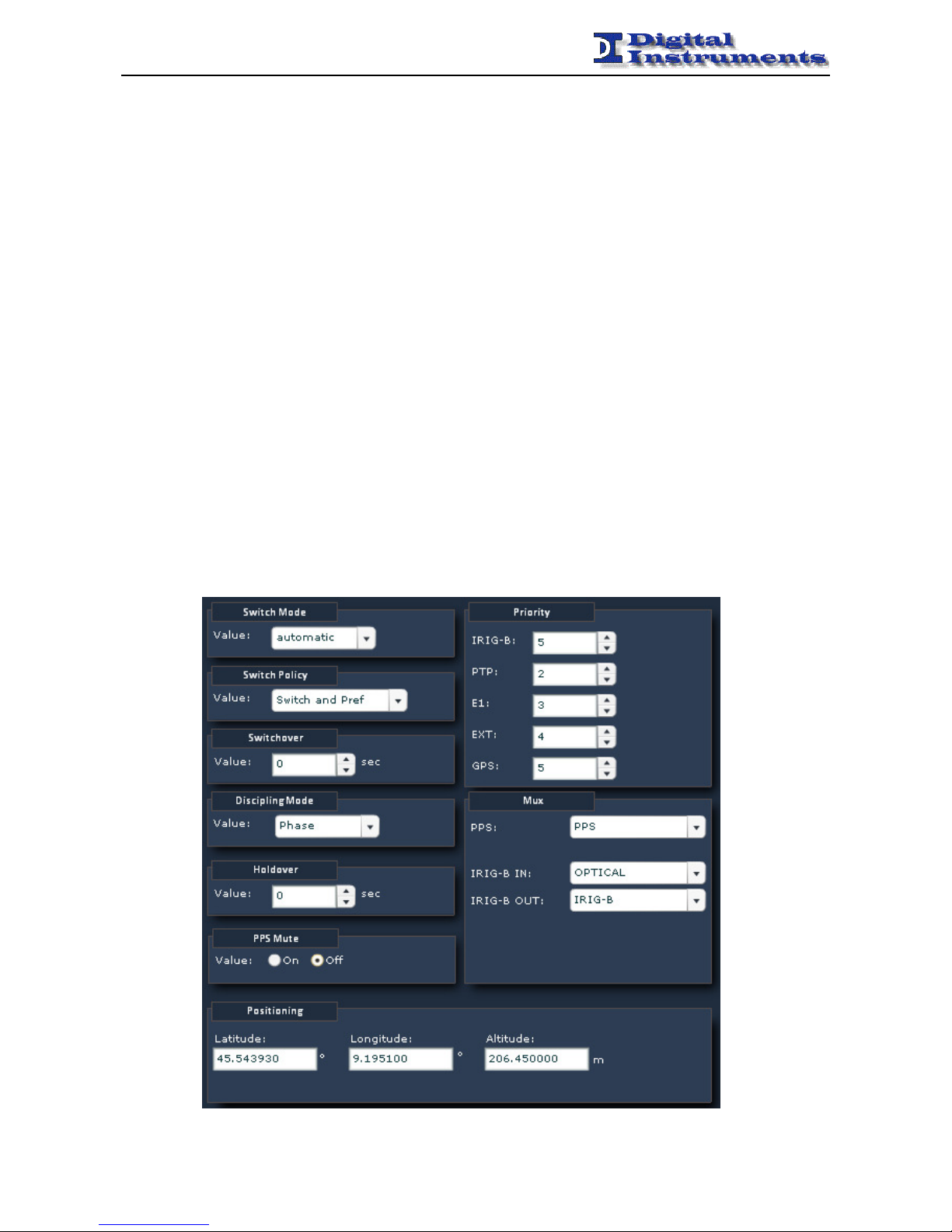
Board Config Panel
Source
Permits to force a switch on a different source when the device is configured in manual switch mode.
To switch from the WEB interface just go the the View tab of the Main Panel and click on a source.
Manual/Auto
Allows to set the type of switching (manual or automatic).
Disciplining Mode
Selects the kind of tuning to use when discipling from da EXT or E1 reference.
The frequency tune is faster, but loses the phase alignment of the PPS provided in output.
Policy
Indica la politica attualmente utilizzata per la commutazione in modalità automatica. Per avere maggiori
Indicates the policy used to do switchovers. Toh ave more details on the subject please consult the relative
section Switchover Policies.
Switchover
Allows to modify the switch-over time. For more details please consult the relative section Switchover.
Priority
Set the priority of each source for the automatic switch (a higher value means a higher priority, 0 disables
the source).
PPS Mute
Inhibits the output of the PPS until the device has reached a synchronized status (tipically a few minutes
are needed).
PPS
Allows to choose which signal to spread on the PPS connectors (default is board PPS).
IRIG-B IN
Permits to choose the source of the IRIG-B input signal (BNC or OPTICAL)
IRIG-B OUT
Allows to choose which signal to spread on the IRIG-B BNC connectors (default is IRIG-B).
Positioning
Permits to change the position of the device (retrieved from GPS if available).
Page 24
MXS-EVO - MANUAL
-------------------------------------------------------------------------------------------------------------------------------------------------------------------------------------------------------------------------------------------------------------------------------------------------
MXS-EVO – Manual – Rev 1.7 - 24 -
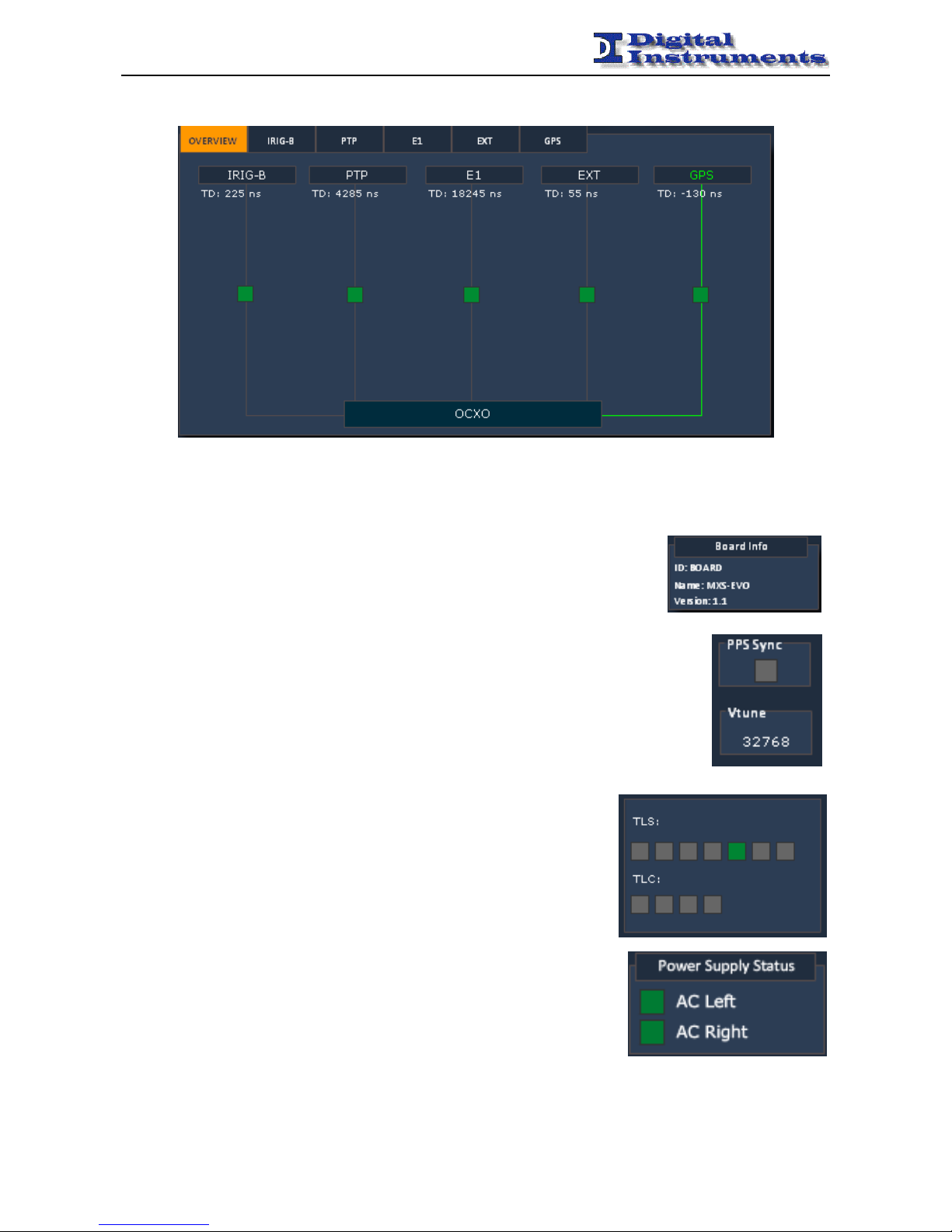
Board Status
Overview
Permits to view the status of all the sources alongside their time reference cvomparison with the internal
reference.
Info
Displays the name of the device and the corresponding software release.
The ID field can be customized by the user to track the device.
These informations are displayed in the Board Info panel of the main page of
the WEB interface.
Disciplining
Shows the current disciplining value given to the internal oscillator and the
synchronization status.
These informations are reported in the PPS Sync and Vtune values on the Main
panel.
TLC
Shows the status of the 4 TLC
0 TLC inactive
1 TLC active
TLS
Shows the status of the 7 TLS
0 TLS inactive
1 TLS active
Supply
Shows the status of the 2 power supplies (left and right).
OFF power supply inactive
ON power supply active
Page 25
MXS-EVO - MANUAL
-------------------------------------------------------------------------------------------------------------------------------------------------------------------------------------------------------------------------------------------------------------------------------------------------
MXS-EVO – Manual – Rev 1.7 - 25 -
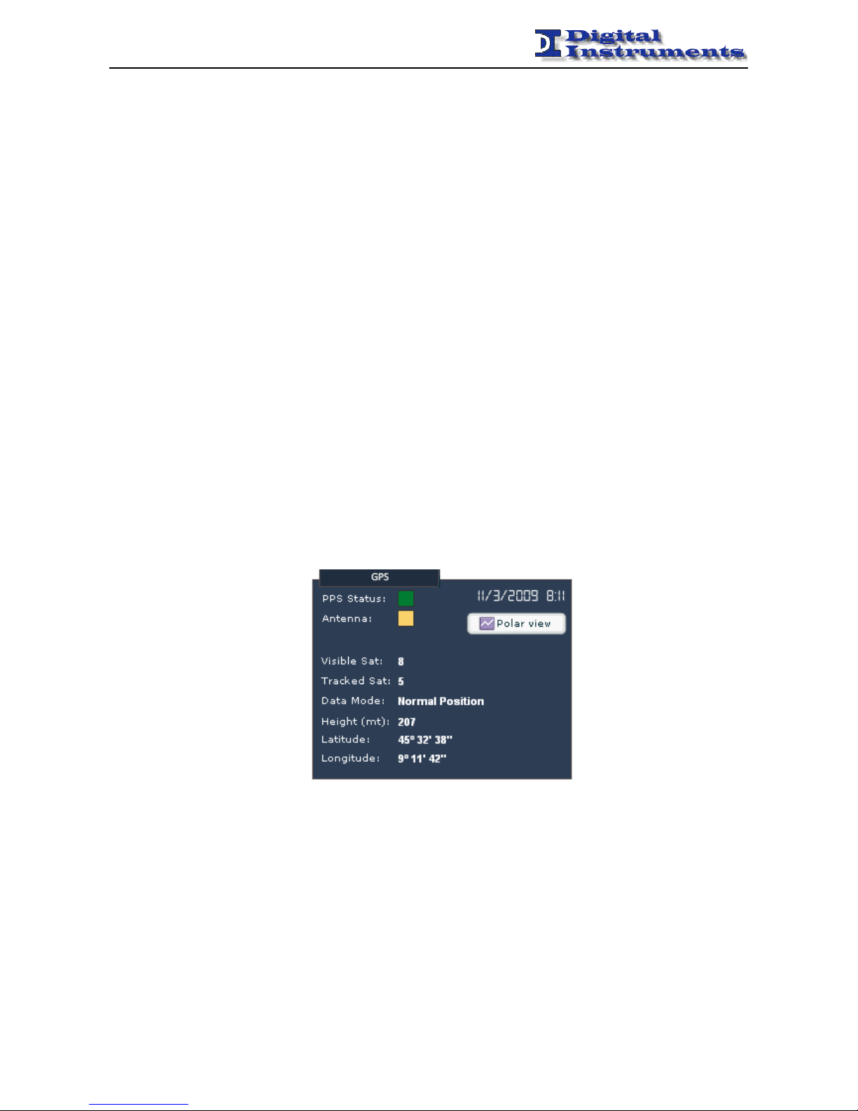
GPS
Status
Displays some informations about the GPS radio.
If present and its time delay in respect to the internal PPS.
Positioning Mode
Permits to set the way in which the GPS module should calculate its geographical position. If extract it
from the information collected from the satellites or using the one given by the user.
The “Altitude Hold” mode may not be available on every GPS module.
Latitude
Permits to view/set the latitude of the GPS antenna.
Longitude
Permits to view/set the longitude of the GPS antenna.
Height
Permits to view/set the height of the GPS antenna.
Cable Delay
Permits to set the length of the antenna cable connected to the GPS module, so to compensate the delays
introduced by the signal propagation
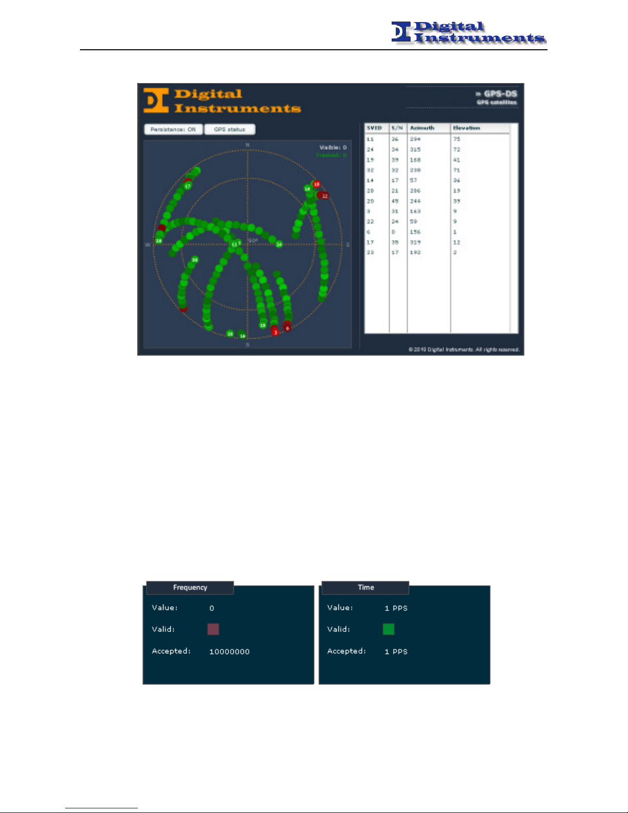
Show Ch Status
Shows the status of the channels of the GPS receiver
The snr, the elevation and the azimuth of the visible satellites are reported
To cycle through the various channels use keys ↓ and ↑.
Show Global Info
Shows some info about the GPS module:
Visibile Sats the number of visible satellites
Tracked Sats the number of tracked satellites
PPS Status the status of the PPS signal
Antenna the status of the antenna
All these variables are reported in the GPS status window. Cable Delay can be set in the GPS Configuration,
whilst Latitude, Longitude and Height cannot be set by WEB, but only from SNMP or front panel.
Page 26
MXS-EVO - MANUAL
-------------------------------------------------------------------------------------------------------------------------------------------------------------------------------------------------------------------------------------------------------------------------------------------------
MXS-EVO – Manual – Rev 1.7 - 26 -
The satellite view can be opened by pressing the Polar view button.
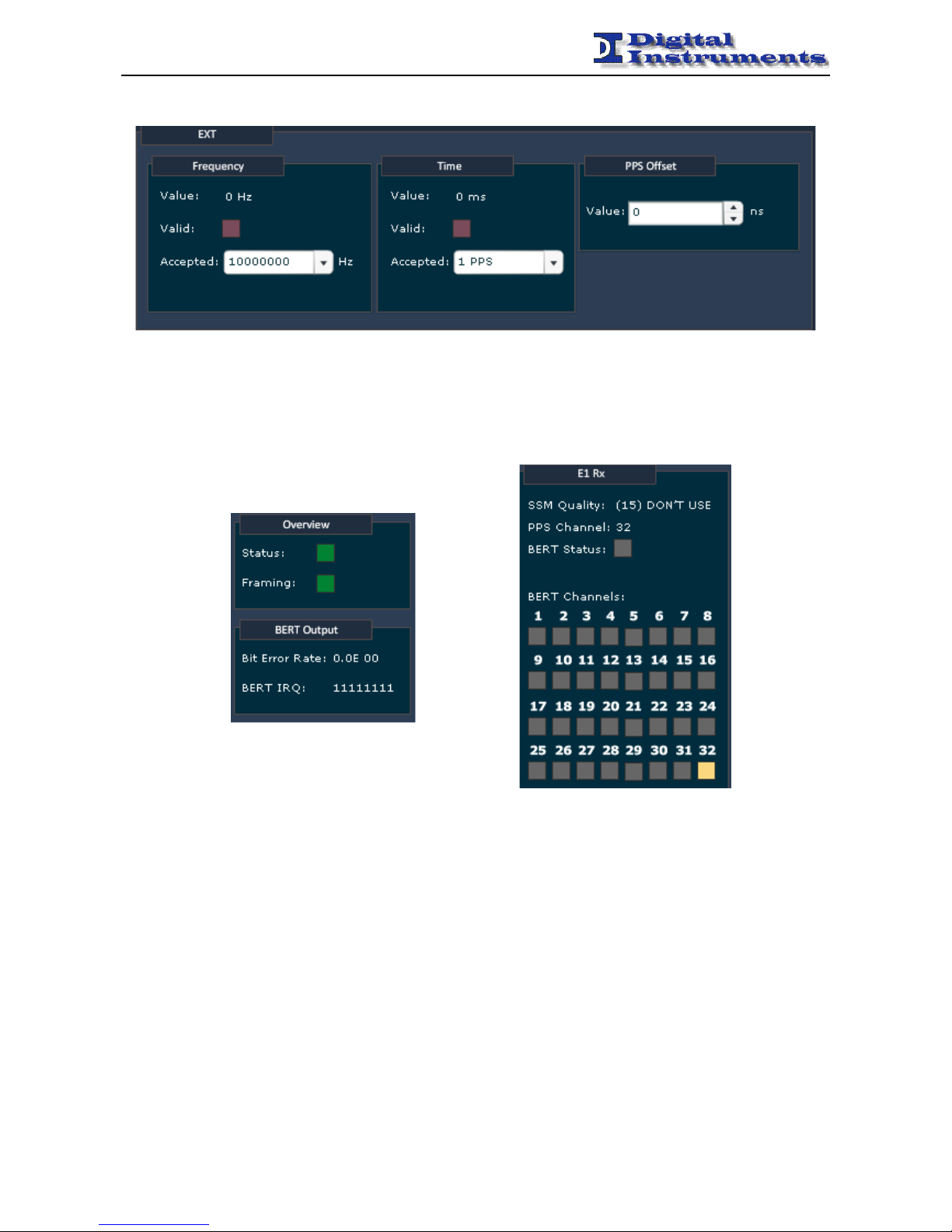
EXT
Frequency Ref.
It allows to display the frequency reference, expressed in Hz, which is currently supplied as an input to the
apparatus and if this value has been accepted. Its acceptance or not depends on the value set as acceptable
and on tolerance (viewable by pressing ↓).
Time Ref.
Allows to display the time reference, expressed in PPS (pulse per second) or in ms, currently supplied as
input if this value has been accepted. Its acceptance or not depends on the value set as acceptable and on
tolerance (viewable by pressing ↓).
It also indicated the time delay (TD) of the external time reference and measured respect to the PPS signal
outputted from the apparatus.
These values are displayed in the EXT tab of Main Panel.
Settings
Allows to set the eligible values for the time and frequency reference between the pre-set.
Page 27
MXS-EVO - MANUAL
-------------------------------------------------------------------------------------------------------------------------------------------------------------------------------------------------------------------------------------------------------------------------------------------------
MXS-EVO – Manual – Rev 1.7 - 27 -
These values are configurable by the GPS / EXT / PTP Config Panel.
E1
For informations concerning the E1 status variables, see paragraph "E1" and specifically subsections "status
information" and "settings available."
In the web interface it’s possible view the values of state variables of the settings in Tab E1 of the Main Panel,
while is possible change the settings on the E1 Config Panel.
Page 28
MXS-EVO - MANUAL
-------------------------------------------------------------------------------------------------------------------------------------------------------------------------------------------------------------------------------------------------------------------------------------------------
MXS-EVO – Manual – Rev 1.7 - 28 -
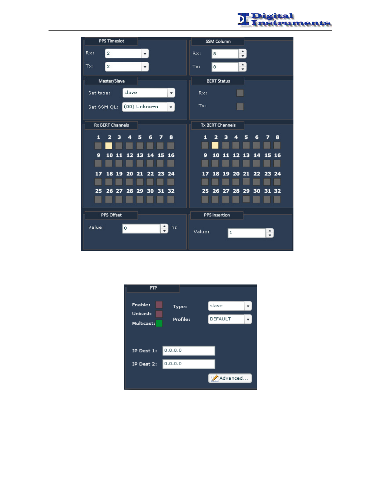
PTP
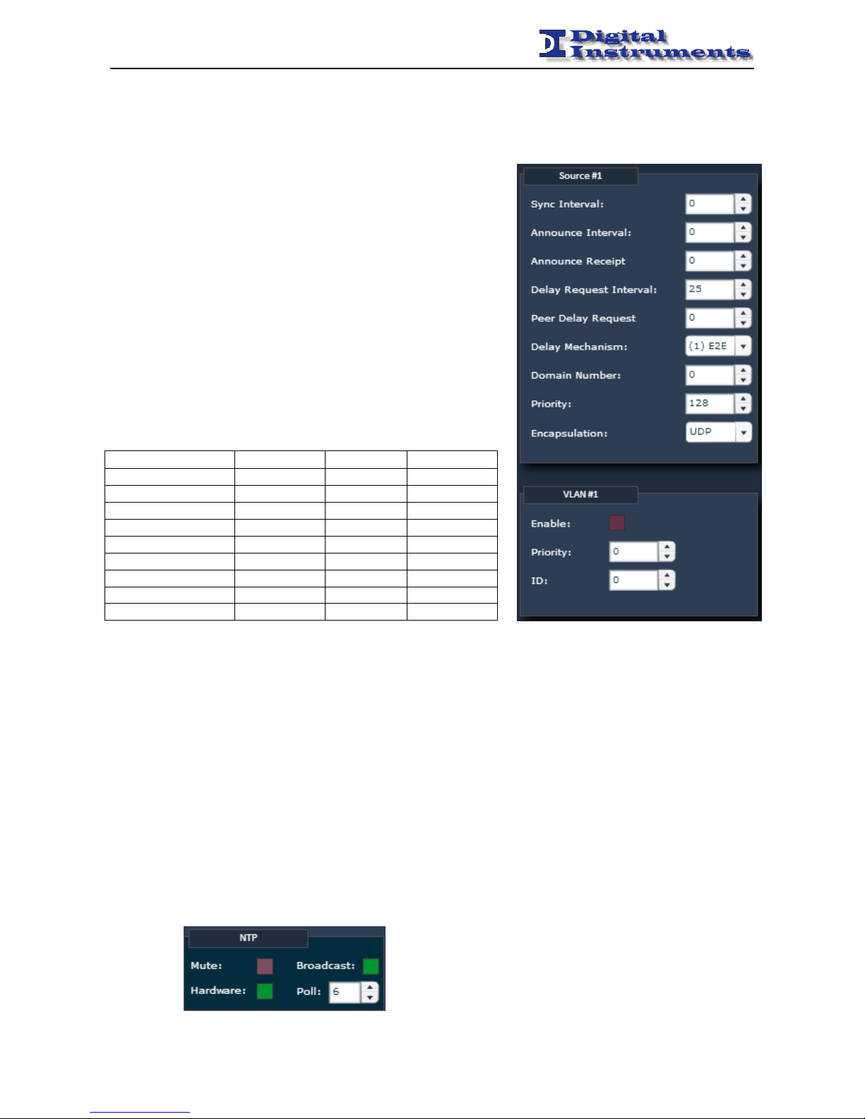
The PTP settings are split across two panels. The in-depth configuration is carried on in the Advanced panel,
whilst the basic settings can be directly changed from the Sources Panel.
Enable
Allows to switch on or off the PTP.
Type
Allows to choose to configure the device as a Grandmaster or a Slave.
Page 29
MXS-EVO - MANUAL
-------------------------------------------------------------------------------------------------------------------------------------------------------------------------------------------------------------------------------------------------------------------------------------------------
MXS-EVO – Manual – Rev 1.7 - 29 -
Profile
Allows to choose to choose between some predefined profiles for common configurations.
Multicast/Unicast
Allow to choose the type of communication mechanism.
IP Dest
Allows to define a series of additional unicast addresses.
Advanced
Allows to configure a set of advanced settings.
Intervals
The various interval values are expressed in power of 2, so 0
corresponds to 1 second, 1 to 2 seconds and -1 to 0.5 seconds.
VLAN
Allow to enable or disable the 802.1Q protocol.
Follows a comparative table of the various profiles. In order to customize
some specific values a CUSTOM profile must be chosen.
DEFAULT TELECOM POWER
Sync
1/s 32/s 1/s
Announce
2s 8/s 1/s
Announce timeout
12s 0.25s 6s
Delay Request
8s 32/s -
Peer Delay Request
- - 1/s
Delay Mechanism
E2E E2E P2P
Domain Number
0 4 0
Encapsulation
UDP UDP Layer2
Routing
MULTICAST UNICAST MULTICAST
IRIG-B
The only two settings related to the IRIG-B block are the input selector (IRIG-B Mux) and the Timezone.
NTP
Mute
Do not reply to any NTP request before synchronization is completed and time reference is valid.
If the time reference is invalid the clock unsynchronized is risen, but some clients may not check the flag and
blindly trust the time value. This setting is for additional safety.
Hardware
Enable NTP hardware timestamping support for improved performance (disables PTP)
Broadcast
Periodically send broadcast NTP server packets (without authentication)
Poll
Specify the interval between broadcast packets
Page 30
MXS-EVO - MANUAL
-------------------------------------------------------------------------------------------------------------------------------------------------------------------------------------------------------------------------------------------------------------------------------------------------
MXS-EVO – Manual – Rev 1.7 - 30 -
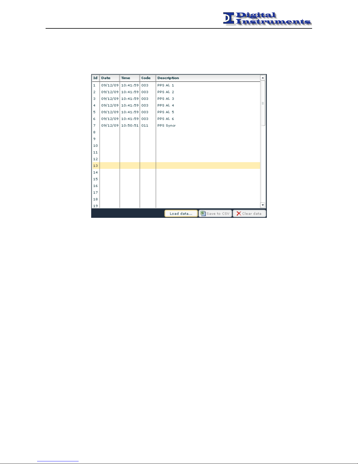
Event Log
On the WEB is available the apparatus log from Event log section.
50 entries are presented.
It is possible to delete the logs and save them in csv. format.
Events related to the board
Event Code 001 Power ON Apparatus on
Event Code 002 Switch Switching on GPS / EXT / E1 source
Event Code 003 PPS alarm Alarm on PPS (1÷4)
Event Code 004 Clock alarm Alarm on 10 MHz (1÷4) signal
Event Code 005 GPS Serial Detection or loss of connectivity of the GPS radio
Event Code 006 Supply Insertion or removal of a power supply (L, R)
Event Code 007 Switch Alarm More than 3 exchanges in less than 5 minutes
Event Code 008 GPS PPS Status change of PPS from satellite
Event Code 009 GPS Antenna GPS antenna connection or disconnection
Event Code 010 Bad Vtune Vtune incorrect value
Event Code 011 PPS Syncr Sychronization completed
Event Code 012 E1 Signal Change in the status of the presence of the E1 signal
Event Code 013 E1 Frame Change in the status of the presence of the E1 framing
Event Code 014 E1 PPS Change in the status of the presence of the E1 PPS
Event Code 015 EXT Freq Change in the status of the presence of the EXT frequency
Event Code 016 EXT Time Change in the status of the presence of the EXT time
Event Code 018 PTP PPS Change in the status of the PPS rebuilt by PTP
Event Code 019 IRIG-B Change in the status of the presence of the IRIG-B signal
Page 31
MXS-EVO - MANUAL
-------------------------------------------------------------------------------------------------------------------------------------------------------------------------------------------------------------------------------------------------------------------------------------------------
MXS-EVO – Manual – Rev 1.7 - 31 -
SNMP Trap Management
For each event related to the board, is generated a trap in parallel parallel to the machine set under TrapDest. The trap
number reflects the event number and the contents of the SNMP variable associated contains the details (for example,
the channel referred to the event).
User Account
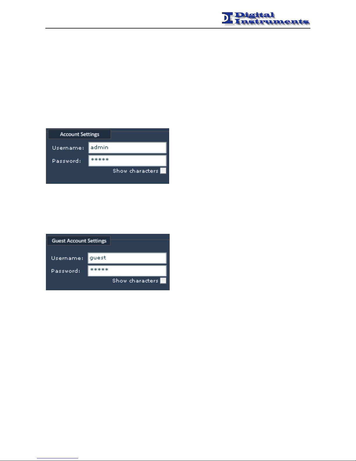
The main user who has access to the apparatus is the administrator. He is able to change its credentials under Account
Settings.
It’s possible set a user account that is able to use the apparatus remotely in read-only mode, without the possibility of
changing its configuration.
The username and password for this guest account can be set by the administrator under Guest Account Settings.
The default credentials are:
admin admin / admin
guest guest / guest
About SNMP:
Read community string public
Write community string public
Page 32
MXS-EVO - MANUAL
-------------------------------------------------------------------------------------------------------------------------------------------------------------------------------------------------------------------------------------------------------------------------------------------------
MXS-EVO – Manual – Rev 1.7 - 32 -
Custom Settings
The device permits to have some ad-hoc customizations through the unlock with particular activation codes.
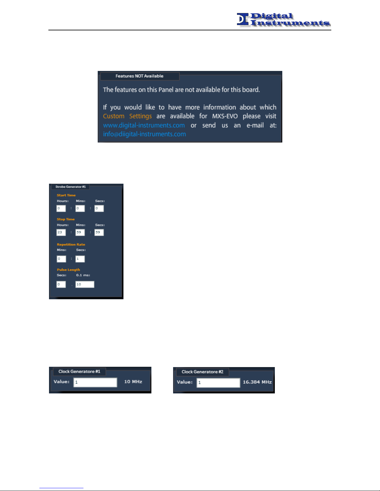
Pulse Generation
The device is able to generate a programmable pulse in place of the IRIG-B DCLS signal (on the BNC connector) or the
PPS signal.
The following parameters can be set:
- <Start Time> HH:MM:SS
- <Stop Time> HH:MM:SS
- <Repetition Rate> MM:SS
- <Pulse Length> SS.ssss
The system generates a sequence of pulses of <Pulse Length> length and repeating
every <Repetition Rate> starting at <Start Time> and stopping at <Stop Time>.
Please note that the <Start Time> is always synchronous to the internal PPS
(eventually disciplined via an external source).
Clock Generation
The device is able to generate two distinct programmable square wave clocks by dividing two different sources with
integer dividers:
• 10 MHz
• 16.384 MHz
Please note that the rising edge of the resulting clock is synchronous to the internal PPS, if the frequency is integer.
Page 33

MXS-EVO - MANUAL
-------------------------------------------------------------------------------------------------------------------------------------------------------------------------------------------------------------------------------------------------------------------------------------------------
MXS-EVO – Manual – Rev 1.7 - 33 -
First Run
First Installation
1. Connect at least one of the possible sources (GPS, EXT, E1, PTP, IRIG-B) in the following way:
• GPS: connect the GPS antenna cable to the proper GPS ANTENNA socket on the rear.
• EXT: connect a frequency or time reference on the proper connector on the rear.
• E1: connect an E1 connector on the proper input socket on the back.
• PTP: connect an ethernet cable to the ethernet port on the back (network should be IEEE 1588 compliant
for best performance)
• IRIG-B: connect a coax or optical connector on the proper sockects on the back (and select the proper
input in the IRIG-B Mux selection)
2. Connect the MXS-EVO to the power grid.
After a few seconds the LCD display should light up (without an ethernet cable it would take a little more) and the leds
under the keyboard should start blinking.
Checkup
When booted the device starts forcing the following configuration:
• Remote mode selected
Follows this simple procedure to verify the correct behaviour of the apparatus:
• Connected sources are being correctly recognized
o Navigate to GPS Status and check that the GPS radio is being recognized
Go to GPS Show Global Info and check the status of the Antenna entry
o Navigate to EXT Frequency Ref. and check that the frequency source is valid. Eventually modify
the accepted frequency under EXT Settings
o Navigate to EXT Time Ref. and check that the time source is valid.
o Navigate to E1 Status and check that the E1 signal and E1 framing are both valid.
o If the PTP protocol is needed check if it is enabled under PTPEnabled
o Check the status of the PTP signal by navigating to PTP Status and verifying that SLAVE is
reported
o Check the status of the IRIG-B signal by navigating to IRIG-B Status and verifying that the signal
is present and the date is valid
• It is possible to immediately check the status of the various sources by looking at the leds on the front panel.
Local/remote mode
The device can be used in two different modes:
1. Local
It is possible to change the device settings only from the front panel
Info are visible in read-only mode from WEB, SNMP or via TLS
2. Remote
Info are visible in read-only mode from the front panel
It is possible to change device settings from WEB, SNMP or TLC
To change mode operate the Mode MenuLocal/Remote setting from the front panel.
Network configuration
To configure the network is possible to operate via the front panel under the Network menu. A reboot is required for the
changes to take effect.
After having got a valid IP address it is possible to connect with the device via WEB by using a common browser at the
address http://<board_ip>
Page 34

MXS-EVO - MANUAL
-------------------------------------------------------------------------------------------------------------------------------------------------------------------------------------------------------------------------------------------------------------------------------------------------
MXS-EVO – Manual – Rev 1.7 - 34 -
The default credentials are:
administrator (read and write) admin / admin
guest (read only) guest / guest
From here, it’s possible to check:
• Presence of the GPS antenna
In the GPS tab of the Main Panel the Antenna led should be green and, after a few minutes from the boot, the
PPS Status led should become green, too.
• Presence of the Ext. Frequency signal
In the Ext tab of the Main Panel the Valid led of the Frequency box should be green. If not do eventually
modify the expected frequency in the GPS/EXT Config Panel.
• Presence of the Ext. Timing signal
In the Ext tab of the Main Panel the Valid led of the Time box should be green.
• Presence of the E1 signal
In the E1 tab of the Main Panel the Signal and Framing leds should be green.
• Presence of the PTP signal
In the PTP tab of the Main Panel the Enabled led should be green and Status should display Slave.
• Presence of the IRIG-B signal
In the IRIG-B tab of the Main Panel the Present led should be green and Date should display a valid date.
Automatich switchover
In order to enable the automatic switchover is better to first check a few settings:
• Switchover policies
It is possible to set different policies for the switch.
These policies can be set from the front panel (Board SettingsPolicy), from SNMP (policy) or from WEB in
the Board Configuration page.
• Switchover treshold
It is possible to set a treshold to wait before switching to another source.
These policies can be set from the front panel (Board SettingsSwitchover), from SNMP (switchover) or from
WEB in the Board Configuration page.
• Disciplining mode
It is possible to specify if the disciplining from the external frequency or from E1 has to be done in frequency
or phase.
• Automatic switchover
To finally enable the automatic switchover is possible to operate from the front panel (Board
SettingsManual/Auto), from SNMP (switchMode) or from WEB in the Board Configuratio page.
Page 35
MXS-EVO - MANUAL
-------------------------------------------------------------------------------------------------------------------------------------------------------------------------------------------------------------------------------------------------------------------------------------------------
MXS-EVO – Manual – Rev 1.7 - 35 -
Appendix A: Quality Factor
General Review
This appendix is intended to illustrate the meaning and motivation of the introduction of the Quality Factor within the
Digital Instruments equipments.
Although the installation of a GPS device is relatively easy, it can hide certain issues that in some cases it can affect the
proper functioning.
It is therefore expected to monitoring certain operating parameters so as to make immediate validation of a Circuit or
finding the source of any problems.
GPS antenna positioning
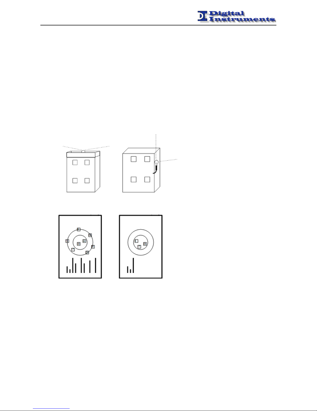
GPS antenna should be positioned on a tower or on a roof with a good view of the GPS satellite constellation.
GOOD BAD
POSITIONING POSITIONING
If not, the algorithm of regulation may not behave optimally and short term stability of the PPS and 10 MHz references
it could be invalidated.
It’s possible to evaluate the goodness of the positioning of the antenna in some ways:
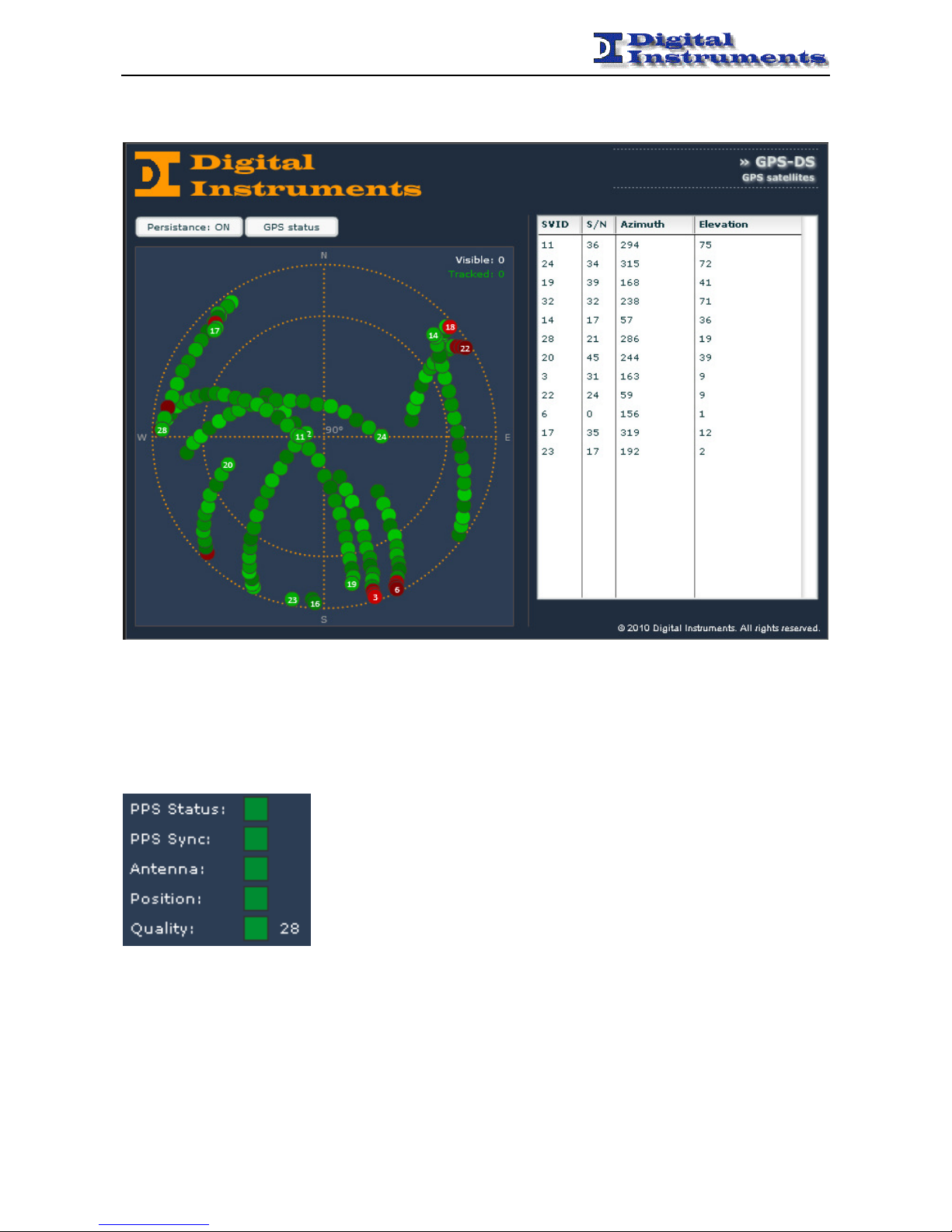
1. checking the power of received signal from each satellite from the Polar Plot
2. checking and verifying that the Quality Factor is acceptable (typically> 25)
3. checking that the PPS generated by the radio (PPS Status) is valid (green LED)
Se così non fosse l’algoritmo di disciplinamento potrebbe non comportarsi in maniera ottimale e la short term stability
dei riferimenti PPS e 10 MHz ne potrebbe venire inficiata.
Page 36
MXS-EVO - MANUAL
-------------------------------------------------------------------------------------------------------------------------------------------------------------------------------------------------------------------------------------------------------------------------------------------------
MXS-EVO – Manual – Rev 1.7 - 36 -
It’s possible get an idea of potential obstacles that limit the visibility of the GPS constellation to the radio observing the
polar graph of satellites after a few hours of persistence.
Quality Factor
Quality Factor is the operating parameter that indicates the quality of the GPS signal received by the antenna. It is
considered an acceptable value if > 25. If the Q.F. is lower, it is possible that there are problems with the GPS signal
reception and this involves a greater number of holdover and therefore a less precise synchronization.
The value of the Quality Factor is shown in GPS tab of Main Panel Page.
Page 37
MXS-EVO - MANUAL
-------------------------------------------------------------------------------------------------------------------------------------------------------------------------------------------------------------------------------------------------------------------------------------------------
MXS-EVO – Manual – Rev 1.7 - 37 -
Statistics
The device stores some useful statistical informations to evaluate the proper functioning over time:
Holdover Num shows the number of times that the GPS radio has entered into holdover mode in response to
a problem (under optimal conditions should be low)
Holdover Max shows the duration of the longer hold-over (under optimal conditions should be low)
Quality Min indicates the smallest GPS antenna quality factor recorded (under optimal conditions should
be high)
PPS Dist Max indicates the maximum distance affected by the PPS generated by the GPS radio (under
optimal conditions should be low)
Pos Alarm Num indicates the number of times that there was a wrong geo-positioning under optimal
conditions should be low)
It's a good idea to reset the stats before a capture session, because some values may be spurious in the first
phase of synchronization or acquisition of satellites by the GPS radio.
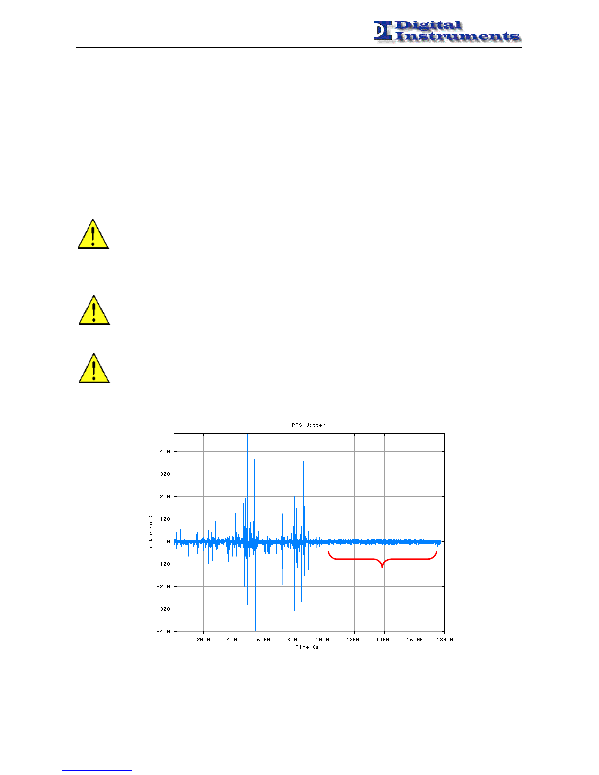
Automatic Site Survey
In certain situations it may be convenient activate the Positioning Mode of GPS radio in Automatic Site
Survey. In this mode the radio privileges the accuracy of temporal information at the expense of that position
(as long as the antenna is not moved), so as to preserve signal integrity PPS in limited visibility conditions or
in the GPS constellation or in presence of potential sources of interference.
If there are problems or abnormalities during the first installation or after moving the unit in a distant
geographic location, GPS radio can be resetted by deleting the almanac and positioning information that is
saved by the appropriate entry in the GPS menu. Should be also necessary to reset the device in Automatic
Site Survey mode, since the radio, after completing the survey - which takes about 3 hours - automatically
returns to Position Hold mode.
POSITION HOLD
Page 38
MXS-EVO - MANUAL
-------------------------------------------------------------------------------------------------------------------------------------------------------------------------------------------------------------------------------------------------------------------------------------------------
MXS-EVO – Manual – Rev 1.7 - 38 -
Appendix B: FAQ
D: How is it possible to certify the various time references?
R: In order to certify a particular reference is better to have the device disciplined by GPS or from another stable
source.
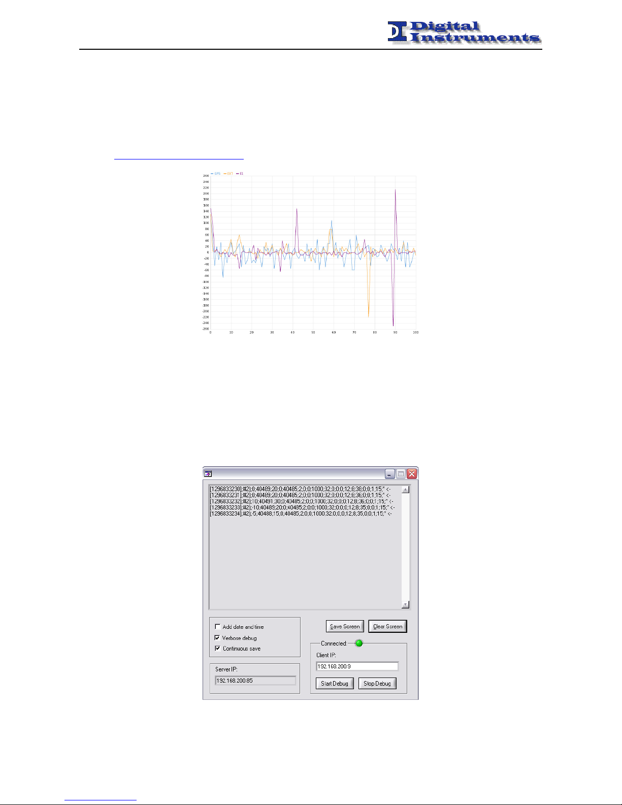
In this way is possible to evaluate the jitter of the reconstructed PPS in different ways:
1. by asking the device the log of the last 6 hours
http://x.x.x.x/cgi-bin/savestability
2. by letting an external event logger collect the data (e.g. AON Console Manager)
3. by using a debug utility to retrieve the live values (distance, jitter, validity) and by post-processing them.
ftp://digiguest:[email protected]/Server%20TCP%20v2.zip
To do so is simply necessary to launch the utility and specify the correct IP address of the device.
Is better to configure the utility with the following settings.
Add date an time OFF
Verbose debug ON
Continuous save ON
Page 39

MXS-EVO - MANUAL
-------------------------------------------------------------------------------------------------------------------------------------------------------------------------------------------------------------------------------------------------------------------------------------------------
MXS-EVO – Manual – Rev 1.7 - 39 -
Press the Save Screen button and specify a file on which to save the data. The acquisition is now started and ends when
the utility is closed. If the Continuous save field is not enabled is possible to press Save Screen in order to save the data
currently acquired (it may slow down the PC if there is much data to save).
The resulting file is a simple csv that may be edited and viewed by a commond spreadsheet program (e.g. Microsoft
Excel).
Follows the complete list of all the values that are exported:
Time number of seconds since epoch (1st January 1970)
SRC num number of reference (1 GPS, 2 EXT, 3 E1, 4 PTP, 5 IRIG-B)
PPS jitter (ns) short-term stability of the source PPS
Vtune corrente current vtune value of the OCXO
PPS distance (ns) distance of the source PPS against the reference PPS
holdover num (s) number of seconds from which the device is not disciplining
Vtune stabile last stable vtune
Sync num number of PPS resyncs
Antenna status antenna status (0 OK)
T-RAIM solution PPS status (0 OK)
T-RAIM alarm (ns) maximum distance of the reconstructed PPS in order to be considered valid
T-RAIM error (ns) GPS PPS accuracy
GPS error GPS PPS error
Visible sats number of visible satellites
Tracked sats number of tracked satellites
Quality factor quality factor (based on the GPS antenna, > 25 OK)
need_pps_reset (internal use)
need_pwm_duty_stable (internal use)
pps_polarization (internal use)
pwm_speed_limit (internal use)
Sync done * locked
Master <- currently selected source
Is suggested to:
1. Collect the data as previously explained in .csv format (using Continuous save option)
2. open Excel and apply an automatic filter on the 2nd column (the one of the source number with the #)
3. initially filter based on source #1 (GPS) and verify that the 5th column (PPS distance) would contain values
near 100 ns (the base unit is the ns)
4. subsequently filter based on the other sources #2 (EXT), #3 (E1), #4 (PTP) o #5 (IRIG-B) and plot the 5th
column (it shows the precision of the reconstructed PPS).
D: Is it possible to reach NTP stability below 1 ms?
R: Yes. In order to achieve sub-ms precision it is necessary to enable the NTP hardware timestamping support. In this
way is possible to have timestamps accurate to better than 100 ns.
Please note that the client device should be able to cope with the interleaved mode (please refere to NTP section for
further details).
In Windows Vista and Seven a few additional steps may be required to improve the performance:
• Disable CPU spread spectrum capabilities in the BIOS
• Disable CPU frequency scaling capabilities
• Set the following environmental variable:
NTPD_USE_INTERP_DANGEROUS=1
If nothing works you it may also possible to try with the serial port. The device outputs a NMEA stream @ 9600 bps
8/N/1 and triggers the PPS on pin 1 (DCD)
The following configuration may be used in ntpd.conf:
server 127.127.20.1 minpoll 4 maxpoll 4 mode 24 # NMEA @ 9600 bps, $GPZDA
fudge 127.127.20.1 time2 0.0110185 # time correction
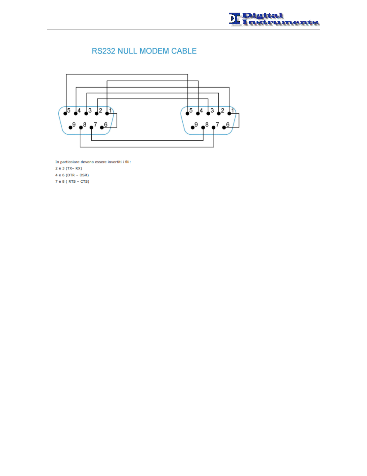
A NULL modem cable should be used to connect with the device on the serial port.
Page 40
MXS-EVO - MANUAL
-------------------------------------------------------------------------------------------------------------------------------------------------------------------------------------------------------------------------------------------------------------------------------------------------
MXS-EVO – Manual – Rev 1.7 - 40 -
The schematic is depicted here:
Page 41

MXS-EVO - MANUAL
-------------------------------------------------------------------------------------------------------------------------------------------------------------------------------------------------------------------------------------------------------------------------------------------------
MXS-EVO – Manual – Rev 1.7 - 41 -
Appendix C: Changelog
Release 1.0 (december 2011)
• First release
Release 1.1 (february 2012)
• Added support for IRIG-B
Release 1.2 (march 2012)
• Added support for Synchronous Ethernet
Release 1.3 (april 2012)
• Enhanced disciplining of the NTP server
Release 1.4 (june 2012)
• Enhanced recognition of the external frequency
• Added support for hardware upgrade
Release 1.5 (august 2012)
• NTP server even without GPS
• Auto-recognition of the IRIG-B input
• IRIG-B robustness increased
Release 1.6 (september 2012)
• SyncE management simplified
Release 1.7 (october 2012)
• Added clock generation support
Release 1.8 (october 2012)
• Added handling of the ESMC packets for the SyncE
Release 1.9 (november 2012)
• Added timing information over E1
Release 2.0 (january 2013)
• Added PTP custom parameters
• Added disciplining parameters in the PTP Announce Message
• Added support for PTPv2 unicast through signalling messages
Release 2.1 (january 2013)
• Added support for PTP over Layer 2 and VLAN (802.1Q)
Release 2.2 (january 2013)
• Software libraries updated
Release 2.3 (february 2013)
• Resync of the PPS when disciplining in frequency only when necessary
Release 2.4 (march 2013)
• Added support for NMEA GPS radio
Release 2.5 (april 2013)
• Updated GUI to fix some problems in the E1 panel
Release 2.6 (august 2013)
• Updated PTP settings
Page 42

MXS-EVO - MANUAL
-------------------------------------------------------------------------------------------------------------------------------------------------------------------------------------------------------------------------------------------------------------------------------------------------
MXS-EVO – Manual – Rev 1.7 - 42 -
Release 2.7 (september 2013)
•
Added multiple VLAN support
Release 2.8 (october 2013)
•
Added support for NTP hardware timestamping
Release 2.9 (october 2013)
•
Added support for PPS over serial line
Page 43

MXS-EVO - MANUAL
-------------------------------------------------------------------------------------------------------------------------------------------------------------------------------------------------------------------------------------------------------------------------------------------------
MXS-EVO – Manual – Rev 1.7 - 43 -
Assistance
For support requests please download the form from the website:
http://www.digital-instruments.it/ita/assistenza.php
Compile it in its entirety by specifying as precisely as possible and giving as many details as possible about the type of
fault detected.
You can then send the form to [email protected], via fax to +39.02.66506103, or enter it directly
into the box when sending goods for repair.
You can also contact us at +39.02.66506250 Monday to Friday from 9 to 13 and from 14 to 17 (GMT+1 Time).
Page 44

MXS-EVO - MANUAL
-------------------------------------------------------------------------------------------------------------------------------------------------------------------------------------------------------------------------------------------------------------------------------------------------
MXS-EVO – Manual – Rev 1.7 - 44 -
Technical Data
Programmable outpts
Outputs 12
Signals PPS, IRIG-B DCLS, IRIG-B AM, E1, 2.048 MHz, 10 MHz
Output impedance 50 Ω
Output connector BNC
Frequency Reference
Signal 10 MHz sine wave, 2.048 MHz sine wave
Spectral Purity -70 dBc (harmonic)
-75 dBc (non-harmonic)
Phase noise -130 dBc at 1kHz
Output level 13 dBm
Output impedance 50 Ω
Output connector BNC
Stability 1e-12 daily average (OCXO locked to GPS on SA)
1e-10 daily average (OCXO free run)
Time Reference
Signal 1 PPS, 100µs Duty, Rising Edge
Output level TTL 5 Vpp, Square wave
Output impedance 50 Ω
Output connector BNC
GPS Section
Receiver 12 Channels L1 1575.42 MHz
Tracking Correlation on 12 satellites
PPS accuracy < 50 ns on SA
Antenna connector TNC
Collection time < 4 min
External Section
Frequency Reference
Standard frequencies 1MHz, 2MHz, 2.048MHz, 5 MHZ, 10 MHz
Input level From -2 dBm to 16 dBm, sine wave
Time Reference
Standard periods 1 PPS
Input level TTL 5 Vpp, square wave
Input impedance 50 Ω
Input connector BNC
E1 Section
Standard signal E1 256S multiframe (16 frame for each multi frame) CRC-4
Input/Output impedance 75 Ω
Input/Output connector BNC
PTP Section
Protocol IEEE 1588-2008 (PTPv2)
Role Grandmaster clock source (GPS) or slave
Time stamping Hardware
Precision < 1 µs
NTP Section
Protocol NTP version 4
Role Grandmaster clock source (GPS)
Stratum 1
Precision < 10 ms with software timestamping
Page 45

MXS-EVO - MANUAL
-------------------------------------------------------------------------------------------------------------------------------------------------------------------------------------------------------------------------------------------------------------------------------------------------
MXS-EVO – Manual – Rev 1.7 - 45 -
< 100 ns with hardware timestamping (disables PTP)
IRIG Section
Format B
Modulation Pulse width modulated / Amplitude modulated
Frequency DC / 1 KHz
Information sent TOY (BCD), Year (BCD)
Connector BNC (electrical) or ST (optical 850 nm multimodal)
Signaling
Network connection N° 1 Ethernet 10/100 interfaces, TCP/IP protocol
Signaling N° 7 led on front panel
Serial Connection RS-232 connector DB9 Male +/- 15 kV (ESD)
Remote signalling 7 Dry contact on Weidmuller connector with 3.5 mm step
Remote controllers 4 Dry contact on Weidmuller connector with 3.5 mm step
Supply
Input N° 2 independent supply
Network 95 Vac < > 240 Vac Plug IEC320 integrated, filter EMI/RFI
Sizes
Width 1 Unit 19’’
Depth 300 mm without connectors
Weight 1.5 Kg
Accessories
1 x GPS Antenna
1 x 30 m Belden PRG 7 Cable
2 m Cordon for network supply
Handbook in English/Italian
 Loading...