

Digital Information Preproofer 940, Preproofer 980, Preproofer 780, Preproofer 740 Installation Manual

Preproofer
740/780/940/980
A
capulco Version
Installation manual

Digital Information Ltd.
Technoparkstrasse 1
CH-8005 Zürich
© Copyright by Digital Information Ltd. 2006
This manual is proprietry in nature and the sole property of Digital
Information. It may not be reproduced, in whole or in part, without
the express written permission of Digital Information. Digital
Information reserves the right to modify and/or delete any material
and/or capabilities described herein.
All the documentation in this manual is instructional and for the
operation of Preproofer machine. Digital Information shall not be
responsible for any damage or claims resulting from any errors or
omissions in this manual.
Owning to our policy of continous product development,
specifications, terms and description of Preproofer 940/980 are
subject to change without prior notice.
.
Identifier Hardware Installation manual - EN
Target group Installation, Technician
Product Preproofer Acapulco 740/780/940/980
Versi on V1.30
Article code Preproofer IM7498-012 EN

Table of contents
Preproofer – HW Installation manual I
.
Table of contents
1 Introduction ............................................................................................................... 1-1
2 Safety ...................................................................................................................... 2-1
2.1 Warning............................................................................................................................................ 2-1
3 Tools and Materials required for the Installation.................................................................... 3-2
3.1 Tools required fort he Installation ...................................................................................................... 3-2
3.2 Materials required for the Installation ................................................................................................ 3-2
3.3 Unpacking the Boxes ....................................................................................................................... 3-2
4 Assemble the System.................................................................................................... 4-1
4.1 Overview .......................................................................................................................................... 4-1
4.2 Installation Steps .............................................................................................................................. 4-3
5 Function test .............................................................................................................. 5-1


Introduction
Warning
1
Preproofer – HW Installation manual 1-1
.
1 Introduction
The Preproofer 940/980 is a fully automatic system printing double-sided proofs in 8up format. The system is
based on two Epson Stylus 9400/9800 printing engines, enabling print widths of 111cm (44”).
The Preproofer 740/780 is a fully automatic system printing double-sided proofs in 4up format. The system is
based on two Epson Stylus 7400/7800 printing engines, enabling print widths of 61cm (24”).
Please note:
Installation of this equipment must be done by a trained technician.
Do NOT leave Epson Printers on the stand without securing them with the Printer locking devices.


Safety
Warning
2
Preproofer – HW Installation manual 2-1
.
2 Safety
This section provides important safety information and must be read before switching on or operating
the equipment.
2.1 Warning
All precautions mentioned in this document must be strictly observed at all times. Personnel MUST therefore
read the contents of the document BEFORE commencing any work on the equipment described in the
document.
Improper use of controls and switches, failure to comply with warnings, and the performance of adjustments or
procedures not specified in this document may expose personnel to danger.
Installation of this equipment must be done by a trained technician.
Do NOT leave Epson Printers on the stand without securing them with the Printer locking devices.

3
Tools and Materials required for the Installation
Tools required fort he Installation
3-2 Preproofer – HW Installation manual
.
3 Tools and Materials required for the Installation
3.1 Tools required fort he Installation
• Standard Screwdriver set
• Allen keys set
• Set of spanners 10-15 mm
• Phillips Screw driver set
• Measurement Tape
• Cordless drill to unpack the boxes
• wrench
3.2 Materials required for the Installation
• Local Power cord (not supplied)
• Ethernet cable to connect the ShuffleBox the PC (not supplied)
3.3 Unpacking the Boxes
Make sure the following parts are available, after unpacking the cases:
Large case:
• 2 side Legs
• 2 Shelves
• 2 or 3 Cross beams
• 2 side media guides for roll media
• Power supply with international plug
• Software package with hardware dongle
• Bag if screws, rectangular End plugs, circular end plugs, Printer locking devices
Small case:
• Curver
• 1 anti-curling device + rod
• Upper media deflector
• ShuffleBox + Control panel wires + Y-motor wires
2 Step ladder
All packaged items must be inspected at the customer's site before unpacking begins. The following steps are
taken when there has been damage:
1.) Record the observations on the delivery documentation.
2.) Inform the carrier, shipping agent and insurance agent.
Units may be removed from their box only by an approved engineer or representative. Do not proceed with
unpacking when there has been a damage report until authorized by the shipping and insurance agents.
Assemble the System
Overview
4
Preproofer – HW Installation manual 4-1
.
4 Assemble the System
Assemble the stand as described below. If the stand
comes pre-mounted, please skip this section.
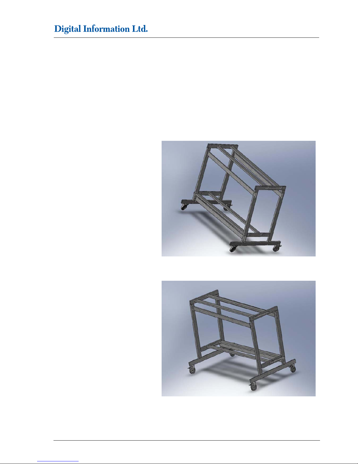
4.1 Overview
Once assembled, the stand should look as:
Front View
Back View

4
Assemble the System
Overview
4-2 Preproofer – HW Installation manual
.
T
he parts positions as shown below:
20x M8 Bolts, 20x M8 washers, 20x M8 Nuts
3 Cross Beams, 2 shelves, 2 side legs

Assemble the System
Installation Steps
4
Preproofer – HW Installation manual 4-3
.
4.2 Installation Steps
1.)
Start building the stand from the bottom upwards.
Insert the wheel beam flanges into the bottom of side
frame. Screw with 2 bolts and washers. This will be
left side. Repeat the same for the right side.
2.) Secure the 3 cross beams. Each beam is secured
by 2 bolts, washers and nuts on each side. Do not
tighten the nuts yet!.
3.) Secure the other complete side as in step 2.
Do not tighten the nuts yet.

4
Assemble the System
Installation Steps
4-4 Preproofer – HW Installation manual
.
4.) Insert the upper shelf and tighten it with 2 screws,
washers and nuts on each side.
5.) Insert the lower shelf and tighten it with 2 screws,
washers and nuts on each side
6.) Glue the lower cable channel underneath the
bottom shelf.
(1) Cable Channel
(2) Hole for Power Supply Shuffle Box, Ethernet
cable
(3) Hole for USB Cable
(4) Open end for mains cable
7.) Glue the upper cable channel underneath the
bottom of the top shelf.
(1) Hole for mains cable
(2) Open end for USB Cable

Assemble the System
Installation Steps
4
Preproofer – HW Installation manual 4-5
.
8.)
Glue the Vertical cable channel behind the side legs.
(1) Vertical cable channel
9.)
On each Epson printer, remove the plastic media
deflectors (3 or 5 on each printer) by opening the front
cover and unscrewing 2 screws on each deflector.
(1) Front Cover
(2) Plastic media deflector
10.)
On the Top printer remove the right side roll holder by
removing 3 screws and the left side roll holder by
removing 2 screws. Remove the plastic cover.
Reassemble again both the right side roll holder and
left side roll holder.
(1) Right side roll holder: remove 3 screws
1
1
1
1
1

4
Assemble the System
Installation Steps
4-6 Preproofer – HW Installation manual
.
(2) Left side roll holder: remove 2 screws
11.)
In the Top printer, remove 3 or 5 screws holding the
back cover.
(1) Remove screws
(2) Back Cover
1
1
1
1
1

Assemble the System
Installation Steps
4
Preproofer – HW Installation manual 4-7
.
12.)
In each location of screws removed, insert round
plastic washer and screw with new elongated screws.
Do not tighten screws.
( 1) Plastic washer with new screw
13.)
Insert the Anti-curling device tighten it with new
screws.
(1) Anti-curling device
1
1
1
1

4
Assemble the System
Installation Steps
4-8 Preproofer – HW Installation manual
.
Check the position of the AntiCurling device. When
the bar is in the lowest position, it should not touch
the blue paper roll side holders.
14.)
Insert the 6” media side guides onto the roll media
spindle. Load the roll media paper edge coming
under the spindle and towards you.
(VERY IMPORTANT!)
(1) 6” side guides
1
1

Assemble the System
Installation Steps
4
Preproofer – HW Installation manual 4-9
.
15.)
Position the Bottom Epson Printer on the bottom
shelf with the threaded hole underneath the printer
aligned over the shelf hole. Take the printer locking
device (large plastic spaced, thin plastic washer and
long screw). Insert the plastic spacer in between the
printer and the shelf and align it in centre to the shelf
hole and the printer hole. Insert the long screw into
the thin plastic washer and screw it from underneath
the shelf.
(1) Large plastic washer
(2) Thin plastic washer
Caution:
Do not leave the printer on the stand without
securing it with the printer locking device!
16.)
Position the Top Epson Printer on the top shelf with
the threaded hole underneath the printer aligned over
the shelf hole. Take the printer locking device (large
plastic spaced, thin plastic washer and long screw).
Insert the plastic spacer in between the printer and
the shelf and align it in centre to the shelf hole and the
printer hole. Insert the long screw into the thin plastic
washer and screw it from underneath the shelf.
Caution:
Do not leave the printer on the stand without
securing it with the printer locking device!
(1) Top Printer
(2) Bottom Printer
1
1
1
1

4
Assemble the System
Installation Steps
4-10 Preproofer – HW Installation manual
.
17.)
Load the paper media through the anti-curling bar.
Feed paper through the metal rod and around the
metal plate and into the epson printer slot.
(1) Metal rod
(2) Metal plate
18.)
Unsnap the black plastic guides inside BOTH the
Epson machines (5 or 7 pieces in each machine).
(1) Plastic Guide
19.)
In the lower printer, remove the 2 of 5 screws (second
screw from the left and second screw from the right)
in the lower row of screws. This lower row of screws
hold the cover plate for the electronics compartment.
Screw 2 protruding screws in each hole and tighten
them with the attached nut.
(1) Remove 2 Top screws
1
1
1
1
1

Assemble the System
Installation Steps
4
Preproofer – HW Installation manual 4-11
.
20.)
Insert the curver in between the upper printer and the
upper cross beam until the bottom plate holes of the
curver rest on the 2 protuding screws
(1) Side cover of Curver
21.)
Switch off the bottom printer and remove the Power
cord. Push the panel down at the position of the
arrows.
22.)
Take off the ink cartridge holder.
(1) 2 screws on the top
(2) 1 screw to take off the blue ink lever handle
1
1
1
1

4
Assemble the System
Installation Steps
4-12 Preproofer – HW Installation manual
.
23.)
Take off the grey paper level handle.
(1) 1 screw
24.)
Take off the maintenance tank and remove the plastic
cap.
(1) One screw behind the plastic cap
1
1
1

Assemble the System
Installation Steps
4
Preproofer – HW Installation manual 4-13
.
25.)
On the back, take off the screws.
(1) three screws
26.)
On the upper inner side, take off the screws.
(1) Two sc r ew s
27.)
On the lower inner side, take off the screw.
(1) One screw
1
1
1
1
1
1

4
Assemble the System
Installation Steps
4-14 Preproofer – HW Installation manual
.
28.)
Remove the top screws on the back cover of the
lower printer.
(1) Top sc r ew s
29.)
Remove screws on the back.
(1) screws on the back
1
1
1
1
1

Assemble the System
Installation Steps
4
Preproofer – HW Installation manual 4-15
.
Remove the Firewire connector case from the
backplate. Feed the keypad and motor cables
through the open gap of the firewire connector.
(1) Firewire gap
30.) 29.)
(1) Secure the interface box with the screw.
(2) screw the ground wire.
Turn the keypad upside down and remove the grey
metal cover. Solder the 3 wires to the respective
positions.
(1) White for Pause
(2) Green for Ground
(3) Brown for Enter
Note
Before soldering, check the wires with the layout
shown in step 33.
31.)
Feed the cable down so that it does not interfere with
the motor and the motor belt.
1
1
1
1
1
1
1
1
1

4
Assemble the System
Installation Steps
4-16 Preproofer – HW Installation manual
.
32.)
Connect the keypad cable (4 pin plug) to the
Interface Box.
33.)
Connect the Y-Motor cable (5 pin plug). The wires
should look as shown.
(1) 5 pin plug
(2) 4 pin plug
34.)
Reclick the keypad very carefully.
35.)
1
1

Assemble the System
Installation Steps
4
Preproofer – HW Installation manual 4-17
.
36.)
Disconnect the Y-Motor connector with 2 pins on the
Epson CPU Board and reconnect female connector
of the cable to the male connector on the CPU
Board.
(1) Y-Motor connector with 2 pins
37.)
Connect the 2 wire Male connector to the Y-Motor
female connector.
(2) 2 wire male connector to Y-Motor female
connector.
38.)
Route the cables for the lower printer through the
cable channel as shown.
39.)
Route the cables for the Lower printer through the
cable channel .
1
1

4
Assemble the System
Installation Steps
4-18 Preproofer – HW Installation manual
.
40.)
Connect the 9 pin ethernet cable to the connector on
the Interface Box.
(1) Connect to Power Supply
(2) Ethernet Cable
41.)
Attach Ethernet cable from the PC to the Epson
interface Box.
42.)
Connect the Power Supply cable.Minimum of 12 V
supply is required for the interface box to work. The
power supply should be able to deliver minimum of
1.5A.
(1 )The green lamp on the Ethernet connector will be
lit.
43.)
Align both the printers by un-tightening the screws
and moving the printers in both X and Y directions.
Tighten the screws on the locking devices in order to
fix the printers.
44.)
Attach the power cords to both the printers.
45.)
Attach the USB or network cables.
1
1
1

Assemble the System
Installation Steps
4
Preproofer – HW Installation manual 4-19
.
46.)
Switch on both the printers.
47.)
The assembled machines:
Front view
Back view


Function test
Installation Steps
5
Preproofer – HW Installation manual 5-1
.
5 Function test
Before installing and configuring the software components, test the system like:
1) Go through the sw installation check list from the document “Quick Start SW for Preproofer ACAPULCO
x400 x800 english.pdf” to correctly install the necessary programs for the shufflebox. Start the sw
EPS100605.
2) PRINTER FRONT Set on the control panel to “Roll paper cut”
3) PRINTER BACK Set on the control panel the paper to “Sheet”
4) PRINTER FRONT Load the 6” paper roll on the top printer
5) PRINTER FRONT On the control panel, press the paper feed button to forward about 60 cm paper.
6) PRINTER FRONT Press the button paper cut.
7) Paper should fall into PRINTER BACK. On the display the message “Press PAUSE button” comes up. The
paper indicator, a RED LED, goes off.
8) Software EPS100605 Press the button PAUSE. The paper starts to shuffle (goes up and down 4 times).
After the shuffling process, the paper is automatically loaded into the printer. On the display of PRINTER
BACK the message “READY” comes up.
9) PRINTER BACK Press the paper feed forward button. The paper is transported out. At the end, the
message “Paper out” is displayed at the control panel
10) Software EPS100605 Press the button ENTER. The sheet paper is released and falls into the bin.
If steps 1 to 10 are successful, continue with the software installation
 Loading...