

Digital ID View SV, SV1000, SV-2000 User Manual

Revised Edition
November 2004
Copyright © 2004 Digital IDView
All rights reserved. This material, information and instructions for use contained herein are the
property of Digital IDView Norof this manual, including the products and software described in
it, may be reproduced, transmitted, transcribed, stored in a retrieval system, or translated into any
languages in any form or by any means, except documentation kept by the purchaser for backup
purposes, without the express written permission of Digital IDView
Liability. Digital IDView provides this manual “AS IS” without warranty of any kind, either
express or implied, including but not limited to the implied warranties or conditions of
merchantability or fitness for a particular purpose. In no event shall Digital IDView, its directors,
officers, employees or agents be liable for any indirect, special, incidental, or consequential
damages (including damages for loss of profits, loss of business, loss of use or data, interruption
of business and the like), even if Digital IDView has been advised of the possibility of such
damages arising from any defect or error in this manual or product.
Specifications or information contained in this manual are furnished for informational use only,
and are subject to change at any time without notice, and should not be constructed as a
commitment by Digital IDView Digital IDView assumes no responsibility or liability for any
errors or inaccuracies that may appear in this manual, including the products and software
described in it.
Trademarks. Product and cooperate names appearing in this manual may or may not be
registered trademarks or copyrights of their respective companies, and are used only for
identification or explanation and to the owners’ benefit, without intent to infringe.
Translated material. Any discrepancies, errors or omissions in non-English versions of this
manual should be referenced to the English version for clarification.
Digital IDView
8F, No. 147,
Hsien-cheng 9
th
Road,
Chu-pei City, Hsin-chu Hsien,
Taiwan R.O.C.
Telephone: +886 (3) 553 8998
Fax: +886 (3) 553 8968
W orld Wide Web: http://www.cybervision.com .tw
Email – Sales & Enquires: sales@cybervision.com.tw
Email – Technical Support: service@cybervision.com.tw
EMBEDDED-LINUX DVR
Digital IDView
CYSX/SV+/Real Time
User Manual
Version 4.03
English

Digital IDView Card Kit User Manual
2nd Edition
Dec, 2006
Copyright © 2000-2006 Digital IDView
All rights reserved. This material, information and instructions for use contained herein are
the property of Digital IDView No part of this manual, including the products and software
described in it, may be reproduced, transmitted, transcribed, stored in a retrieval system, or
translated into any languages in any form or by any means, except documentation kept by the
purchaser for backup purposes, without the express written permission of Digital IDView
Liability. Digital IDView provides this manual “AS IS” without warranty of any kind, either
express or implied, including but not limited to the implied warranties or conditions of
merchantability or fitness for a particular purpose. In no event shall Digital IDView, its
directors, officers, employees or agents be liable for any indirect, special, incidental, or
consequential damages (including damages for loss of profits, loss of business, loss of use or
data, interruption of business and the like), even if Digital IDView has been advised of the
possibility of such damages arising from any defect or error in this manual or product.
Specifications or information contained in this manual are furnished for informational use only,
and are subject to change at any time without notice, and should not be constructed as a
commitment by Digital IDView Digital IDView assumes no responsibility or liability for any
errors or inaccuracies that may appear in this manual, including the products and software
described in it.
Trademarks. Product and cooperate names appearing in this manual may or may not be
registered trademarks or copyrights of their respective companies, and are used only for
identification or explanation and to the owners’ benefit, without intent to infringe.
Translated material. Any discrepancies, errors or omissions in non-English versions of this
manual should be referenced to the English version for clarification.
ii
Digital IDView
12000 Ford Rd. #110
Dallas, TX 75234
Telephone: 972-247-1203
Fax: 972-247-1291
W orld Wide Web:
http://www.DigitalIDView.com
Email – Sales & Enquires:
sales@DigitalIDview.com
Email – Technical Support:
service@DigitalIDview.com

Contents
1. PRODUCT CHARACTERISTICS...............................................................................................................1
1-1 PRODUCT CHARACTERISTICS ........................................................................................................................... 1
1-2 MAIN FEATURES...............................................................................................................................................3
2. LANGUAGE SELECTION...........................................................................................................................6
3. MAIN SCREEN..............................................................................................................................................7
3-1 DISPLAY MODE ................................................................................................................................................9
3-2 MOTION/ALARM TO ZOOM.............................................................................................................................10
3-3 STORAGE SPACE .............................................................................................................................................14
3-4 RECORDING & DI/DO STATUS .......................................................................................................................15
4. PLAYBACK..................................................................................................................................................16
4-1 PLAYBACK PASSWORD SETTING.....................................................................................................................18
4-2 SEARCH FOR RECORDED DATA .......................................................................................................................19
4-2-1 Search by Time .....................................................................................................................................19
4-2-2 Search by Event ....................................................................................................................................20
4-3 AUDIO/VIDEO PLAYBACK CONFIGURATION ...................................................................................................29
4-3-1 Vi deo Playback Configuration..............................................................................................................29
4-3-2 Audio Playback Configuration..............................................................................................................30
4-4 SNAPSHOT/BACKUP .......................................................................................................................................31
4-4-1 Snapshot and save to floppy..................................................................................................................31
4-4-2 Backing up Video Files.........................................................................................................................32
5. SYSTEM SETTINGS...................................................................................................................................35
5-1 CAMERA SETUP..............................................................................................................................................36
5-2 PTZ................................................................................................................................................................40
5-3 VIEW SETUP ................................................................................................................................................... 42
5-4 USER ACCOUNT MANAGEMENT.....................................................................................................................43
5-5 DI/DO............................................................................................................................................................46
5-6 ALARM NOTICE..............................................................................................................................................48
5-7 SYSTEM..........................................................................................................................................................53
5-7-1 Time Synchroni zation...........................................................................................................................54
5-7-2 Other Functions.....................................................................................................................................56
5-8 NETWORK SETUP ...........................................................................................................................................57
5-8-1、Remote Connection via Internet by a modem....................................................................................62
iii

5-8-2、Remote Connection when SV Series is connected to the Internet by a modem.................................69
5-9 DISK...............................................................................................................................................................75
5-10 AUDIO..........................................................................................................................................................76
5-11 VOICE DIALER..............................................................................................................................................77
6. REMOTE OPERATION..............................................................................................................................78
6-1 DOWNLOAD PLAYER......................................................................................................................................79
6-2 REMOTE MONITOR VIA MPEG4.....................................................................................................................79
6-3 REMOTE MONITOR VIA JPEG.........................................................................................................................82
6-4 REMOTE PLAYBACK .......................................................................................................................................83
6-5 DVR PLAYER.................................................................................................................................................87
6-6 DVR REMOTE SETUP.....................................................................................................................................90
6-6-1 Remote Setup Record............................................................................................................................90
6-7 DVR REMOTE BACKUP..................................................................................................................................92
7. APPENDIX ...................................................................................................................................................93
A.COMPATIBLE PC HARDWARE............................................................................................................................93
B.MAIN MENU .....................................................................................................................................................96
C.FAQ .................................................................................................................................................................98
D.INTERNET CONNECTION ................................................................................................................................ 100
E.MAINTENANCE ...............................................................................................................................................102
F.WARRANTY.....................................................................................................................................................103
G.CUSTOMER SERVICE .......................................................................................................................................104
iv

1. Product Characteristics
1-1 Product Characteristics
Optimum Replacement for Time-lapse Recorder
Traditional Time-lapse Recorder is a mechanical device. It is very easy to break down after
long-term operation and it causes many problems such as: the overly used magnetic heads
which cause blurred image; tapes need to be changed often and manually; the recording time is
not long enough; the management of recorded tapes is complicated; inefficient when trying to
locate the needed data; recording a huge amount of useless images, etc.
Digital IDView DVR adopts digital recording technology. The quality of images will not
deteriorate with time. With its high compression rate, the storage time can last for months
under normal applications. The overwrite operation mode will overwrite the earliest data, and
no more tape change is required. Motion detection function will enable the recording only
when there is motion of the objective, and makes the system and data retrieval more efficient.
High Reliability
Normal PC digital surveillance system adopts the MS-Windows OS (Operating Systems). Such
kind of system is so often to crash. It usually makes a negative impression which digital
surveillance system is unreliable.
Digital IDView DVR adopts Embedded-Linux OS. Our advanced embedded technology
condenses the entire system into a tiny flash module, which makes the system more reliable.
Even when the power fails, the system will re-boot and return to normal operation in less than
one minute.
Longer Recording Days
Digital IDView DVR adopts the advanced MPEG-4 compression to store the video images. It
allows you to record more data on the same capacity of hard disks.
1

Ease of Operation
Mouse clicking on the Graphical User Interface controls all the operations. No keyboard is
needed so that it is most suitable for the security guards and normal non-IT based users to use.
Multi-Function
Function of one set of Digital IDView DVR = Time-lapse Video Cassette Recorder +
Multiplexer processor + Motion Detection Processor
You can backup the data to CD-R/RW, remotely monitor the images and still recording the
current video data at the same time.
2

1-2 Main Features
Items Description
OS Embedded Linux
Video Inputs
*4/8/12/16 channels in BNC jack for SV, SV1000
*8/16 channels for SV+
*16 channels for SV2000
Video Outputs D type 15 Pins VGA and TV-Out
Video Format NTSC/PAL
Audio Input/Output
*1 Channel input and 1 Channel Output for SV, SV+
*4 channel inputs (optional) and 1 channel output for SV1000
*4 channel inputs and 1 channel output for SV2000
PC Interface PCI Slot
System
Multi-Tasking Yes
User Interface 800*600, very user friendly
Frame rate Real time display
Resolution 640*480
HDD Usage Display Yes
Hidden Camera Yes
Video Loss Detection Yes
Display
Image Parameter Adjustment Brightness/Contrast/Hue/Saturation for each camera
Compression MPEG 4 like Compression
Resolution 640*480,640*240,320*240
Frame rate
*NTSC:30/60/90/120, PAL:25/50/75/100 @320*240 for SV
*NTSC:120/240, PAL:100/200 @320*240 for SV+
*NTSC:120/240/240/240, PAL:100/200/200/200 @320*240 for SV+
*NTSC:400, PAL:400 for SV2000
Pre-Schedule Recording
By 7days x 24hours, set each hour as:
recording by motion, continuously recording, non- recording
Motion detection area
Define any 8x8 cell for motion detection. Free combinations o
f
detected areas. No limitation on the number of detection areas.
Motion detection sensitivity 10 ranges per camera
Pre-Recording 0~10 sec
Post-Recording 0~20 sec
Recording
Watermark Yes
3

Date Code
Recording includes time/date information.
T o prevent date code from being modified
Playback channels 4 channels playback at the same time
Playback mode Play, Pause, frame by frame play, fast forward, fast backward
Video Enhancement De-interlace, Sharpen
Search Search by time, date and event.
Playback
Image Adjustment Brightness/Contrast
Networking
Internet/PSTN/LAN by Ethernet/ Modem
(Fix IP, PPPoE/DDNS, DHCP)
Remote Monitoring JPEG mode or MPEG 4 streaming.
Remote Playback
Remote 4 and 16 channel playback with MPEG 4 Streaming
Technology.
Remote Setup Yes
Download and Local Play Yes
Central Management Yes
Remote
Functions
Remote Backup by Windows Network Neighborhood
i-Mode Yes
Inputs
*4/8/12/16 NC/NO dry contact inputs for SV, SV+ and SV1000
*4/8 NC/NO dry contact inputs for SV2000
Outputs
*4/8/12/16 NC/NO relay for SV, SV+ and SV1000
*4/8 NC/NO relay for SV2000,
IO & Camera Relations 1-1, 1-many, many-1, many-many
Alarm
Alarm Behavior
* Alarm to Zoom, Alarm to recording, Alarm to Notice (
b
y Email /
FTP / SMS), Alarm to DI output
HDD Interface Support IDE & SATA HDDs
RAID support Support IDE/SCSI RAID
Backup
USB/ IDE burning device(CD-R/RW, DVD±R/RW) ; USB storage
(Pen Drive, HDD)
Storage &
Backup
HDD SMAR T Diagnostics
Yes
Password protection 100 user accounts, each one can see different cameras
PTZ camera support Yes
Power Down Management Yes. Auto-recovery when power back
Watchdog Yes Hardware Watchdog.
Time Zone/Daylight Saving Yes
Other
AVI Format Export Yes
4

Time Sync Support Time Server, FM and RTC Time Sync
UI Language
7 languages in single software: English, French, German, Japanese,
Portuguese, Spanish, Traditional Chinese
* Specifications subject to change without notice
5
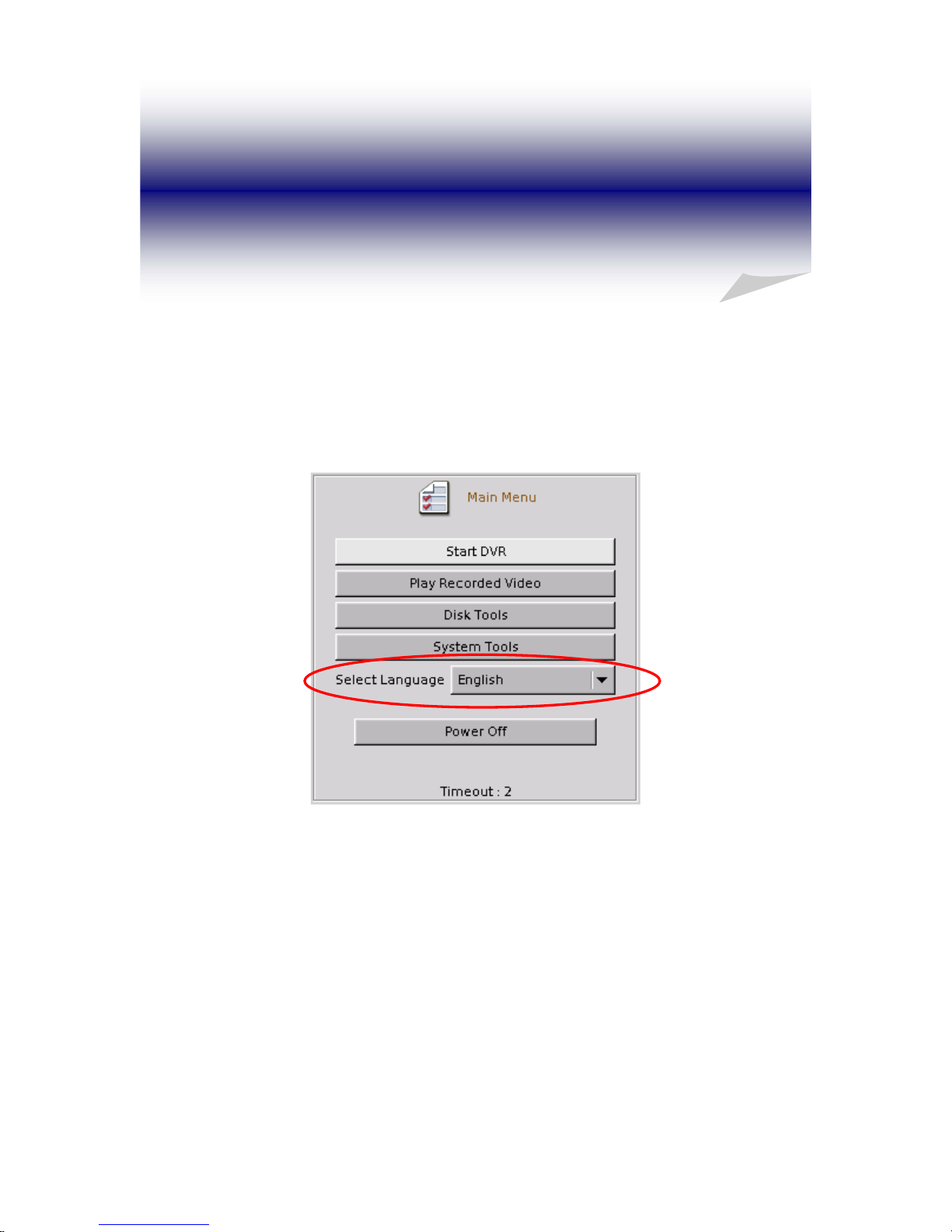
2. Language Selection
You can select your preferred display language at “Main Menu” before starting DVR system.
There are seven languages that are supported in this version- Traditional Chinese, English,
Japanese, French, German, Portuguese, and Spanish.
6
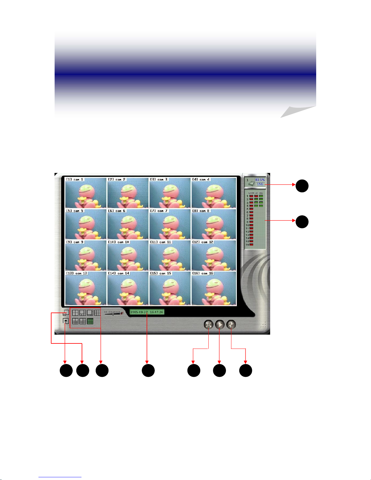
3. Main Screen
After turning on the DVR, launch the DVR program and it will show the following main
screen,
7

The controls in the main screen including:
Function Description
1 Storage Space Indicate the HD free space status
2 Recording/ DI/DO Status Camera recording status and alarm/sensor input
and output status
3 System Setting Quick access to system configuration
4 Playback Quick access to playback mode
5 Full Screen Monitoring Monitor in full Screen
6 Date/Time Display current date and time
7 Display Mode Select display divisions
8 Motion/Alarm to Zoom Activate zooming function when motion or alarm
occurs
9 Sequencer Display in sequence
Note:
Whenever you click this button
, the system will return to the main screen.
8
3-1 Display Mode
There are 7 kinds of Display mode, 4 splits, 6 splits, 8 splits, 9 splits, 10 splits, 13 splits, and 16
splits.
The default display mode is 16 splits. The cameras displayed on each split mode can be
configured in the system setting menu.
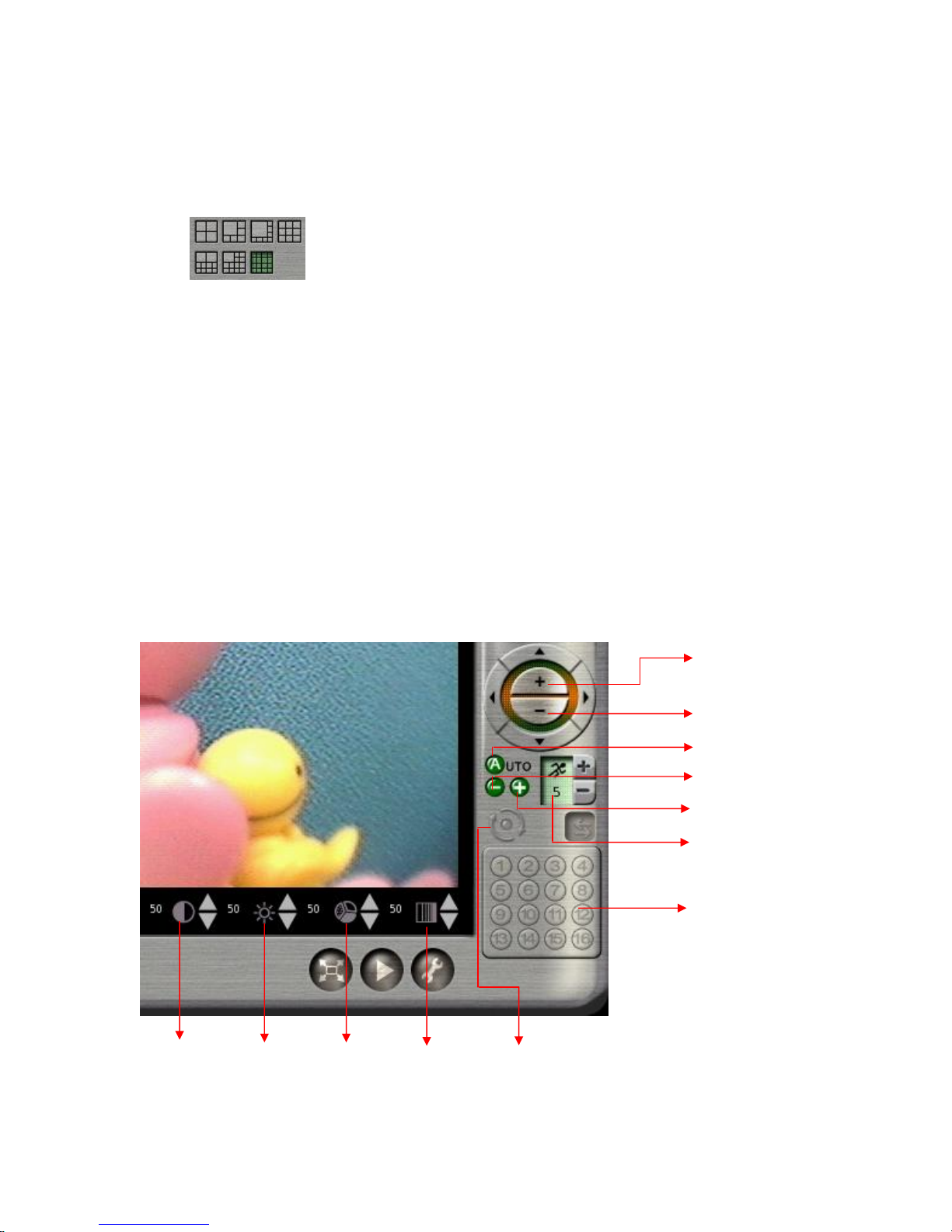
Besides the different kinds of split modes, you can click in a camera image on any split screen
to show the full screen of that specific camera as shown in the example below.
In the full screen mode the “Screen Adjustment Parameters” will locate at the bottom of the
screen. These parameters are “contrast”, “brightness”, “chroma”, and “saturation”.
When a Speed Dome is connected and the system is in full screen mode, PTZ control buttons
will pop up in the lower right of the screen. These controls include “Zoom in”, “Zoom out”,
“Auto Focus”, “Focus Near”, “Focus Far”, and “PTZ Speed”.
Zoom In
Zoom Out
Brightness
Chroma
Auto Pan
Focus Near
Focus Far
Auto Focus
PTZ Speed
Preset Point
Saturation
Contrast
9
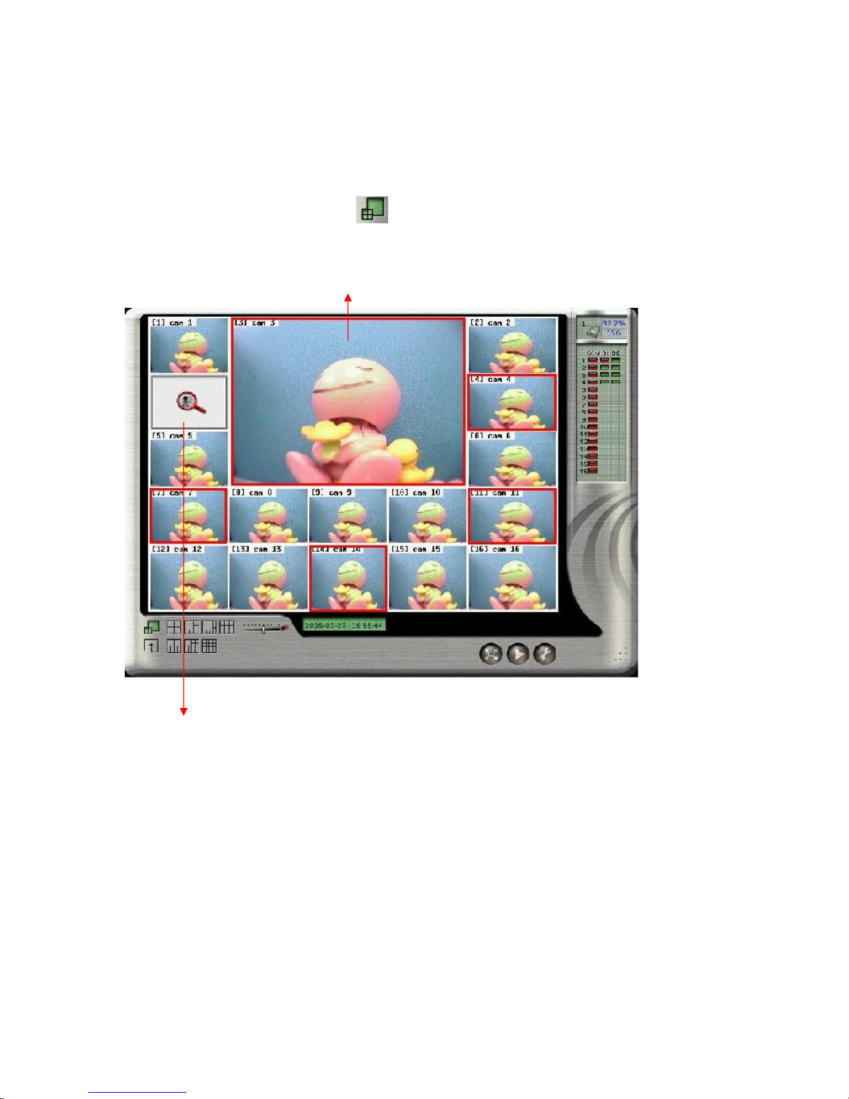
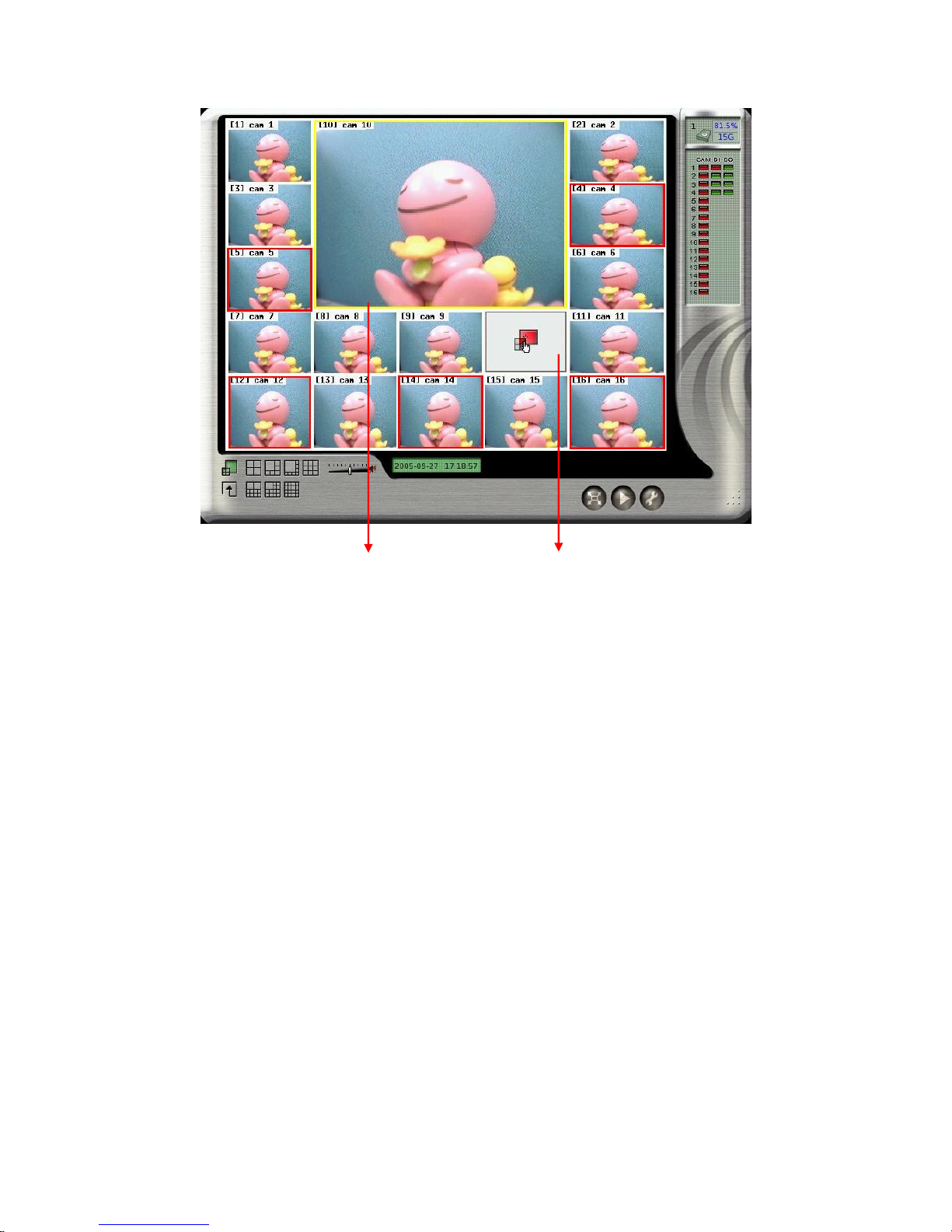
3-2 Motion/Alarm to Zoom
The function of “ Motion/Alarm to Zoom” is zooming in the screen when there is any motion
or alarm occurring. After clicking
icon, it will activate the “Motion/Alarm to Zoom
“mode.
Motion/Alarm Zooming Area
Motion/Alarm Picture
1. At first, you must go to “ Alarm Notice” in “System Setting” menu to set up the channels
that you want to enable the “ Motion/Alarm to Zoom” function. For the “Alarm to Zoom”
function, you need to have further set up in “DI/DO” under “System Setting.” Click “ DI/DO”
in “ System setting and then select “DI->Zoom”. Next, click channels which you want to
enable “Alarm to Zoom” function and then return to the “Main Menu” to click the
“ Motion/Alarm to Zoom” icon. To note that only “DI/DO” and “Motion to Zoom” be set can
the “Alarm to Zoom” function work.
10
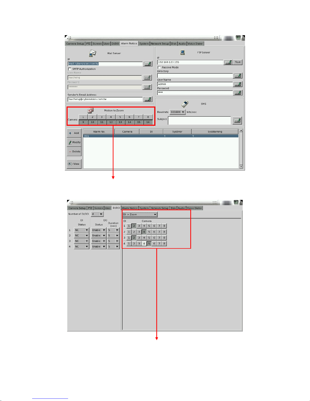
Select the channels you want to
enable “ Motion/Alarm to Zoom”
Select the channels you want to
enable “Alarm to Zoom” function
11

2. When the channel which is enabled the “ Motion/Alarm to Zoom” function occurs motion or
alarm, its’ screen will be zoomed in the “ Motion/Alarm Zooming” area and the original screen
of this channel will be replaced by a “Motion/Alarm Picture”. If the channel is not enabled
the “ Motion/Alarm to Zoom” function, the screen of this channel will not be zoomed and will
not be marked in red frame even there is a motion or alarm in this channel.
3. If there is no other motion or alarm occurring, the current zoomed screen will be continually
kept in “ Motion/Alarm Zooming Area”. If yes, the zoomed screen will be kept in
“ Motion/Alarm Zooming Area” just for three seconds and will be replaced by the one from
any channel waiting for zoomed after three seconds. If there is more than one motion or alarm
occurring at the same time, the zooming rule will be as follows,
a. The previous zooming channel will be the first priority for zooming again and others will
be marked in red frame to wait for zooming in after three seconds. However, the number of
continually zooming the same channel will be limited to three times. After three times,
even this channel occurs motion or alarm again, the motion/alarm zooming area will show
the screen of other channel. If the motion or alarm in one of the channels waiting for
zooming and marked in red frame disappears within three seconds waiting time, this
channel will not be zoomed in and the red frame will disappear.
b. If the previous zoomed channel does not have motion or alarm again, the first priority
being zoomed is the channel of which number is the smallest. For example, if channel #3
and channel #7 occur motions or alarms at the same time, channel #3 will be zoomed firstly
for three seconds and the screen of channel #7 will be marked in red frame to wait for
zoomed after three seconds.
4. Zooming in a specific channel: You can decide just to zoom in a specific channel. When
clicking any channel you want to zoom in, the screen of this channel will be zoomed in to the
“Motion/Alarm Zooming” area marked in yellow color frame and the original screen of this
channel will be replaced by a “locked picture”. Then, the screen of other channels, even
occurring motion or alarm, will not be zoomed in “Motion/Alarm Zooming Area” and it will be
just marked in red color frame. You can click the “ Motion/Alarm Zooming Area” to cancel the
“ Zooming in a specific channel”.
12
Motion/Alarm Zooming Area
marked in yellow color
Locked Picture
13

3-3 Storage S pace
On the right side of the main screen, you can find the free space of hard disks. If there are
more than one hard disk is connected, it will display the status of each HD every 5 seconds.
When you start using a new hard disk (for example, a hard disk with capacity 80GB), the
percentage of free space will be very close to 100% (e.g. 99%), and the color will be BLUE.
However, as recording continues, the available space will diminish. When the remaining
available space is less than 4GB, the display color will change to ORANGE. This serves as a
warning message that the system will soon enter the Recycle Mode; which means, the earliest
recorded data will be replaced by the newest recording data. If you would like to keep all the
data, this is the time to swap a new hard disk.
If the disk has not been changed and the recording continues, the system will go into Recycle
Mode when the hard disk free space is less than 1GB. The color of “Hard Disk Free Space”
will turn RED.
14
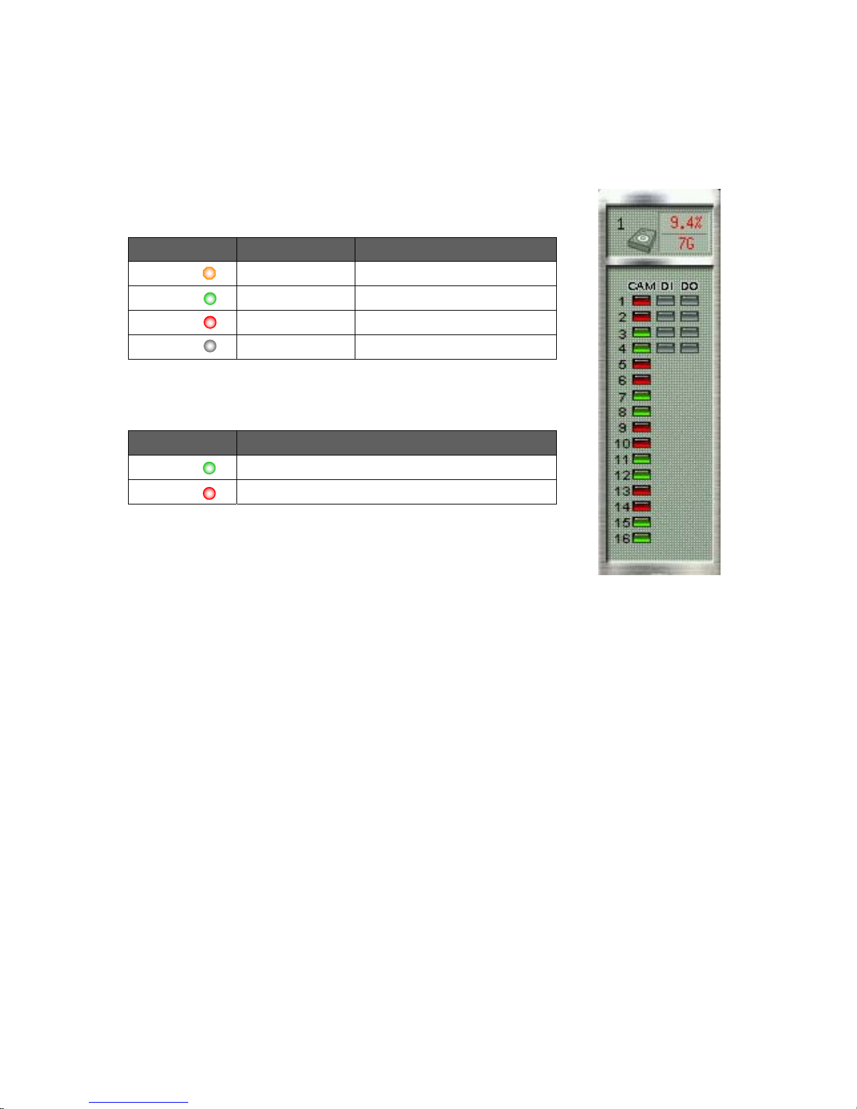
3-4 Recording & DI/DO Status
The first column indicates the recording status of each camera:
Color Recording Mode Status
Orange ( ) Full recording
Green ( ) Motion-sensor Motion not detected
Red ( ) Motion-sensor Motion detected & recording
Gray ( ) No recording
The second and third column shows the status of each DI and DO
device.
Color Status
Green ( ) Device not activated
Red ( ) Device activated
15
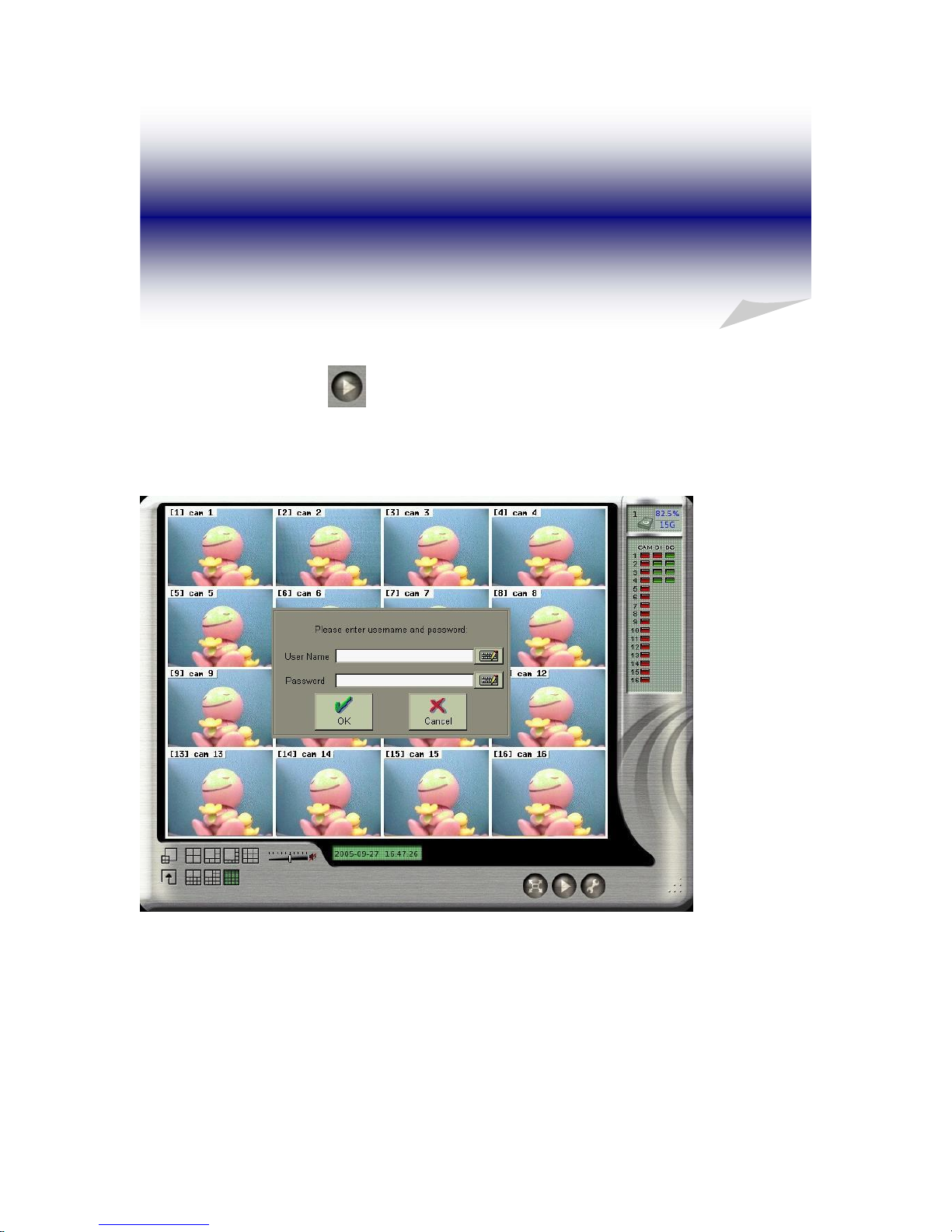
4. Playback
Click the playback icon
on the main screen to enter playback mode. If “Playback
Password Protection” function is enabled (See 4-1 Playback Password Setting), the system will
prompt you to enter User name and Password to enter playback mode as following,
16
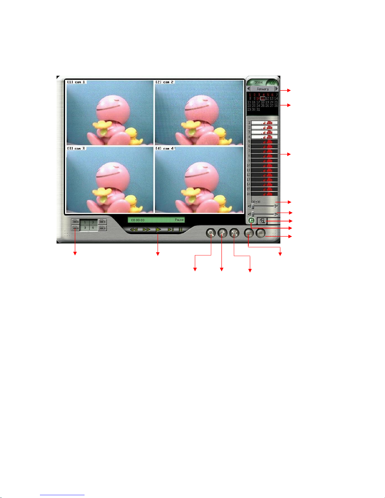
The controls of Playback function are as following,
Browse
Calendar
Status
Search by hour
Search by minute
Time Map
Snapshot/Backup
Play
Camera
Selection
Event
Search
Setup
Full
Screen
17
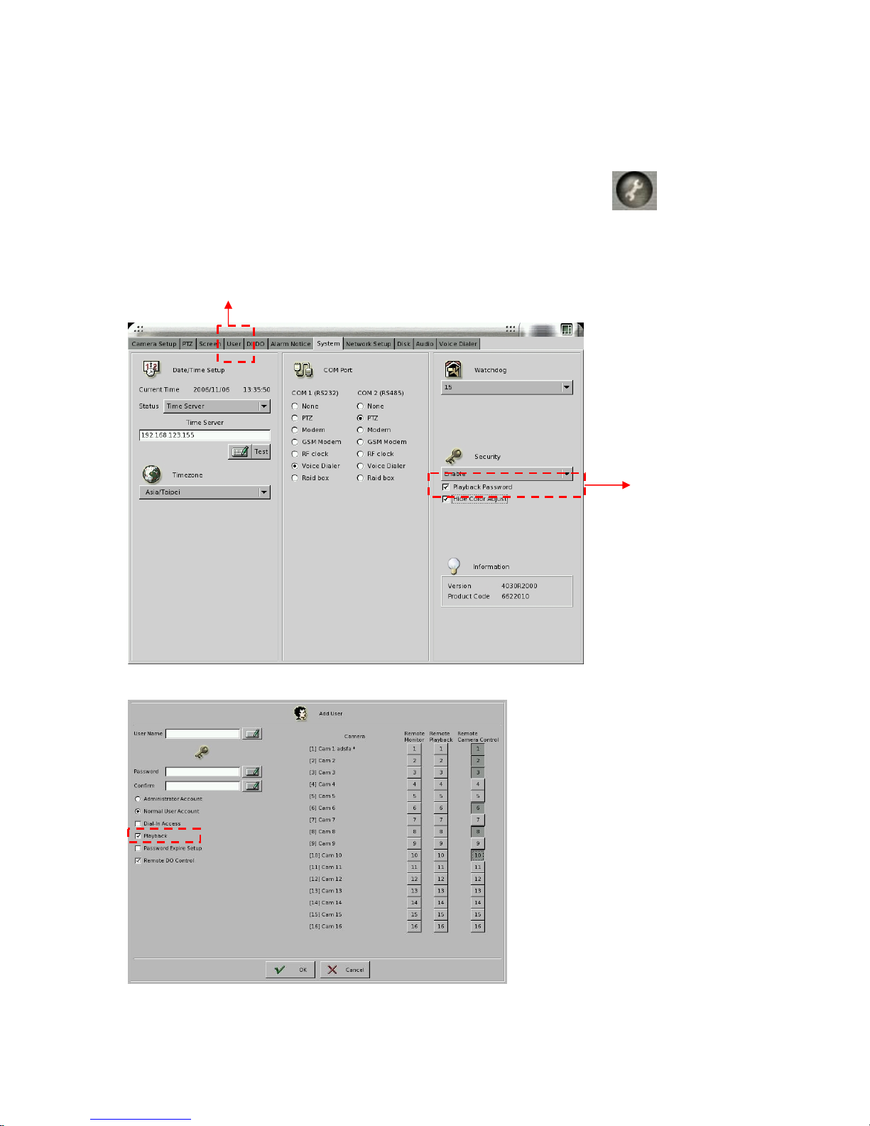
4-1 Playback Password Setting
If you want to activate “Playback Password Protection” function, click in the main
menu to go the “System Setting” as follows. Change the “Security” from “ Disable” to
“Enable” mode and then click “Playback Password”.
Set up User authority
Enable Playback
Password
Then, set up the “User” authority of playback as follows,
18
4-2 Search for Recorded Data
This DVR system provides two modes of “ Search for Recorded Data”. One is “ Search by
time” and the other one is “Search by Event”.
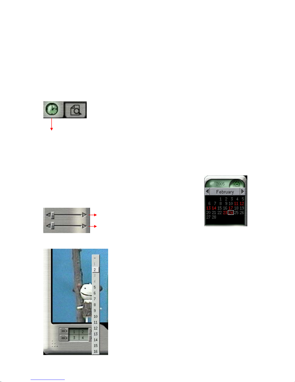
4-2-1 Search by Time
Time Map
When you click the icon of “ Time Map” on the lower right corner of Playback screen, it will
show three kinds of time parameters for users to search and jump to the recorded data by time
directly including “ Calendar, Hour and Minute”.
First, click on the date of the calendar on the upper right corner of the
screen and then select the “hour” and “minute” using the two bars on
the lower right corner.
Hour bar
Minute bar
Next, select the cameras for playback using the buttons at the
bottom of the screen. You can playback up to 4 cameras at the
same time. When you click the camera button, camera numbers
1 to 16 will appear. Select the desired camera to playback.
Choose “ - ” if no camera is to be played back on this screen.
The color of the selected cameras on the right side of the screen
will be in “light blue” background.
Click the Play button to start playback.
19
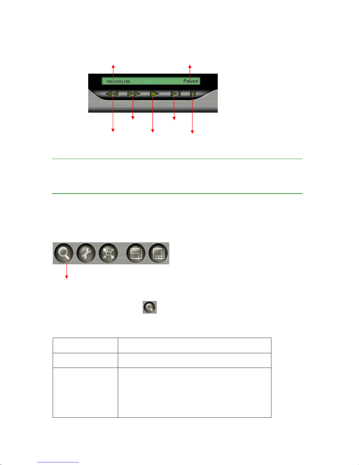
Time
Rewind
Play
Forward Next Frame
Pause
Status
Note:
z You can 2×, 4×, 6× forward by clicking Forward button one more time.
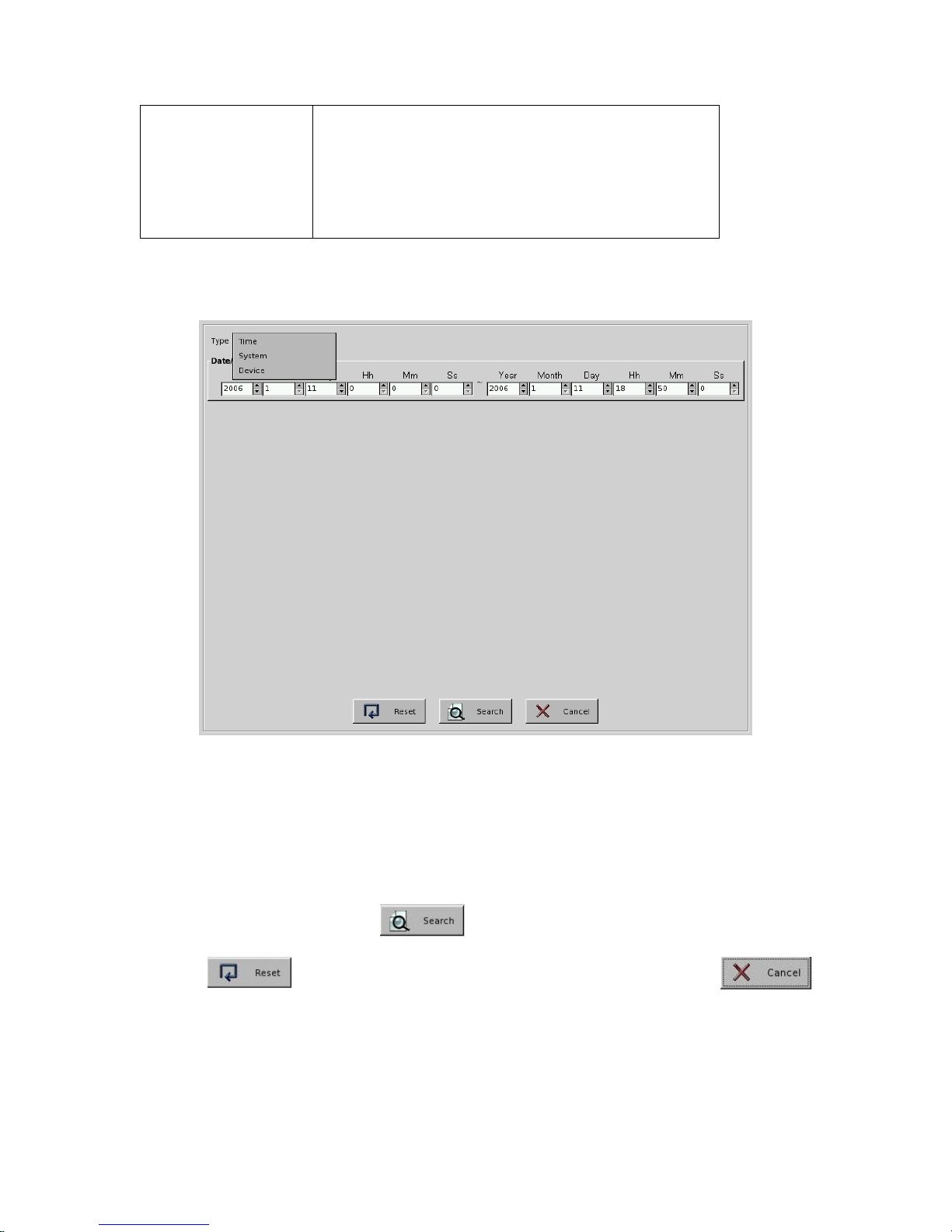
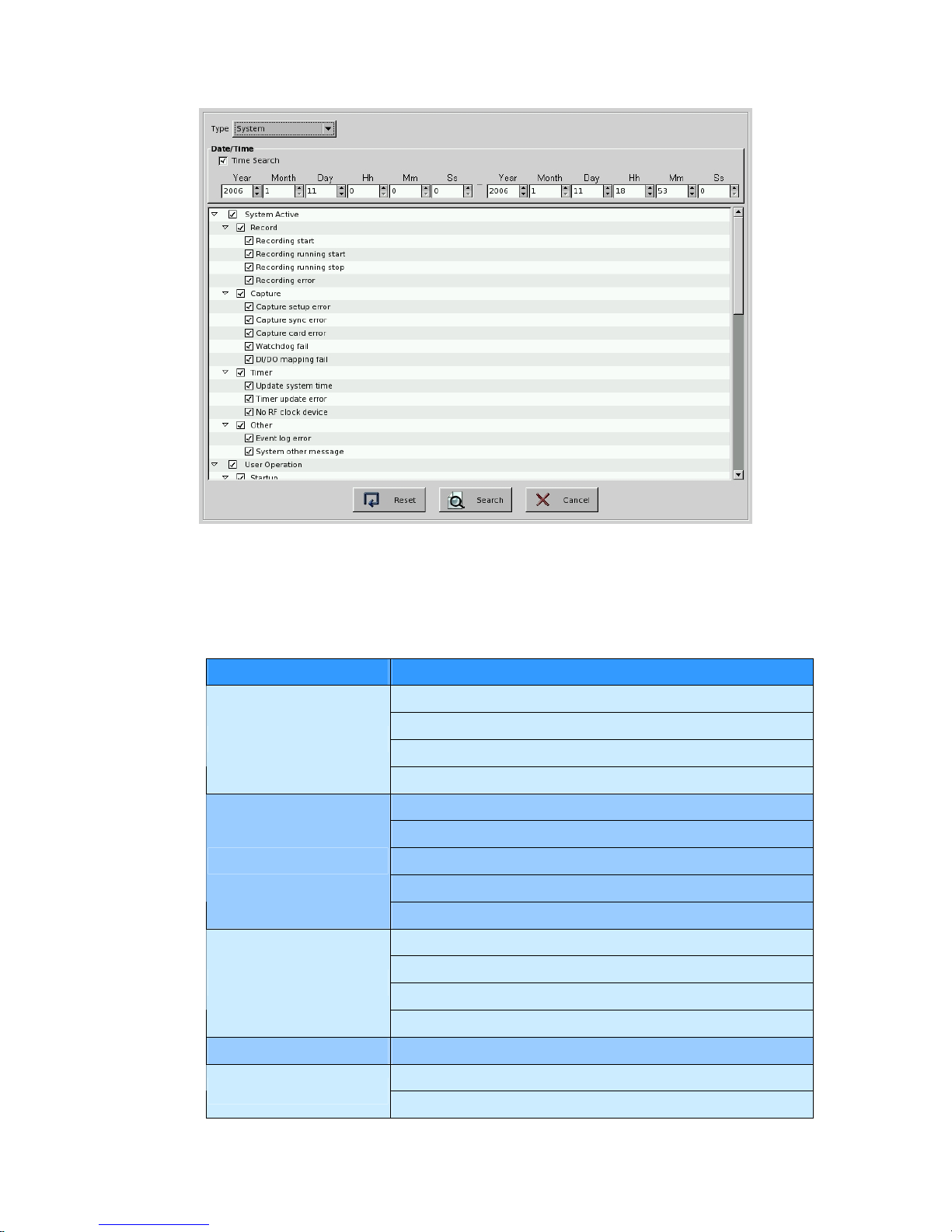
4-2-2 Search by Event
Event Search
Click the “ Event Search” icon
, it will show the “Search Window”. There are three
kinds of event search modes, “ Time, System and Device”.
Search Mode Description
Time Search all of the events within the time range you set up.
System *Search all of the System events within time range
which you set up by marking the “ Time Search” at the
same time or
*Search all of the System events without time boundary
by disable the “ Time Search”.
20
Device * Search all of the Device events within time range
which you set up by marking the “ Time Search” at the
same time or
*Search all of the Device events without time boundary
by disable the “ Time Search”.
z Time Mode:
Step 1: Select “ Time” mode from the Search type.
Step 2: Set up the time of starting point and end point including, Year, Month, Day, Hour,
Minute and Second.
Step 3: Click “ Search” button to execute the “ Event Search”. Click “ Reset
“ button to go back to Default time range. Click “Cancel” button
to stop the event search.
21
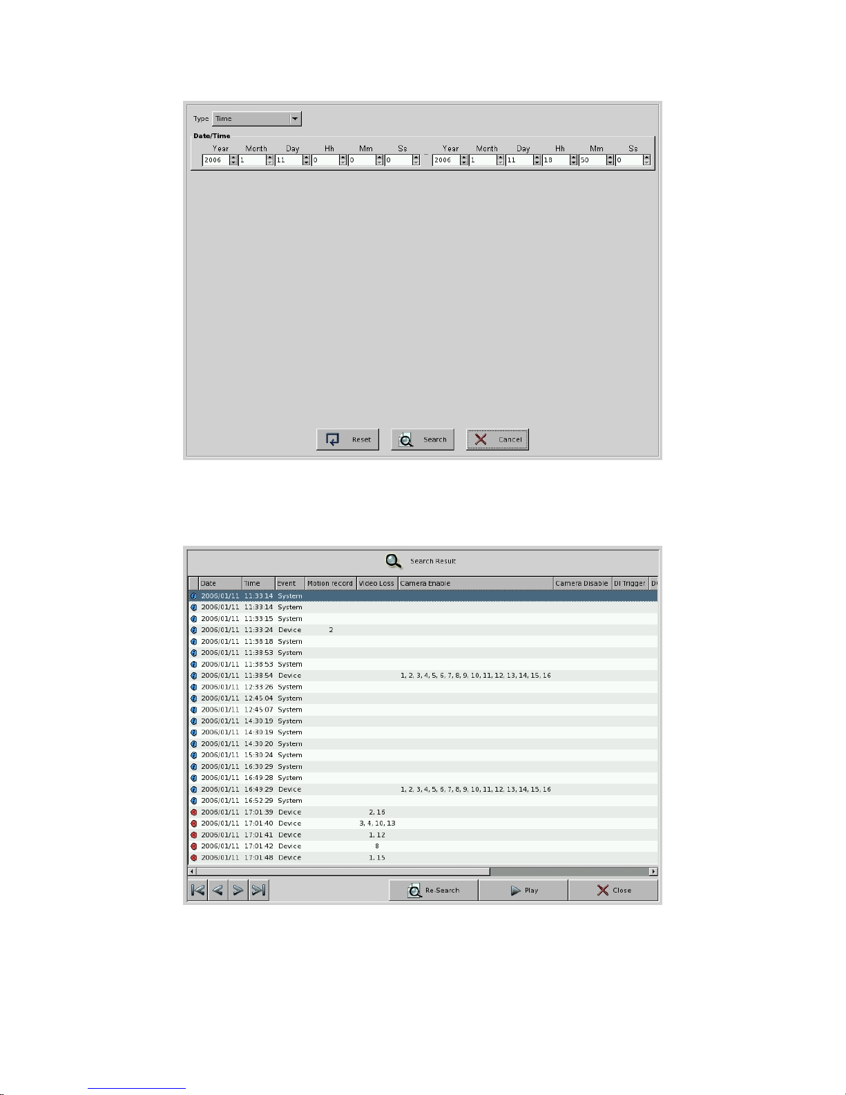
Step 4: Then, the system will open the Search Result Window and show the “Search
Result”.
In the Search Result Window of Time Mode, there will be 11 information columns for each
22

event log including “Date, Time, Event, Type, Motion Record, Remote Alarm Record,
Camera Video Loss, Camera Enable, Camera Disable, DI Trigger, DO Trigger and
Content”. The columns of Date and Time list the event time information. Event column list
“ System”, “Camera” or “Device” event. Type includes “Information ( )”, “Warning( )”, or
“Error( )”. Camera Motion, Camera Video Loss, Camera Enable or Camera Disable
represents the camera with event. The Content column makes the description of System event.
It will show 24 event logs in one page each time and you can click one of the “ Jump button
to go to the event page you want to see.
: Jump to the first page of event search result.
: Jump to the preview page of event search result.
: Jump to the next page of event search result.
: Jump to the last page of event search result.
Step 5: Click button. The system will jump to “Playback Window” as the
following picture. The search result will be shown on the right side of “Playback Window”.
Or click “ Re-search” button and the system will go back to Search
Window.
23
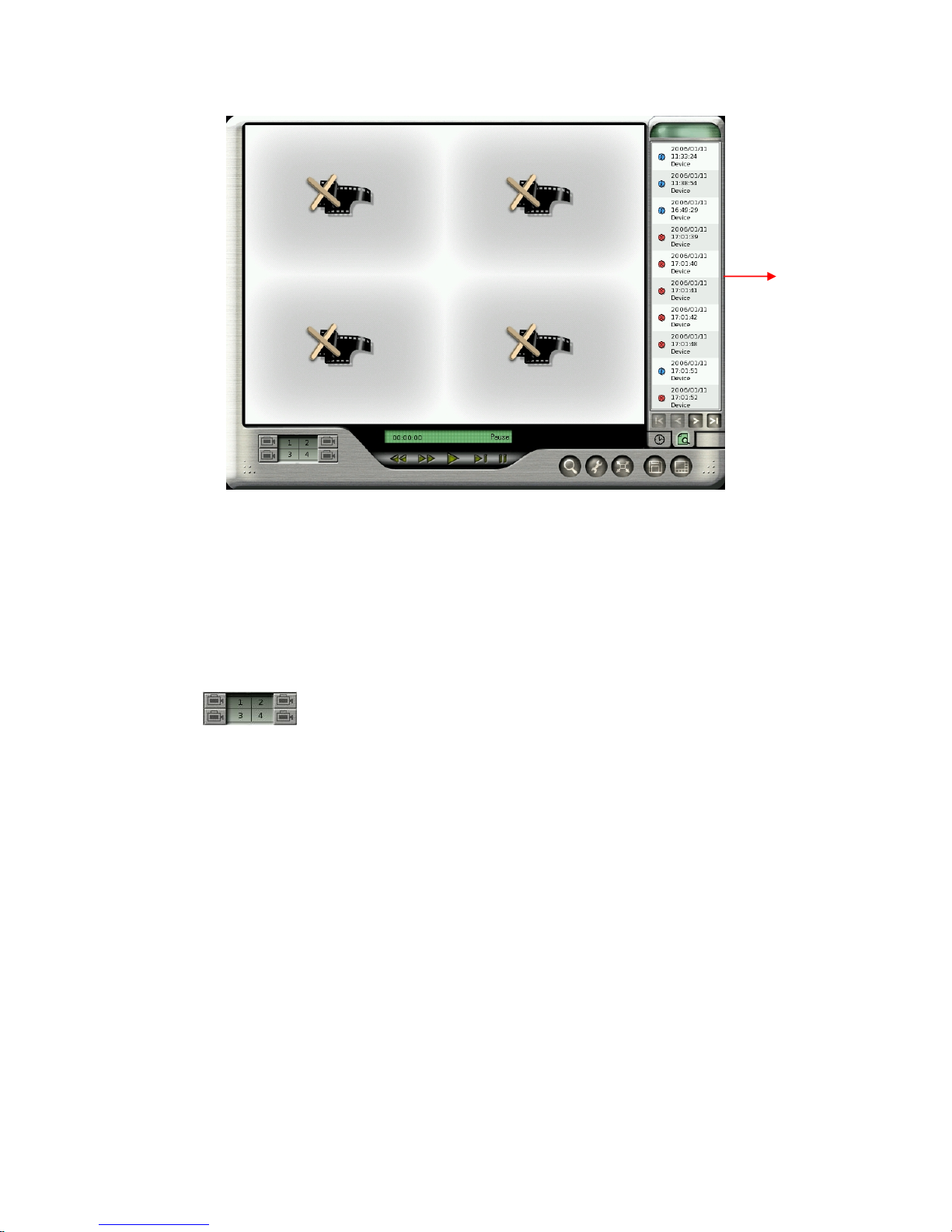
Search
Result
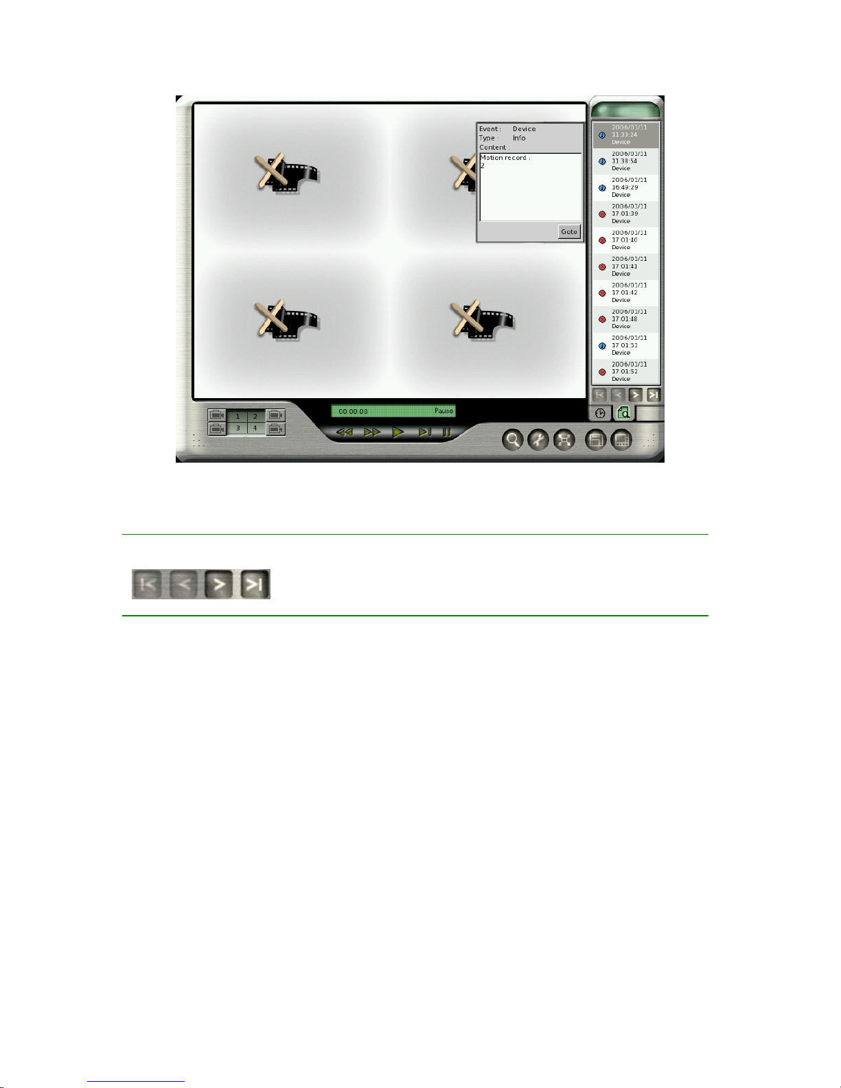
Step 6: Select one of the search logs. It will pop up a window on the left side of Search result
to show the detail information of this log including Event, Type and detail Content. Click
“GoTo” button and it will start to play the event video. This software version can provide four
channels playback at the same time. If this event just happens in four channels ( ex. 2nd, 3rd,
5th, 7th ch) at the same time, the four channel split will just playback these four channel videos.
If this event happens in over four channels ( ex. 2nd, 3rd, 5th, 7th 9th, 11th ch), you can decide
which channel video will be played in the split window by manually setting up the playback
channel
. Otherwise, the system will decide the event playback channel priority
according to the following rule:
z The first priority of playback channel will be the channel of which number is already in
the preset playback channel. For example, Preset playback channel is 1st, 2nd, 3rd, 4th
Ch. The event happens in 2nd, 3rd, 5th, 7th 9th, 11th Ch at the same time. Then, 2nd and
3rd channel will be the first priority to be played on the split window. The rest of two split
windows will play the channel with small number. In this case 5th, and 7th channel will
be played in the split channel too. However, 11th Channel will not be played in the split
window except you can manually change the playback channel.
24
Note:
z System Mode:
It will show 10 event logs in one page each time and you can click one of the “ Jump button
to go to the event page you want to see.
You can search the event by “System” mode and you can also add the “Time Search”
condition to narrow the search range. By marking the various System conditions, you can
decide the search range.
25
The following table lists all of the “System Events”.
Event Group Rule
Recording Start
Recording Stop
Recording running
Record
Recording exception
Capture setup error
Capture sync error
Capture card error
Watchdog Fail
Capture
DIO mapping Fail
Update time to RF clock
Update time to RTC clock
Timer update error
Timer
No RF clock device
Other Event log error
Enter play recorded video Mode
Startup
Enter disk tool menu
26
 Loading...