

Page 1

Before trying to connect or operate this product, please read this manual completely
INSTALLATION &
OPERATION MANUAL
Mega-Pix IP Fixed Dome
Page 2

1
Table Of Contents
SAFETY PRECAUTIONS .............................................................................3
1. PRODUCT FEATURES.............................................................................4
1.1 PRODUCT INSTRUCTIONS .....................................................................4
1.2 PRODUCT FEATURES ...........................................................................5
2. DESCRIPTION OF THE DEVICE .............................................................8
2.1 NAME OF PARTS ..................................................................................8
2.2 THE CONNECTORS ..............................................................................9
2.3 THE USB FUNCTION ..........................................................................10
2.4 POE (POWER OVER ETHERNET).........................................................11
2.5 LENS ADJUSTMENT ............................................................................12
2.6 INSTALLATION ....................................................................................13
3. UPDATING SYSTEM SOFTWARE ........................................................15
4. Network Configuration..........................................................................17
4.1 CABLE CONNECTIONS........................................................................17
4.2 CONFIGURE YOUR IP CAMERA NETWORK SETTINGS ...........................17
4.2.1 Enable DHCP Function.....................................................................................................................17
4.2.2 Set IP Address...................................................................................................................................18
4.3 TCP/IP COMMUNICATION SOFTWARE .................................................19
4.4 TCP/IP INSTALLATION .......................................................................21
4.5 TCP/IP CONFIGURATION SETTING ......................................................22
4.6 CONNECTION TESTING.......................................................................23
5. Operating Instructions for Image Software and Network..................25
5.1 MICROSOFT INTERNET EXPLORER ......................................................26
5.1.1 Connecting the IP camera ................................................................................................................26
Page 3

2
5.1.2 Live Video........................................................................................................................................27
5.1.3 Setup.................................................................................................................................................31
5.2 THE IP CAMERA CMS (CENTRAL MANAGEMENT SYSTEM)...................82
5.2.1 Introduction to the CMS ..................................................................................................................82
5.2.2 Install the CMS in your PC..............................................................................................................83
5.2.3 Login the IP Camera software..........................................................................................................84
5.2.4 Operation..........................................................................................................................................86
6. ADVANCED OPERATION....................................................................100
7. SPECIFICATIONS.................................................................................102
8. Functions of client PC.........................................................................103
APPENDIX 1. –IP camera UPnP How To................................................104
APPENDIX 2. –The ARP function ...........................................................114
APPENDIX 3. –Register as a DDNS member ........................................116
APPENDIX 4. –MPEG4 Bit Rate Lookup Table of IP camera...............120
APPENDIX 5. –PoE Installation Method ................................................121
APPENDIX 6. –FAQ..................................................................................124
Page 4

3
SAFETY PRECAUTIONS
All the following safety and operational instructions to prevent harm or injury to the operator(s) or
other persons should be read carefully before the unit is activated.
WARNING
To prevent fire or shock hazard, avoid exposing this unit to rain or moisture.
Do not block ventilation openings.
Do not place anything on top of the unit that might spill or fall into it.
Do not attempt to service this unit yourself, as opening or removing covers may
expose you to dangerous voltage or other hazards. Please refer all servicing to
your distributor / retailer.
Do not use liquid cleaners or aerosols for cleaning.
To prevent fire or electric shock, do not overload wall outlets or extension cords.
This unit must be grounded to reduce the risk of electric shocks.
CAUTION
RISK OF EXPLOSION IF BATTERY IS REPLACED BY AN INCORRECT TYPE.
DISPOSE OF USED BATTERIES ACCORDING TO THE INSTRUCTIONS.
Page 5

4
1. PRODUCT FEATURES
1.1 Product Instructions
The freshly designed MJPEG and MPEG4 multi-stream compression codec Mega-Pix IP Fixed
Dome provides simultaneous video codec streams of MJPEG and MPEG4. This IP camera not
only supports the 30 / 25 fps frame rate ( in the NTSC / PAL system ), motion detection and a built-in
microphone, but also the day and night, pre- and post-alarm, and PoE functions. The images from
this device have no interlace, and the camera sensor used is the 1/3" VGA CMOS sensor.
In addition, this IP camera hosts the powerful multi profile function which enables the simultaneous
use of different rates of resolution while allowing two video codecs to connect with computers at the
same time. Apart from this, the camera brings you the user-friendly PnP operations, and captures
alarm and scheduled recordings by using an SD card. Besides, the IP camera is equipped with a
vandal-proof body for day and night surveillance. With the specific 3-axis mechanical design, this
dome camera provides a flexible installation for ceiling or wall mounting, and wide angled viewing
which pans 360°and tilts 180°.
This new generation mega-pix IP fixed dome offers a more progressive digitalized image
technology and a user-friendly, controlled interface in the IE Browser to thoroughly update your
surveillance capabilities.
Page 6

5
1.2 Product Features
Camera
Image sensor SONY 1.3M CMOS Sensor (IMX035)
Image co-processor Sony CMOS Sensor IMX035
Minimum Illumination Color 0.2 lux@F1.2
Lens type CS (C mount adaptor can be used)
Shutter time AES:1/30 ~1/1000
Sensor resolution 1280 x 960
Auto iris type DC drive
S/N Ratio 50db with AGC off
Day & Night Mechanical IR filter
Day & Night mode Auto/Day/Night/Schedule
Video Signal
Video output type BNC
Video output level 1.0 Vpp +/-10% 75Ω, composite, Negative (BNC unbalanced)
Synchronization Internal
Video Codec
Video compression
MPEG-4 Part2 (ISO/IEC 14496-2)
Motion JPEG
Resolutions 960P/ 720P / 640 x 480 / 320 x 240 /160 x120 (NTSC : PAL / 60Hz : 50Hz)
Video streaming Simultaneous MPEG-4 (960P/ 720P / 640 x 480 / 320 x 240 /160 x120)
Video Codec – MPEG4
MPEG-4 Frame rate Up to 30 fps at 1280 x 960
MPEG-4 frame rate control Yes
Customized MPEG-4 bit
rate
Yes
MPEG-4 bit rate control Yes
MPEG-4 quality level 5
Video Codec – MJPEG
Motion JPEG frame rate Up to 30 fps at1280 x 960
Motion JPEG rate control Yes
Motion JPEG quality level 5
Audio Signal
Number of tracks Mono 1 channel
Audio sample rate G.711 / G.726
Audio output 1K ohms
Audio input Built-in Microphone / LINE in10k ohms 1.0Vpp
2-Way Audio Full-duplex /Half –duplex/audio off
Image
White Balance Auto / Outdoor / Indoor / Fluorescent
Max AGC control
8X,16X,32X,64X
Mirror Yes
Flip Yes
Exposure Time Adjustable
High speed shutter 1 / 8000 second
Saturation Adjustable
Sharpness Adjustable
Contrast Adjustable
WDR level Adjustable
Brightness Adjustable
Privacy Area Programmable 3 independent zones
Motion Detection Programmable 96 independent zones
Motion Detection Sensitivity 5 levels
Customized motion detection sensitivity Yes
Digital PTZ Yes
Page 7

6
OSD IP Address/Date/Time/ICON
Timestamp Title/Date/Time
Software Platform
Operation System Linux-based system
System Integration
System Requirement Microsoft Windows XP
Remote Access Software Microsoft Internet Explorer 6.0 or above
Network API SDK/CGI/DLL
Recording Software 16 channel free-bundled CMS
Alarm
Alarm triggers Motion Detection, Schedule, Alarm input, System Boot
Alarm application SD recording, SMTP, FTP, Network Storage, CMS recording
Alarm duration Programmable
Schedule counts 3
Hardware
Processors
Texas Instruments DaVinci
High performance 32-bit RISC CPU
DDRII memory DDRII 1Gbit
Flash memory 256Mb
Real-time clock Built-in
Real-time clock battery Built-in
Watchdog Built-in
Firmware upgrade SD Card/HTTP
Fan Yes
Heater Yes
Approvals
FCC Yes
CE Yes
RoHS Yes
Power
DC 12V Yes Max (TBD Watt)
AC 24V Yes
PoE Power over Ethernet (IEEE 802.3af)
Physical Property
Height 50mm
Width 62mm
Length 95mm
Weight 360 g
MTBF 1350000 Hours
Operating Temperature
-20℃ to 50℃ (-4℉ to 122℉)
Operations Humidity 30% to 80 %
Storage Temperature
-20℃ to 60℃ (-4℉ to 140℉)
USB
Type 2.0 * 1
Capacity 24Mbit
Network settings configurable Yes
Network
Ethernet Ethernet (10/100 Base-T), RJ-45 connector
MDIX Yes
Security
2-Level password protection
IP address filtering
User access log
Protocol
HTTP, HTTPS, TCP, RTSP, RTP, RTCP, DHCP, UPnP, ARP, DNS,
DDNS, NTP, PPPoE, 3GPP, FTP, SMTP
Management console Full function
Throughput 19M bit/second
Bandwidth control Yes
Simultaneous users 8
Page 8
7
DDNS Dyndns
IE recording support Yes
Storage
SD Card Support MMC/SD/SDHC 2.0 32MB~32GB
Pre-alarm Yes
File system FAT32/16/12
Recording format JPG/AVI
Network play-back Yes
SD card brand verified A-Data, PQI, Toshiba, Transcend, A-Pacer, Photo Fast
Multi-lingual User Interface
Languages
English, Traditional Chinese, Simplified Chinese, Czech, Dutch
Finland, French, German, Italian, Polish, Portuguese, Spain, Swedish,
Hungarian, Rumanian, Turkish
Device Indicator
Ethernet Link Yes
Ethernet Active Yes
System Operation Yes
System Warning Yes
Accessories
Accessories
USB cable
CD-Rom
C-Mount ring
Power Adapter
Quick installation guide
PTZ Support
Protocol Pelco-D /Pelco-P
I/O Ports
USB 2.0 x1
DHCP/Static IP switch 1
DC IRIS/AES switch 1
Factory Reset Yes
RS-485 Yes
Alarm input 1
Alarm output 1
Audio I/O IN *1 / OUT *1
Ground 1
DC-OUT 1
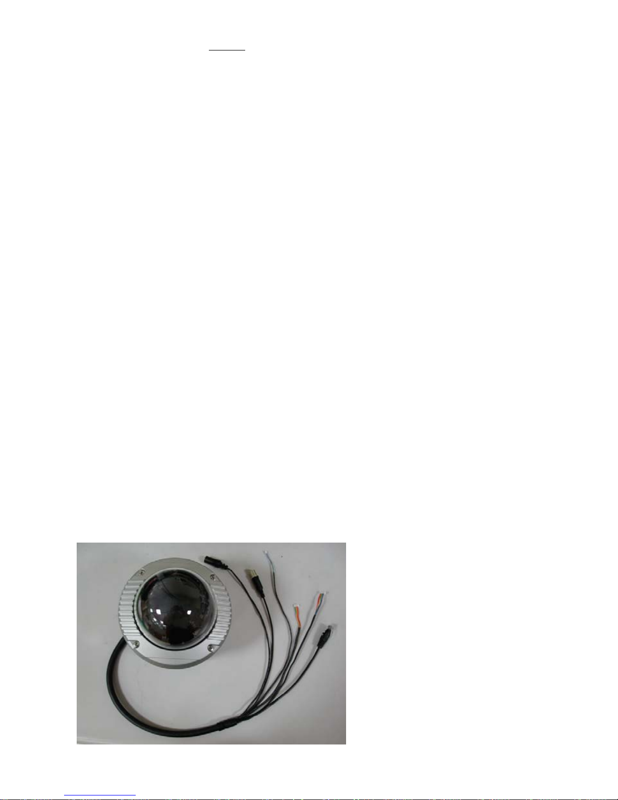
The Surface:
Page 9
8
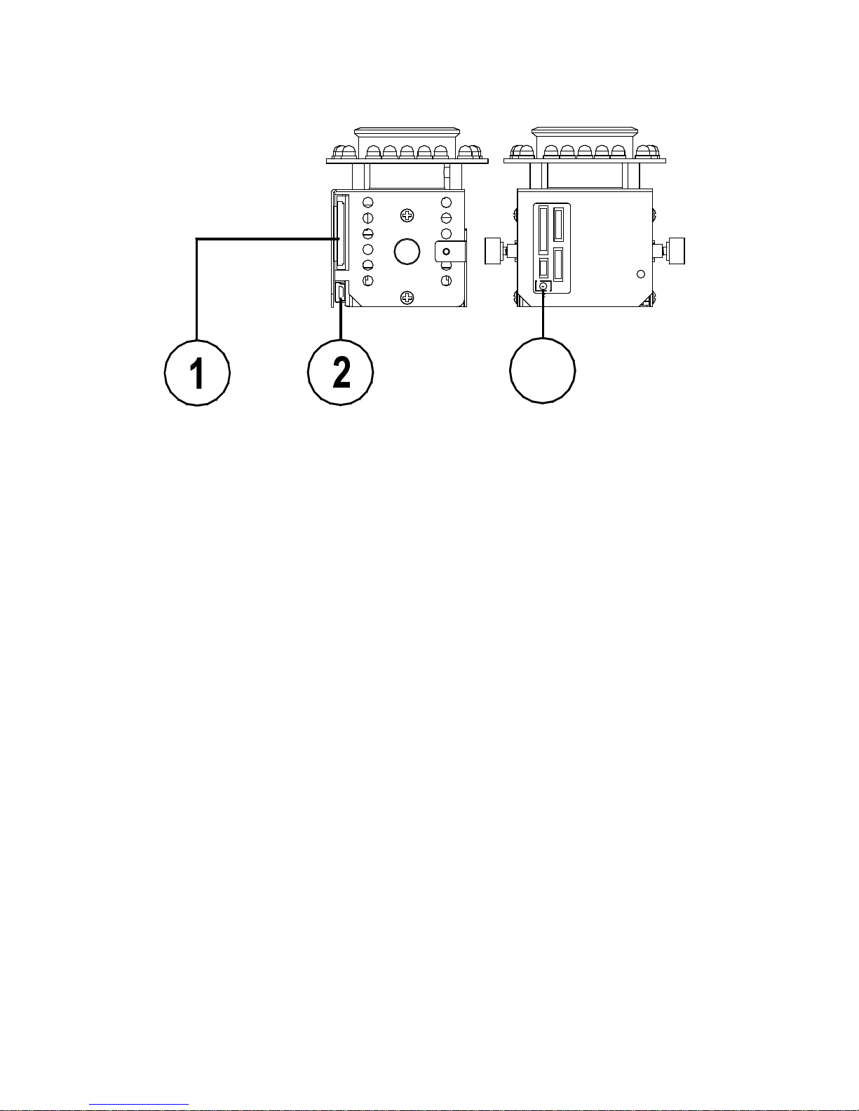
2. DESCRIPTION OF THE DEVICE
2.1 Name of parts
1. SD CARD slot:
This is used for system software updating and archiving / accessing critical images.
2. 5pin MINI USB Port:
You can use a USB device cable to connect the IP camera to the USB port on the PC.
3. RESET :
Recover to factory default.
3
Page 10

9
2.2 The Connectors
1. VIDEO OUT BNC Connector:
The connector provides the unit’s composite video signals to a monitor.
2. ETHERNET 10/100 Connector (PoE):
This is a standard RJ-45 connector for 10/100 Mbps Ethernet networks. PoE (Power over
Ethernet) function: Provides power to the device via the same cable as used for the network
connection.
3. DC12V :
A DC 12V inlet that connects to an external power supply.
4. I/O-B 4 PIN:
5. I/O- A 4 PIN:
6. AC24V 2 PIN:
Page 11
10
2.3 The USB function
By connecting the IP camera with a PC via the USB connector, the IP camera can provide two
different functions.
1. Insert an SD card: As a card reader.
Insert an SD card into the IP camera, then connect to the PC. You might transfer files between
the SD card and the PC. Once you've connected your IP camera to your computer, the
Windows system will detect the connection and ask you what you want to do with your SD
card.
In other words, if the user connects the IP camera with an SD card and the PC via the USB
connector, the IP camera can be used as a normal card reader.
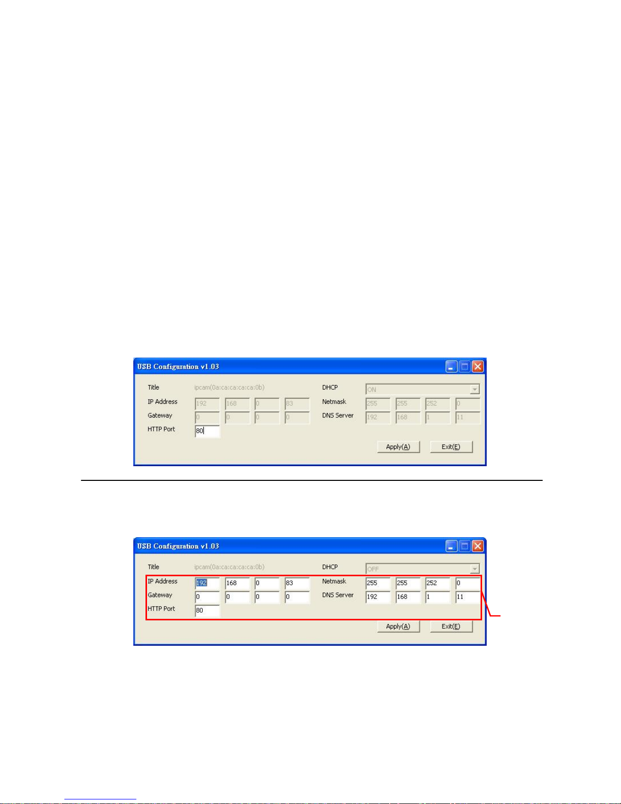
2. Remove an SD card: As a configuring tool.
Before using the USB configuration setting page, please remember to remove the SD card or
your PC will read the SD card and won’t show this window.
DHCP ON
DHCP OFF
(default)
NOTE: After changing the settings, please click the “Apply” button. All of the options
will be effective after removing the USB connector.
NOTE: After the IP address has been changed, please unplug the network cable, then
plug it once again to make sure the network connection is in normal mode.
Network
Setting
Page 12
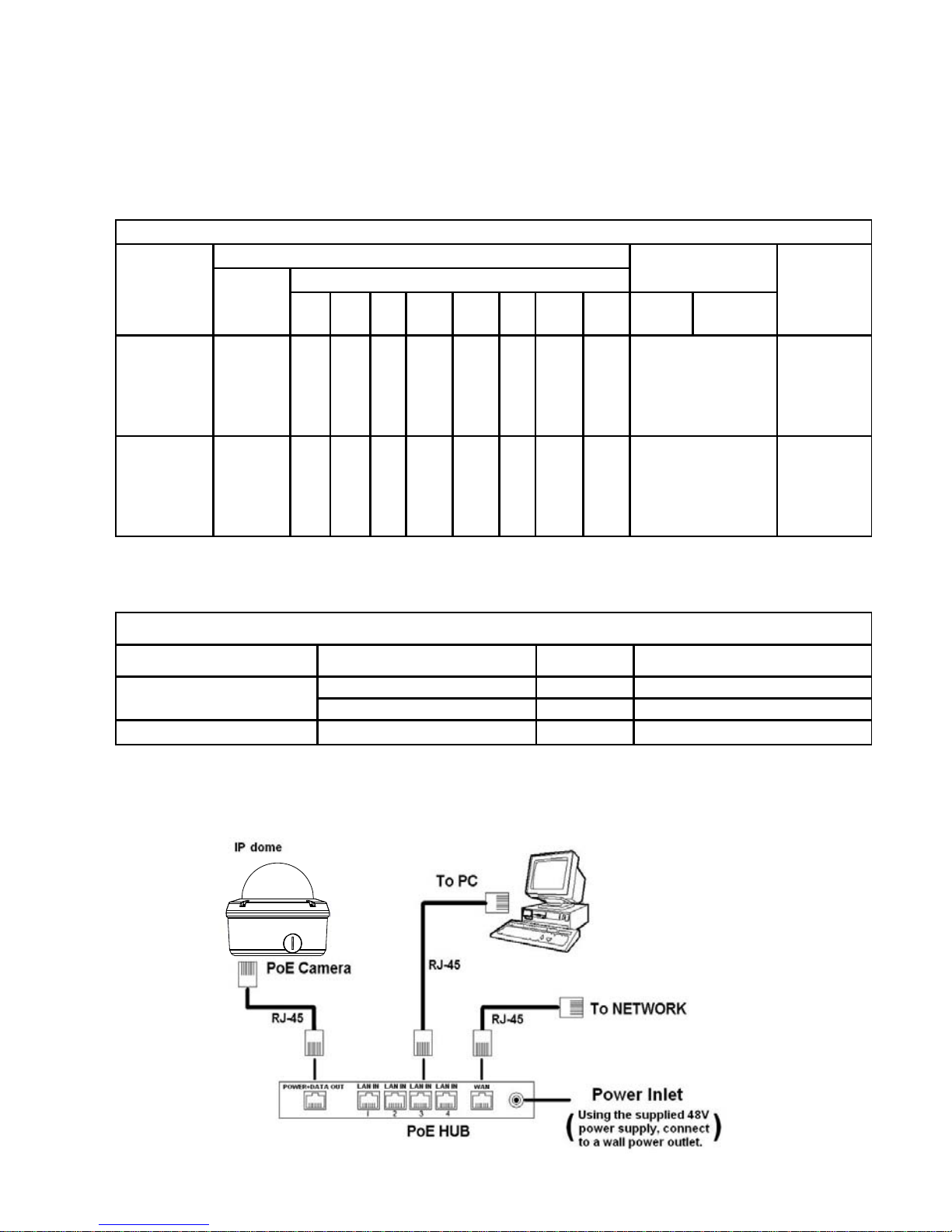
11
2.4 PoE (Power over Ethernet)
These technologies will enable the development of new networked appliances, by providing
power as well as data over existing Ethernet cables.
The Summary Comparison of PoE Standards (Table 1) is listed as follows.
Table 1. Summary Comparison of PoE Standards
SOURCE
Ethernet RJ-45 connector pin number *
LOAD
STANDARD
Source
Voltage
1 2 3 4 5 6 7 8
Load
Voltage
DC Load
Connector
REMARKS
IEEE
802.3af
using data
pairs
48 V DC,
protected
RX,
DC+
RX,
DC+
TX,
DC-
spare spare
TX,
DC-
spare spare (embedded)
Industry
Standard
for
embedded
PoE
IEEE
802.3af
using spare
pairs
48 V DC,
protected
RX RX TX DC+ DC+ TX DC- DC- (embedded)
Industry
Standard
for
embedded
PoE
The compatible PoE Hubs (Table 2), which can be used with the unit, are shown in the tables
below.
Table 2. Compatible PoE HUB
Manufacturer Model Port Note
FSP-804P 4 Port PoE HUB
PLANET
POE-151 1 Port PoE HUB
D-Link
DWL-P200 1 Port PoE HUB
Connect to a PoE HUB
The Standard RJ-45 PIN configuration for connecting with a PoE HUB is shown below.
Page 13

12
2.5 Lens adjustment
Before adjusting the lens, the user has to remove the cover of the dome. 1) Loosen the screws
holding the camera mount and then 2) carefully lift the cover up. After all adjustments
completion, attach the dome cover to the camera.
Focus adjustment:
(1) Loosen the fixing screws on the Zoom ring and Focus ring.
(2) Adjust the angle of view with the Zoom ring and adjust the focus with the Focus ring for
the best picture resolution.
(3) After lens adjustment completion, tighten both the Zoom ring fixing screw and the Focus
ring fixing screw.
Zoom ring
Focus ring
Page 14
13
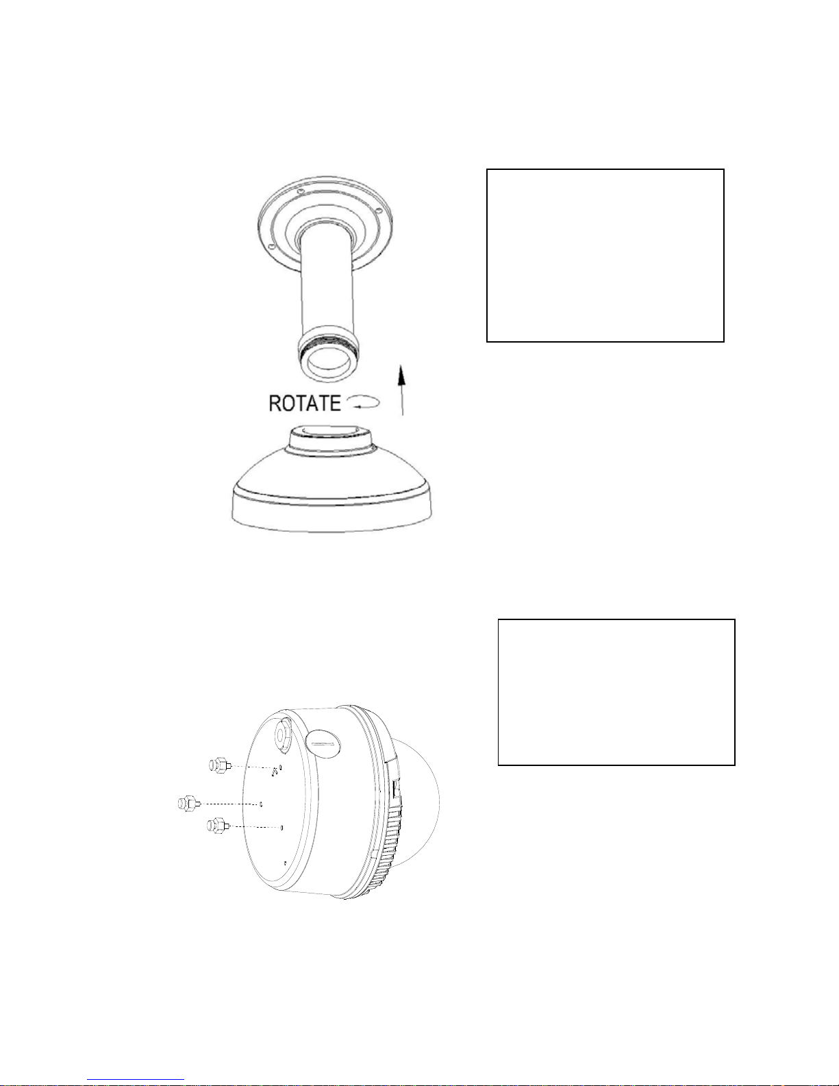
2.6 Installation
Hardware Installation
Follow the steps below to install the dome network camera:
Figure 1.
Figure 2.
Step 1.
Secure the mount base to the
wall / ceiling and rotate the
mount cap into the mount base
( see figure 1 ).
Step 2.
Use the 3 rotating screws to fix
the dome camera bottom tightl
y
( see figure 2 ).
Page 15
14
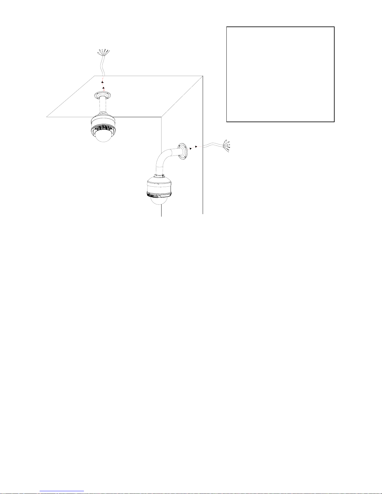
Figure 3.
Step 3.
Pass the cable through the
mount base, then rotate the
dome camera into the cap. The
installation is complete ( see
figure 3 ).
Page 16

15
3. UPDATING SYSTEM SOFTWARE
Please follow the instructions and the diagram below to set up the system.
If the system software of the IP camera needs to be upgraded, please take the following steps to
safely process it.
Important: Before carrying out the following procedures, please ensure the SD card is
working and the file of the system firmware is intact
1. Create a directory named UPGRADE (upper-case or lower-case letters are no difference) in the
SD card if it does not exist.
2. Copy the file of UPDATE.BIN to the UPGRADE -directory.
3. If the IP Camera is running, please power it off first.
4. Insert the SD CARD into the IP Camera.
5. Remove the Ethernet cable from the RJ-45 port and then power on the IP Camera.
6. In 5 to 10 seconds, a message reading "UPDATE PROCESSING" will show up on the screen on
a blue background; if not, please check out steps 1 to 6 carefully or else inform your technical
support while ignoring the following steps.
7. DO NOT power off the IP Camera while this update process is running until the message
"UPDATE OK RESET PLEASE" appears on the screen; it might take 15 to 30 seconds to
appear.
8. If the message "UPDATE NG RESET PLEASE" appears rather than "UPDATE OK RESET
PLEASE", please write down the error messages shown on the screen and inform your
technical support, while ignoring the following steps.
9. Power off the IP Camera when this update process is finished, then remove the SD card from
the IP Camera.
10. Reconnect the Ethernet cable to the RJ-45 port if necessary.
11. Power ON the IP Camera and it will work normally if the entire update procedure goes correctly.
12. Verify the version of the system software.
Page 17

16
WARNING
:
Steps 1 to 2 have to be done on a PC.
Make sure the file of UPDATE.BIN is a correct one in step 2, or the IP Camera will not
work normally after being updated.
If the power of the IP Camera is suddenly lost in step 7, please remove the SD card
first and turn on the IP Camera next to test its operation. If the IP Camera remains
working normally, please go back to step 3; otherwise, please inform your technical
support.
In step 9, if the SD card is not removed and the IP Camera does not get online as well,
the updating process must be repeated again after rebooting the IP Camera.
Make sure that the SD card is inserted in a correct position in step 4, or the IP Camera
will suffer permanent physical damage.
If the message "CSUM ERROR" appears in step 7, it implies a problem in the file of
UPDATE.BIN.
Don’t interrupt the process while the unit is updating itself; proceed with an SD
card not including any system software of the unit, or else the unit will crash.
Page 18

17
4. Network Configuration
4.1 Cable Connections
Please follow the instructions below to connect your IP camera to a computer or a network and to
choose a proper RJ-45 cable configuration for connections.
Physical specifications of the RJ-45 cable for Ethernet
Wire Type Cat. 5
Connector Type RJ-45
Max. Cable Length 100 m
Hub Wiring Configuration Straight Through
PC Wiring Configuration Straight Through
4.2 Configure Your IP Camera Network Settings
Upon connecting with the network hardware, you need to activate the network function and
configure the proper network settings of the IP camera.
4.2.1 Enable DHCP Function
This function can onl
y
work if the LAN, which the unit is connected to, has a DHCP server. If the
DHCP server is working, please turn on to use the DHCP protocol; now the IP CAMERA will
obtain an IP address automatically from the DHCP server. In this instance, please skip section
4.2.2 (Set IP address) and follow section 4.3 (TCP/IP Communication Software).
Note: T he IP D ome camera so ftware default s etting is DH CP OF F. Users ca n buil d the
camera working en vironment with a st atic IP address. T he defa ult st atic I P is
192.168.1.168. You can set a n IP a ddress f or t he camera if t he L AN u nit isn’ t
connected to a DHCP ser ver. Or turn on t o u se the DHCP p rotocol if t he D HCP
server is working i n the LAN, The camera will obtain an IP address automatically
from the DHCP server. The camera is linked by its Video Out connection via a BNC
connector to a monitor's Video In c onnection. If this connection is there, you can
see som e information o n the monitor screen, such as t he ca mera factory default
Static IP address.
Page 19

18
4.2.2 Set IP Address
You need to set an IP address for the unit if the LAN unit isn’t connected to a DHCP server.
Otherwise, please follow the instructions given below:
Set the IP, MASK and GATEWAY. The following is a sample setting.
IP: 192.168.1.X
MASK: 255.255.255.0
GATEWAY: 0.0.0.0
NOTE: When only one unit of the IP camera is connected to a computer or LAN, you can
freely assign an IP address for the IP camera. For example, there is a range of IP
camera IP addresses from 192.168.1.1 to 192.168.1.255. You can pick one for use
from the range of the IP. It’s not necessary to set MASK and GATEWAY; leave the
settings as default.
When an IP camera is connected to a WAN, you must acquire a unique,
permanent IP address and correctly configure the MASK and GATEWAY settings
according to your network architecture. If you have any questions regarding
those settings, please consult a qualified MIS professional or your ISP.
NOTE: When connecting to a network, each connected IP camera must be assigned a
unique IP, which must be in the same class type as your network address. IP
addresses are written as four sets of numbers separated by periods; for example,
192.168.1.1 Therefore, if the connected network is identified as Class C, for
example, the first three sets of numbers of the IP camera IP address must be the
same as the network address. If the connected network is identified as Class B,
the first two sets of numbers of the IP camera IP address must be the same as the
network address. If you have any questions regarding these settings, please
consult a qualified MIS professional or your ISP.
Page 20
19
4.3 TCP/IP Communication Software
Follow the procedure below to install the TCP/IP communication program in your computer.
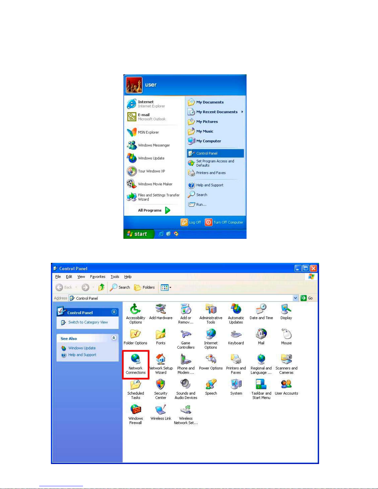
1. Click Start, and then click Control Panel.
2. Double click the Network Connections icon to enter the windows.
Page 21
20
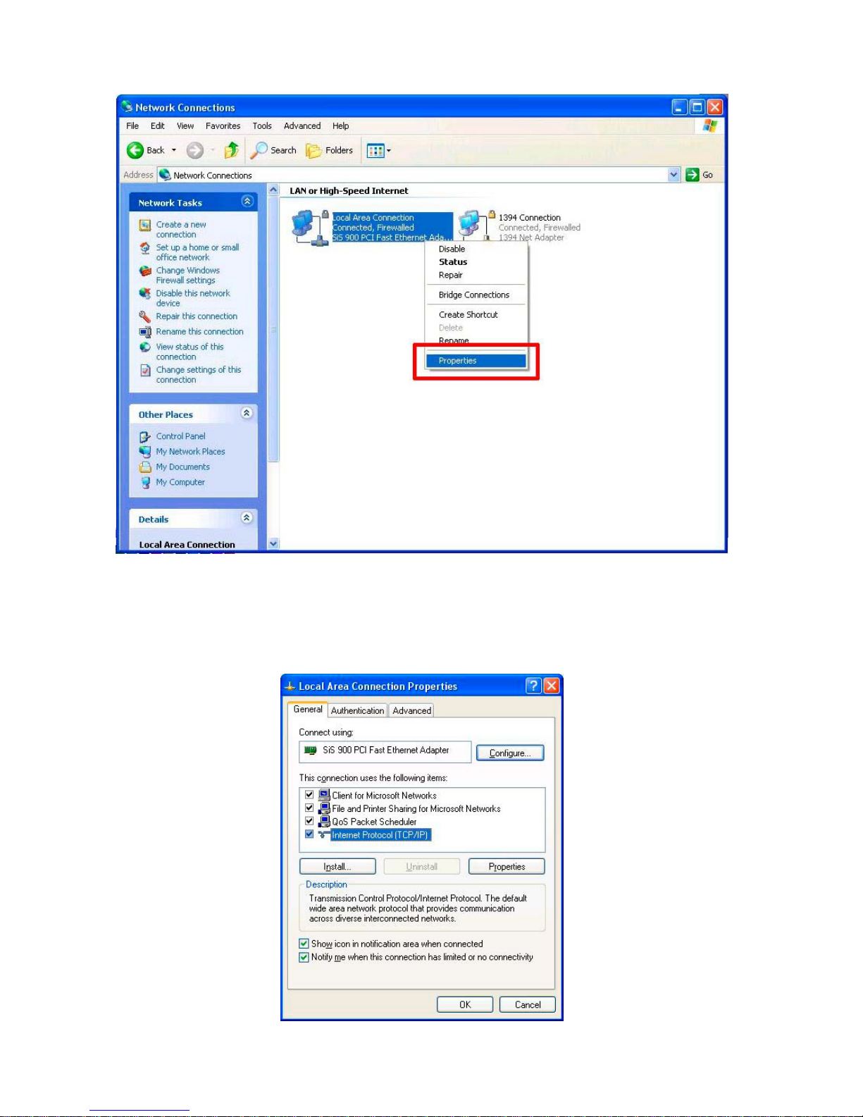
1. Right-click your network connection, and then click Properties.
2. On the General tab, check if the Internet Protocol (TCP/IP) is included in the list. If the
TCP/IP is included, please process section 4.5. If it is not included, please follow section 4.4
to install the TCP/IP.
Page 22
21
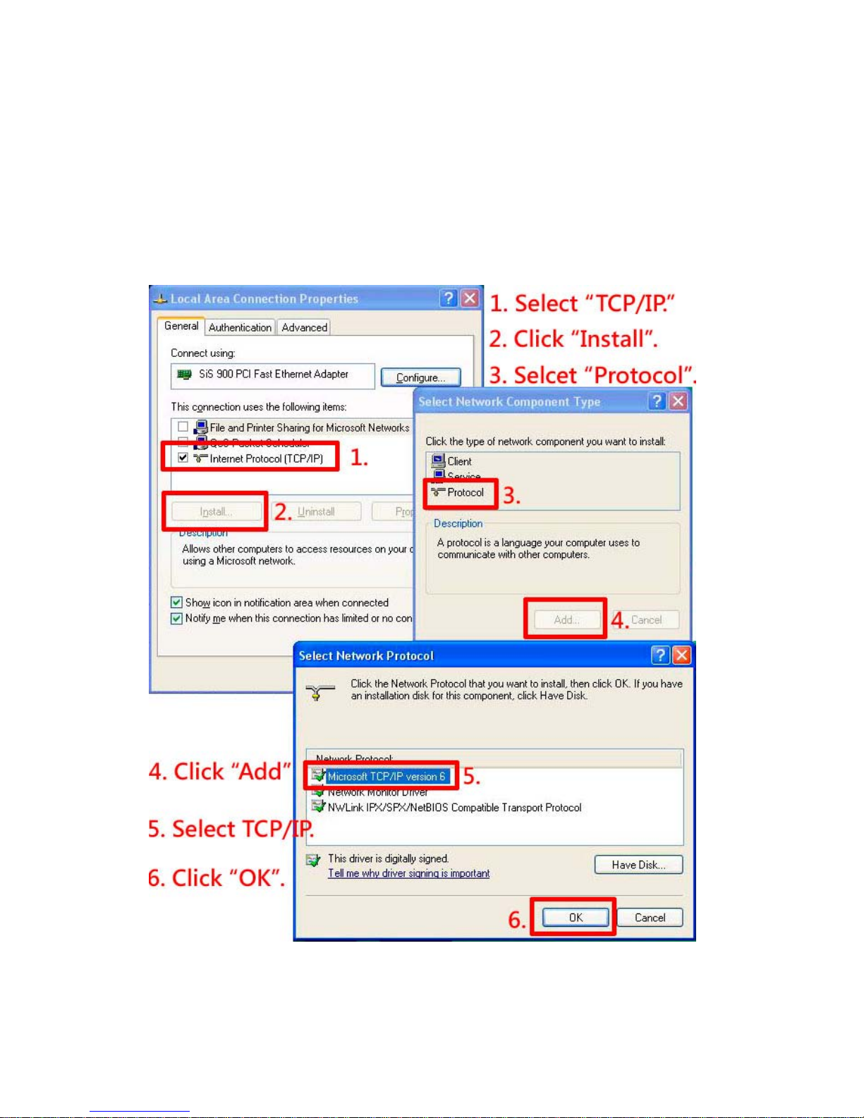
4.4 TCP/IP Installation
On the General tab of the Connection Properties, under “This connection uses the following
items”, click Internet Protocol (TCP/IP). Then click Install. Select Protocol from the network
component type then click Add. Select Microsoft TCP/IP from the network protocol then click
OK.
Click Close to return to the Network Connections window.
Page 23
22
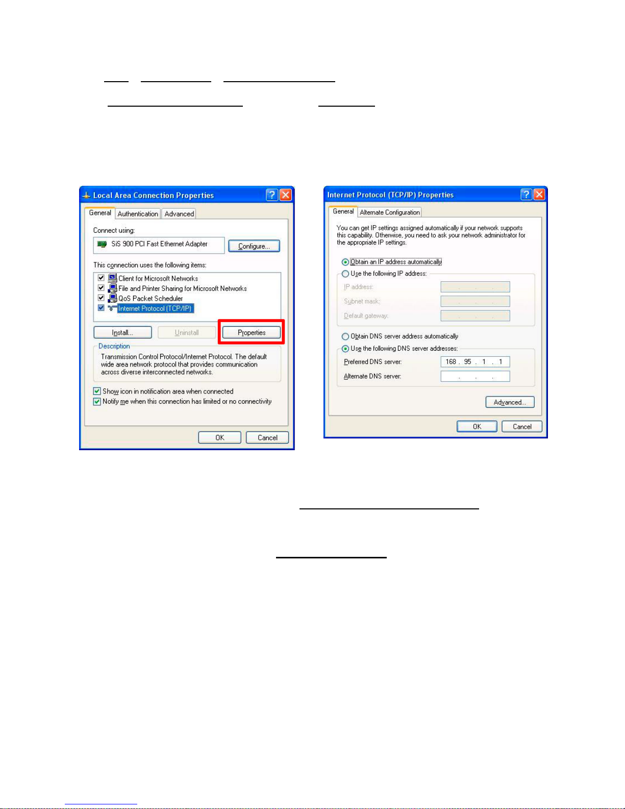
4.5 TCP/IP configuration setting
Click Start > Control Panel > Network Connections.
Select Internet Protocol (TCP/IP)
, and then click Properties.
Before processing the IP camera installation in a WAN, please make sure the Internet
connection works properly. If not, please contact your ISP provider.
If you are using a DHCP server, please select Obtain an IP address automatically
. Any
assigned IP address for the connected IP cameras must be in the same class type as the server.
If there is no DHCP server, please select specify an IP address
enter the IP address, subnet
mask and default gateway of your choosing of your PC. This IP address must be different from
other network IP devices but in the same class type.
NOTE: The IP address of an IP camera in a network must be unique to itself as opposed
to those of the other chosen PCs, but in the same class type.
Page 24
23
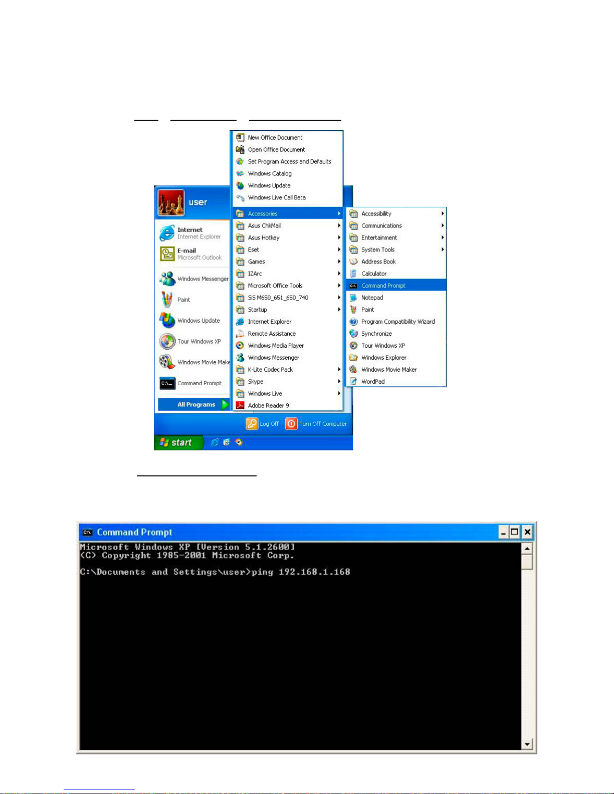
4.6 Connection Testing
With the previous settings, follow the instructions below to ensure whether you have established
the connection successfully.
1. Click Start
> All Programs > Command Prompt.
2. Enter ping XXX.XXX.XXX.XXX
(the camera’s IP address), then enter. (See the sample
screen below).
** This is the IP address for an IP camera that is assigned for the connected IP camera.
Page 25
24
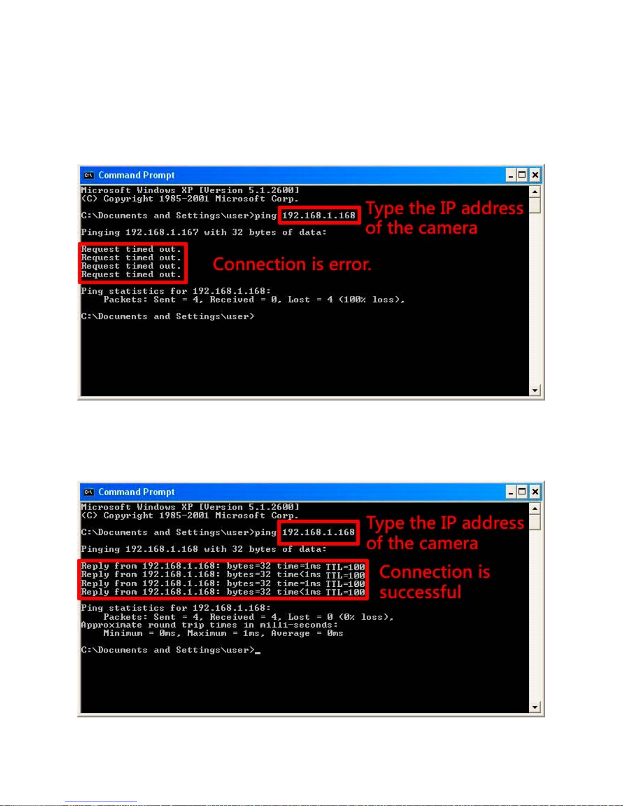
If you receive a response as in the sample screen below, the connection hasn’t been
successfully established. Please re-check all the hardware and software installations by
repeating sections 4.4 and 4.5. If you still can’t establish the connection after rechecking, please
contact your dealer.
If you receive a response as in the sample screen below, you have successfully made the
connection.
Page 26

25
5. Operating Instructions for Image Software and Network
Two choices of software are available for linking with the IP camera: (1) the Microsoft Internet
Explorer; and (2) the IP camera viewer software, a network browser in a PC which provides the
functions of monitoring remote zones or watching recorded data through the TCP/IP protocol.
The details are listed as follows.
RJ-45 PIN configuration for Ethernet
Physical specification for Ethernet
Wire type Cat. 5
Connector type RJ-45
Max. cable length 100 m
Hub wiring configuration Straight Through or Cross Over
PC wiring configuration Straight Through or Cross Over
PIN NO. PIN Assignment
1. TX +
2. TX -
3. RX +
4. Not Connected
5. Not Connected
6. RX -
7. Not Connected
8. Not Connected
1 2 3 4 5 6 7 8
RJ-45 socket
Page 27
26
5.1 Microsoft Internet Explorer
5.1.1 Connecting the IP camera
1. Start up the Microsoft Internet Explorer, and then follow the steps below to connect the IP
camera.
2. Click on the URL block at the top of the window.
3. Enter the URL address of the IP camera into the URL block and press the “Enter” button to
enter the home page.
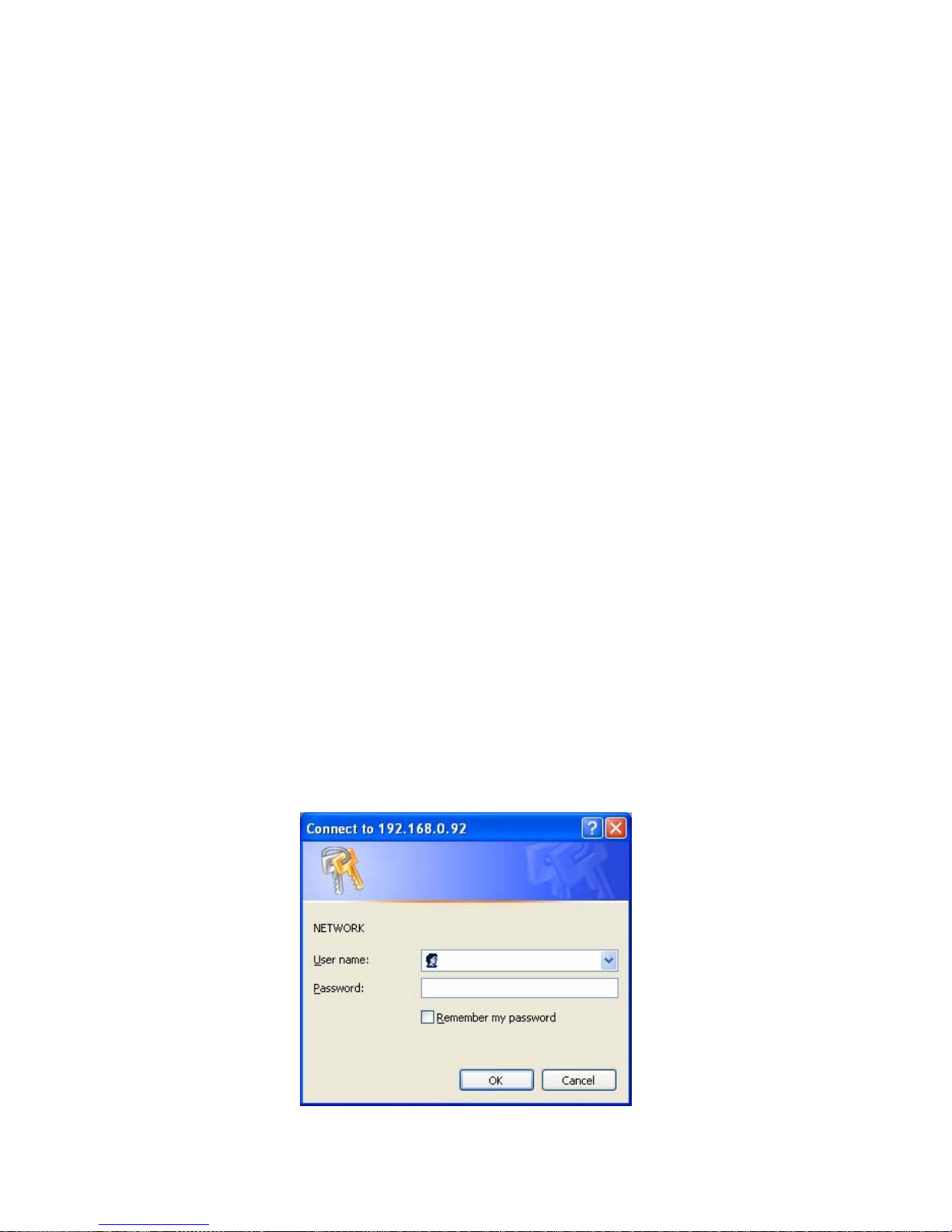
4. Enter the "User Name" and "Password" in the appropriate spaces.
5. Click on the “OK” button to set your entries, and automatically exit the page.
NOTE: The default "User Name" and "Password" are admin and 9999, respectively.
NOTE: The page headlined "Enter Network Password” is shown below. Please enter the
user name and password of the IP camera when you see it. If either the user name
or th e p assword is in correct, please check the i nput data and recti fy i t as
necessary.
NOTE: Once authorized successfully, the login page will not appear again until you close
the window and reconnect it.
NOTE: The initial sequence of proceeding is to type in your IP address and click the "Enter"
button to access the home page. If and when you revise or change data in the "SYSTEM
USERS" page, the sequence will alter to initially show the "Enter Network Password"
page.
Page 28
27
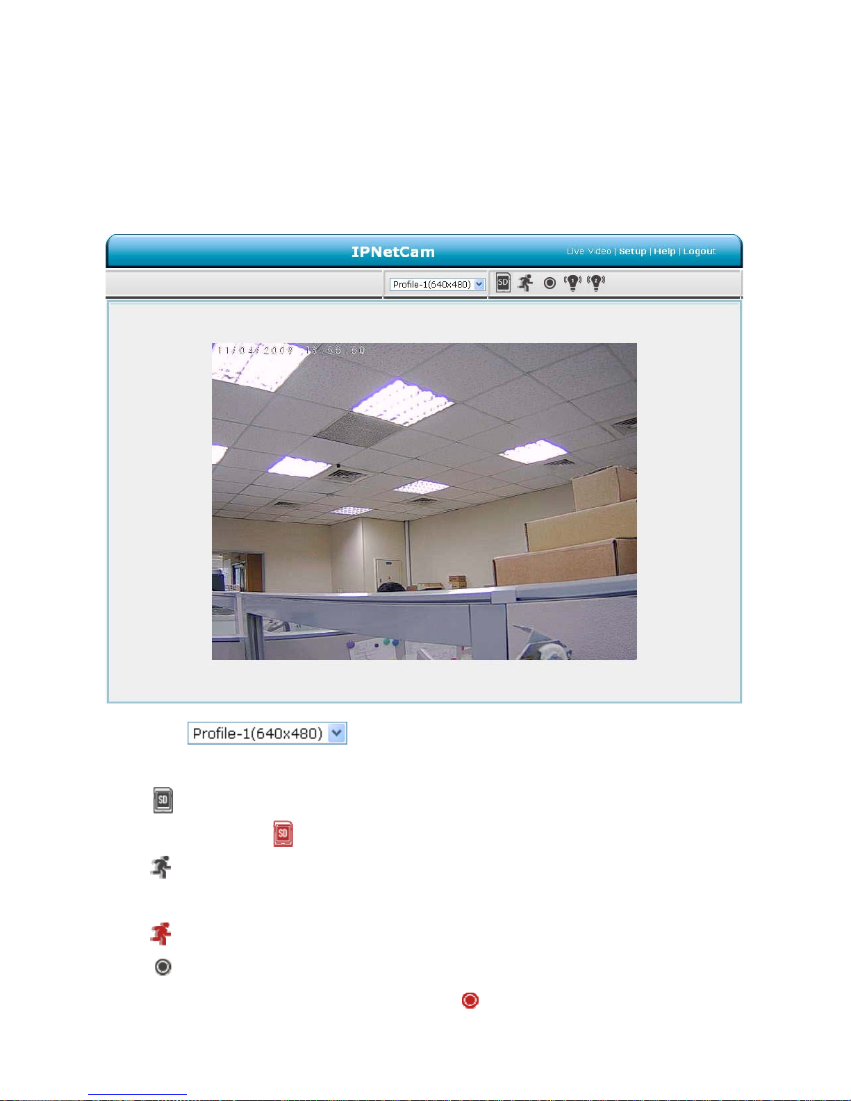
5.1.2 Live Video
The Live Video from the IP camera is displayed on the home page when your PC is online with
the IP camera. There are also additional settings provided on the home page. The AJAX (default)
and the ActiveX viewer types display different display formats on their home page.
The AJAX viewer type: Non-IE browsers support (for the JPEG mode only).
Click
to change the pairs of resolution and quality which you
already arranged in the “Audio and Video” setting page (for the JPEG mode).
SD card icon: Check if the SD card is inserted or not. When a SD card is inserted, the
icon becomes red
.
Motion-on icon: When there is a detection of motion, the icon will appear in the right
upper corner to warn the user.
When the motion detection is triggered, the icon will blink red
.
Status Recording on icon: The icon will appear on the upper right corner. When the
recording is triggered, the icon will become red
and record the images into the inserted
SD card.
Page 29

28
Alarm on-icon: When there is a detection of external devices such as a sensor, The
icon will appear on the upper right corner warn the user. When an alarm is triggered, the
icon will blink red
.
Alarm on-icon: When there is a detection of external devices such as a sensor, the icon
will appear on the upper right corner warn the user. When an alarm is triggered, the icon will
blink red
.
Page 30
29
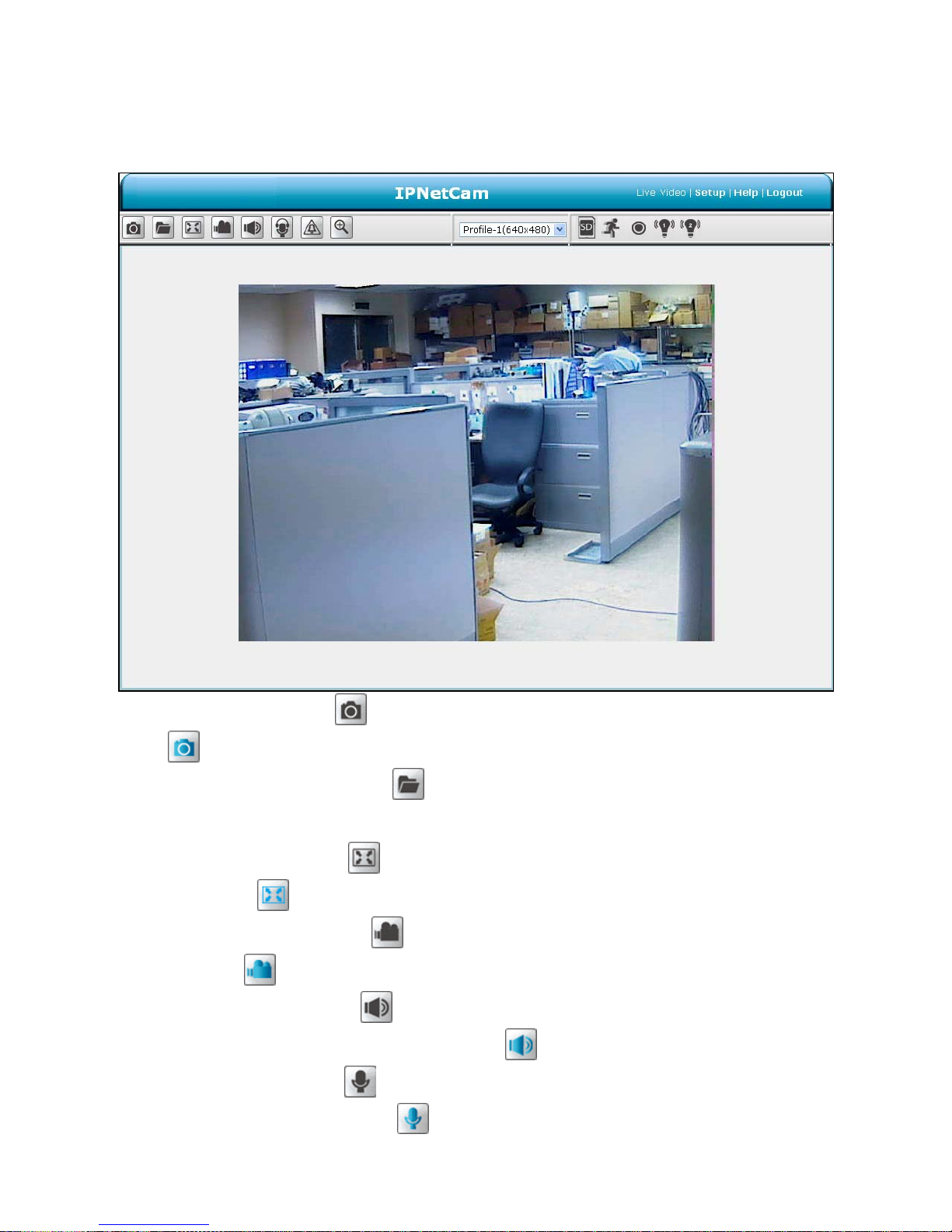
The ActiveX viewer type:
You can select from the available thumbnails for your option of taking a Snapshot, setting the
Storage Folder, selecting the Full Screen mode, Recording, Listen, Talk and Zoom.
Snapshot: Click on the button to take a snapshot. The icon will change to a blue color
while working effectively.
Set Storage Path: Click on the
button to set a storage folder for saving the snapshot
and the video clips.
Full Screen: Click on the
button to enter the full screen mode. The icon will change to
a blue color
while working effectively.
Record switch: Click on the
button to record a video clip. The icon will change to a
blue color
while working effectively.
Audio switch: Click on the
button to start/stop the audio-in function (listen/stop
listening). The icon will change to a blue color
while working effectively.
Talk switch: Click on the
button to start/stop audio out function (talk/stop talking). The
icon will change to a blue color
while working effectively.
Page 31

30
Digital output: Click on the button to start/stop digital output. The icon will change to a
blue color
while working effectively.
Zoom: Click on the
button to bring a popup “Zoom” window. The icon will change to a
blue color
while working effectively. Move the scrollbar "square" right or left to zoom
in or zoom out the Live View, and the red “Active Frame” will be narrowed down or
enlarged. You can drag the “Active Frame” to the desired position to see the detail of the
live image.
Live Video: Click to go back to the device’s homepage.
Setup: Click to proceed to the advanced settings.
Logout: Click to close the window.
Page 32

31
5.1.3 Setup
Click on the Setup button on the home page to proceed to the advanced settings.
5.1.3.1 Wizard
To
quickly configure your IP Camera, click Wizard on the top of the Setup pages.
This wizard will guide you through a step-by-step process to configure your new camera and
connect the camera to the Internet.
Click Next to continue.
Step 1:
The IP Box Camera default setting is DHCP Off. The default static IP is 192.168.1.168. You can set
an IP address for the IP Box Camera if the LAN unit isn’t connected to a DHCP server to build the
IP Box Camera working environment with a static IP address. Or you can turn the DHCP On to use
the DHCP protocol if the DHCP server is working in the LAN. The IP Box Camera will obtain an IP
address automatically from the DHCP server.
Page 33

32
If your Internet Service Provider has provided you with connection settings, or you wish to set a
static address within your home network, enter the accurate information for your static IP setting.
Click Next to continue.
Step 2:
If you are using PPPoE, select Enable and enter your user name and password, otherwise select
Disable and click Next to continue.
Step 3:
If you have a Dynamic DNS account and would like the camera to update your IP address
automatically, Select Enable and enter your host information.
Click Next to continue.
Page 34

33
Step 4:
Enter a name for your camera and click Next to continue.
Step5:
Configure the correct time to ensure that all events will be triggered, captured and scheduled at the
right time. Click Next to continue.
Step 6:
If you have selected DHCP, you will see a summary of your camera’s settings. Please note down
all this information as you will need it for accessing your camera within the network.
Click Apply to save your settings.
Page 35

34
5.1.3.2 Change Image Setting
Please follow the steps below to change the video setting through the network as necessary. A
preview of the image will be shown in the window of Live Video. Click Submit to activate and save
your changes.
The Image Setup setting page
1. Click on the Image button to enter the image-setting page.
Page 36

35
2. Adjust the “Viewer Type”. Click to choose the viewer type of the “AJAX” or “ActiveX” mode.
3. Adjust the ”Image Settings”, including “AGC”, “Exposure Time “, “Mirror”, “Flip”, “Power
Line”, ”White Balance”, “Brightness”, “Contrast”, “Saturation”, “Sharpness” and “WDR Level”
as necessary.
4. Adjust the ”Device Settings” including “Camera Name” and “Timestamp”.
Click “Enable OSD” to checkmark the box and activate the function.
Enter the "Timestamp Color" you have chosen.
Enter the "Timestamp Location" you have chosen.
Enter the "Timestamp Format" you have chosen.
5. Click on the Submit button to submit the new image setting.
Description of function keys:
AGC Automatic gain control is abbreviated AGC. Automatic gain control is a
feature where the amount of increase is adjusted automatically based upon
the strength of the incoming signal. Weaker signals receive more gain;
stronger signals receive less gain or none at all.
Exposure Time Exposure time is controlled in a camera by shutter speed and the
illumination level by the lens aperture.
Mirror: The mirror stores the images reflected by it so it can be used for
surveillance or to simply take your own picture.
Flip: To flip the camera’s lens 180 degrees.
Power Line Select 50 Hz or 60Hz that depends on your local electric utility
configuration.
White Balance White balance is the process of removing unnatural shades of color, so that
objects which appear white in reality are rendered white in the images.
Select your options from “Auto”, “Outdoor”, “Indoor” and “Fluorescent”.
Brightness: An adjustable setting to compensate for backlit scenes.
Contrast: The measurement for color intensity/strength.
Saturation: This setting controls the strength of colors from black and white to bold
colors.
Sharpness An adjustable setting to set the clarity of detail in the images.
WDR Level The Wide D ynamic Ra nge (WDR) function of a camera is intended to
Page 37

36
provide clear images even under back light circumstances. WDR enables
the capture and display of both bright areas and dark areas in the same
frame, in a way that there are details in both areas, i.e. bright areas are not
saturated, and dark areas are not too dark. Select your options of the level
between 0 and 8. 0 is the lowest level and 8 is the highest one.
Timestamp Color: Click to open the list of five color modes to choose from: “WHITE”,
“BLACK”, “GREEN”, “BLUE”, and “ORANGE”.
Timestamp Location: Click to open the list of four location modes to choose from: “UPPER
LEFT”, “UPPER RIGHT”, “BOTTOM LEFT”, and “BOTTOM RIGHT”.
Timestamp Format: Click to open the list of six format modes to choose from: “YYYY/MM/DD”,
“MM/DD/YYYY”, “DD/MM/YYYY”, “YYYY/MM/DD TITLE”, “MM/DD/YYYY
TITLE”, “DD/MM/YY TITLE”, “TITLE YYYY
/
MM/DD”, “TITLE
MM/DD/YYYY” and “TITLE DD/MM/YY”.
Submit: Click to set.
Page 38

37
The Audio and Video setting page
1. Click on the Audio and Video button to enter the Audio and video page to set the details of
the device. You may configure video profiles with different settings for your camera. Hence,
you may setup different profiles for your computer and mobile displays. In addition, you
may also configure your audio setup for your camera. Click Submit to activate and save
your changes.
2. Set the “Mode”, “Frame size”, “Maximum frame rate” and “Video quality” of the Video Profile
as necessary.
3. Set the details of the audio functions.
Page 39

38
4. Click on the Submit button to submit the new setting.
Description of function keys:
Mode: Choose the video format from “JPEG” or “MPEG4”. It can be either JPEG
or MPEG4. In JPEG mode, the video frames are independent. However,
MPEG4 consumes much less network bandwidth than JPEG.
Frame size: This option allows the user to choose the video resolution of the camera
between “1280x960”, “1280x720“, “640x480”, “320x240” and
“160x120”.
Maximum frame rate: Click on the drop-down list to choose the frame rates of “30FPS”,
“15FPS”, “7FPS”, “4FPS” and “1FPS”.
Video quality: Selects the image quality level of JPEG images captured from
“Excellent”, “Detailed”, “Medium”, “Good” and “Standard”.
Selects the image quality level of MPEG4 images captured from
“Constant bit” (8M, 6M, 4M, 2M, 1M, 512K, 256K, 200K, 128K and 64K)
or “Fixed Quality“ (Highest, High, Medium, Low and Lowest).
Intra Frame Period: In the MPEG4 mode, if there is little motion and most of the video
content does not change from frame to frame, the MPEG4 encoding
can compress the video by intra-frame way to keep the quality from
loss.
You can set the desired time period to use intra-frame compression.
Audio Settings: You can use the option to switch the external microphone on/off or
adjust the volume.
Encoding: Click on the drop-down list to choose the audio encoding of “G.711” and
“G.726”. G.726 offers quality nearly identical to G.711, but it uses only
half the bandwidth.
Page 40

39
The Privacy Mask setting page
Click on the Privacy Mask button to enter the Privacy Mask Area setting page. Mask 3 privacy
area(s) on video to specify up to the area(s) on the camera's image to be blocked/excluded from
recordings and snapshots.
1. Click the right mouse button on the video control to show the pop-menu.
2. Press the left mouse button, drag and drop to set the privacy area.
3. Privacy area can be enabled or disabled.
4. After you finish all privacy mask settings, click the Submit button.
Page 41

40
5.1.3.3 Change the Network Setting
Please follow the steps below to change the network setting through the network as necessary.
Set the network options and IP address.
1. Click on the Network button in the home page to enter the Network Setup page.
2. The accessible networks here are the “PPPoE”, “Port Detail”, ”Traffic”, “Dynamic DNS”,
“HTTPS” and ”Access List”.
3. Set the details of the “LAN Settings” for your local area network as necessary.
4. Click on the Submit button to submit the new network setting.
Description of function keys:
DHCP:
If you have a DHCP server running on your network and would
like a dynamic IP address to be updated to your camera
automatically.
DNS
(The Domain Name System) is an Internet service that
translates domain names into IP addresses (e.g., 192.168.0.20).
The address can be obtained from your ISP or network gateway.
Enable UPnP Presentation:
Enable this setting to allow your camera to be configured as an
UPnP device in your network.
Enable UPnP port forwarding:
Enable this setting to allow the camera to add port forwarding
entries into the router automatically on a UPnP capable network.
Page 42

41
Change the Network Setting — PPPoE.
The “Network” page has, on its upper left, the “PPPoE” icon. Please follow the steps below to change the
PPPoE setting through the network as necessary.
1. Click on the PPPoE button on the upper left menu to enter the “PPPoE Settings” page.
2. Active the “Enable” or “Disable” status of the PPPoE Settings function. Click your choices to
enable.
3. Enter the PPPoE “Username” and the PPPoE “Password”, then confirm the password again.
4. Click on the Submit button to submit the new setting.
NOTE: Please refer to section 5.1.3.8 (PPPoE & DDNS) for more details.
Description of function keys:
PPPoE Setting If you use the camera to connect directly to the Internet, you will need to
enter the username and password, which were given to you when you set
up your account with your Internet Service Provider. If the camera is
behind a router or a gateway, you do not need to configure this setting.
Username: Enter it in the given space.
Password: Enter it in the required space.
Page 43

42
Change the Network Setting — Port Detail.
The “Network” page has, on its upper left, the “Port Detail” icon. It allows you to specify and reserve the
ports for both the HTTP and RSTP streaming. Please follow the steps below to change the Port Detail
setting through the network as necessary.
1. Click on the Port Detail button on the upper left menu to enter the “Port Detail” page.
2. Enter the “HTTP port” and the “Access name for stream” for the MJPEG streams of the
HTTP.
3. Enter the “HTTP port”. The default value is 443.
4. Enter the “RSTP port” and the “Access name for stream” for the MJPEG or JPEG streams
of the RSTP.
5. Click on the Submit button to submit the new setting.
NOTE: If you want to use an RTSP player to access the IP camera, you have to use the following
RTSP URL command to request transmission of the streaming data.
Page 44

43
Description of function keys:
HTTP Port
HTTP ports allow you to connect to the camera via a standard web
browser. This port can be set to a number other than the default HTTP port
80. A corresponding port must be opened on the router. For example, if the
port is changed to 8080, users must type in the web browser
'http://192.168.0.100:8080' instead of 'http://192.168.0.100'.
HTTPS Port
HTTPS Port in a camera connects it with a PC via a secure web browser.
RTSP Port
The port number that you use for RTSP streaming to mobile devices, such
as mobile phones or PDAs. You may specify the address of a particular
stream. For instance, live1.sdp can be accessed at
rtsp://x.x.x.x/video1.sdp where the x.x.x.x represents the IP address of
your camera.
NOTE: Using a RSTP player to view the video streams
To view the MPEG4 streaming media by using RTSP players, you can use the players that
support RTSP streaming, such as Quick Time Player, Real Player, and so on.
(1) Launch the RTSP player.
(2) Choose “File”, and an “Open URL” dialog box will pop up.
(3) Enter an Internet URL to open. The address format is rtsp://<ip address>:<rtsp
port>/<RTSP streaming access name for stream1, stream2 or stream3>
(4) The live video will be displayed in your player.
Page 45

44
Change the Network Setting —Network Traffic.
The “Network” page has, on its upper left, the “Traffic” icon. Specifying the maximum download/upload
bandwidth for each socket is useful when connecting your device to a busy or heavily loaded network.
Please follow the steps below to change the setting through the network as necessary.
1. Click on the Traffic button on the upper left menu to enter the “Traffic” page.
2. Enter the “Maximum Upload Bandwidth” and the “Maximum Download Bandwidth”.
3. Click on the Submit button to submit the new setting.
Description of function keys:
Maximum Upload Bandwidth: Enter it in the given space from a range of 0 to 102400.
Maximum Download Bandwidth: Enter it in the required space from a range of 0 to 102400.
Submit: Click to set.
Page 46

45
Change the Network Setting — DDNS.
The DDNS (Dynamic Domain Name Server) will hold a DNS host name and synchronize the public IP
address of the modem when it has been modified. The user name and password are required when
using the DDNS service. The “Network” page has, on its upper left, the “DDNS” icon. Please follow the
steps below to change the DDNS setting through the network as necessary.
1. Click on the Dynamic DNS button on the upper left menu to enter the “Dynamic DNS” page.
2. Click “Enable DDNS” to checkmark the box and activate the function.
3. Fill in your dynamic “Server Address”, “Host Name”, “User Name”, “Password”, “Verify Password”,
“Timeout”, “IP Address” and “Email Address”.
4. Click on the Submit button to submit the new setting.
NOTE: Please refer to section 5.1.3.8 (PPPoE & DDNS) for more details.
Page 47

46
Description of function keys:
Enable DDNS Function: Checkmark to activate the function.
DNS (The Domain Name System) is an Internet service that translates domain
names into IP addresses (i.e. 192.168.0.20). The address can be
obtained from your ISP or network gateway.
Server Address: Select your Dynamic DNS provider from the pull down menu or enter the
server address manually.
Host Name: Enter the host name of the DDNS server.
User name: Enter your user name or e-mail used to connect to the DDNS
Password: Enter your password used to connect to the DDNS server.
Verify Passw ord Enter your password again to connect to the DDNS server.
Timeout: Enter the DNS Timeout values for registering the IP address.
Status: Indicate the connection status, automatically determined by the system.
Page 48

47
Change the Network Setting — HTTPS.
The “Network” page has, on its upper left, the “HTTPS” icon. Please follow the steps below to change the
HTTPS setting through the network as necessary.
1. Click on the HTTPS button on the upper left menu to enter the “HTTPS Setting” page.
2. Mark the “Enable HTTPS secure connection” to activate the function.
3. Click to select the “Create certificate method” from “Create self-signed certificate automatically”,
“Create self-signed certificate manually” and “Create certificate request and install”.
4. Click “Create” to save the create certificate settings.
5. The Certification Information will show below.
6. Click “CSR Property” to see the Certificate Signing Request information.
7. Click “Certificate Property” to see the Certificate information.
8. Click “Remove” to remove the created certificate.
9. Click on the Submit button to submit the new setting.
NOTE: The certificate cannot be removed while the HTTPS is still enabled. To remove the
certificate you must first uncheck Enable HTTPS secure connection.
Page 49

48
Methods of creating and installing the certificate:
1. Create self-signed certificate automatically
Before using HTTPS for communication with the IP camera, a Create self-signed certificate
automatically:
(1) Enable HTTPS secure connection.
(2) Select the “Create self-signed certificate automatically” option.
(3) Click the Create button.
(4) The new Certification Information will show in the third column on the HTTPS setting page.
(5) Click Home to return to the main page. Change the address from “http://” to “https://“ in the address
bar and press Enter on your keyboard. Some Security Alert dialogs will pop up. Click OK or Yes to
enable HTTPS.
2. Create self-signed certificate manually
(1) Enable HTTPS secure connection.
(2) Click “Create self-signed certificate manually” to open the Create certificate column.
(3) Click the Create button.
(4) The new Certification Information will show in the third column on the HTTPS setting page.
3. Create certificate request and install
(1) Enable HTTPS secure connection.
(2) Click “Create self-signed certificate automatically” to open the Create certificate column.
(3) Click the Create button.
(4) If you see an Information bar, click OK and click on the Information bar at the top of the page to
allow pop-ups.
(5) The pop-up windows will show a certificate request.
(6) Look for a trusted certificate authority that issues digital certificates. Enroll the IP camera. Wait for
the certificate authority to issue a SSL certificate; click “Browse...” to search for the issued
certificate, then click “Upload” on the Create certificate column.
(7) The new Certification Information will show in the third column on the HTTPS setting page.
Page 50

49
Change the Network Setting —Access List.
The “Network” page has, on its upper left, the “Access List” icon. Please follow the steps below to change
the Access List setting through the network as necessary.
1. Click on the Access List button on the upper left menu to enter the “Access List” page.
2. Fill in the “Start IP address”, “End IP address” and “Delete allow list” details of the “Allow List”. Press
the “Add” button to add or press “Delete” to erase it.
3. Fill in the “Start IP address”, “End IP address” and “Delete deny list” details of the “Deny List”. Press
the “Add” button to add or press “Delete” to erase it.
4. Click on the Submit button to submit the new setting.
Description of function keys:
Allow List:
Start IP Address The starting IP Address of the devices (such as a computer) which have
permission to access the video of the camera.
End IP Address The ending IP Address of the devices (such as a computer) which have
permission to access the video of the camera.
Delete Allow List Remove the customized setting from the Permission List.
Page 51

50
Deny List:
Start IP Address The starting IP Address of the devices (such as a computer) which don’t
have permission to access the video of the camera.
End IP Address The ending IP Address of the devices (such as a computer) which don’t
have permission to access the video of the camera.
Delete Deny List Remove the customized setting from the Permission List.
Page 52

51
5.1.3.4 Change the System Setting
Please follow the steps below to change the date and time of the system setting through the network as
necessary.
Set the Time and Date of the system
1. Click on the System button to enter the “Time And Date” page (default).
From this section, you may
automatically or manually configure, update and maintain the internal system clock for your camera.
2. To set the Time Configuration, please select your time zone from the drop-down menu. Select this to
enable the daylight saving time. Then Select ”Auto Daylight Saving” or “Set date and time manually”.
3. To set the Automatic Time Configuration, please checkmark “Synchronize with NTP Server” and
enter the address of the NTP Server.
4. To set the Date and Time Manually, please checkmark “Set date and time manually”. Press “Copy
Your Computer’s Time Settings” as necessary to synchronize the time information from your PC or
just manually set the date and time from the drop-down lists.
5. Click on the Submit button to submit the new Date and Time settings.
Page 53

52
Description of function keys:
Time Zone: Select your time zone from the drop-down menu.
Enable Daylight Saving: Select this to enable the daylight saving time.
Auto Daylight Saving: Select this option so that your camera will configure the
Daylight Saving setting automatically.
Set date and time manually: Select this option so that you may configure the Daylight
Saving date and time manually.
Offset: Sets the amount of time to be added or removed when
Daylight Saving is enabled.
Synchronize with NTP server: Enable this feature to obtain time configuration
automatically from the NTP server.
NTP Server: The Network Time Protocol (NTP) synchronizes the device
with an Internet time server. Choose the one that is closest
to your location.
Set the date and time manually: This option allows you to set the time and date manually.
Copy Your Computer’s Time Settings: This will synchronize the time information from your PC.
NOTE: If there are any conflicts between the range of the Allow List and the range of the Deny
List, the Access List within the range of the Deny List has the higher priority over the
range of the Allow List.
For example, the range of the Allow List is set from 1.1.1.0 to 192.255.255.255 and the
range of the Deny List is set from 1.1.1.0 to 170.255.255.255. Only users with IPs located
between 171.0.0.0 and 192.255.255.255 can access the IP camera.
Page 54

53
Change the System Setting — Digital Input &Output.
You may enable the Digital Input (D/I) and Digital Output (D/O) feature and configure the source of
events for your camera.
1. Click on the DI and DO button on the left side of the “System” page to enter the “DI and DO” page.
2. Select the active state of the Digital Input 1 from the drop-down list.
3. Select the active state of the Digital Output 1 from the drop-down list.
4. Click to set the LED “On” or “Off’.
5. Click to set the Video Output “On” or “Off’. Set to on when the camera connects with an external
device.
6. Click on the Submit button to submit the new user’s setting.
Page 55

54
Change the System Setting — ICR.
Please follow the steps below to change the IR cut function through the network as necessary.
1. Click on the ICR button on the left side of the “System” page to enter the “ICR” page.
2. For the “IR-Cut Removable filter trigger condition”, mark your options from “Automatic”, “Day Mode”,
“Night Mode” or “Schedule”. Click your choices to enable.
3. Mark the IR light power from “Off”, “On”, “Sync, with ICR” or “Schedule”. Click your choices to
enable.
4. Click on the Submit button to submit the new user’s setting.
Description of function keys:
Automatic The Day/Night mode is set automatically. It is normally set in the Day
mode and changes to the Night mode in a dark place.
Day mode The Day mode disables the IR Cut Filter.
Night mode The Night mode enables the IR Cut Filter.
Schedule mode Set the Day/Night mode using the schedule. Fill in the time so the
Day/Night mode is normally set to Day mode and it enters the Day mode
at the start time and returns to the Night mode at the end time.
Page 56

55
Change the System Setting — RS485 Setting.
You may configure the RS-485 settings or communication specifications (baud rate, data bit, stop bit,
and parity bit) for your camera. The RS-485 is a serial communication method for computers and
devices. For your camera, the RS-485 is used to control a PAN/TILT device, such as an external
camera enclosure, to perform the PAN and TILT movement. Click on the RS485 Setting button on the
left side of the “System” page to enter the “RS485 Setting” page.
Note: Checkmark “Support PAN-TILT” and a RS-485 control panel will appear on the left side of
the Live View page.
Description of function keys:
Support PAN-TILT:
When enabling Support PAN-TILT, a control panel will be displayed on
the Live Video page allowing control for an external camera enclosure
through the RS-485.
Protocol:
Select one protocol type from the pull-down menu.
ID:
Choose an ID between 1 and 25 5. This ID is the identifier for each
RS-485 device.
Page 57

56
Baud Rate:
Choose between 2400 and 115200 bps. This is a speed measurement
for communication between a transmitter and receiver, indicating the
number of bit transfers per second. A higher baud rate will reduce the
distance of the two devices (transmitter and receiver).
Data Bits:
Either 7 or 8. It is a measurement of the actual data bits in a
transmission. By default, the value is 8.
Parity Bit:
Choose from No, Even, and Odd. This is a simple form of error checking
used in serial communication and you may use no parity. For even and
odd parities, the serial port sets the parity bit (the last bit after the data
bits) to a value to ensure that the transmission has an even or odd
number of logic-high bits.
For example, if the data is 011, for even parity, the parity bit is 0 to keep
the number of logic-high bits even. If the parity is odd, the parity bit is 1,
resulting in 3 logic-high bits.
Stop Bit:
Either 1 or 2. It is used to signal the end of communication for a single
packet. The more bits used for stop bits, the greater the lenience in
synchronizing the different clocks but the slower the data transmission
rate. In default mode, the value is 1.
Page 58

57
Change the System Setting — Users.
You may modify the name and administrator’s password of your camera, as well as add and manage the
user accounts for accessing the camera. You may also use this section to create the unique name and
configure the OSD setting for your camera. Please follow the steps below to change/add the users’
authority through the network as necessary.
1. Click on the Users button on the left side of the “System” page to enter the “Users” page.
2. Add, modify or delete any user’s data if necessary.
3. Click the Submit button to submit the new user’s settings.
4. Click the Home button to return to the home page.
Description of function keys:
User List: The list shows the registered user(s) and the corresponding authority.
Delete: Deletes a selected user.
Name: Enter the user’s name, which will be added or modified.
Password: Enter the new password of the user’s name above.
Confirm: Type in the password again for verification.
Authority: Choose an authority option of the user’s name from: Admin, Operator, and
Viewer.
Submit: Click to submit the new setting to the IP camera.
Page 59

58
Change the System Setting — Maintenance.
Please follow the steps below to change the system setting through the network as necessary.
Click on the Maintenance button on the left side of the “Date and Time” page to enter the “System”
page.
Description of function keys:
Save Configuration: Click on “Save Configuration” to save the configuration files to the local
hard drive.
Load Configuration: Browse and click on the “Load Configuration” to load the configuration
files to the local hard drive.
Restore Factory Defaults: Click on “Restore Factory Defaults” to restore the factory defaults. Yo u
may browse and load the configuration file. This option will restore the
pre-configured or saved settings
Reboot Device: Click on “Reboot Device” to reboot the device. This option will restart
the camera.
Page 60

59
Change the System Setting — Update Firmware.
Please follow the steps below to update the firmware through the network as necessary.
1. Click on the Firmware Upgrade button on the left side of the “Date and Time” page to enter the
“Firmware Upgrade” page.
2. Click on the “Browse…” button to select the UPDATE.BIN file which was copied into your
computer.
3. Click on the “Upload” button.
NOTE: DO NOT power off the IP camera while updating firmware.
NOTE: Don’t interrupt the process while the unit is updating itself.
NOTE: Please make sure that the UPDATE.BIN file is appropriate to the model of the unit.
Updating with the wrong UPDATE.BIN file may cause physical damage to the device.
NOTE: The Temporary Internet Files (or cache) folder contains Web page content that is stored
in your hard disk for quick viewing. We suggest deleting the Temporary Internet Files
immediately after updating the firmware. To delete the files in the Temporary Internet
Files folder, follow these steps:
Page 61

60
1. Quit Internet Explorer and quit any instances of Windows Explorer.
2. Click Start, click Control Panel, and then double-click Internet Options.
3. On the General tab, click Delete Files under Temporary Internet Files.
4.
Select the Delete all offline content check box in the Delete Files dialog box, and then click
OK.
5. Click OK.
Page 62

61
5.1.3.5 Change the Application Setting
Please follow the steps below to change the application setting through the network as necessary.
Change the Application Setting —Language Setting.
Please follow the steps below to change the Language setting via the network as necessary.
1. Click on the Language button on the left side to enter the “Language Setting” page.
You have an option as to which language to use. The default is “English”
2. Choose your selected language and click "Submit" to set it.
Page 63

62
Change the Application Setting —Motion Detection.
Please follow the steps below to enable changes in the motion detection function of the alarm
through the network as necessary.
Set the motion detection:
1. Click on the Motion Detection button on the left side of the Alarm to enter the “Motion
Detection” page.
2. Click and drag the mouse across a targeted zone to draw a red rectangle on the image
(coordinates provided below).
NOTE: You can set more than one targeted zone depending on your requirement.
3. Enables / disables the motion detection function.
4. Set up the signal level.
5. Click on the Submit button to submit the new setting of the recording.
6. Click on the Home button to return to the home page.
Description of function keys:
Sensitivity: The sensitivity bar allows you to specify how much movement is required to
trigger the motion detection.
Percentage: Adjusting the percentage allows you to set a requirement on how much of the
motion window must be filled by movement. Example: If you set this to 50%,
then the selected window must be half filled by a moving object before it
triggers motion detection.
Page 64

63
Change the Application Setting —Event.
In this section, you can configure and schedule the recording setting for your IP camera.
Click on “Add” to enter the setting pages of the Server, Media, Event and Recording to make the
advanced settings. Or click on “Delete” to erase the settings.
The Event Setup page includes 4 different sections: Server, Media, Event and Recording.
1. To add a new item - "event, server or media," click Add.
2. To delete the selected item from the pull-down menu of event, server or media, click
Delete.
3. Click on the item name to enter the window for modifying.
NOTE: You can add up to five servers, five media fields, three event schedules, and two
recording schedules.
Page 65

64
Server:
Click on the Add button in the Server column to enter the “Server” setting page.
1. Enter the Server name, the unique name for a server. There are four kinds of servers
supported. They are email server, FTP server, HTTP server and network storage.
2. Set the details of the Email. "Sender email address": The email address of the sender.
"Recipient email address": The email address of the recipient.
3. Set the details of the FTP. "Remote folder name": An authorized folder on the external
FTP server. The string must conform to that of the external FTP server. Some FTP servers
cannot accept a preceding slash symbol before the path without virtual path mapping. Refer
Page 66

65
to the instructions for the external FTP server for details. The folder privilege must be open
for uploading. "Passive Mode": Check it to enable the passive mode in transmission.
4. Set the details of the Network storage. Only one network storage is supported. "Network
storage location": The path to upload the media. "Workgroup": The workgroup for
network storage.
5. Click on the SD card to activate the function. Use the SD card for recording media.
6. Click on “Submit” to save or click on “Don’t Submit” to go back to the Event main page.
Server settings:
(1) Click Add under the Sever column on Event Settings page to open the Server setting
page. On this page, you can specify where the notification has been sent when a trigger is
activated. A total of 5 server settings can be configured.
NOTE: The maximum server settings amount is five, however, you can set the
Network storage or the SD card for only one.
(2) Enter the Server Name for the server setting.
(3) Select the Server Type. There are four choices of server types available: Email, FTP,
Network storage and SD card. Select one of the server types.
Email: Select to send the media files via the email when a trigger is activated.
(a) Sender email address: Enter the email address of the sender.
(b) Recipient email address: Enter the email address of the recipient.
(c) Server address: Enter the domain or IP address of the email server.
(d) User name: Enter the user name of the email account if necessary.
(e) Password: Enter the password of the email account if necessary.
(f) Port: The default email server port is 25. You can also manually set another
port.
(g) To verify if the email setting is correctly configured, click the Test button. The
result will be shown in above this setting page (TEST OK or TEST ERROR).
(h) Click Submit to activate the setting.
Page 67

66
FTP: Select to send the media files to an FTP server when a trigger is activated.
(a) Server address: Enter the domain or IP address of the FTP server.
(b) Port: The default FTP server port is 21. It can also be assigned to another
port number.
(c) User name: Enter the login name of the FTP account.
(d) Password: Enter the password of the FTP account.
(e) Remote folder name: Enter the folder where the media file will be placed. If
the folder name does not exit, the IP camera will create one on the FTP
server.
(f) Passive mode: Most firewalls do not accept new connections initiated from
external requests. If the FTP server supports passive mode, select this
option to enable passive mode FTP and allow data transmission to pass
through the firewall.
(g) To verify if the FTP setting is correctly configured, click the Test button. The
result will be shown in above this setting page (TEST OK or TEST ERROR).
(h) Click Submit to activate the setting.
Network storage: Select to send the media files to a network storage location
when a trigger is activated. Please fill in the information for your server.
(a) Network storage location: Enter the network storage path (\\ server name or
IP address\ folder name).
(b) Workgroup: Enter the workgroup name for the network storage server.
(c) User name: Enter the user name for the server.
(d) Password: Enter the password for the server.
(e) Primary WINS server:
(f) To verify if the storage setting is correctly configured, click the Test button.
The result will be shown in above this setting page (TEST OK or TEST
ERROR).
(g) Click Submit to activate the setting.
Page 68

67
SD card: Select to send the media files to an SD card when a trigger is activated.
(a) Insert your SD card first.
(b) To verify if the storage setting is correctly configured, click the Test button.
The result will be shown in above this setting page (TEST OK or TEST
ERROR).
(c) Click Submit to activate the setting.
(4) When completed, click Submit to enable the settings to exit this page. The new server
settings will appear on the Event Settings page.
NOTE: To remove a server setting from the list (Application> Event>), select a server
name from the drop-down list and click Delete.
Note that only when the server setting is not being applied to an event setting
(Application> Event> Event> The “Action” option) can it be deleted or the camera
won’t take any action when a trigger is activated.
Page 69

68
Media:
Click on the Add button in the Media column to enter the “Media” setting page.
1. Enter the Media name, the unique name for media. There are three kinds of media:
snapshot, video clip and system log.
2. Set the details of the Snapshot.
"Source": Select the video source.
"Send Pre-event images": The number of pre-event images.
"Send Post-event images": The number of post-event images.
"File name prefix": The prefix name will be added on the file name of the snapshot images.
"Add date and time suffix to file name": Check it to add timing information as file name
suffix.
3. Set the details of the Video Clip.
"Source": Select the video source.
"Pre-event recording": The interval of pre-event recording in seconds. There are two
Page 70

69
limitations for video clip file.
"Maximum duration": The maximum recording file duration in seconds.
"Maximum file size": The maximum file size would be generated.
4. Click on the System log to activate the function.
5. Click on “Submit” to save, or click on “Don’t Submit” to go back to the Event main page.
Media settings:
1. Click Add under the Media column on Event Settings page to open the Media setting
page. On this page, you can specify the type of media that will be sent when a trigger is
activated. A total of 5 media settings can be configured.
2. Enter the Media Name for the media setting.
3. Select the Media Type. There are three choices of media types available: Snapshot,
Video Clip and System log. Select one of the media types.
Snapshot: Select to send snapshots when a trigger is activated.
(a) Source: Select to take snapshots from the video profile.
(b) Send pre-event image(s) [0~4]: The IP camera has a buffer area; it
temporarily holds data up to a certain limit. Enter a number to decide how
many images to capture before a trigger is activated. Up to 4 images can be
generated.
(c) Send post-event image(s) [0~7]: Enter a number to decide how many
images to capture after a trigger is activated. Up to 7 images can be
generated.
NOTE: For example, if both the Send pre-event images and Send
post-event images are set to 4, a total of 8 images are
generated after a trigger is activated.
(d) File Name Prefix: Enter the text that will be appended to the front of the file
name.
For example, the file name will be in this form:
Page 71

70
Snap_20090101_122030
The prefix file name
Date and time suffix
The format is: YYYYMMDD_HHMMSS
(e) Add date and time suffix to file name: Select the option to add the date/ time
suffix to the file name.
(f) Click Submit to activate the setting.
Video Clip: Select to send video clips when a trigger is activated.
(a) Source: Select to record video clips from the video profile.
(b) Pre-event recording: The IP camera has a buffer area; it temporarily holds
data up to a certain limit. Enter a number to decide the duration of recording
before a trigger is activated. Up to 4 seconds can be set.
(c) Maximum duration: Specify the maximum recording duration in seconds. Up
to 100 seconds can be set.
NOTE: For example, if pre-event recording is set to 4 seconds and the
maximum duration is set to 10 seconds, the IP camera
continues to record for another 5 seconds after a trigger is
activated.
1 sec. 2 sec. 3 sec. 4 sec. 6 sec. 7 sec. 8 sec. 9 sec. 10sec.5 sec.
Pre-event Recording
Continues to record
Trigger Activation
Maximum recording duration
(d) Maximum file size: Specify the maximum file size allowed.
(e) File Name Prefix: Enter the text that will be appended to the front of the file
name.
(f) Click Submit to activate the setting.
Page 72

71
System log: Select to send a system log when a trigger is activated. Click Submit
to activate the setting.
4. When completed, click Submit to enable the settings to exit this page. The new media
settings will appear on the Event Settings page.
NOTE: To remove a media setting from the list (Application> Event>), select a media
name from the drop-down list and click Delete.
Note that only when the media setting is not being applied to an event setting
(Application> Event> Event> The “Attached media” item) can it be deleted or you
can’t get the images/ logs when a trigger is activated.
Page 73

72
Event:
Click on the Add button in the Event column to enter the “Event” setting page.
1. Enter the Event name. Checkmark the “Enable this event” box and activate the function.
Then set the Priority and the Source from the drop-down list.
"Priority": The event with higher priority will be executed first.
2. Select the event trigger mode.
"Video motion detection": Select the windows which need to be monitored.
"Periodic": The event is triggered in specified intervals. The unit of trigger interval is a
minute.
"Digital input": The event is triggered when the DI status is changed by an external device.
"System boot": The event is triggered when the system boots up.
3. Set the recording schedule time.
4. Set the Trigger D/O of activating the action. Check it to trigger digital output for specific
Page 74

73
seconds when an event is triggered.
5. Click on “Submit” to save or click on “Don’t Submit” to go back to the Event main page.
Event settings:
(1) Click Add under the Event column on Event Settings page to open the Event setting page.
On this page, you can arrange three parts –Trigger, Event Schedule, and Action to set an
event. A total of 3 event settings can be configured.
(2) Enter the Event Name for the event setting.
(3) Select “Enable this event” option to enable the event setting.
(4) Set the event priority from: “normal”, “high” and “highest”. Events with a higher priority will
be executed first.
(5) Enter the duration in seconds to pause motion detection after a motion is detected (for the
trigger types - motion detection and digital input – use only).
(6) An event is an action initiated by a user-defined trigger source; it is the causal
arrangement of the following three parts: Trigger, Event Schedule, and Action. Set the
event details of each part.
Trigger: This option defines when to trigger the IP camera. The trigger source can
be configured to use the IP camera’s built-in motion detection mechanism, periodic,
external digital input devices or system boot. There are several choices of trigger
sources as shown below.
(a) Video motion detection: This option makes use of the built-in motion
detection mechanism as a trigger source. To enable this function, you need
to configure a motion detection windows first.
NOTE: For example, when the event status is on, once an event is triggered
by motion detection, the IP Camera will automatically send
snapshots, video clips or System log via the server type as your
settings.
(b) Periodic: This option allows the IP camera to trigger periodically for every
other defined minute(s). UP to 99999 minutes.
Page 75

74
(c) Digital input: This option allows the IP camera to use an external digital input
device or sensor as a trigger source. Depending on your application, there
are many choices of digital input devices on the market which helps to
detect changes in temperature, vibration, sound, and light, etc.
(d) System boot: This option triggers the IP camera when the power to the IP
camera is disconnected.
Event Schedule: Specify the period for the event.
(a) Select the days of the week.
(b) Set the recording schedule in the 24-hour time format.
Action: Define the actions to be performed by the IP camera when a trigger is
activated.
(a) Trigger D/O for ~ seconds: Select this option to turn on the external digital
output device when a trigger is activated. Specify the length of the trigger
interval in the text box.
(b) If you want to set an event with recorded video or snapshots, it is necessary
to configure the server and media settings first so that the IP camera will
know what action to take (such as which server to send the media files to)
when a trigger is activated.
Checkmark the one of the Server Names which you have set already, then
select the Attached media (the media name) from the drop-down list.
(7) When completed, click Submit to enable the settings to exit this page. The new event
settings will appear on the Event Settings page.
NOTE: The new event settings / server settings / media settings will appear in the event
drop-down list on the “Application> Event>” page.
Page 76

75
Recording:
Click on the Add button in the Recording column to enter the “Recording” setting page.
1. Enter the Recording entry name. Checkmark the “Enable this recording” box and activate
the function. Enable this option if you want to upload the recording to a shared folder in the
network. Then set the Priority and the Source from the drop-down list.
2. Set the recording schedule time.
Select the day(s) according to when you want the camera
to make a video clip.
3. Set the details of the recorded file.
"Always": This enables the camera to make video clips continuously.
"From": The time range specified for the video clip.
4. Click on “ Save Settings” to save or click on “Don’t Submit” to go back to the Event main
page.
Page 77

76
Record settings:
(1) Click Add under the Record column on Event Settings page to open the Record setting
page. In this page, you can define the recording source, recording schedule and
recording capacity. A total of 2 recording settings can be configured.
(2) Enter the Record entry name for the event setting.
(3) Select “Enable this recording” option to enable the recording setting.
(4) Select the recording priority from: “normal”, “high” and “highest”. Recording with a higher
priority will be executed first.
(5) Select the recording source from the drop-down list (profiles).
(6) Specify the recording schedule and the recording settings.
Recording Schedule:
(a) Select the days of the week.
(b) Set the recording schedule in the 24-hour time format.
Recording Settings:
(a) Destination: You can select the SD card or SAMBA (Network storage) that
was set up for the recorded video files.
(b) Total cycling recording size: When the maximum capacity is reached the
value you set, the oldest file will be overwritten by the latest one. The
reserved amount is reserved for cyclic recording to prevent malfunction.
The limited value is 1000~200000000 Kbytes.
(c) Size of each file for recording: Set the maximum file size of each recording
video files.
(d) File Name Prefix: Enter the text that will be appended to the front of the file
name.
(7) When completed, click Submit to enable the settings to exit this page. The new media
settings will appear on the Event Settings page.
Page 78

77
5.1.3.6 Change the SD card Setting
Please follow the steps below to change the SD card setting through the network as necessary.
Change the SD card Setting.
Please follow the steps below to change the setting via the network as necessary.
1. Click on the “storage” button at the top of the Setup page to enter the “SD Card” screen.
2. The SD Card page contains two image modes, the Video and the Picture.
3. Click “Video” or “ Picture” to enter its sub year-month folder.
4. Click to enter its sub date folder.
5. Click the desired file to display the images therein.
6. Each file can be deleted by checking and pressing the OK button.
Page 79

78
5.1.3.7 Device information
The device information.
This page displays all the information about your device and network connection.
Click on the “Device info” button of the Status page to enter the “Device info” screen.
Page 80

79
The device information.
This page displays the log information of your camera.
1. Click on the “Device info” button of the Status page to enter the “Device info” screen.
2. Click on the “Clear “ to erase all of the logs. You may also download the information by
clicking “Download”.
Page 81

80
5.1.3.8 PPPoE & DDNS
Using the PPPoE
1. Install the XDSL software (obtained from your ISP dealer) in your PC.
2. Search your IP camera's IP address: you can connect the IP camera and the Video monitor.
The monitor screen will show the IP address on its right side.
3. Turn off the DHCP function (of the IP camera) if it is “ON”.
Note: Use the IE browser to go to the Network Setting page to note the check box at the top
of the page. If the box has a tick mark, click it to “OFF".
4. Installing an IP address in your PC or notebook.
Desktop → Move the mouse focus to the Network neighborhood and click the right key of the
mouse → Choose the properties → Choose your local connection → Choose the properties
and select the configuration → Select the TCP / IP → Choose the properties → Enter the IP
address in a four-part formula, for example “192. 168. 1.101” (the first three parts must be
identical to the above numbers, only the last part can be changed to your own number, which
must never exceed 255) → Click on the mask and the mask input, namely “255. 255. 255. 0”
(a fixed formula) → Click “OK” → Click “OK”.
5. Desktop → Choose IE browser → Enter the IP camera IP address in the URL (check step #
2 above) → Enter → IP camera images will appear.
PPPoE Settings
1. Enter the IP camera home page → Choose the network → Enter “User Name: admin” and
“Password: 9999” → Click “OK’.
2. Choose PPPoE → PPPoE mode: Select “ON” → Enter “Account” → Enter “Password” →
Submit → Unplug the power connection.
3. Plug in the IP camera and it will receive an IP address from the ISP dealer (this IP address
is dynamic --- every time you unplug and plug in again you’ll get a new IP address).
Page 82

81
Test: Go to the Internet.
1. Set your PC to enter the Internet.
2. Desktop → IE browser → Enter the IP camera IP address (the same address as in the
PPPoE settings and step 3 above) → You can see the IP camera images.
DDNS settings
1. Check your IP camera’s IP address (monitor) → open your IE browser → Use the address
to connect to the IP camera or view the images → Choose the network → Enter “User
name : admin” and “Password : 9999” → Click “OK” .
2. Choose the “DDNS” → Click “Enable DDNS” → Enter the “DDNS host name”, for example
“abc123. homeip.net” → Enter “DDNS Account”, for example “abc123” → Enter the “DNS
Password”, for example “7777” → Submit → The settings are now complete → Close the IE
browser.
3. Open the IE browser again → Enter the Website address you just applied for, such as
“abc123.homeip.net” → You can look at your IP camera images right away. The procedure
is complete.
Note: These settings are only for your ADSL Dynamic IP configuration. If your
configuration is fixed (true IP), you don’t need to proceed with the PPPoE and DDNS
settings. The DDNS is just for your convenience.
Page 83

82
5.2 The IP Camera CMS (Central Management System)
This section provides instructions for installing and using the Ce ntral Ma nagement S ystem
( CMS ) which is included with the IP Camera. The programs can be operated by a selected PC
equipped with the following requirements.
System Requirements
Intel Pentium 1.5 GHz processor or higher (2.8 GHz or higher recommended).
128-MB RAM at least (256-MB or higher recommended).
Windows XP only.
4 MB VGA card capable of 24-bit true color display.
100 MB free hard-disk space for software installation.
10/100 Base-TX network for LAN operation.
The Microsoft Internet Explorer 6.
In the multi-channel recording mode, the HD data transfer rates must be 66MB or above (100MB
or higher recommended).
5.2.1 Introduction to the CMS
The CMS allow
s
you to access many units of the IP Camera from a remote desktop or a
laptop in a TCP/IP networking environment. It can perform the following functions.
Views live images in a smooth sequential flow from an IP camera.
Stores, searches, and reviews recorded video from a PC or an SD card quickly.
Changes manual record, event record, and schedule record settings easily.
Before you view images from a desktop, you need to have your IP Camera networked by
obtaining a 10/100 base-TX Ethernet data cable (Standard RJ-45) to connect the IP Camera
to your LAN/WAN. Now enter the main menu to set the IP address.
Page 84

83
5.2.2 Install the CMS in your PC
Install the CMS from the supported CD-R.
1. Exit all applications currently running in the selected PC.
2. Insert the supported CD in the CD-ROM drive. The program will execute the installation
automatically. Follow the on-screen instructions to proceed with the rest of the installation
procedure as they appear.
NOTE: The program will update the .NET Framework to version 2.0 automatically. Please
click “Next” to start and finish the setup process.
3. Select a language of the installing process from the drop-down list in the “Installer
Language” window.
4. After the installation is complete, pop up the START menu from your computer, and point
to Programs / CCTV CMS / CCTV CMS to open up the program selection page as shown
below. Click on the CCTV CMS tag to start the CMS program.
Install the CMS for the ZIP file.
1. Save the ZIP file to your PC and extract the file to a designated directory.
2. Open the extracted folder. The folder contains one file.
3. Click the setup icon to execute the installation and then follow the on-screen instructions
to proceed with the rest of the installation procedure.
4. After the installation is complete, click the START menu from your computer, and point to
Programs / CCTV CMS to start the CMS program.
NOTE: Please make sure the TCP/IP communication software has been properly set and
configured i n your c omputer. To check your TCP/IP se ttings, pleas e refer to
section 4.5 (the TCP/IP configuration settings).
Page 85

84
5.2.3 Login the IP Camera software
Once the CMS is executed, a Login prompter will appear. You must enter the default user
name: admin, and the password: 9999 in the respective spaces (and confirm the password
again the first time you log in). Click the “OK” button and enter the console page of the CMS:
both the user name and password must be entered correctly. Click the “Cancel” button and
exit the login of the CMS.
View the IP Camera video from a remote PC
Follow the instructions below to use the CMS to browse an IP Camera video from a remote
location. Upon entering the CMS, a connection box will appear as follows.
1. Press the
(Add Device) button on the Device Management page.
Page 86

85
2. Add a channel from the Add Device page.
3. (1) Click the A uto Search button at the bottom of the "Add D evice " page to
discover the connection of the IP Camera-type device in the LAN. Instantly the
"Search De vice" page will appear. Click the device of your choice and click
"Add" at the bottom of the page to access the "Add Device " page again.
(2) This page provides the IP Address and the HTTP Port. After typing the
Device Tile, Username, Password and selecting the share device function or the
permissions function, please click the "Add " button to establish the connection
between the device and the computer.
4. Click the device title to begin viewing images with this camera from the device
list.
NOTE: To add more connections or units to the IP Camera, please repeat the above
instructions.
NOTE: Please click the Test Connection icon to test the connecting situation and
preview the video of the IP Camera.
Page 87

86
5.2.4 Operation
5.2.4.1 Device Management
Once the connection has been established, click the
button to
enter the Device Management window ( see the sample screen below.) On the left side of the
window is the connected device that has been arranged when you established the
connection.
1
Add device:
Add a new device. For more details please refer to section 5.2.3.
Modify device:
Modify the added device. Please select a device, then click this button to edit
the device.
Delete device:
Delete the added device.
Device Setting:
For additional settings of each channel, please select the device title on the
left side and click the setting button to enter the setting pages of the device.
Schedule Setting:
For the further settings of each channel, please select the device title on the
left side and click the Schedule button to enter the schedule setting pages
of the device.
2
List of devices:
You can click the title of the device and use the icons above the list to change the device
settings.
3
Display area:
Click the title of the device, and you will see the live image in this area.
Page 88

87
NOTE:
The Device Setting page:
For additional settings for each channel, please select the device title on the left side and
click the setting button to enter the setting pages of the device. Click the “Setting” button to
bring up the device-setting pages.
The method of operation is the same as with the Microsoft Internet Explorer setting pages
(please refer to section 5.1 for more details).
Page 89

88
NOTE:
The Schedule Setting page:
Click the
icon to enter the Schedule setting page.
1
The setting area:
Sets the recording day from the drop-down list.
Note: After the setting of the starting and ending time is done, select
“Daily” to add the same time schedule from Sunday to Saturday.
Page 90

89
Sets the starting time of recording from the drop-down list.
Sets the ending time of recording from the drop-down list.
Clicks the icon to enable the just added schedule.
Clicks the icon to disable the selected schedule.
2
The working area:
(1)
Click the working area directly to add a new schedule as you wish.
(2) The functioning schedule bar is colored orange, and the non-functioning schedule
bar(s) is colored pink. You can just click the right button of the mouse on the functioning
schedule bar ( in orange color) to cancel it.
(3) To enlarge the display size of the working area, please click the left button of the mouse
on the numerical bar (
…) ; on the other hand, please click the right button
to narrow it.
Note: The largest column length is 4 times the default size of the working area.
3
The schedule bar:
(1) Click and drag the left and right edges of the schedule bar to adjust the starting and
ending times of the schedule.
Note: For the exact schedule period setting, please set the day and time in the
1
setting area directly.
(2) Click and drag the middle of the schedule bar to move it. The moved bar is in the same
length but the starting and ending times are changed.
4
Save: Apply the changes.
Undo: Undo the latest changes.
Clear All: Clear all the schedule markers in the current editing area.
Page 91

90
5.2.4.2 Live View
Press the
button to enter the Live View page.
1
Add Live View Group:
Press to add a new group of the live view. To change the group name, please left
click twice on the title of the group, and then enter the new title.
Group Sequence:
This button enables you to see the sequential display of the group. Please select the
group, and then click this button to start the display.
Delete Live View Group:
1.) Select the Live View Group you want to delete from the list. 2.) Press “Yes”.
Add Sub Group:
1.) Click the button to open the Add Su b Grou p window. 2.) Select the Square
Division from the drop-down list: “Division 1” (
single window), “Division 4” (
4-windows), “Division 9 ” ( 9-window) and “Division 16 ” ( 16-window). 3.),
Now press the “Add” button.
Modify Sub Group:
1.) Click the button to open the Modify Sub Group window. 2.) Select the Square
Division from the drop-down list: “Division 1 ” (
single channel), “Division 4 ”
(
4-windows), “Division 9” ( 9-window) and “Division 16” ( 16-window), 3.)
Check mark the “Cover Original Name” or don’t, 4.) Press the “Modify” button.
Delete Sub Group:
1.) Select the division mode you want to delete from the list. 2.) Now press “Yes”.
2
List of divisions and its groups:
Click twice on the title of the list to change the groups’ names or the divisions’ names.
3
Display area:
Click the title of the division, and you will see the live image in this area.
4
Audio function: The audio function is not available.
Page 92

91
The audio function is available. Press to activate the function
and the icon will turn purple “ ”. Press again to deactivate
the function.
Recording function: The recording function is not available.
The recording function is available. Press to activate the
function and the icon will turn red “ ”. Press again to
deactivate the function.
5
PTZ Control Panel:
Press the
button to expand the PTZ Control Panel;
Press the
button to minimize the PTZ Control Panel
, , … : The direction keys
Speed: Here you have a drop down list of speed dome rates
from 1 to 63. 1 is the lowest rate and 63 the highest. You can
set any one of these to control your speed dome rate.
(Preset): Click this button to save the preset position.
(Preset Goto): Click this button to automatically view the
preset position number you have selected.
(Preset Clear): Choose any one preset position and click
this button to delete your choice.
(Preset Position number): There's a drop down list here
from which you can choose the preset position you want.
(Auto Scan): Click this button to view preset positions 1 to 8 automatically.
(Stop Auto Scan): Click this button to stop auto scan.
, and : The Tour function keys. and : The Zoom function keys.
and : The Aperture function keys. and : The Focus function keys.
: Flip: Click this button to turn the camera180 degrees horizontally.
: Zero pan: This button enables you to return the camera to the original direction it was
facing.
: OSD: Click this button to activate the OSD in the dome device menu -- the OSD
enables you to select or change your remote settings.
NOTE: Add a camera video onto the Live View area: (1) Click the title of the camera that was
connected. (2) Right click on the live view area, then click left to select a camera from the list. The
video from the new camera will be displayed. (3) In the Live View area, if you want to
change/delete the videos of cameras or use the snapshot/ full screen function, you can right click
again on the live view area, then click left to select.
NOTE: When there is a detection of external devices such as a sensor, it will display a red color
bar on the title displaying area and make an alarm sound to warn the user.
NOTE: How to set the preset position: Choose a preset position number, and then use the "Tilt"
and "Pan" direction keys to find the camera angle you want. Now click the "Preset" button to save
your position. You can similarly set other preset positions -- please note -- by first changing the
position number. Now click the "Auto Scan" button to view preset positions 1 to 8 automatically.
Page 93

92
5.2.4.3 PC Playback
Press the
button to enter the PC Playback page.
1
Click to choose the recording list by channel.
Click to choose the recording list by time search.
Enter the MONTH /DAY /YEAR /HOUR /MINUTE you wish to search and click
the button to proceed.
NOTE: The recorded video list box will show the recorded video which are stored in the
HDD of the connected devices by channel or by time.
: Click to use the playback-controlling panel.
: Click to display the volume control panel.
/ / : Pause/ play / stop. "Play": Click to stop playing back
the recorded video. "Pause": Click to freeze the image. "Stop":
Click to stop playing back the recorded video.
/ : Slow motion rewind/ forward.
Slow reverse and forward (1x, 2x, 4x, 8x, 16x).
/ : Speed up rewind/ forward.
Fast reverse and forward (1x, 2x, 4x, 8x, 16x).
/ : Go to previous/ next record.
Click to select the previous/ next recorded video.
2
/ : Step back/ forward.
Click to play a recorded video step by step in the
reverse/ forward direction.
Page 94

93
: Click to set the export function. The function fits the
starting and ending points of an image display, when
the user wants to transfer a file.
Start/ End time: Set the start and end time that you want to export
(backup) the recorded files to the AVI files.
Note: You also can click to select the recorded file
on the recording list above.
: Click to add the whole selected video to the
arranged exporting list.
: Click to add the selected part of the recorded video (with
time setting) to the arranged exporting list.
: Click to reset the Start/End time.
: Click to run the export function.
Timestamp: Checkmark to add on the timestamp to the exported
file.
: Click to run the export function of the selected work on the
list.
: Click to delete the arranged work.
: Click to enlarge the Export Run column. Click to go
back to the original form.
NOTE: To change the folder for saving the exported AVI files please go to the Config
setting page (Config\ Custom\ Path Settings\ Folder for Export AVI Clips\).
3
The display area.
4
Provides the image capturing function. Right click on the display area to
show this icon, then click left to capture a jpeg file of video.
5
Scroll bar for video searching: Drag the square on the bar to search the video. You can
click or pull the indicator on the scroll bar to the point you want to see.
Page 95

94
5.2.4.4 DVR Remote Playback (for DVR devices only)
Press the
button to enter the DVR Remote Playback setting
page. This setting page is for connecting with the DVR devices
Page 96

95
5.2.4.5 Config
Press the
button to enter the Config setting page.
NOTE: After finishing the settings of each page, please click Save to save the parameters.
(1) User
Click the icon to enter the User setting page.
User List:
Add User:
1.) Click to open the Add User window. 2.) Enter the Username, Password, Confirm
Password and Description. 3.) Select the User Group as necessary, 4.) Now press
“Add”.
Modify User:
1.) Click to open the Add User window. 2.) Enter the Username, Password, Confirm
Password and Description. 3.) Select the User Group as necessary. 4.) Now press
“Modify”.
Delete User:
1.) Select a user from the user list. 2.) Now press “Yes”.
Page 97

96
User Information:
Provides the selected user’s information on Username, Description and Group.
(2) User Group
Click the to enter the User Group setting page.
User Group List:
Add Group User:
1.) Click to open the Add Group User window. 2.) Enter the information of the Group
Name and Description, then select the Authority. 3.) Set the member list from the
available user list . 4.) Now press “Add”.
Modify User Group:
1.) Click to open the Modify User Group window. 2.) Enter the information of the Group
Name and Description, then select the Authority. 3.) Set the member list from the
available user list . 4.) Now press “Modify”.
Delete User Group:
1.) Select a group from the group list .2.) Now press “Yes”.
Group Information:
Provides the selected user’s information of Group Name, Description and Member.
(3) Custom
Click the icon to enter the Custom setting page.
User Interface Settings:
(1) Language: Select a language from the drop-down list.
(2) Date Format: Select the date format from the drop-down list.
(3)
Font: Click
to select the font.
Path Settings:
Page 98

97
(1)
Folder for Snapshot Images: Click
to select.
(2)
Folder for Export AVI Clips: Click
to select the path to save the AVI files.
Image Settings:
Select the aspect ratio: ( NOTE: The STRETCH status : Images are resized to full screen
status. The aspect ratio status: When you resize images, they will retain their natural
proportions. )
(1)
AUTO: The JPEG compression mode comes with the STRETCH status. The MPEG 4 and
the H264 compression modes have the aspect ratio status.
(2)
STRETCH: This status enables images in the MJPEG, MPEG4 and H264 modes to
expand to the full screen.
(3)
FORCE TURN ON: This status enables images in the MJPEG, MPEG4 and H264 modes
to remain in the aspect ratio status.
Sequence Settings:
Set the time duration (30, 60, 120, 180 or 300 seconds) from the drop-down list.
Save: Apply the changes.
Undo: Undo the latest changes
Restore Default: Recover the default setting.
(4) Alarm Handler
Click the icon to enter the Alarm Handler setting page.
Sound Settings:
(1) Check mark the blank space to activate it.
(2) Click
to vary the sound file.
Record Settings:
(1) Check mark the blank space to activate it.
(2) Select the duration from the drop-down list.
(3) Checkmark “PreAlarm” to activate the pre-alarm function.
SMTP Settings:
(1) Check mark the blank space to activate it.
Mail Server: Enter the mail server name.
Recipients: Enter the recipient’s e-mail address.
(2) Set the SMTP and the E-mail address to mail the user when the alarms occur.
Save: Apply the changes.
Page 99

98
Undo: Undo the latest changes
Restore Defaults: Recover the default setting.
(5) Record Settings
Click the icon to enter the Record setting page.
1
Click to add a new record saving path.
Click to delete a selected recording path.
2
Max. Usage: Set the maximum recording quota from the drop-down list.
Overwrite: Checkmark to activate the function.
3
Save: Apply the changes.
Undo: Undo the latest changes.
(6) Logger
Click the icon to enter the Logger listing page.
Example:
(7) Alarm List
Click the icon to enter the Alarm listing page.
Example:
Page 100

99
5.2.4.5 Tray
Press the
button to minimize the CMS monitor into the systray* of the Windows taskbar.
Right click the
button once to select the functions on the list: .
*:
The Microsoft Windows systray is a portion of the Windows Operating Systems that help display running
programs. The systray is located on the taskbar and is commonly in the bottom right hand corner of the
screen next to the time display.
 Loading...