

Page 1

Thermal Imaging IP Camera
User Manual
Issue:
V1.0
Date:
11-25-2015
Page 2
Thermal Imaging IP Camera
User Manual
Precautions
Issue V1.0 (2015-11-25) i
Precautions
Precautions
Fully understand this document before using this device, and strictly observe rules in
this document when using this device. If you install this device in public places,
provide the tip "You have entered the area of electronic surveillance" in an eyecatching place. Failure to correctly use electrical products may cause fire and severe
injuries. To prevent accidents, carefully read the following context:
Symbols
This document may contain the following symbols whose meanings are described
accordingly.
Symbol
Description
It alerts you to fatal dangers which, if not avoided, may
cause deaths or severe injuries.
It alerts you to moderate dangers which, if not avoided,
may cause minor or moderate injuries.
It alerts you to risks. Neglect of these risks may cause
device damage, data loss, device performance
deterioration, or unpredictable results.
It provides a tip that may help you resolve problems or
save time.
It provides additional information.
To prevent electric shocks or other dangers, keep power plugs dry and clean.
Strictly observe installation requirements when installing the device. The
manufacturer shall not be held responsible for device damage caused by users' nonconformance to these requirements.
Page 3
Overview
Thermal Imaging IP Camera
User Manual
ii
Issue V1.0 (2015-11-25)
Strictly conform to local electrical safety standards and use power adapters that are
marked with the LPS standard when installing and using this device. Otherwise,
this device may be damaged.
Use accessories delivered with this device. The voltage must meet input voltage
requirements for this device.
If this device is installed in places with unsteady voltage, ground this device to
discharge high energy such as electrical surges in order to prevent the power supply
from burning out.
When this device is in use, ensure that no water or any liquid flows into the device.
If water or liquid unexpectedly flows into the device, immediately power off the
device and disconnect all cables (such as power cables and network cables) from
this device.
Do not expose the thermal imaging camera or unpacked product to extremely
strong radiation sources, such as the sun, laser, or arc welding machine, regardless
of whether the device is being electrified or not; do not put the camera close to high
thermal objects such as the sunlight; otherwise, the precision of the camera may be
affected and even the detector inside the camera may suffer a permanent damage.
If this device is installed in places where thunder and lightning frequently occur,
ground the device nearby to discharge high energy such as thunder strikes in order
to prevent device damage.
Unless otherwise specified, do not use the camera in a temperature lower than 10°C (+14°F) or higher than +50°C (+122°F). Too-high or too-low temperature
may cause image display anomaly of the camera and the camera will be damaged if
it is working under such a condition for a long time.
If the camera is installed outdoors, avoid direct sunlight at dawn and dusk on the
camera lens and install a sunshield with frontal and rear positions adjusted
according to the sunlight angle.
Avoid heavy loads, intensive shakes, and soaking to prevent damages during
transportation and storage. The warranty does not cover any device damage that is
caused during secondary packaging and transportation after the original packaging
is taken apart.
Protect this device from fall-down and intensive strikes, keep the device away from
magnetic field interference, and do not install the device in places with shaking
surfaces or under shocks.
Clean the device with a soft dry cloth. For stubborn dirt, dip the cloth into slight
neutral cleanser, gently wipe the dirt with the cloth, and then dry the device.
Since the camera lens is painted with a durable coating material, it adapts to
outdoor environment. The lens must be cleaned regularly. If the image quality is
reduced or excessive dirt is deposited on the lens, clean the lens in a timely manner.
In sandy (in desert) or corrosive (on sea) environment, use the camera with caution;
improper use may cause the coating to peel off.
Page 4

Thermal Imaging IP Camera
User Manual
Precautions
Issue V1.0 (2015-11-25) iii
Do not jam the ventilation opening. Follow the installation instructions provided in
this document when installing the device.
Keep the device away from heat sources such as radiators, electric heaters, or other
heat equipment.
Keep the device away from moist, dusty, extremely hot or cold places, or places
with strong electric radiation.
If the device is installed outdoors, take insect- and moisture-proof measures to
avoid circuit board corrosion that can affect monitoring.
Remove the power plug if the device is idle for a long time.
Before unpacking, check whether the fragile sticker is damaged. If the fragile
sticker is damaged, contact customer services or sales personnel. The manufacturer
shall not be held responsible for any artificial damage of the fragile sticker.
Special Announcement
All complete products sold by the manufacturer are delivered along with nameplates,
operation instructions, and accessories after strict inspection. The manufacturer shall
not be held responsible for counterfeit products.
This manual may contain misprints, technology information that is not accurate enough,
or product function and operation description that is slightly inconsistent with the
actual product. The manufacturer will update this manual according to product function
enhancement or changes and regularly update the software and hardware described in
this manual. Update information will be added to new versions of this manual without
prior notice.
This manual is only for reference and does not ensure that the information is totally
consistent with the actual product. For consistency, see the actual product.
Page 5

Overview
Thermal Imaging IP Camera
User Manual
4
Issue V1.0 (2015-11-25)
Contents
Precautions .................................................................................................................... i
1 Overview .................................................................................... 错误!未定义书签。
1.1 Hardware connection ...................................................................................................... 5
1.2 Features ........................................................................................... 错误!未定义书签。
2 Device Dimensions ................................................................................................. 9
3 Device Installation ................................................................................................. 10
3.1 Installation Preparation ................................................................................................. 10
3.2 Installing a Dome Camera ............................................................... 错误!未定义书签。
3.2.1 Installation Modes ............................................................... 错误!未定义书签。
3.2.2 Wall-Mounted Installation ................................................... 错误!未定义书签。
3.2.3 Suspension Installation ........................................................ 错误!未定义书签。
4 Quick Configuration ............................................................................................. 13
4.1 Login and Logout ......................................................................................................... 13
4.2 Browsing Video ............................................................................................................ 16
4.2.1 Download the right control in the Internet Explorer......................................... 17
4.2.2 In the Google, Firefox, or Safari browsers watch real-time video .................... 17
4.3 Setting Local Network Parameters ............................................................................... 18
5 Technical Specifications ....................................................................................... 20
6 Troubleshooting ........................................................................ 错误!未定义书签。
A Lightning Proof and Surge Signal Proof ............................. 错误!未定义书签。
B Hazardous Substance Declaration ..................................................................... 30
Page 6

Thermal Imaging IP Camera
User Manual
Overview
Issue V1.0 (2015-11-25) 5
1 Overview
1.1 Principle of Thermal Imaging and Advantages
Any object with temperature higher than the absolute zero (-273.15°F) will emit
infrared (IR) ray, even though it does not emit light. The IR ray is also called thermal
radiation. IR rays emitted by objects with different temperatures can be absorbed by the
detector to reflect temperature change and thus generate an electric effect. The electric
signal is amplified and processed to produce a thermal image that corresponds to the
thermal distribution of the object surface. This is the process of thermal imaging.
Adapt to any environment
Traditional cameras rely on natural or environmental light to shoot images, but this
IR thermal imaging camera relies on the IR energy radiated by an object itself to
form an image, not requiring any light. The IR thermal imaging camera is
applicable to any environment and not affected by light strength. It can detect and
identify any camouflage and concealed object both in daytime or nighttime,
implementing round-the-clock monitoring.
Monitor the temperature field with object energy distributed
The IR thermal imaging camera can show the temperature field of an object,
converting the invisible surface temperature distribution situation to a visible
thermal image that reflects the surface temperature distribution situation of the
object. By this monitoring, users can discover temperature anomaly in a timely
manner and take precautionary measures to avoid any risk that may be caused by
the anomaly, for example, a fire.
Boast cloud penetration capability
Visible light and near IR ray will be absorbed by the air, cloud and smoke, but they
are transparent to IR ray of the 3~5 μm Medium Wavelength Infrared (MWIR)
region and 8~14 μm Long Wavelength Infrared (LWIR) region. Traditional
cameras cannot shoot clear images under cloudy environment, but the IR thermal
imaging camera can penetrate the cloud and smoke to shoot clear images.
1.2 Device Structure
Figure 1-1 shows the rear panel of the all-in-one thermal imaging IP camera and Table
1-1 describes interfaces.
Page 7

Overview
Thermal Imaging IP Camera
User Manual
6
Issue V1.0 (2015-11-25)
Figure 1-1 Appearance and interfaces of the all-in-one thermal imaging IP camera
Table 1-1 Appearance and interface description
No.
Physical
Interface
Description
1
RESET
Press and hold this button for three seconds to restore
factory settings. Default value: 192.168.0.120
2
Network
indicator
Network connection indicator
3
Video output
(VOUT)
Output analog video signal and connect to a TV monitor
to show analog video.
4
SD card
indicator
SD indicator states:
Off: No SD card is inserted.
On: An SD card is inserted.
5
SD card slot
Connect with an SD card.
Notes:
Before inserting the SD card into the slot, make sure the
card is not in write protection state.
Before removing the SD card from the slot, make sure the
card is not in read/write state; otherwise, data may be lost
and the SD card may be damaged.
Before hot swap, stop recording first.
1.3 Wiring Diagram
Figure 1-2 shows the multi-connector cable of the all-in-one thermal imaging IP
camera and Table 1-2 describes the multi-connector cable.
Figure 1-2 Multi-connector cable
Page 8

Thermal Imaging IP Camera
User Manual
Overview
Issue V1.0 (2015-11-25) 7
Table 1-2 Multi-connector cable description
ID
Core
Function
Description
1
Orange wire
Cathode of alarm
output 1
Connect to the alarm output device.
White & black
Cathode of alarm
output 2
Yellow wire
Alarm output 1
White & blue
Alarm output 2
Gray wire
Cathode of alarm
input
Connect to the alarm input device.
Purple wire
Alarm input 1
Blue wire
Alarm input 2
2 Network port
Connect with an Ethernet cable.
3
-
Audio input (line
input)
Input audio signal and receive analog
audio signal from audio pickup and
other devices.
4 - Audio output
Connect with sound box and other
external audio devices.
5
Brown wire
RS485RS+
Connect with external PTZ and other
devices through the RS485 interface.
White wire
RS485RS-
6 - DC 12V (2A)
Connect with 12 V DC power supply
through the power interface.
1.4 Functional Features
Adopts non-cooling IR focal plane sensor.
Detects 8~14μm LWIR.
Achieves the resolution of 420*315 pixels.
Provides a thermal sensitivity as high as 50 mK.
Supports special lens with 8mm / 15mm / 25mm / 35mm / 50mm focal distance
(optional).
Supports Polarity /LUT switchover: black hot/white hot/rainbow/ironbow
Allows users to set measuring point or area and show and detect temperature: point
measuring (with mouse), area measuring (highest temperature), and full-screen
measuring (highest temperature) (functioning as a temperature measuring and
prewarning product).
Page 9

Overview
Thermal Imaging IP Camera
User Manual
8
Issue V1.0 (2015-11-25)
Provides overtemperature prewarning, overtemperature alarm, temperature change
trend alarm, temperature difference alarm (functioning as a temperature measuring
and prewarning product).
Supports DVE image enhancement function.
Supports digital noise reduction (DNR) and mirroring
Supports four encoding algorithms (H.264 BP/MP/HP/MJPEG; optional) and
boasts high compatibility.
Adopts real-time three-stream output to meet the requirement of local storage and
network transmission of videos.
Supports one-channel audio input, one-channel audio output, and two-way
intercom.
Supports local storage using Micro SD (maximum capacity: 32 GB) to avoid video
loss caused by network fault.
Supports NAS storage.
Adopts watchdog for hardware and software and supports automatic fault
rectification.
Adopts metal housing design that supports heat dissipation.
Uses a three-shaft rotational structure that facilitates installation and adjustment.
Uses DC 12 V/ POE power supply.
Page 10

Thermal Imaging IP Camera
User Manual
Device Dimensions
Issue V1.0 (2015-11-25) 9
2 Device Dimensions
Figure 2-1 shows the dimensions of the all-in-one thermal imaging IP camera.
Figure 2-1 Dimensions (unit: mm)
Page 11

Device Installation
Thermal Imaging IP Camera
User Manual
10 Issue V1.0 (2015-11-25)
3 Device Installation
3.1 Installation Preparation
When installing the camera, you may require the following tools and accessories listed
in Table 3-1. You need to prepare only listed tools as accessories are delivered with the
camera.
Table 3-1 Installation tools
Tool
Appearance
Cross screwdriver (self-provided)
Claw hammer (self-provided)
Impact drill (self-provided)
Spirit level (self-provided)
T15 plum blossom screwdriver(delivered
with the camera)
Inner hexagon steel screw(delivered with
the camera)
Self-tapping screws(delivered with the
camera)
Page 12

Thermal Imaging IP Camera
User Manual
Device Installation
Issue V1.0 (2015-11-25) 11
Tool
Appearance
Swell plastic buttons(delivered with the
camera)
3.2 Installation Method
The all-in-one thermal imaging IP camera can be installed on ceiling/wall, based on
user requirement. For cement wall, install expansion screws (the installation hole must
be consistent with the bracket) and then install the bracket.
The wall to support the camera must be able to bear weight of three times of the camera and
bracket.
3.3 Installation Procedure
Step 1 Stick the locating sticker delivered with the camera to a proper position on the
ceiling/wall where the camera is to be installed, as shown in Figure 3-1:
NOTE
If the camera will be wired from rear side, drill a hole on the ceiling/wall, as shown in the
red area in Figure 3-1. The following describes rear wiring method.
If the camera will be wired from lateral side, lead out the multi-connector cable from the
lateral hole at the bottom of the camera.
Figure 3-1 Installing the locating sticker
Step 2 Drill four 5 mm holes on the ceiling/wall at the positions marked by the sticker.
Step 3 Secure the bottom base onto the wall, as shown in Figure 3-2:
Figure 3-2 Bottom base
Step 4 Push the camera along to guiderail to the bottom base and rotate the camera to facilitate
wiring, as shown in Figure 3-3:
NOTE
Page 13

Device Installation
Thermal Imaging IP Camera
User Manual
12 Issue V1.0 (2015-11-25)
Figure 3-3 Pushing the camera to the bottom base
Step 5 Wire the camera and hide the visible cables. After the wiring, rotate the camera to
make the camera align with the bottom base, as shown in Figure 3-4:
Figure 3-4 Aligning with the bottom base
Step 6 Secure the camera to the bottom base, as shown in Figure 3-5:
Figure 3-5 Securing the camera to the bottom base
Step 7 Align the focus fixture with the lens slot to make sure they are clipped together. Hold
the handle and make adjustment towards the direction indicated by the arrow, as shown
in Figure 3-6:
Figure 3-6 Focusing
Step 8 Adjust the shooting angle, as shown in Figure 3-7, and then tighten the screws.
Figure 3-7 Adjusting the shooting angle
----End
Page 14

Thermal Imaging IP Camera
User Manual
Quick Configuration
Issue V1.0 (2015-11-25) 13
4 Quick Configuration
4.1 Login and Logout
You must use Internet Explorer 6 or a later version to access the web management
system; otherwise, some functions may be unavailable.
Login system
Step 1 Open the Internet Explorer, enter the IP address of IP camera (default value:
192.168.0.120) in the address box, and press Enter. The login page is displayed as
Figure 4-1 .
Figure 4-1 Login Page
Step 2 Input the User name and password.
Page 15

Quick Configuration
Thermal Imaging IP Camera
User Manual
14 Issue V1.0 (2015-11-25)
The default name is admin. The default password is admin. Change the password when
you log in the system for first time to ensure system security.
You can change the system display language on the login page.
Step 3 Click Login. The main page is displayed.
logout
To logout of system, click Sign out in the upper right corner of the main page, the login
page is display after you log out of the system.
4.2 Web Interface
The web interface of the camera is composed of different windows, including live
video, parameter configuration, video parameter, video control, PTZ control, PTZ
configuration, and exit interface.
Figure 4-2 shows the interface layout of the camera and Table 4-1 describes the
interface layout.
Figure 4-2 Interface layout
Page 16

Thermal Imaging IP Camera
User Manual
Quick Configuration
Issue V1.0 (2015-11-25) 15
Table 4-1 Web interface description
SN
Name
Description
1
Live video
Show live video and allow users to configure frontend
parameters.
2
Parameter
configuration
Configure device parameters, including device information,
audio/video stream, alarm, and privacy masking.
3
Video
parameter
Set code stream of live video, frame I interval, code rate
type, bit rate, and quality.
4
Video
control
This area provides the following functions:
Switch the video channel
Play or stop a video
Turn on/off volume
Turn on/off intercom
5
PTZ control
Configure external PTZ devices or devices with PTZ
function, including direction, times, focal distance, and
aperture.
Note
At present, this interface does not support automatic aperture
adjustment.
6
PTZ
configuration
Cameras with PTZ function or cameras connecting with
PTZ device can be operated as follows through this area:
Add/delete/invoke preset point and trace
Set PTZ speed
Enable/disable 3D locating
Set due north direction
Turn on/off the timer
Note
PTZ timer: This is a time trigger. When it is activated, the
camera invokes preset position and trace.
The timer uses internal time of the IP camera, so set the time
accurately.
This area is available to high-speed dome cameras or cameras
connecting with PTZ devices.
Page 17

Quick Configuration
Thermal Imaging IP Camera
User Manual
16 Issue V1.0 (2015-11-25)
4.3 Browsing Video
User can browse the real-time video in the web management system.
Preparation
To ensure the real-time video can be play properly, you must perform the following
operation when you log in to the web for the first time:
1. Open the Internet Explorer. Choose Tools > Internet options > Security >
Trusted sites > Sites.
In the display dialog box, click Add, as shown in Figure 4-3.
Figure 4-3 Adding the a trusted site
2. In the Internet Explorer, choose Tool > Internet Options > Security > Customer
level, and set Download unsigned ActiveX control and initialize and script
ActiveX controls not marked as safe for scripting under ActiveX controls and
plug-ins to Enable, as shown in Figure 4-4.
Page 18

Thermal Imaging IP Camera
User Manual
Quick Configuration
Issue V1.0 (2015-11-25) 17
Figure 4-4 Configuring ActiveX control and plug-ins
3. Download and install the player control as prompted.
The login page is display when the control is loaded.
4.3.1 Download the right control in the Internet Explorer
Real-time video page pop-ups the message clicks to play live video with ActiveX
control to reduce latency.
Click the message, jump to download ActiveX control interface, once downloading is
complete, you can watch more fluent video screen.
Unable to display video picture, and need to download and install the control
Real-time video page pop-up the message click to download the latest version of
Flash Play live video and click to play video with ActiveX control to reduce latency.
Click the message click to play live video with ActiveX control to reduce latency,
jump download Adobe Flash Player Plugin control interface, once downloading is
complete, you can watch video screen.
Click the message click to download the latest version of Flash Play live video,
jump to download ActiveX control interface, once downloading is complete, you can
watch more fluent video screen.
4.3.2 In the Google, Firefox, or Safari browsers watch real-time
video
Google, Firefox, and Safari browsers only support Adobe Flash Player Plugin to play
video. When Adobe Flash Plugin control version is too low, browser will automatically
clew you to download the latest control.
Page 19

Quick Configuration
Thermal Imaging IP Camera
User Manual
18 Issue V1.0 (2015-11-25)
4.4 Setting Local Network Parameters
Description
Local network parameters include:
IP protocol
IP address
Subnet mask
Default gateway
Dynamic Host Configuration Protocol (DHCP)
Preferred Domain Name System (DNS) server
Alternate DNS server
MTU
Procedure
Step 1 Choose Device Configuration > Local Network, the Local Network page is
displayed.
Step 2 Set the parameters according to Figure 4-2.
Table 4-2 Local network parameters
Parameter
Description
Setting
IP Protocol
IPv4 is the IP protocol that uses
an address length of 32 bits.
[Setting method]
Select a value from the
drop-down list box.
[Default value]
IPv4
Obtain an IP
address
automatically
The device automatically
obtains the IP address from the
DHCP server.
[Setting method]
Click the button on to
enable obtain IP address
automatically.
NOTE
To query the current IP
address of the device, you
must query it on the
platform based on the
device name.
DHCP IP
IP address that the DHCP server
assigned to the device.
N/A
IP Address
Device IP address that can be
set as required.
[Setting method]
Enter a value manually.
[Default value]
192.168.0.120
Page 20

Thermal Imaging IP Camera
User Manual
Quick Configuration
Issue V1.0 (2015-11-25) 19
Parameter
Description
Setting
Subnet Mask
Subnet mask of the network
adapter.
[Setting method]
Enter a value manually.
[Default value]
255.255.255.0
Default Gateway
This parameter must be set if
the client accesses the device
through a gateway.
[Setting method]
Enter a value manually.
[Default value]
192.168.0.1
Preferred DNS
Server
IP address of a DNS server.
[Setting method]
Enter a value manually.
[Default value]
192.168.0.1
Alternate DNS
Server
IP address of a domain server.
If the preferred DNS server is
faulty, the device uses the
alternate DNS server to resolve
domain names.
[Setting method]
Enter a value manually.
[Default value]
192.168.0.2
Step 3 Click Apply.
If the message "Apply succeed!" is displayed, click Confirm. The system saves the
settings. The message "Set network parameter success, Please login system again"
is displayed. Use the new IP address to log in to the web management system.
If the message "Invalid IP Address", "Invalid Subnet Mask", "Invalid default
gateway", "Invalid primary DNS", or "Invalid space DNS" is displayed, set the
parameters correctly.
If you set only the Subnet Mask, Default Gateway, Preferred DNS Server, and Alternate
DNS Server parameters, you do not need to log in to the system again.
----End
Page 21
A Hazardous Substance Declaration
Thermal Imaging IP Camera
User Manual
20 Issue V1.0 (2015-11-25)
5 Parameter Configuration
5.1 Accessing the Sensor Setting Interface
Operation procedure:
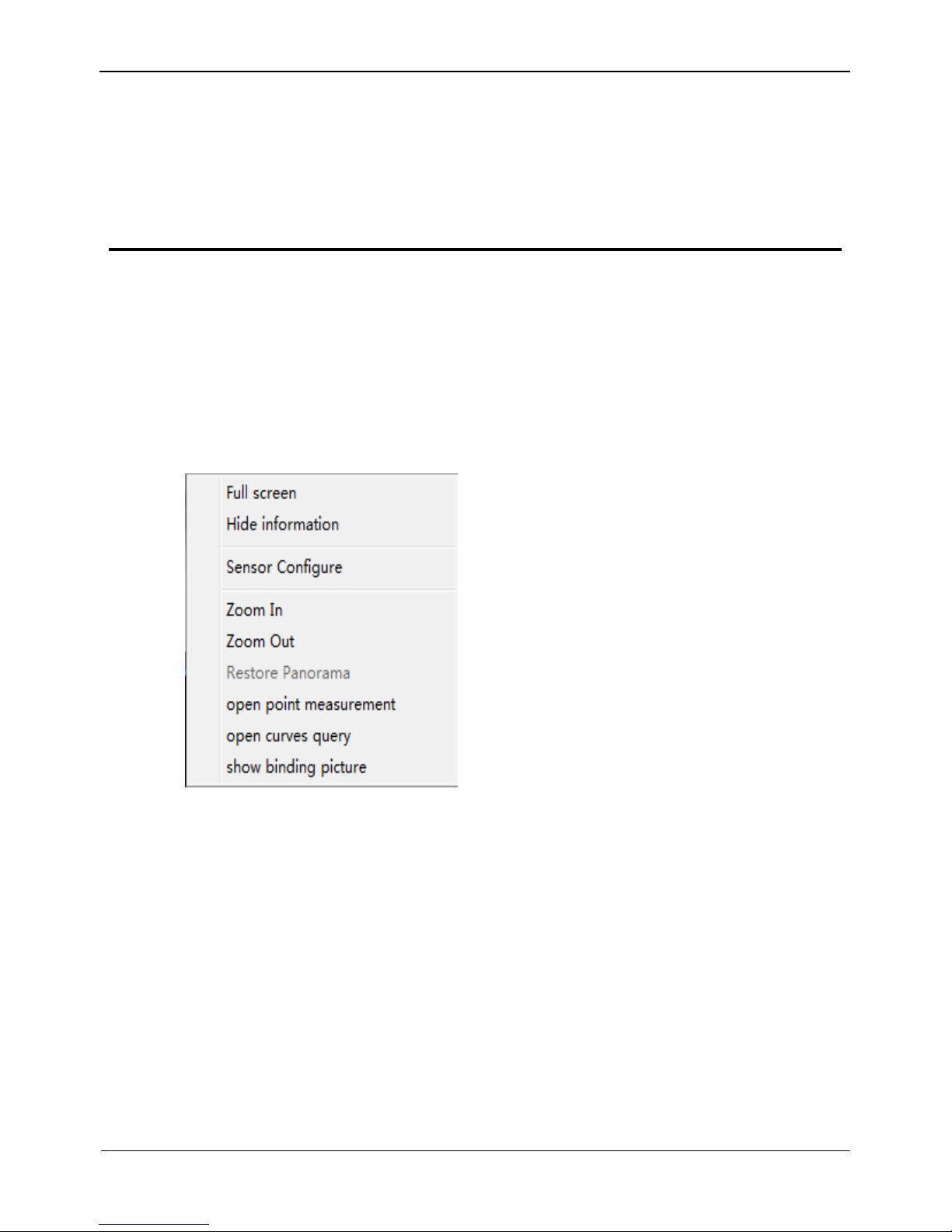
Step 1 On the web interface or client interface, right-click a monitoring screen, as shown in
Figure 5-1:
Figure 5-1 Sensor Setting
Step 2 Choose Sensor Setting and the Sensor Setting dialog box appears.
5.2 Image Setting
Figure 5-2 shows the image setting interface.
Page 22

Thermal Imaging IP Camera
User Manual
A Hazardous Substance Declaration
Issue V1.0 (2015-11-25) 21
Figure 5-2 Image setting interface
Table 5-1 describes the image setting parameters.
Table 5-1 Image setting parameter description
Parameter
Description
Configuration Method
Polarity
/LUT
The temperature field of a scenario detected
by the thermal imaging camera will be
mapped to the value range 0~255 by
algorithm processing. In the black/white
display mode, this range is converted into
tones of grayscale, for example, 0 indicates
fully black and 255 indicates fully white. By
this grayscale, the temperature field of the
scenario is converted into an image. Actually
displayed images vary with specific
polarity/LUT. The most frequently selected
modes are white hot (hot objects are brighter
than cold objects) or black hot (hot objects are
darker than cold objects). The difference
between these two modes is the reversal of
relationship between brightness and
temperature. Other optional modes include
rainbow and ironbow.
[Configuration
method]
Select from the dropdown list
[Default value]
White Hot
Page 23

A Hazardous Substance Declaration
Thermal Imaging IP Camera
User Manual
22 Issue V1.0 (2015-11-25)
Parameter
Description
Configuration Method
DVE Mode
Select a proper DVE mode based on the
contrast and detail characteristics of the image
shown. Available DVE modes include:
Default
Mode 1
Mode 2
[Configuration
method]
Select from the dropdown list
[Default value]
Default
Dynamic
DVE
Sharpness of thermal images is not as good as
visible light, so the original image is difficult
to identify. By the image enhancement and
edge processing technologies, the image can
be better identified. The value range of this
parameter is 0~112 and users can adjust the
value based on requirement.
[Configuration
method]
Drag the slide bar
[Default value]
0
Mirror
Allow users to select image pixel position:
Off: images are not flipped.
Horizontal: image is turned left/right.
Vertical: image is turned up/down.
Horizontal + vertical: image is turned
upside down.
[Configuration
method]
Select from the dropdown list
[Default value]
Off
5.3 FFC Mode
Figure 5-3 shows the FFC mode interface.
Figure 5-3 FFC mode interface
Page 24

Thermal Imaging IP Camera
User Manual
A Hazardous Substance Declaration
Issue V1.0 (2015-11-25) 23
Table 5-2 describes the FFC mode parameters.
Table 5-2 FFC mode parameter description
Parameter
Description
Configuration
Method
FFC Mode
The thermal imaging camera contains a mechanical
correction actuator to periodically improve image quality.
This actuator is called flat field correction (FFC). During
the control of FFC, the flat field shield blocks the sensor
array, enabling each part of the sensor to collect consistent
temperature field (flat field). Through FFC, the camera
updates the revision coefficient and thus generates more
consistent image. In the course of FFC, video image is
frozen for two seconds to show a static frame screen and
automatically restored after the correction. Repeating FFC
will avoid image particulate-like sense and quality
deterioration. When camera temperature changes, FFC is of
particular importance. For example, when the camera is
started up or ambient temperature changes, FFC must be
executed immediately.
Auto: In auto FFC mode, the camera will automatically
execute FFC in case that temperature change exceeds
specified amount or the specified time interval expires,
whichever is earlier. FFC interval range: 5~30 min. The
camera temperature change amount is subject to the set
value for the detector collecting internal temperature.
During camera startup, camera temperature changes
dramatically, so FFC will be performed repeatedly, which is
a normal phenomenon.
Manual: In manual FFC mode, the camera will not
automatically execute FFC in case of temperature change or
the specified time interval is up. Select manual FFC and
click Trigger Baffle Correction. If image quality is
obviously deteriorated but FFC is not automatically
executed, manually execute FFC to improve image quality.
External: In external FFC mode, the mechanical correction
actuator will stop and a unified source (black object) is set
in front of the camera. The internal FFC will not resolve
image deterioration that is caused by lens or lens base
inconsistency. The external FFC function will be very
useful. In actual operation, customers find that a hand palm
or desk surface with constant temperature can be used as a
substitute of the black object to perform external FFC.
[Configuration
method]
Select from the
drop-down list
[Default value]
Auto
Page 25

A Hazardous Substance Declaration
Thermal Imaging IP Camera
User Manual
24 Issue V1.0 (2015-11-25)
Parameter
Description
Configuration
Method
FFC
interval
(min)
In auto FFC mode, FFC interval range: 5~30 min
[Configuration
method]
Drag the slide
bar
[Default value]
15
Trigger
baffle
correction
In manual or external FFC mode, the camera will not
automatically execute FFC in case of temperature change or
the specified time interval is up. In this case, click Trigger
Baffle Correction.
-
5.4 DNR
Figure 5-4 shows the DNR interface.
Figure 5-4 DNR interface
Table 5-3 describes DNR parameters.
Page 26

Thermal Imaging IP Camera
User Manual
A Hazardous Substance Declaration
Issue V1.0 (2015-11-25) 25
Table 5-3 DNR parameter description
Parameter
Meaning
Configuration Method
3D NR
Reduce noise of image.
[Configuration method]
Select from the drop-down list
[Default value]
Off
2D NR
Reduce noise of image.
[Configuration method]
Select from the drop-down list
[Default value]
On
5.5 Lens Control
Table 5-3 shows the lens control interface.
Figure 5-5 Lens control interface
This interface is used to control focal distance of electrically-controlled lens.
5.6 Adjust the Screen
Figure 5-5 shows the screen adjustment interface.
Page 27

A Hazardous Substance Declaration
Thermal Imaging IP Camera
User Manual
26 Issue V1.0 (2015-11-25)
Figure 5-6 Screen adjustment interface
Table 5-4 Screen adjustment parameter description
Parameter
Meaning
Configura
tion
Method
Mode
selection
Compared with images generated based on visible light,
IR images boast the features of high background and low
contrast. In an IR image, background radiation occupies a
big part of dynamic display scope and the target object
occupies less dynamic display scope. If this object emits
weak IR ray, it will be submerged among the dark
background and difficult to be identified. To resolve the
problem, the IR image must be enhanced and
preprocessed. The thermal imaging camera allows an
image mode to be preset according to the temperature
distribution differences of a specific environment or
scenario so as to highlight the object:
Outdoor
Indoor
Sky/Earth
Sea/Sky
Linear
Universal
User-defined
[Configur
ation
method]
Select
from the
dropdown list
[Default
value]
Outdoor
Page 28

Thermal Imaging IP Camera
User Manual
A Hazardous Substance Declaration
Issue V1.0 (2015-11-25) 27
6 Technical Specifications
Table 6-1 describes the technical specifications of the all-in-one thermal imaging
IP camera.
Table 6-1 Technical specification
Item
Parameter
Description
Detector
Detector type
Non-cooling IR focal plane sensor
Sensing method
Microbolometer
Pixel
420*315
Pixel pitch
25um
Response
wavelength
8um~14um
Thermal
sensitivity NETD
50mK
Frame frequency
50 Hz /60Hz
Video
feature
Fixed-focus lens
8mm / 15mm / 25mm / 35mm / 50mm (optional)
Focus adjustment
method
Manual
FOV
75.4o*54.4o/39.7o*29.8o/23.7o*17.9o/17o*12.8o/
11.9o*9o
F value
1.0
Valid distance
(body)
60m/110m/180m/250m/350m
Valid distance
(vehicle)
120m/200m/350m/500m/650m
Temperatur
e measuring
Temperature
measuring
function
Allow users to set measuring point or area and
show and detect temperature: point measuring
(with mouse), area measuring (highest
temperature), and full-screen measuring (highest
temperature) (functioning as a temperature
measuring and prewarning product).
Temperature
measuring alarm
Overtemperature prewarning, overtemperature
alarm, temperature change trend alarm, and
temperature difference alarm (functioning as a
temperature measuring and prewarning product)
Page 29

A Hazardous Substance Declaration
Thermal Imaging IP Camera
User Manual
28 Issue V1.0 (2015-11-25)
Item
Parameter
Description
Functional
Feature
Polarity /LUT
mode
Black hot/white hot/rainbow/ironbow
DVE image
enhancement
0~6 levels
Correction
Manual/Auto/External
Noise reduction
Support,2D/3D
Contrast
adjustment
1~4 levels
Mirroring
Support
OSD display
Support
Image
feature
Output image
resolution
D1/CIF
Frame rate
30fps
Encoding
feature
Video
compression
format
H.264BP/MP/HP/MJPEG
Audio
compression
format
G71,AMR,RAW_PCM
Multi-code
stream
Support
Code rate control
CBR/VBR
Code stream
scope adjustment
50Kb~4Mb
Network
features
Network protocol
IPv4/IPv6 、 RTSP/RTP/RTCP 、 TCP/UDP 、
HTTP 、 DHCP 、 DNS 、 FTP 、 DDNS 、
PPPOE、SMTP、SIP
Storage
communication
protocol
CIFS、NFS
Web
management
Embedded Web service, which can be viewed and
configured through the IE explorer
Remote upgrade
and maintenance
Support
Integration
feature
In support of ONVIF/third-party protocol
Page 30

Thermal Imaging IP Camera
User Manual
A Hazardous Substance Declaration
Issue V1.0 (2015-11-25) 29
Item
Parameter
Description
Maximum user
access amount
10
Interface
features
Network
interface
RJ-45,10/100Base-T
Audio interface
1 audio input and 1 audio output
Alarm interface
2 alarm input and 2 alarm output
Analog video
output interface
BNC,750hm
PTZ control
interface
RS485
SD card interface
Micro SD,HCSD card, MAX 32G
System
function
features
Intelligent alarm
Motion detection alarm, I/O alarm, disk alarm
Heartbeat
mechanism
Support
Storage method
Local storage, NAS storage, SD card storage
Privacy masking
Five areas can be set and the area size can be
adjusted.
Character display
Time, date, channel number, channel name, and
user-defined content
Security
Password protection; in support of multi-level user
group management; permission customization;
one-button reset
Reliability
Watchdog for hardware and software; automatic
fault rectification
physical
features
Power supply
Power
consumption
Operating
temperature
Operating
humidity
Protection level
Installation mode
Wall-mounting mode, ceiling mode
Dimension
φ110mm*388mm
Weight
1900g(25mmlens)
Page 31

A Hazardous Substance Declaration
Thermal Imaging IP Camera
User Manual
30 Issue V1.0 (2015-11-25)
A Hazardous Substance Declaration
Component
Hazardous Substance or Element
Plumbum
(Pb)
Mercury
(Hg)
Cadmium
(Cd)
Hexavalent
Chromium
(Cr6+)
Polybrominated
Biphenyls (PBB)
Polybrominated
Diphenyl Ethers
(PBDE)
Structural
part
× ○ ○ ○ ○
○
Board/circuit
module
× ○ ○ ○ ○
○
Cable
connector
× ○ ○ ○ ○
○
Accessories
× ○ ○ ○ ○
○
○: indicates that the concentration of the hazardous substance in all homogeneous substances of the
component is within the limit specified in SJ/T 11363-2006 Requirements for Concentration
Limits for Certain Hazardous Substances in Electronic Information Products.
×: indicates that the concentration of the hazardous substance in at least one homogeneous substance
of the component exceeds the limit specified in SJ/T 11363-2006 Requirements for Concentration
Limits for Certain Hazardous Substances in Electronic Information Products.
101-500-0152-01
 Loading...