

Page 1

12000 Ford Road, Suite 110
Dallas, TX 75234 Tel: 972-247-1203 Fax: 972-247-1291
www.idview.com
IP Camera
(Network Camera)
User Manual
Page 2

2
12000 Ford Road, Suite 110
Dallas, TX 75234 Tel: 972-247-1203 Fax: 972-247-1291
www.idview.com
Important Safeguards and Warnings
Do not place heavy objects on the DVR.
Do not let any solid or liquid fall into or infiltrate the DVR.
Please brush printed circuit boards, connectors, fans, machine box and so on regularly.
Before the dust cleaning please switch off the power supply and unplug it.
Do not disassemble or repair the DVR by yourself. Do not replace the components by
yourself.
Environment:
Please place and use IP camera under temperature between-10oF~140oF and humidity
less than 9%;
Do not use IP camera in smoky or dusty environment;
Avoid collision or strong fall.
Please insure the IP Camera level installation in a stable workplace.
Please install in ventilated place. Keep the vent clean.
Use within the rating input and output scope.
Suitable products:
This manual is suitable for all series of IP Camera from our company, including indoor
box type, IR waterproof type, whelk type, dome type, home-use robot type, etc.
Special announcement:
The content including in this manual refers to the most updated information when
compilation, if there is something to be changed, will not further notice specially.
If got questions or requirement, please feel free to contact us at any time.
Page 3

3
12000 Ford Road, Suite 110
Dallas, TX 75234 Tel: 972-247-1203 Fax: 972-247-1291
www.idview.com
Catalogue
Chapter One: Product introduction
1.1 Product summary
The IP cameras can be applied as a part of a safety surveillance network. With the professional
network video surveillance software it achieves the strong network communication ability and
telecommunication ability. And IPC can individually work also.
The series DVR is designed specially for security and defense field which is an outstanding digital
surveillance product. It introduces embedded LINUX operating system which is more stable. It introduces
standard H.264mp video compressed format and G.711A audio compressed format which insures the
high quality image, low error coding ratio and single frame playing. It introduces TCP/IP network
technology which achieves the strong network communication ability and telecommunication ability.
It is applied to all kinds of occasion that need network remote monitoring, such as:
ATM, Bank counter, supermarket, factory, etc.
Foster care center, kingdom garden, school, etc.
Intelligent gate control system.
Intelligent building and residential manage system
Unattended system like: Generating plant, telecom base station
Outdoor device to monitor bridge, tunnel, block transportation status
Production line and warehouse control.
24-hour monitor for road transportation.
Remote monitor for forest, water source and river.
Airport, train station, bus stop, etc.
1.2 Porduct main function
Real-time surveillance
Page 4

4
12000 Ford Road, Suite 110
Dallas, TX 75234 Tel: 972-247-1203 Fax: 972-247-1291
www.idview.com
·with analog output interface can do surveillance through device of monitor or DVR, etc.
Storage
·Max support TF card with 32G (part of model support) for local storage of snapshot image.
·can do snapshot remote storage via CMS software or Myeye platform
·storage data is using dedicated format, can not be modified to ensure data safety
Compression format
· Audio and video signal is compressed by individual hardware, to make the image and voice
synchronously stable
Backup function
·client side pc can download file from TF card for back up via network
Video playback function
·can do full real-time record, and search, net surveillance, video search and download, etc.
·support play back, mode of fast-play, slow-play etc.
·can do partial enlargement of any of the area
Network operation function
·can remote surveillance via network (including mobile)
·remote PTZ control
·remote video search and real time playback
Alarm linkage function
·alarm link to record, snapshot, email sending, etc.
Telecom interface
·with RS485 interface for PTZ control
· with Ethernet port for remote access function , remote upgrade & maintain function.
Intelligent operation
·for the same setting operation on menu can do copy & paste operation.
Page 5

5
12000 Ford Road, Suite 110
Dallas, TX 75234 Tel: 972-247-1203 Fax: 972-247-1291
www.idview.com
Chapter Two: Open case checking and cable connection
2.1 Open case checking
When you receive this product,
Firstly, check model No. on product is the same as what you ordered;
Then, check if there is obvious damage on packing; the protective material used for packing can
afford most unexpected strike during transportation;
Finally, please take out IPC and remove the protective covers to check if there is obvious damage.
2.2 TF card installation
Remark: Please check if the model you bought whether support TF card
For primary use, firstly please install TF card, one TF card, to keep normal function, TF card is
required with minimum 4G and maximum 32G.
Part of IPC such as robot type can insert TF card directly from outside case, other IPC that support
TF card, need to open the case and find TF card slot to insert it.
2.3 Installation on brace
The IPC is using the standard case, so it can be installed to a standard brace.
Installation steps and attentions:
1、make sure the temperature is between -14oF~140oF ,humidity is less than 90%;
2、brace installed stable and firmly;
3、outdoor installation please pay attention to the severe weather;
4、when installing multi-device on the same line, please take protective measure to avoid over load
of the line.
Page 6

6
12000 Ford Road, Suite 110
Dallas, TX 75234 Tel: 972-247-1203 Fax: 972-247-1291
www.idview.com
2.4 Video output connection
2.4.1 choose and connect video output device
1.BNC output:
BNC video output is divided into: PAL/NTSC BNC(1.0V
P-P
,75Ω),can be connected to monitor or
surveillance integrated equipment such as DVR, etc.
BNC output can support preview of the monitor image only.
Make sure the stable and reliable of transmission link:
The video transmission line should adopt high quality coaxial pair which is chosen by the
transmission distance. If the transmission distance is too far, it should adopt shielded twisted pair, video
compensation equipment and transmit by fiber to insure the signal quality.
The video signal line should be away from the electro magnetic Interference and other equipments
signal lines. The high voltage current should be avoided especially.
Insure the connection stable and credible
The signal and shield lines should be firm and connected credible which avoid false and joint
welding and oxidation.
2. Network output:
Connect to LAN and WAN via common standard, using the PC that is in the same LAN line with IPC by
software or IE browser to set parameters, real-time preview, remote playback and download, etc.
When replace the monitor by the computer display, there are some issues to notice.:
1、do not make it running for a long time, in order to extend the using life of device.
2、regularly degauss to keep monitor normally work.
3、Keep away from device with severe electromagnetic interface.
TV is not a credible replacement as a video output. It demands reducing the use time and
control the power supply and the interference introduced by the nearby equipments strictly. The
creepage of low quality TV can lead to the damage of other equipments.
Page 7

7
12000 Ford Road, Suite 110
Dallas, TX 75234 Tel: 972-247-1203 Fax: 972-247-1291
www.idview.com
Chapter Three: IE log-in basic operation
Remark: keys in grey means do not support
3.1 Boot
Connect to power, then IPC is auto boot.
Remark:1. Make sure that the input voltage corresponds with the switch of the DVR power supply.
2. Power supply demands: 220V±10% /50Hz.
Suggest using the UPS to protect the power supply under allowable conditions.
3.2 Reboot
Reboot IPC is divided into soft reboot and hard reboot. Soft switch please enter【Devicecfg】>
【Advanced】 choose【reboot】; Hard reboot, to cut off power and reconnect it to reboot device
Illustrate:
1、Power-off & recover function
If IPC happens with abnormal shut down when it is under recording, after reboot, it will
auto-save the record info before shutdown and restore to status before shutdown.
2、Change TF card
When change TF card, please cut off power supply firstly.
3、Change battery
IPC is using button cell battery, need regularly check system time, if time is not accurate, then
need to change battery. Suggest to change it once a year by professional maintainer and using
the same model of battery.
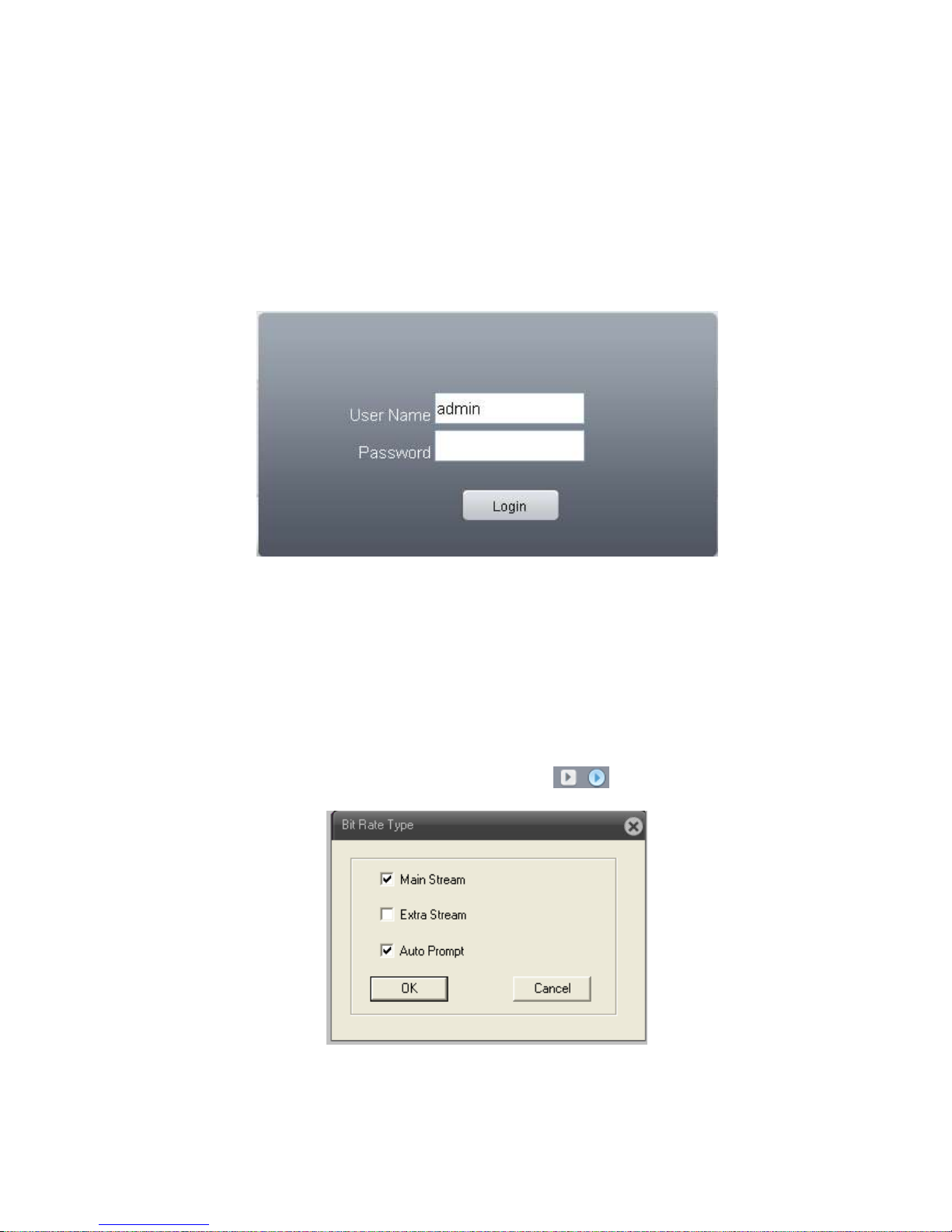
3.3 Log-in
When device turns on normally, need to log-in before operation, system will base on the authority of
Page 8
8
12000 Ford Road, Suite 110
Dallas, TX 75234 Tel: 972-247-1203 Fax: 972-247-1291
www.idview.com
log-in user to provide related function.
Default IP address:192.168.1.10,subnet mask:255.255.255.0,gateway:192.168.1.1
When device ex-fty, there are 3 preset users : admin、guest、default,default password is none,
admin is preset as super authority user, guest and default is preset with authority of preview and
playback, admin and guest user can modify password but not authority, default is the user default log-in,
can modify authority but not password
Pic : 3.1 Log-in
For safety sake, when firstly log-in, please go to “Account” to modify user name and
password, see chapter 4.5.2 account manage).
3.4 Preview
After log-in successfully, will come out window of bit rate type as pic 3.2, can choose the main
stream or extra stream u want for preview, and also can click at left side of preview page to set it.
Pic: 3.2 bit rate type
Page 9
9
12000 Ford Road, Suite 110
Dallas, TX 75234 Tel: 972-247-1203 Fax: 972-247-1291
www.idview.com
At preview page, can shows date, time and channel titile.
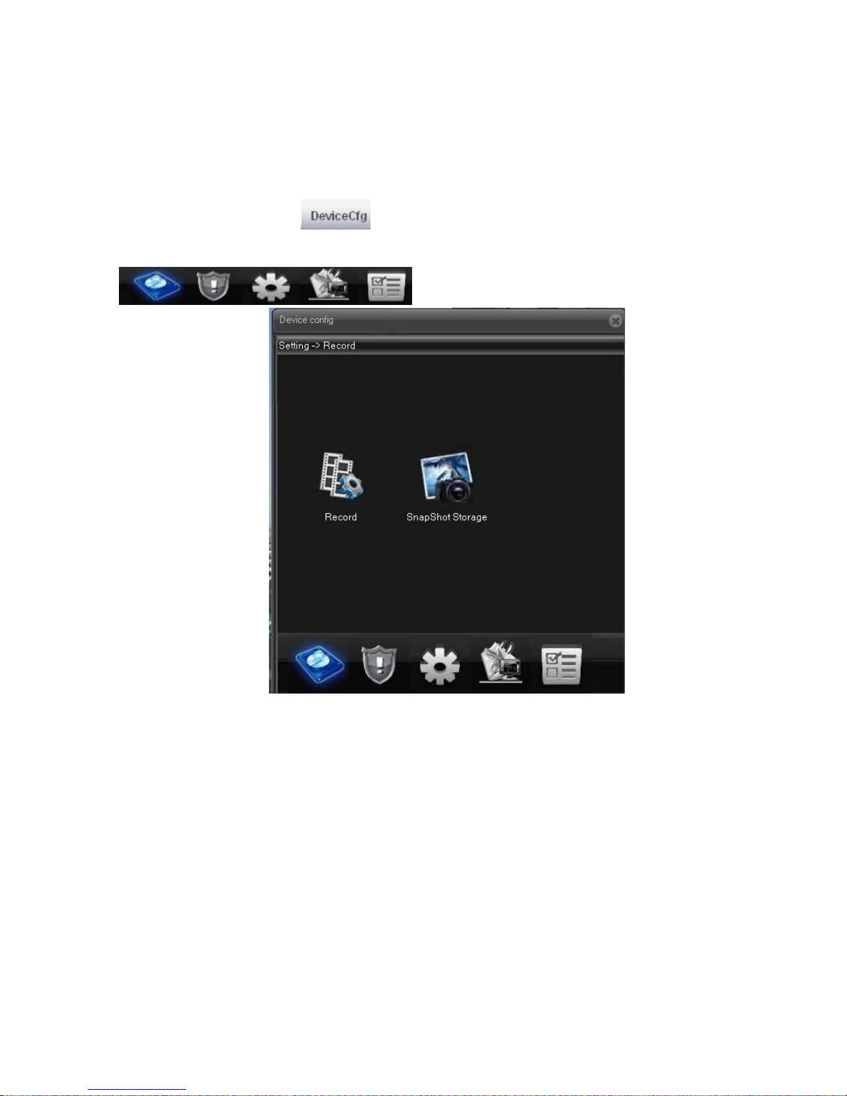
3.5 Setting menu
On preview mode, click at top side ,,will come out window as pic:3.3. setting menu
function including: Record, Alarm, System, Advanced, Info. Click icon at bottom side
will enter related next menu of this function.
Pic: 3.3 shortcut menu
3.5.1 Record
Record function including: device record and snapshot settings.
1. Record setting
Device should install TF card to realize this function.
Page 10
10
12000 Ford Road, Suite 110
Dallas, TX 75234 Tel: 972-247-1203 Fax: 972-247-1291
www.idview.com
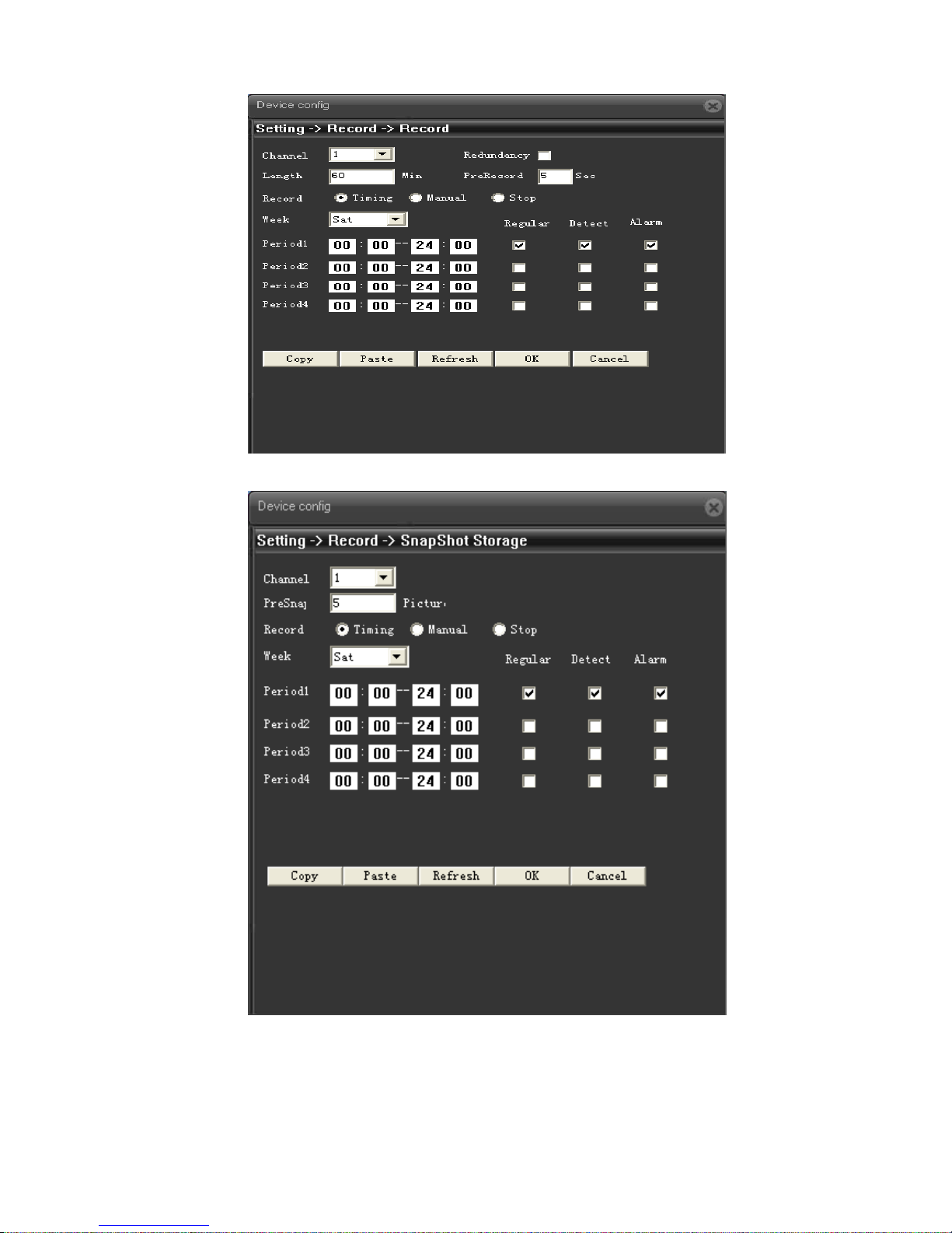
Pic: 3.4 Record setting
Pic: 3.5 Snapshot setting
Page 11
11
12000 Ford Road, Suite 110
Dallas, TX 75234 Tel: 972-247-1203 Fax: 972-247-1291
www.idview.com
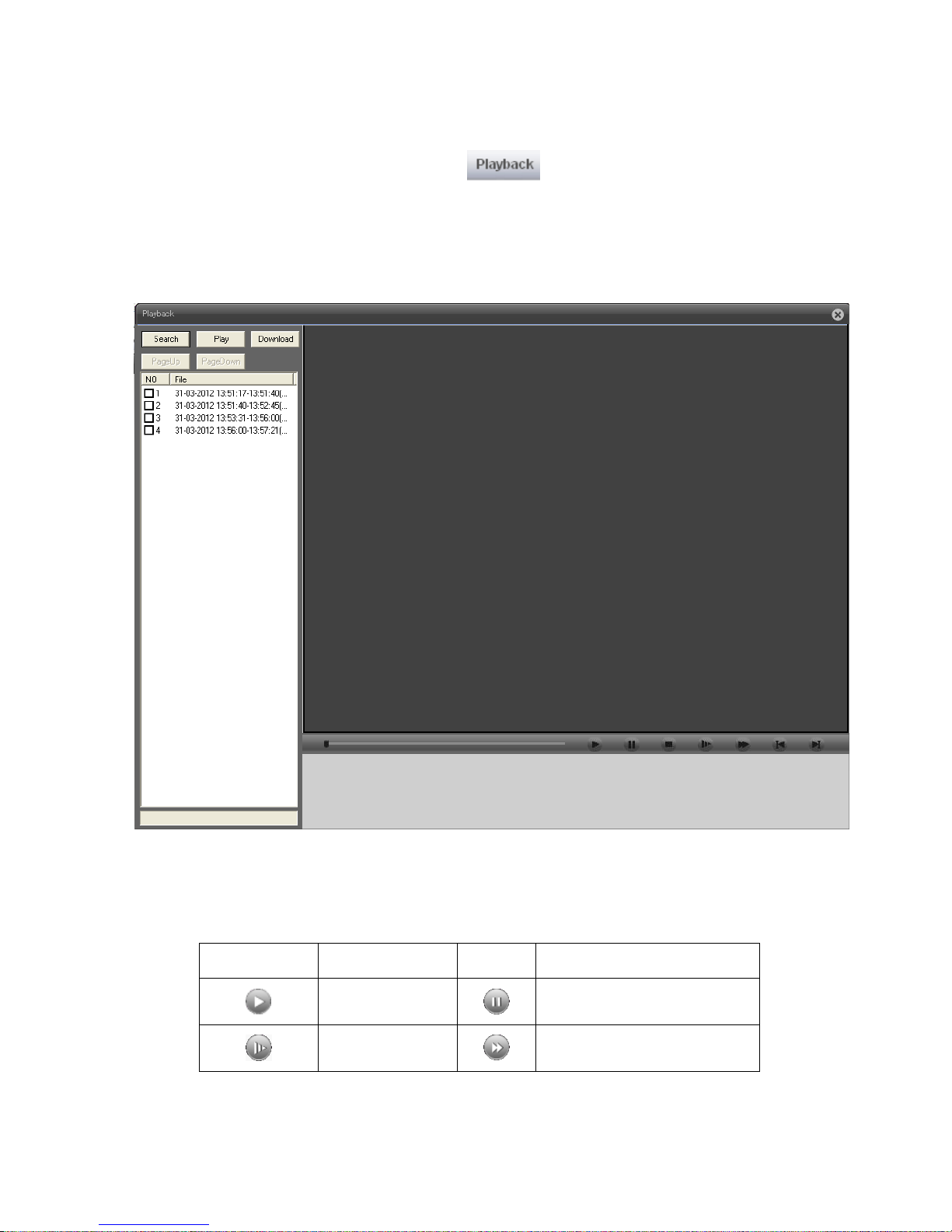
3.5.2 Playback
To play the video file in TF card, can click at upper left side on monitor page, to enter video
playback page.
Remark: Device normal playback, the TF card that used for video storage should be set as
read/write or read only (please refer to HDD manage).
Pic 3.6 Playback
【Playback control button】see detail in below chart;
Button
Function
Button
Function
Play Pause
Slow-play Fast-play
Page 12

12
12000 Ford Road, Suite 110
Dallas, TX 75234 Tel: 972-247-1203 Fax: 972-247-1291
www.idview.com
Previous frame
Next frame
Stop
Chart 3.1 playback control button list
Remark:Playback by frame should under the status of playback pause.
【Operate tips】to show the button function when cursor point it
Special feature:
Partial enlargement:when single view full screen playback, can use right button to choose any
size of area from the image, click left button in the chosen area, can enlarge this area to
playback, double click left button will exit.
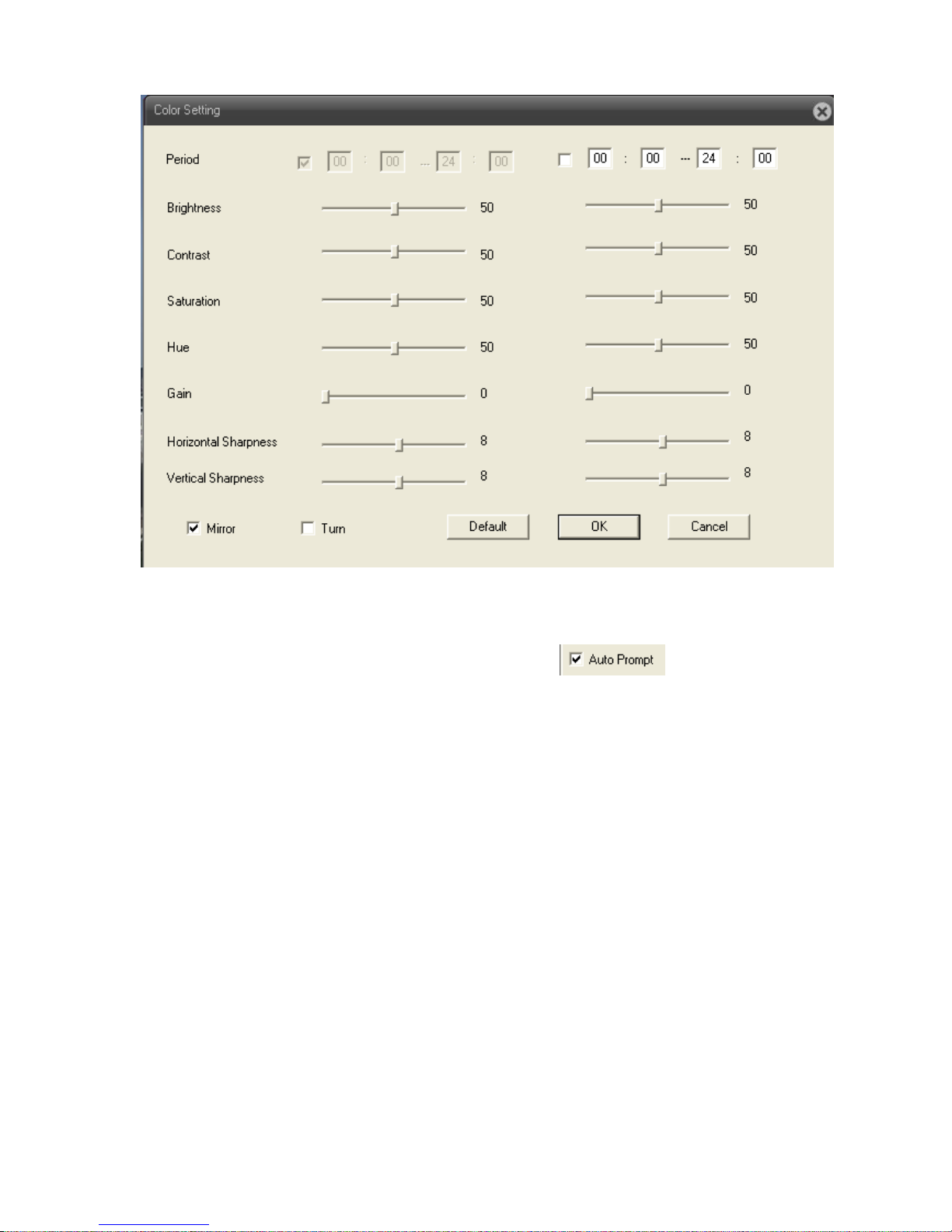
3.5.3 Image color
Set image parameter of chosen channel (when single view preview, it should be current channel,
when multi-view preview, it should be the channel where the cursor stay), you can enter the page by
shortcut menu. Image parameters including: brightness, contrast, saturation, hue, gain, horizontal and
vertical sharpness. Also can base on requirement to set different image parameter in different period.
Page 13
13
12000 Ford Road, Suite 110
Dallas, TX 75234 Tel: 972-247-1203 Fax: 972-247-1291
www.idview.com
Pic: 3.7 Color setting
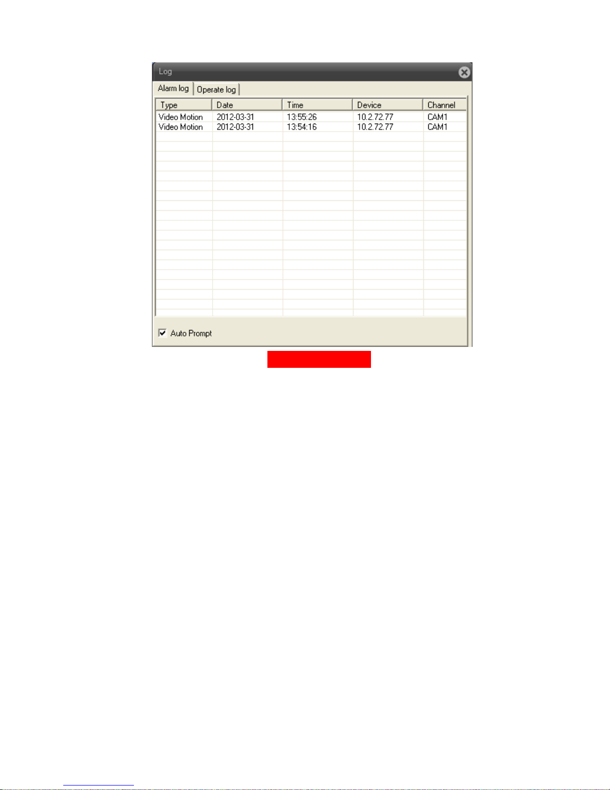
3.6 Log
Show alarm information and operation record, if u tick at lower left side, when
alarm happens, window tip will auto come out.
Page 14
14
12000 Ford Road, Suite 110
Dallas, TX 75234 Tel: 972-247-1203 Fax: 972-247-1291
www.idview.com
Pic: 3.8 Log information
Page 15

15
12000 Ford Road, Suite 110
Dallas, TX 75234 Tel: 972-247-1203 Fax: 972-247-1291
www.idview.com
Chapter Four: Main Menu
4.1 Main menu guideline
Main Menu
Submenu
Function summary
Record
Record
Set record config, record type, record period, etc.
Snapshot
Set snapshot period, type , etc.
Alarm
Video
motion
Set motion detect alarm channel, sensitivity, area, linkage
parameters: alarm output, snapshot, recording, PTZ, email
sending, ftp upload, etc.
Video blind
Set video blind alarm channel, sensitivity, linkage parameters,
alarm output, snapshot, recording, PTZ, email sending and
ftp upload, etc.
Video lost
Set video lost alarm channel and linkage parameters: alarm
output, recording, snapshot, PTZ, Email sending, FTP
upload, etc.
Alarm input
Set alarm input channel and linkage parameters: alarm
output, recording, snapshot, PTZ, email sending, FTP upload,
etc.
Alarm
output
Set alarm mode: configuration, manual, stop
Abnormal
Storage device not exist, not enough space, access storage
device fail, IP conflict, network abnormal alarm
System
General
Set system time, data format, language, hard disk full time
operation, machine number, video format, output mode,
summertime, stay time
Page 16

16
12000 Ford Road, Suite 110
Dallas, TX 75234 Tel: 972-247-1203 Fax: 972-247-1291
www.idview.com
Encode
Set encode mode: encode mode, resolution, frame rate, bit
rate, image quality, code stream value, I frame interval
parameter, video/audio enable.
Network
Set basic net parameter, and DHCP、 DNS parameter,
auto-gain IP address, network high-speed download, net
transmission tactics
Net service
ARSP、Mobile monitor、UPNP、FTP、WiFi、3G、alarm center、
RTSP、PPPOE、NTP、Email、IP authority、DDNS parameter,
etc.
GUI display
Set channel title, cover area, time title, channel time overlap
and position
PTZ Config
Set channel, PTZ protocol, address, baud rate, data bit, stop
bit, parity
RS485
Set protocol, address, baud rate, data bit, stop bit, parity
RS232
Set serial port function, baud rate, data bit, stop bit, parity
Camera
parameter
Exposure mode, Day/Night mode, Backlight compensation,
Auto iris, profile, AE reference, AGC, slow shutter, IR_CUT,
Image、Over-turn、anti-flicker etc
Advanced
HDD
Manage
Do operation to TF card, such as set read/writ, read only,
redundant, format disk, recover, partition, etc.
Account
Modify user, group or password. Add user or group. Delete
user or group.
Auto
maintain
Set auto reboot system, time to auto delete file
Default
Restore setting status of : regular, encode, record, alarm,
network, net service, GUI display, serial settings, account
manage
Page 17

17
12000 Ford Road, Suite 110
Dallas, TX 75234 Tel: 972-247-1203 Fax: 972-247-1291
www.idview.com
Import &
Export
Config import, Config export, Log export
Upgrade
To do net upgrade via IE or client software
Reboot
IPC soft reboot
Info
HDD info
Show ttl space of HDD, type, space left, record time, etc
Log
Can base on record type and time to search log, can clear the
log information
Version
Show alarm input output, system version, build date, etc
4.2 Record
Device do operation regarding record, including: record & snapshot.
4.2.1 Record setting
Set IPC parameter, when firstly turn on, system is default with record for 24hours. You can go to
【Device config】>【Record】>【Record】to do related setting.
Remark: Device installed with TF card and set it as Read/Write, then it can normally record.(detail
please refer to chapter 4.5.1 HDD manage)
Page 18

18
12000 Ford Road, Suite 110
Dallas, TX 75234 Tel: 972-247-1203 Fax: 972-247-1291
www.idview.com
Pic: 4.1 Record setting
【Length】to set the length of each recording file between 1-120min, default is 60min;
【PreRecord】to record 1-30s before motion happens (time length may slight different due to bit rate)
【Record control】set recode type: timing, manual & stop
Timing: Record according to the set video type (regular, detect and alarm)and time period.
Manual:Click the button and the according channel is recording no matter the channel in
any state;
Stop:Click the stop button and the according channel stops recording no matter the
channel in any state.
【Period】Set the time section of common recording, The recording will start only in the set range;
【Record type】Set recording type: regular, detect or alarm.
Regular:Perform the regular recording in the set time section. The video file type is “R”.
Detect:Trigger the “motion detect”, “camera mask” or “video loss” signal. When above
alarm is set as opening recording, the “detection recording” state is on. The video
Page 19

19
12000 Ford Road, Suite 110
Dallas, TX 75234 Tel: 972-247-1203 Fax: 972-247-1291
www.idview.com
file type is “M”.
Alarm:Trigger the external alarm signal in the set time section. When above alarm is set as
opening recording, the “detection recording” state is on. The video file type is “A”.
Remark:related alarm setting, please refer to chapter 4.3 alarm part.
4.2.2 Snapshot storage
Setup snapshot parameters for different channels.At first time it's set for 24hours snapshot
continuously, pls go to Main Menu->Record->Snapshot Storage for appropriate settings.
Remark:Device installed with TF card and set partition, Snapshot should more than 1G, then device
can normally take snapshot.(detail please refer to chapter 4.5.1 HDD manage)
Pic: 4.2 Snapshot setting
【PreSnapshot】to take picture of 1-30 pcs before recording happens, default is 5 pcs
【Record】Set record type, "Timing" ,"Manual" and "Stop"
Timing: Realise snapshot according to record type(regular, detect and alarm) and period.
Page 20

20
12000 Ford Road, Suite 110
Dallas, TX 75234 Tel: 972-247-1203 Fax: 972-247-1291
www.idview.com
Manual: No matter what is the current status, once choose "manual" ,it will have
snapshot at related channels.
Stop: No matter what is the current status, once choose "stop", it will stop snapshot at
related channels.
【Period】Set normal record period, it only startup Snapshot Storage at set period.
【Type】Three types: regular, detect and alarm
【Record type】Three types: regular, detect and alarm
Regular: snapshot at set period
Detect: snapshot at set period when motion detect, video blind and video loss which are
preset for snapshot enable.
Alarm: snapshot at set period when alarm in which is preset for snapshot enable.
Note: for related alarm function, pls refer to chapter 4.3.
4.3 Alarm function
Alarm functions include: motion detect,video blind, video loss, alarm input and alarm output,
abnormal dealing.
Page 21

21
12000 Ford Road, Suite 110
Dallas, TX 75234 Tel: 972-247-1203 Fax: 972-247-1291
www.idview.com
Pic 4.3 Alarm function
4.3.1 Motion detect
When system detects the motion signal that reaches the set sensitivity, the motion detect alarm and
the linkage function is enable.
Page 22

22
12000 Ford Road, Suite 110
Dallas, TX 75234 Tel: 972-247-1203 Fax: 972-247-1291
www.idview.com
Pic: 4.4 motion detect setting interface
【Enable】 means enable motion detect function, enable it firstly then can do related setting.
【Sensitivity】base on sensitivity, can set 6 grades: ,the higher of sensitivity to the moving
objects, the easier to sense the motion happens;
【Region】ClickSetting,enter the setting region of PAL22X18,light blue region is the guard area of
motion detect, dark blue region is the unguard area (show the monitor page), see pic 4.5. press
left button of mouse, pull it to set region. (default whole region chosen is monitor area)
Page 23

23
12000 Ford Road, Suite 110
Dallas, TX 75234 Tel: 972-247-1203 Fax: 972-247-1291
www.idview.com
Pic: 4.5 region setting
【Period】Trigger the motion detect signal in the set time section, see pic:4.6. You can set according
to week or set uniformly. Each day is divided into four time sections.tick , mean setting is valid.
Page 24

24
12000 Ford Road, Suite 110
Dallas, TX 75234 Tel: 972-247-1203 Fax: 972-247-1291
www.idview.com
Pic 4.6 Time Period setting
【Interval】Only one alarm signal is turned on even there are several motion detect signals in the set
interval 0-600s.
【Alarm output】Start the external equipment of corresponding linkage alarm when the motion detect
alarm is turned on.;
【Delay】Delay a few moments and stop when the alarm state is turned off. The range is 10~300
seconds.
【Record channel】choose record, when alarm happens, system will trigger record signal of this
channel;
Remark:to link record, need to enable motion detect of related period at【record setting】
【Snapshot】choose snapshot, when alarm happens, system will trigger snapshot signal of this channe;
Remark:to link snapshot, need to enable motion detect of related period at【record setting】【record
setting】
【PTZ Linkage】when alarm happens, link the PTZ of related setting channel, see pic:4.7;
Remark:to link PTZ, need to set related parameter at【System】>【PTZ control】, set preset
point, cruise between points, interval, etc.
Page 25

25
12000 Ford Road, Suite 110
Dallas, TX 75234 Tel: 972-247-1203 Fax: 972-247-1291
www.idview.com
Pic: 4.7 PTZ linkage
【Delay】When alarm is over,recording will last some seconds(10~300sec),then stop.;
【EMAIL sending】tick ,means when alarm happens link email sending to inform user.
Remark:sending email, need to do related setting at【Net service】.
【FTP upload】tick ,means when alarm happens, if record or snapshot channel was chosen, the
record file and snapshot image will be uploaded to the appointed position.
Remark:FTP upload, need to do related setting at【Net service】.
4.3.2 Video blind
When the video image is influenced by the environment such as bad brightness or reaching the set
sensitivy parameter, the camera mask function is turned on and the linkage function is enable.
Page 26

26
12000 Ford Road, Suite 110
Dallas, TX 75234 Tel: 972-247-1203 Fax: 972-247-1291
www.idview.com
Pic: 4.8 video blind
Setting detail : refer to chapter 4.3.1 motion detect.
4.3.3 Video lost
When the equipment can not obtain the channel video signal, the video loss alarm is turned on and the
linkage function is enable.
Page 27

27
12000 Ford Road, Suite 110
Dallas, TX 75234 Tel: 972-247-1203 Fax: 972-247-1291
www.idview.com
Pic: 4.9 Video lost
Setting detail: refer to chapter 4.3.1 motion detect.
4.3.4 Abnormal
Analyze and detect the software and hardware of current device, when abnormal issue was
detected, device will make related respondence.
Page 28

28
12000 Ford Road, Suite 110
Dallas, TX 75234 Tel: 972-247-1203 Fax: 972-247-1291
www.idview.com
Pic: 4.10 abnormal
【Event type】choose event type at drop-down box,
【Enable】tick to enable,open abnormal deal function, setting is valid only if it is enable.
4.4 System setting
To set parameter of all kinds of functions, setting including: General、Encode、Network、Net
service、GUI display、PTZ config/RS485、RS232、Camera parameter.
Page 29

29
12000 Ford Road, Suite 110
Dallas, TX 75234 Tel: 972-247-1203 Fax: 972-247-1291
www.idview.com
4.4.1 General setting
Pic: 4.11 General setting
【System time】set current date and time of IP Camera.
【 Date format】 choose date showing format, including: year/month/date、 month/date/year,
date/month/year,
【Date separator】Choose list separator of the data format,
【Time format】choose time format, including: 24-hour and 12 hour;
【Language】at present support 29 kinds of language: simplified Chinese, Tradition Chinese,
English, Bosnian, Finnish, French, Greek, Hungarian, Italian, Japanese, Germany,
Polish, Portuguese, Russian, Spanish, Thai, Turkish, Vietnamese, Romanian,
Brazilian, Indonesian, Swedish, Arabic, Bulgarian, Czech, Hebrew, etc.
【HDD full】choose Stop record:means when the TF card is full, stop recording.
Choose Over write:means when the TF card is full, keep on recording, but the most
previous file will be replaced.
【Video standard】support PAL or NTSC;
Page 30

30
12000 Ford Road, Suite 110
Dallas, TX 75234 Tel: 972-247-1203 Fax: 972-247-1291
www.idview.com
【DST】Tick DST, then click 【setting】, will come out window as pic: 4.12 & pic:4.13, to set the start
time and end time of summertime via week or date.
Pic:4.12 DST (Week) setting
Pic:4.13 DST(Date) setting
4.4.2 Encode Seting
Set video/audio encode parameters, including image parameters of record file, remote monitor, etc.
Left part is to set the encode parameter of each separated channel, right part is to set encode parameter
of extra stream, dual stream is using one high bit rate stream for local high definition storage, support
D1/HD1/CIF/QCIF encode, one low bit rate stream(QCIF encode) for net transmission, in order to
maintain local storage and remote net transfer. Dual stream both considering to image quality and
transmission quality under the current band bottleneck, and can breakthrough it, base on the bandwidth
to flexibly choose stream format, to reach local high definition storage and low stream for net
transmission back end.
Remark:Main application of extra stream: to do multi-channel real-time monitor, and mobile monitor
when the network if poor.
Page 31

31
12000 Ford Road, Suite 110
Dallas, TX 75234 Tel: 972-247-1203 Fax: 972-247-1291
www.idview.com
Pic: 4.14 Encode setting
Encode setting
【Compression】Standard H.264MP;
【Resolution】show types of resolution: D1/HD1/CIF/QCIF;
【Frame rate】adjustable, real-time standard is: PAL,25 fps NTSC,30 fps;
【Bit rate type】you can choose CBR or VBR, image quality have 6 grades to choose under VBR
type, then you can manual choose the bit rate value under CBR type.
【Image quality】set bit rate value to change the image quality, if supporting facility is available, the
larger of bit rate value, the better of image quality.
Bit rate reference span: D1( 512~2560kbps) HD1( 384~2048kbps) CIF( 64~1024kbps) ,
QCIF(64~512kbps)
【Frame interval】you can choose between 2~12s;
Page 32

32
12000 Ford Road, Suite 110
Dallas, TX 75234 Tel: 972-247-1203 Fax: 972-247-1291
www.idview.com
【audio/video】the icon was all ticked, means audio & video combine stream
4.4.3 Network setting
Pic: 4.15 Network setting
【Net card】you can choose wired net card;
【DHCP enable】to auto get IP address(not suggested);
Remark:need to set up DHCP server in advanced.。
【IP address】set IP address of device, default IP address is: 192.168.1.10;
【subnet mask】set subnet mask of device, default subnet mask is:255.255.255.0;
【default gateway】set default gateway of device, default gateway is:192.168.1.1;
【DNS setting】Domain Name Server. It translates the domain name into IP address. The IP address
is offered by network provider. The address must be set and reboot then it works.;
Page 33

33
12000 Ford Road, Suite 110
Dallas, TX 75234 Tel: 972-247-1203 Fax: 972-247-1291
www.idview.com
【TCP port】default is 34567;
【HTTP port】default is 80;
【high speed download】Network high speed download;
【Transfer policy】there are 3 policies, adaptive, quality preferred, fluency preferred. Base on
different setting, code stream is auto-adjusted, adaptive is eclectic between quality and fluency, also
considers fluency when the quality is not greatly influenced. Fluency preferred and adaptive is valid only
when the extra stream is enable, if extra stream is not enable, it will base on network status to adjust
quality preferred
4.4.4 Net service
To config advanced network function, choose any item and double click it to config the parameters.
4.16 Net service
【PPPoE setting】
Page 34

34
12000 Ford Road, Suite 110
Dallas, TX 75234 Tel: 972-247-1203 Fax: 972-247-1291
www.idview.com
Pic: 4.17 PPPOE
Enabe:Tick means chosen, enable it firstly, then the setting is valid
Input user name and password that provided by ISP(Internet server provider), save it and reboot
device, after reboot, IPC will auto connect to network by the way of PPPoE, if it is successful【IP
address】will be changed to the dynamic WAN IP that just get.
Operation:PPPoE dial up successfully,check【IP address】,to get current IP of device, then access
this device by this IP from client side.
【NTP setting】
Pic: 4.18 NTP setting
Need to install NTP service at PC
Enable:tick means chosen, setting is valid only when it is enable.
Server IP:input IP of PC that installed with NTP server
Port:default NTP port is 123,can base on the actural NTP server to set port no
Time zone:London GMT+0 Berlin GMT +1 Cairo GMT +2 Moscow GMT +3 New Delhi GMT
+5 Bangkok GMT +7 Hongkong/Beijing GMT +8 Tokyo GMT +9 Sydney GMT +10 Hawaii
Page 35

35
12000 Ford Road, Suite 110
Dallas, TX 75234 Tel: 972-247-1203 Fax: 972-247-1291
www.idview.com
GMT-10 Alaska GMT-9 Pacific time GMT-8 US mountain time GMT-7 US central time GMT-6 US
eastern time GMT-5 Atlantic time GMT-4 Brazil GMT-3 Atlantic central GMT-2;
Update period:The same with the NTP server check interval. Default: 10minutes
【EMAIL setting】
EMAIL sending is used for sending alarm information and snapshot picture to appointed mailbox
when alarm link to snapshot.
4.19 EMAIL setting
SMTP server:address of email server,can be IP address or domain name(if it is domain name,
need to make sure the DNS is correct, then domain name can be correctly analyzed)
Port: Email server port number.;
SSL: Decide whether using Secure Socket Layer protocol to login;
User Name: Apply the email server user name.
Password: Input the password corresponding to the user.
Sender: Set the email sender address.
Receiver: Send the email to appointed receivers when the alarm is turned on. You can set three
receivers at most.
Title: You can set as you like.
【IP authority setting】
Page 36

36
12000 Ford Road, Suite 110
Dallas, TX 75234 Tel: 972-247-1203 Fax: 972-247-1291
www.idview.com
When choose the white list, only the IP in the list can connect to IP camera, list can support 64 IP
setting;
When choose the black list, mean the IP in the list can not access IP camera via net, list can support
64 IP setting.
Can tick to choose and delete the set IP.
Pic: 4.20 IP authority setting(black list) Pic: 4.21 IP authority setting(white list)
【DDNS】
Page 37

37
12000 Ford Road, Suite 110
Dallas, TX 75234 Tel: 972-247-1203 Fax: 972-247-1291
www.idview.com
Pic: 4.22 DDNS setting
To analyze server via dynamic domain name, choose DDNS type
Host domain name:Provide the domain name registered by DDNS;
Server domain name:the domain name that analyze server;
User name:Provide the account registered by DDNS.
Password:Provide the password registered by DDNS.;
When the DDNS is successfully configured and start, you can connect the domain name in the IE
address column to visit.
【FTP setting】
FTP is available only when alarm happens,or alarm activates record and snapshot,it will upload related
record and snapshot pictures to FTP server.
Pic: 4.23 FTP setting
【Enable】Click Enable,then all settings will be available
【Host IP】: IP address of FTP server;
【Port】Domain Port of FTP,default 21
【User Name】User name of FTP
【Password】Password of user
【Cryptonym】: tick means chosen, choose this, there is no need to set user name and password.
【Max File Length】Max length for upload files at every packed,default 128M
Page 38

38
12000 Ford Road, Suite 110
Dallas, TX 75234 Tel: 972-247-1203 Fax: 972-247-1291
www.idview.com
【Remote path】: the directory to upload file
Remark:the user should have the authority to upload file to server firstly.
【ARSP】
Startup DDNS server to add devices and manage it in the DDNS server
Pic: 4.24 ARSP setting
【type】: choose DNS
【Enable】: tick means chosen, setting is valid only when it is enable.
【server IP】: IP address of DDNS server
【Port No】: port No of device, corresponding to the listen port of DDNS;
【User name】: the user name that for device to log-in DDNS;
【Password】: password for above user name
【upgrade period】: Time interval of device synchronously to DDNS.
Remark:need to set up DDNS server before using
【Alarm center】
When alarm happens, report alarm information to alarm server
Page 39

39
12000 Ford Road, Suite 110
Dallas, TX 75234 Tel: 972-247-1203 Fax: 972-247-1291
www.idview.com
Pic: 4.25 Alarm center setting
【Protocol】protocol type is GENERAL;
【Enable】tick means chosen, setting is valid only when it is enalbe
【Server IP】IP address of Alarm Server;
【Port No】Port No. of device
【Alarm report】tick means chosen, report alarm information to server
【Log report】tick means chosen, report log information to server
【Mobile monitor setting】
To visit the device by mobile,pls make a router mapping of this port and use CMS to monitor and
operate it by protocol.
Pic: 4.26 Mobile monitor setting
【Enable】tick means chosen, open mobile monitor function, setting is valid only when it is enable.
Page 40

40
12000 Ford Road, Suite 110
Dallas, TX 75234 Tel: 972-247-1203 Fax: 972-247-1291
www.idview.com
【Port】port no for mobile monitor, which you need to make a router mapping of if want to visit it by
mobile
【UPNP】
UPNP protocol can auto port forwarding on router,make sure UPNP is enable on router before use
it.
Pic 4.27 UPNP setting
【Enable】tick means chosen,open UPNP function,setting is valid only when it is enable
【HTTP】: Route will automatically distribute HTTP port for the device, when IE viewing, it need this
port;
【TCP】: Router will automatically distribute TCP port for the device, when monitoring via CMS, it
need this port.
【MobilePort】Router will automatically distribute Mobile Port for the device, when mobile monitor, it
need this port.
4.4.5 GUI display
At local preview interface, including:Channel name, Time title, Channel title, Region cover
Page 41

41
12000 Ford Road, Suite 110
Dallas, TX 75234 Tel: 972-247-1203 Fax: 972-247-1291
www.idview.com
Pic: 4.28 GUI display
【Channel Name】Click the channel name modify button and enter the channel name menu. Modify
the channel name. The 16 Chinese characters and 25 letters are supportive.
【Time title】tick means chosen, to shows the system time on monitoring page;
【channel title】tick means chosen, show channel No at monitoring page.
【record status】tick means chosen, show the record status on monitoring page
【Alarm status】tick means chosen, show the alarm status on monitoring page.
【Transparency】choose the transparency of background image, span within: 128~255;
【Resolution】set resolution of monitor;
【Channel】choose channel No that set for encode output.
Page 42

42
12000 Ford Road, Suite 110
Dallas, TX 75234 Tel: 972-247-1203 Fax: 972-247-1291
www.idview.com
【 Region Cover 】 tick , choose region cover quantity, then click setting
,enter related channel, user can use mouse to choose any size of cover
region, (the covered region, video output should be in black)
【Time title】与【Channel title】set time title and channel title whether need be show out and the
position to show.
Pic: 4.29 region cover setting
Page 43

43
12000 Ford Road, Suite 110
Dallas, TX 75234 Tel: 972-247-1203 Fax: 972-247-1291
www.idview.com
Pic: 4.30 Channel and time title setting
Page 44

44
12000 Ford Road, Suite 110
Dallas, TX 75234 Tel: 972-247-1203 Fax: 972-247-1291
www.idview.com
4.4.6 RS232
Pic: 4.31 RS232
【Serial Port Function】Common serial port is used to debug and update program or set up specific
serial port.
【Baud rate】Choose the corresponding baud rate length
【Data bits】Include 5-8 options.
【Stop bits】Include 2 options;
【Parity】Include odd, even, mark, space.。
Page 45

45
12000 Ford Road, Suite 110
Dallas, TX 75234 Tel: 972-247-1203 Fax: 972-247-1291
www.idview.com
4.4.7 Camera parameter
Pic: 4.32 camera parameter
【Expose】can choose automatic(0.1 milisecond-80 millisecond), or manual(1/25,1/50,1/120,
1/250,1/500,1/1000,1/2000,1/4000,1/10000), default is automatic
【Day/night mode】can choose auto/color/ black and white, default is auto;
【Backlight compensation】can choose on or off;
【auto iris】can choose on or off;
【Porfile】can choose indoor or outdoor or auto, default is auto
【AE reference】can choose integers data between 0—100, default is 50;
【AGC】can choose on or off, limitation is between 0—100;
【Slow shutter】can choose none, low, medium, high, default is none.
Page 46

46
12000 Ford Road, Suite 110
Dallas, TX 75234 Tel: 972-247-1203 Fax: 972-247-1291
www.idview.com
【IR_CUT】can choose automatically switch or IR synchronous switch, default is automatically
switch
【Mirror image】tick ,means enable the convert of left and right of monitoring page
【Over turn】tick ,means enable the convert of up and down of monitoring page.
【Anti-flicker】tick ,enable anti-flicker to the fluorescent light.
【Front-end Command】fill in command and send out, front end of IP camera will carry out this
command
4.5 Advanced
Advanced menu including:HDD manage、Account、Auto Maintain、Default、Import & Export、
Upgrade、Reboot
4.5.1 HDD manage
To configure TF card that installed in device. Menu shows the information of current TF card,
including: type, status, total capacity. Operation to TF card including: set Read/Write, Read only,
Redundant, Format disk, Recover, Partition, etc. Select the TF card, then click function button on the
right side.
Remark:Read/Write:can read data and also can write data into it;
Read only:only can read data from the disk, but can not write data into it.
Page 47

47
12000 Ford Road, Suite 110
Dallas, TX 75234 Tel: 972-247-1203 Fax: 972-247-1291
www.idview.com
Pic: 4.33 HDD manage
4.5.2 Account
Manage the user authority of this device
Remark:1. The character length is 8 bytes at most for the following user and user team name. The
blank ahead or behind the character string is invalid.The middle blank in the character string is valid.
Legal characters include: letter, number, underline, subtraction sign, dot.
2. There is no limit in the user and user group. You can add or delete the user group according to
user definition. The factory setup include: user\admin. You can set the team as you wish. The user
can appoint the purview in the group.
3. The user management include: group/ user. The group and user name can not be the same. Each
user only belongs to one group.
Page 48

48
12000 Ford Road, Suite 110
Dallas, TX 75234 Tel: 972-247-1203 Fax: 972-247-1291
www.idview.com
Pic: 4.34 Account
【Modify User】Modify the existed user attribute.
【Modify Group】Modify the existed team attribute.
【Modify Password】Modify the user password. You can set 1-6 bit password. The blank ahead or
behind the char string is invalid. The middle blank in the char string is valid,
Note:The user who possess the user control authority can modify its own or other users
password
Pic: 4.35 Modify password
Page 49

49
12000 Ford Road, Suite 110
Dallas, TX 75234 Tel: 972-247-1203 Fax: 972-247-1291
www.idview.com
【Add user】Add a user in the team and set the user purview. Enter the menu interface and input the
user name and password. Choose the team and choose whether cover using the user. Cover using
means that the account can be used by multiple users at the same time.
Once choose the team the user purview is the subclass of the team.
We recommend that the common user’s purview is lower than the advanced user.
Pic: add user
【Add Group】Add a user team and set the purview. There are 36 different purviews: shut down the
equipment, real time surveillance, playback, recording setup, video file backup and so on.
Page 50

50
12000 Ford Road, Suite 110
Dallas, TX 75234 Tel: 972-247-1203 Fax: 972-247-1291
www.idview.com
Pic: 4.37 add group
【Delete user】Delete the current user. Choose the user and click delete user button.
【Delete Group】Delete the current group. Choose the group and click delete group button.
Pic: 4.38 delete group
4.5.3 Auto-maintain
The user can set the auto reboot time and auto file deleting time limit.
Page 51

51
12000 Ford Road, Suite 110
Dallas, TX 75234 Tel: 972-247-1203 Fax: 972-247-1291
www.idview.com
Pic: 4.39 auto maintain
4.5.4 Default
The system restore to the default setup. You can choose the items according to the menu.)
Page 52

52
12000 Ford Road, Suite 110
Dallas, TX 75234 Tel: 972-247-1203 Fax: 972-247-1291
www.idview.com
Pic: 4.40 default
Page 53

53
12000 Ford Road, Suite 110
Dallas, TX 75234 Tel: 972-247-1203 Fax: 972-247-1291
www.idview.com
4.5.5 Upgrade
Pic: 4.41 system upgrade
【upgrade file】to select upgrade file via IE or client software to do upgrading.
4.5.6 Reboot
To do soft reboot of IP camera
4.6 Device info
Shows information of device, including:HDD info、Log , Version
4.6.1 HDD Info
Display the hard disk state: type, overall capability, residual capability, the recording time and so on.。
Page 54

54
12000 Ford Road, Suite 110
Dallas, TX 75234 Tel: 972-247-1203 Fax: 972-247-1291
www.idview.com
Pic: 4.42 HDD info
Tips:○ means that the hard disk is normal. X means that the hard disk is broken-down.- means that
there is no hard disk. If the user need to change the damaged hard disk, you must shut down the DVR
and take up all the damaged hard disks,then install a new one.
* behind serial number means the current working disk such as 1*. If the corresponding disk is
damaged, the information will show “?”.
4.6.2 Log
Base on set searching way to check log information
LOG type can be divided into:system operation, configuration operation, data management, alarm
affair, recording operation, user management, file management and so on. Set the time section to look
up and click the look up button. The log information will display as a list. (one page is 128 items) Press
Page up or Page down button to look up and press delete button to clear all the log information.
Page 55

55
12000 Ford Road, Suite 110
Dallas, TX 75234 Tel: 972-247-1203 Fax: 972-247-1291
www.idview.com
Pic: 4.43 Log info
4.6.3 Version
Display the basic information such as hardware information, firmware version, built date, serial
Number, and so on.
Page 56

56
12000 Ford Road, Suite 110
Dallas, TX 75234 Tel: 972-247-1203 Fax: 972-247-1291
www.idview.com
Pic: 4.44 version info
 Loading...