

Page 1
SERVICE MANUAL
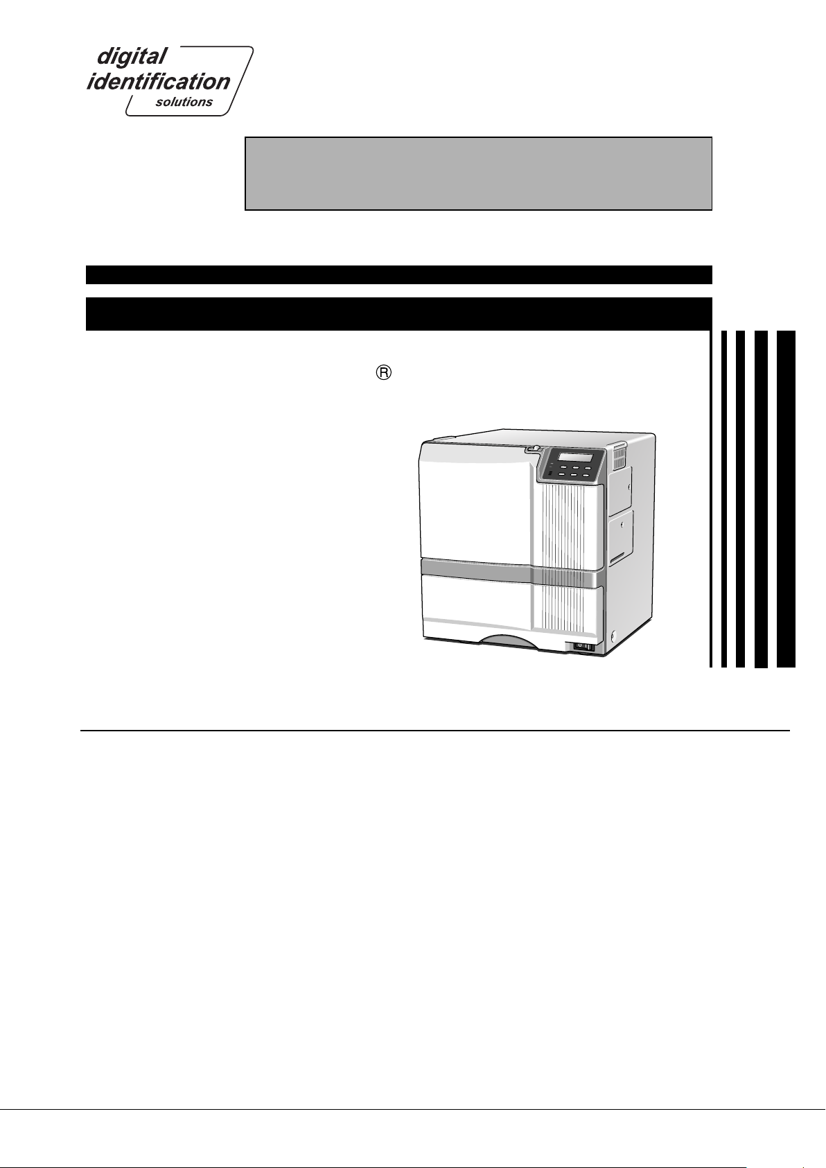
SUBLIMATION TYPE RETRANSFER PRINTER
EDI secure
XID580i
SPECIFICATIONS
Recording method : Sublimation type retransfer
Feed format : Automatic feed
Recording density : 300 dpi
Expression gradation
Printing time : Approx. 29 seconds (for
Interface : USB2.0 (standard)
Operating environment conditions
Storage environment conditions
Power supply : 100 — 120 V AC/
Current dissipation : 7.0A (for 100V system)/
Mass : Standard 22.0kg
: 256 gradations for each
color
single-sided printing,
excluding data transfer
time)
Temperature: 15°C ~ 30°C
Humidity: 35% ~ 70%
(no condensation)
Temperature: -15°C ~ 55°C
Humidity: 20% ~ 80%
220 — 240 VAC
(allowance±10%)
5.0A (for 200V system)
Excluding the built-in
magnetic encoder
Accessories : Power cable
*
The detached power cords and the Instruction
manual vary according to model and country of
purchase.
For 120 V AC
x 1
Dark gray (North America)
For 220 to 240 V AC
x 1
(Europe)
Instruction manual
English
x 1
Card stacker
×1
Ink ribbon cassette
×1
Retransfer film cassette
×1
Jog lever (contained in the
card tray)
×1
CX21ICL Series (Large-type IC unit)
Power supply : Fed from the printer.
5V±5% DC, 12V±5% DC, 24V±5%
DC
Current dissipation : 500mA, 300mA, 1A
Mass : 3.5kg
Dimension (mm) : 110(W) × 221(D) × 255(H)
Accessories :Joint plate × 1
Inter-unit cable × 1
CX21ICS Series (Small-type IC unit)
Power supply : Fed from the printer.
Mass : 0.5kg
Dimension (mm) : 50(W) × 152(D) × 115(H)
Accessories : Screw (with washer) × 3
Screw (without washer) × 2
Products sold separately
: Ink ribon, retransfer film : Cleaning card
1,000 frames/set 10 card /set
Model : CY-P340A Model : CX210-CC1
: Laminator Unit :
Model : ILU
: Card tray
When setting paper feeding feature on the right
Model: CF-3NTR
: Hand gloves M Size (U105-M)
L Size (U105-L)
KAS-T099-002
May 2006
Page 2

CONTENTS
IMPORTANT SAFETY PRECAUTIONS
INSTRUCTIONS
MODEL NAME ................................................................................. 1
1. Detailed specifications .................................................................... 1
HOW TO CONNECT SEPARATELY SOLD PARTS .................. 2
1. Connecting the Small IC Unit ..........................................................2
2. Connection of the Magnetic/Contact-type IC Encoder ....................3
3. Connecting card tray .......................................................................4
BLOCK DIAGRAM .......................................................................... 5
1. OVERALL BLOCK DIAGRAM .........................................................5
2. BLOCK DIAGRAM OF PRIMARY SIDE OF POWERUNIT .............6
3. INTERLOCK SW BLOCK DIAGRAM .............................................. 7
4. BLOCK DIAGRAM OF THE FPGA CIRCUMFERENCE
ON A CPU BOARD ................................................................... 8
WIRING DIAGRAM ....................................................................... 9
Main Parts Layout..........................................................................10
1. Sensor-related...............................................................................10
2. Related to Thermal Head and Rollers ........................................... 10
3. Motor-related ................................................................................. 11
4. Solenoid-RELATED ....................................................................... 11
5. Switch-related ............................................................................... 12
6. Related to Circuit Boards, Power Supply Unit, and Fans .............. 12
7. RF-ID .............................................................................................14
REMOVAL AND EXCHANGE OF THE MAIN PARTS ............ 15
1. CHECKING AT THE TIME OF SERVICING .................................. 15
1.1 REMOVE THE TOP COVER AND THE REAR PANEL. ..........15
1.2 REMOVE THE MG CIRCUIT BOARD. .................................... 15
1.3 SWING DOWN THE POWER SUPPLY UNIT. ........................ 16
2. REMOVAL AND EXCHANGE OF THE MAIN PARTS ...................16
2.1 REMOVAL OF THE HEAT ROLLER ....................................... 16
2.1.1 Removal of the Bend Remedy Roller ............................... 16
2.1.2 Removal of the Heat Roller .............................................. 16
2.2 REMOVAL OF THE CAM MOTOR .......................................... 17
2.2.1 Installation of the Cam Motor ........................................... 18
2.3 REMOVAL OF THE RETRANSFER FILM SUPPLY
MOTOR............................................................................18
2.3.1 Installation of the Retransfer Film Supply Motor...............19
2.4 REMOVAL OF THE RETRANSFER FILM TAKE UP
FILM WINDING MOTOR .................................................. 20
2.5 REMOVAL OF THE CARD FEED MOTOR .............................20
2.5.1 Installation of the Card Feed Motor .................................. 20
2.6 REMOVAL OF THE INK SUPPLY MOTOR AND
THE INK TAKE-UP MOTOR ............................................. 21
2.7 REMOVAL OF THE TURNOVER MOTOR AND
THE TURNOVER CARD FEED MOTOR.......................... 21
2.8 REMOVAL OF THE CARD PICKUP MOTOR ......................... 21
2.9 REMOVAL OF THE FRONT PANEL ....................................... 21
2.10 REMOVAL OF THE PLATEN SOLENOID ............................ 22
2.10.1 Installation of the Platen Solenoid .................................. 22
2.11 REMOVAL OF THE POWER SUPPLY UNIT ........................22
2.12 REMOVAL OF SENSORS AND SWITCHES .......................23
2.12.1 Removal of the Cam Sensor ..........................................23
2.12.2 Removal of the Card Outlet Sensor ............................... 23
2.12.3 Removal of the Ink Encoder Circuit Board ..................... 23
2.12.4 Removal of the External Unit Power Circuit Board ........ 23
2.12.5 Removal of the Turnover Initial Position sensor ............. 24
2.12.6 Removal of the Card Near-empty Sensor ......................24
2.12.7 Removal of the No Card Sensor .................................... 24
2.12.8 Removal of the Retransfer roller/
Remedial Roller Sensor ....................................... 24
2.12.9
Removal of the Retransfer Film Mark/Ink Start Position
Sensor Circuit Board and the Card Edge Sensor ...
2.12.10 Removal of the C.L. Interlock Circuit Board and
the Card Supply Sensor .......................................25
2.12.11 Removal of the Door Interlock Circuit Board .............. 26
2.12.12 Removal of the Cassette Interlock Circuit Board ....... 26
2.12.13 Removal of the Card Tray Interlock Circuit Board ...... 27
2.12.14 Removal of the Turnover Card Sensor
Circuit Board ........................................................27
2.13 REMOVAL OF THE TURNOVER UNIT ................................ 27
2.14 FAN REMOVAL .................................................................... 28
2.14.1 Removal of the Thermal Head Cooling Fan ................... 28
2.14.2 Removal of the Suction Fan ........................................... 28
2.14.3 Removal of the Card Cooling Fan .................................. 28
2.14.4 Removal of the Ventilation Fan.......................................29
2.15 ROLLER REMOVAL ............................................................. 30
2.15.1 Feed Roller Removal ..................................................... 30
2.15.2 Platen Roller Assy Removal .......................................... 31
2.16 CIRCUIT BOARD REMOVAL ............................................... 32
2.16.1 Removal of the Main Circuit Board ................................ 32
2.17 Thermal Head Exchange Method .........................................33
25
USE OF SERVICE MODE ........................................................... 35
1. Entry into Service Mode ................................................................35
2. Explanation of the Various Modes ................................................. 37
2.1 Download ................................................................................ 37
2.2 Maintenance ........................................................................... 37
2.2.1 Offset Prt Y Setting ........................................................... 37
2.2.2 Offset Prt X Setting ........................................................... 37
2.2.3 Offset Trf X Setting ........................................................... 38
2.2.4 Card Stop Position Setting (Offset Card X) ...................... 38
2.2.5 Default LUT Setting .......................................................... 38
2.2.6 Device Type Setting .......................................................... 38
2.2.7 Card Fan Setting .............................................................. 38
2.2.8 TUR Response Setting ..................................................... 38
2.2.9 Compatible Mode Setting ................................................. 38
2.2.10 Setting of the ink sensor level ........................................ 38
2.3 Off-line Test ............................................................................. 39
2.3.1 Pattern setting .................................................................. 39
2.3.2 Printing Side ..................................................................... 40
Page 3

2.3.3 Times ................................................................................ 40
2.3.4 Test Select ........................................................................ 40
2.4 Diag. Test ................................................................................ 40
2.4.1 Sensor .............................................................................. 40
2.4.2 Actuator ............................................................................ 40
2.4.3 Memory ............................................................................ 41
2.4.4 SIO ................................................................................... 41
2.4.5 Display .............................................................................. 41
2.4.6 Back Color ........................................................................41
2.4.7 Buzzer .............................................................................. 41
2.4.8 Registers .......................................................................... 41
2.5 Information .............................................................................. 41
2.6 Parameter Push and Pop ........................................................ 41
OPERATION OF THE MECHANISM ......................................... 42
1. Single-side Printing ....................................................................... 42
2. Double-side Printing ...................................................................... 42
3. Initial Operation .............................................................................42
4. Card Supply and Card Feed.......................................................... 43
5. Printing Operation ......................................................................... 45
6. Retransfer Operation .....................................................................47
7. Operation in Case of Peeling with Return in Direction Towards
the Turnover Unit ..................................................................... 49
8. Operation of the Turnover Unit ...................................................... 50
9. Others ........................................................................................... 51
9.1 Position Relation with Ink Ribbon and Retransfer Film ...........51
9.2 Ink Ribbon and Retransfer Film End Treatment ...................... 51
TROUBLESHOOTING..................................................................52
1. LCD Error Code Correspondence ................................................. 52
2. Printing Defects and Countermeasures ........................................ 57
3. Power Supply Check ..................................................................... 61
LARGE IC UNIT ....................................................................73
1. Removal of Each Part ................................................................... 73
1.1 Removal of the Top Cover ....................................................... 73
1.2 Removal of the Front Panel .................................................... 73
1.3 Removal of the Mechanical Unit ............................................. 73
1.4 Removal of the IC Main Circuit Board ..................................... 73
1.5 Others ..................................................................................... 73
2. Block Diagram ............................................................................... 74
3. DIP Switch Specifications ............................................................. 75
3.1 Specifications .......................................................................... 75
3.2 IC Card Stop Position Adjustment .......................................... 75
4. Error Messages ............................................................................. 76
5. Specifications of Connector on the IC Main Board ....................... 77
EXPLODED VIEW AND ASSEMBLY LISTS ............................ 78
HOPPER ASSEMBLY1/2 — 2/2 ................................................... 79
FRAME ASSEMBLY1/7 — 7/7 ..................................................... 81
PLATEN ASSEMBLY1/1 ............................................................... 88
PICK UP MOTOR ASSEMBLY1/1 ................................................ 89
FEED MOTOR ASSEMBLY1/1 ..................................................... 90
MEDIA W MOTOR ASSEMBLY1/1 ............................................... 91
MEDIA S MOTOR ASSEMBLY1/2 — 2/2 ..................................... 92
INK S&W MOTOR ASSEMBLY1/1 ............................................... 94
HEATER CAM MTR ASSEMBLY1/1 .............................................95
TURN MOTOR ASSEMBLY1/1 .....................................................96
TURN UNIT ASSEMBLY1/1 ......................................................... 97
MECHANISM ASSEMBLY1/12 — 12/12 ...................................... 98
FRONT PANEL ASSEMBLY1/2 — 2/2 ....................................... 109
PR COMMON ASSEMBLY1/4 — 4/4 ......................................... 111
FINAL ASSEMBLY1/14 — 14/14 ................................................ 115
MAINTENANCE INSPECTIONS ................................................62
1. Cleaning ........................................................................................62
2. Lubrication.....................................................................................62
3. Maintenance Inspections for Main Parts and
Execution Standard.................................................................62
4. Periodic Inspection Items .............................................................. 63
5. Trouble Diagnosis Sheet ............................................................... 64
ADJUSTMENT ............................................................................... 65
1. Layout of the adjustment elements ............................................... 65
2. Adjustment .................................................................................... 65
3. Caution Items for the Time of Exchange of
the CPU Circuit Board ............................................................ 65
MG ENCODING UNIT ..................................................................66
1. MG Encoding Specifications ......................................................... 66
1.1 Magnetic Encoder Specifications ............................................ 66
1.2 General Equipment Specifications .......................................... 66
2. Block Diagram ............................................................................... 67
2.1 MG Unit Block Diagram .......................................................... 67
2.2 Connection Diagram ............................................................... 68
3. MG Encoding Unit Exchange Method ...........................................69
3.1 Repair Classification ............................................................... 69
3.2 Exchange Method ................................................................... 69
3.3 DIP Switch Specifications ....................................................... 71
3.4 MG-related Error Messages ................................................... 72
Page 4
Important Safety Precautions
1.25
2.0
5.5
Crimping tool
Prior to shipment from the factory, VDS products are strictly inspected to conform with the recognized product safety and electrical codes of the
countries in which they are to be sold. However, in order to maintain such compliance, it is equally important to implement the following precautions
when a set is being serviced.
Precautions during Servicing
•
1. Locations requiring special caution are denoted by labels and inscriptions on the cabinet, chassis and certain parts of the product.
When performing service, be sure to read and comply with these
and other cautionary notices appearing in the operation and service manuals.
2. Parts identified by the ! symbol and shaded ( ) parts are
critical for safety.
Replace only with specified part numbers.
Note: Parts in this category also include those specified to com-
ply with X-ray emission standards for products using
cathode ray tubes and those specified for compliance
with various regulations regarding spurious radiation
emission.
3. Fuse replacement caution notice.
Caution for continued protection against fire hazard.
Replace only with same type and rated fuse(s) as specified.
4. Use specified internal wiring. Note especially:
1) Wires covered with PVC tubing
2) Double insulated wires
3) High voltage leads
5. Use specified insulating materials for hazardous live parts. Note
especially:
1) Insulation Tape 3) Spacers 5) Barrier
2) PVC tubing 4) Insulation sheets for transistors
6. When replacing AC primary side components (transformers, power
cords, noise blocking capacitors, etc.) wrap ends of wires securely
about the terminals before soldering.
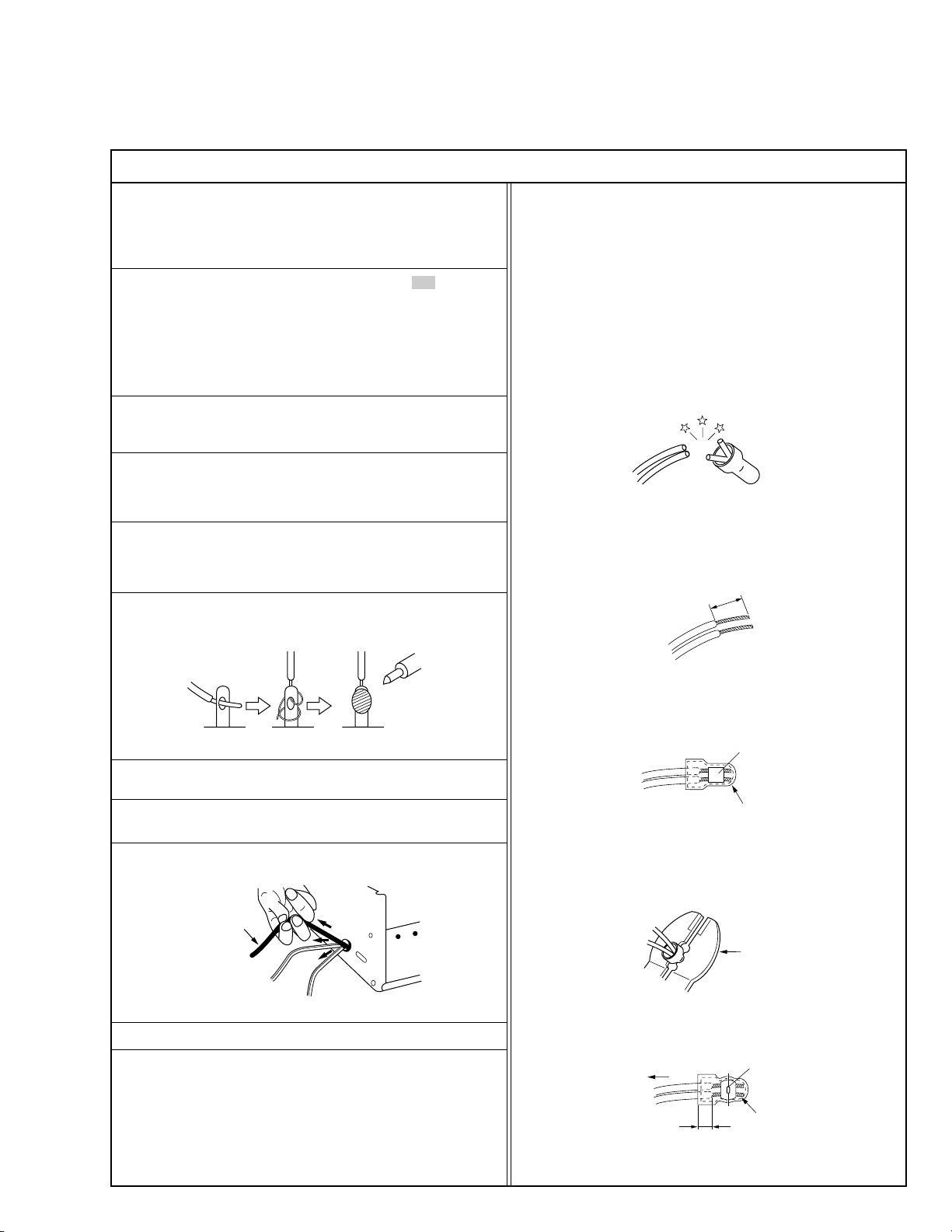
12. Crimp type wire connector
In such cases as when replacing the power transformer in sets
where the connections between the power cord and power transformer primary lead wires are performed using crimp type connectors, if replacing the connectors is unavoidable, in order to prevent
safety hazards, perform carefully and precisely according to the
following steps.
1) Connector part number : E03830-001
2) Required tool : Connector crimping tool of the proper type which
will not damage insulated parts.
3) Replacement procedure
(1) Remove the old connector by cutting the wires at a point
close to the connector.
Important : Do not reuse a connector (discard it).
cut close to connector
Fig.3
(2) Strip about 15 mm of the insulation from the ends of the
wires. If the wires are stranded, twist the strands to avoid
frayed conductors.
15 mm
Fig.4
(3) Align the lengths of the wires to be connected. Insert the
wires fully into the connector.
Fig.1
7. Observe that wires do not contact heat producing parts (heatsinks,
oxide metal film resistors, fusible resistors, etc.)
8. Check that replaced wires do not contact sharp edged or pointed
parts.
9. When a power cord has been replaced, check that 10-15 kg of
force in any direction will not loosen it.
Power cord
Fig.2
10. Also check areas surrounding repaired locations.
11. Products using cathode ray tubes (CRTs)
In regard to such products, the cathode ray tubes themselves, the
high voltage circuits, and related circuits are specified for compliance with recognized codes pertaining to X-ray emission.
Consequently, when servicing these products, replace the cathode ray tubes and other parts with only the specified parts. Under
no circumstances attempt to modify these circuits.
Unauthorized modification can increase the high voltage value and
cause X-ray emission from the cathode ray tube.
I
(4) As shown in Fig.6, use the crimping tool to crimp the metal
sleeve at the center position. Be sure to crimp fully to the
complete closure of the tool.
(5) Check the four points noted in Fig.7.
Not easily pulled free
Wire insulation recessed
more than 4 mm
Metal sleeve
Connector
Fig.5
Fig.6
Crimped at approx. center
of metal sleeve
Conductors extended
Fig.7
S40888-01
Page 5
Safety Check after Servicing
•
Examine the area surrounding the repaired location for damage or deterioration. Observe that screws, parts and wires have been returned
to original positions, Afterwards, perform the following tests and confirm the specified values in order to verify compliance with safety
standards.
1. Insulation resistance test
Confirm the specified insulation resistance or greater between power cord plug prongs and externally exposed parts of the set (RF terminals, antenna terminals, video and audio input and output
terminals, microphone jacks, earphone jacks, etc.). See table 1 below.
2. Dielectric strength test
Confirm specified dielectric strength or greater between power cord plug prongs and exposed accessible parts of the set (RF terminals, antenna terminals, video and audio input and output terminals,
microphone jacks, earphone jacks, etc.). See table 1 below.
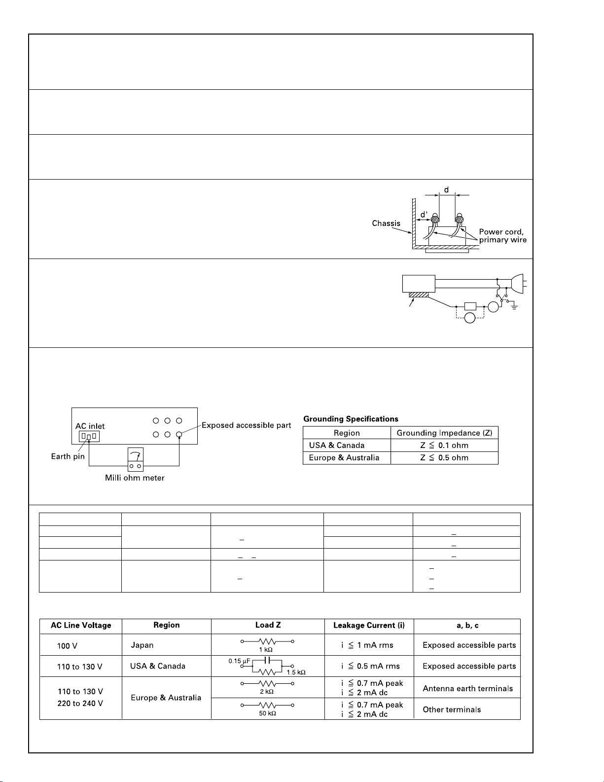
3. Clearance distance
When replacing primary circuit components, confirm specified clearance distance (d), (d’) between soldered terminals, and between terminals and surrounding metallic parts. See table 1
below.
Fig. 8
4. Leakage current test
Confirm specified or lower leakage current between earth ground/power cord plug prongs and
externally exposed accessible parts (RF terminals, antenna terminals, video and audio input and
output terminals, microphone jacks, earphone jacks, etc.).
Measuring Method : (Power ON)
Insert load Z between earth ground/power cord plug prongs and externally exposed accessible
parts. Use an AC voltmeter to measure across both terminals of load Z. See figure 9 and following
table 2.
Externally
exposed
accessible part
Fig. 9
Z
V
ab
A
c
5. Grounding (Class 1 model only)
Confirm specified or lower grounding impedance between earth pin in AC inlet and externally exposed accessible parts (Video in, Video out,
Audio in, Audio out or Fixing screw etc.).
Measuring Method:
Connect milli ohm meter between earth pin in AC inlet and exposed accessible parts. See figure 10 and grounding specifications.
Fig. 10
AC Line Voltage
100 V
100 to 240 V
110 to 130 V
110 to 130 V
200 to 240 V
Region
Japan
USA & Canada
Europe & Australia R 10 MΩ/500 V DC
Insulation Resistance (R)
≤
R 1 MΩ/500 V DC
≥≥
1 MΩ R 12 MΩ/500 V DC
≤
Tab le 1 Specifications for each region
Dielectric Strength
AC 1 kV 1 minute
AC 1.5 kV 1 miute
AC 1 kV 1 minute
AC 3 kV 1 minute
AC 1.5 kV 1 minute
(Class 2)
(Class 1)
Clearance Distance (d), (d')
≤
d, d' 3 mm
≤
d, d' 4 mm
≤
d, d' 3.2 mm
≤
d 4 mm
≤
d' 8 mm (Power cord)
≤
d' 6 mm (Primary wire)
Table 2 Leakage current specifications for each region
Note: These tables are unofficial and for reference only. Be sure to confirm the precise values for your particular country and locality.
II
S40888-01
Page 6

MODEL NAME
The letters and numbers following the model name are used to differentiate between destinations and specifications.
Model name: XID580i - #
1. Detailed specifications
# Portion – Internal option
Nil ......... No option (Standard model)
B...........Equipped with ISO magnetic encorder / IC contact
1
Page 7

HOW TO CONNECT SEPARATELY SOLD PARTS
1. Connecting the Small-type IC Unit
1.
Remove the cover on the side of the printer.
Remove the screw, and then raise the cover to remove it.
2.
Connect the connector.
Please note that the connector has directionality.
3.
Install the unit with three screws.
Install the screws so that the cable of the connector
is not caught.
4.
Install the cover with two screws.
Screw with washer
(provided)
Pass the cable through the notch.
Screw
(provided)
2
Page 8
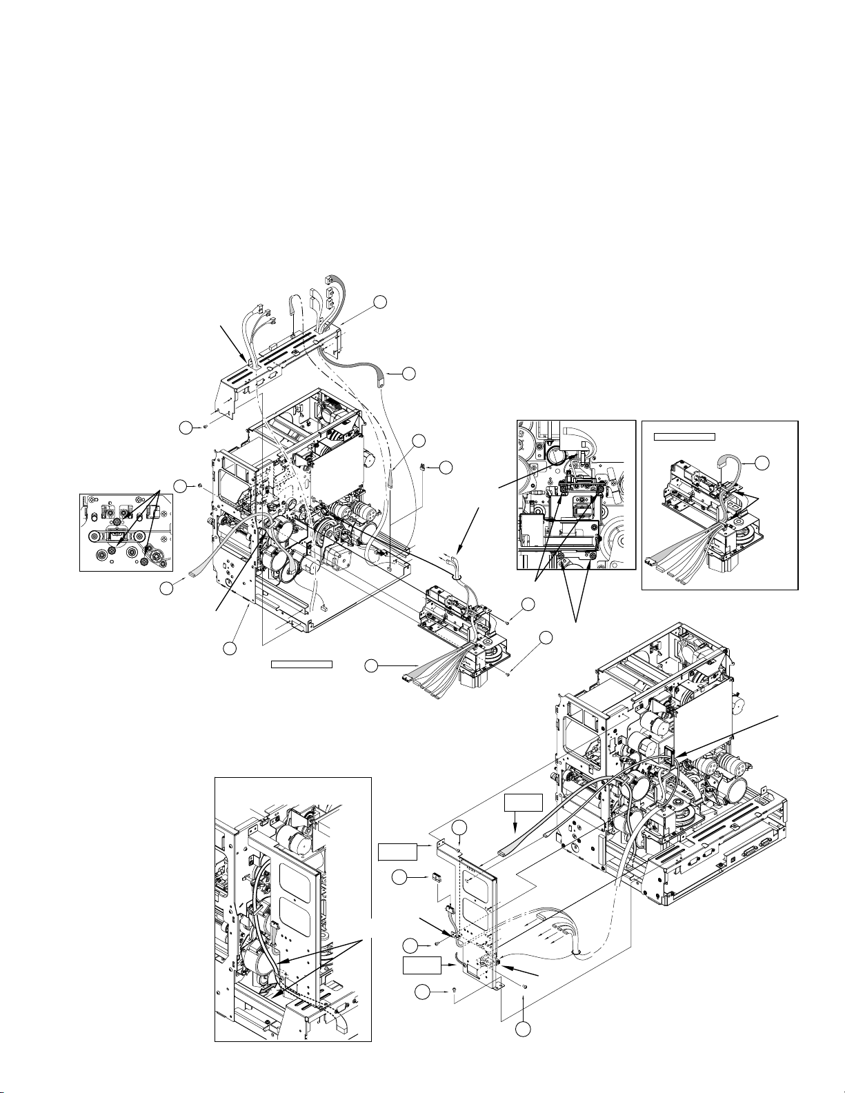
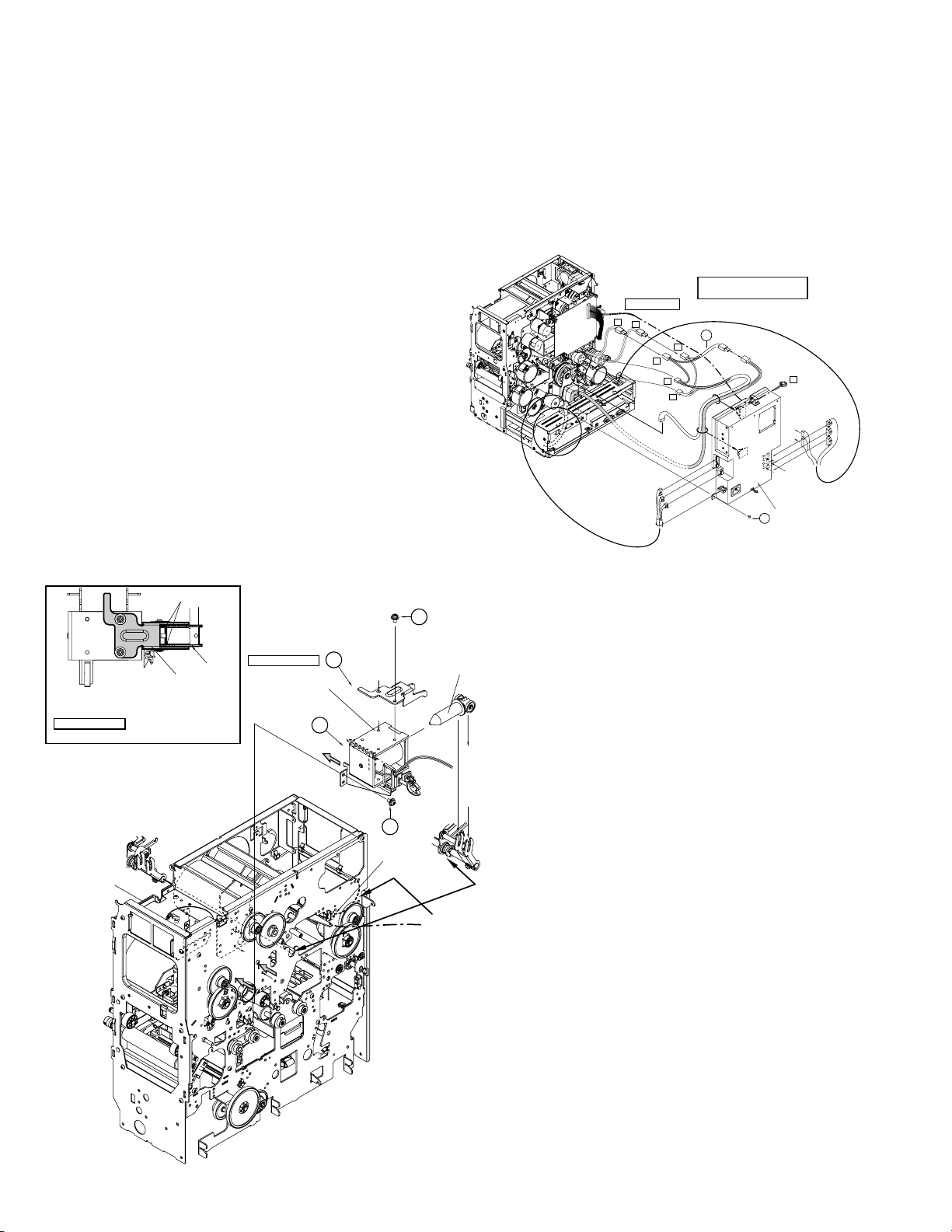
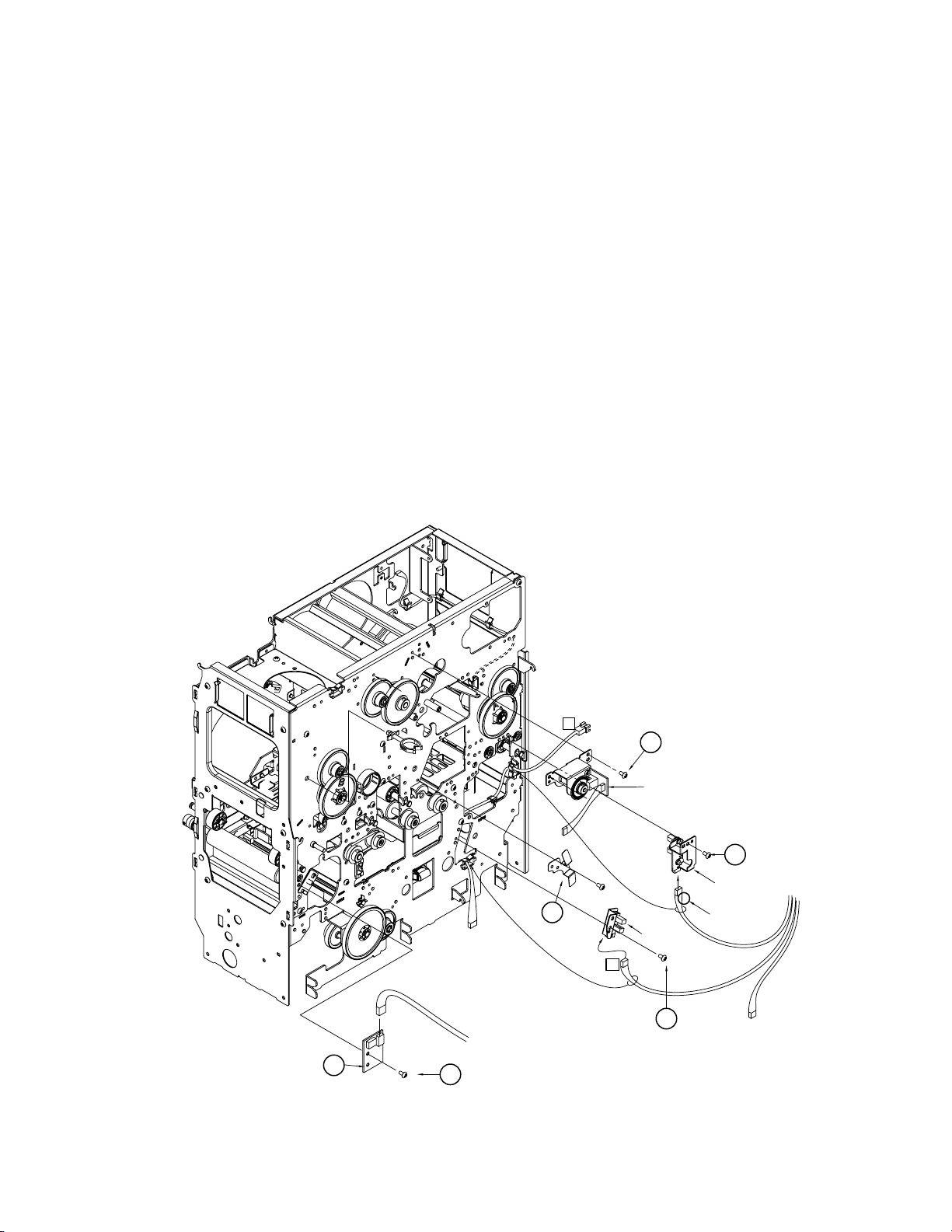
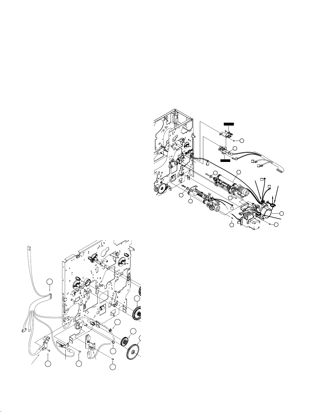
2. Connection of the Magnetic/Contact-type IC Encoder
When the separately sold magnetic/contact-type IC encoder is to be connected to a standard printer, connect it according to the following procedure.
For details in regard to the removal method for each part, refer to “Removal and exchange of the Main Parts”.
1) Remove the top cover.
2) Swing down the power supply.
3) Remove the front panel.
4) Install the magnetic unit. Fix with three black screws 8 at the front and four black screws 8 at the rear.
5) Install the bracket fixing the MG circuit board with four screws 6.
6
Pass the wires of
power switch.
CN3
13
KWS0744-001
KWR18416-001
x6
9
8
12
Clamp
1
(TFA0023)
J10
J9
Explanation drawing 1
J14
(TSA0141)
G.NO.004
Make the cable routed
away from the rail
2
MG PWB SA
Explanation
drawing 1
J10
8
CLAMP
Explanation
drawing 2
14
6
KWS0767-002
15
J14
J10
KWS0768-001
Clamp
6
J1
J8
J7
Explanation
drawing 2
J4
J5
J3
J10
J14
8
8
3pin
CLAMP
Explanation drawing 1
CN12
11
KWR17110-001
Clamp
CLAMP
6
6
3
Page 9
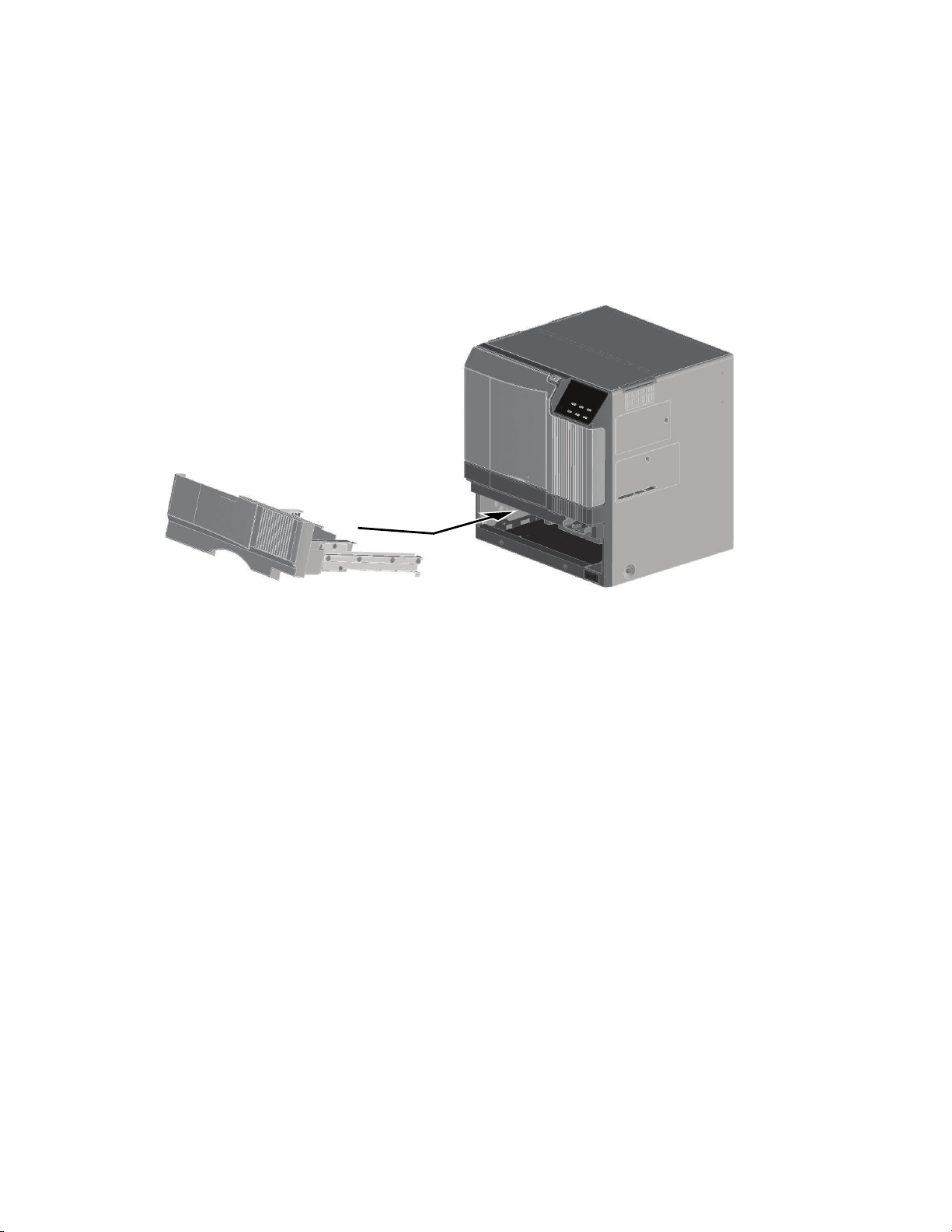
3. Connecting card tray
Upon issuing the card using paper feeding feature on the right, as the NG cards transported to the printer will be ejected,
replace the standard hopper unit with an optional card tray.
Mount the card tray according to the following procedures:
1. Pull out the standard hopper unit diagonally upwards.
2. Insert the optional card tray diagonally downwards.
(Note: The cleaning roller should be left as it is.)
3. Enter the service mode of the printer main unit, select “Card Loading” under the maintenance items and switch from
“standard” to “Right Side”.
4. Settings other than this and operating procedures are dependent to the user system.
Note: If there are 10 cards accumulated continuously in the card tray, the printer will display “Card Tray Full”. Remove
the cards immediately.
5. Keep the removed hopper unit safely.
4
Page 10
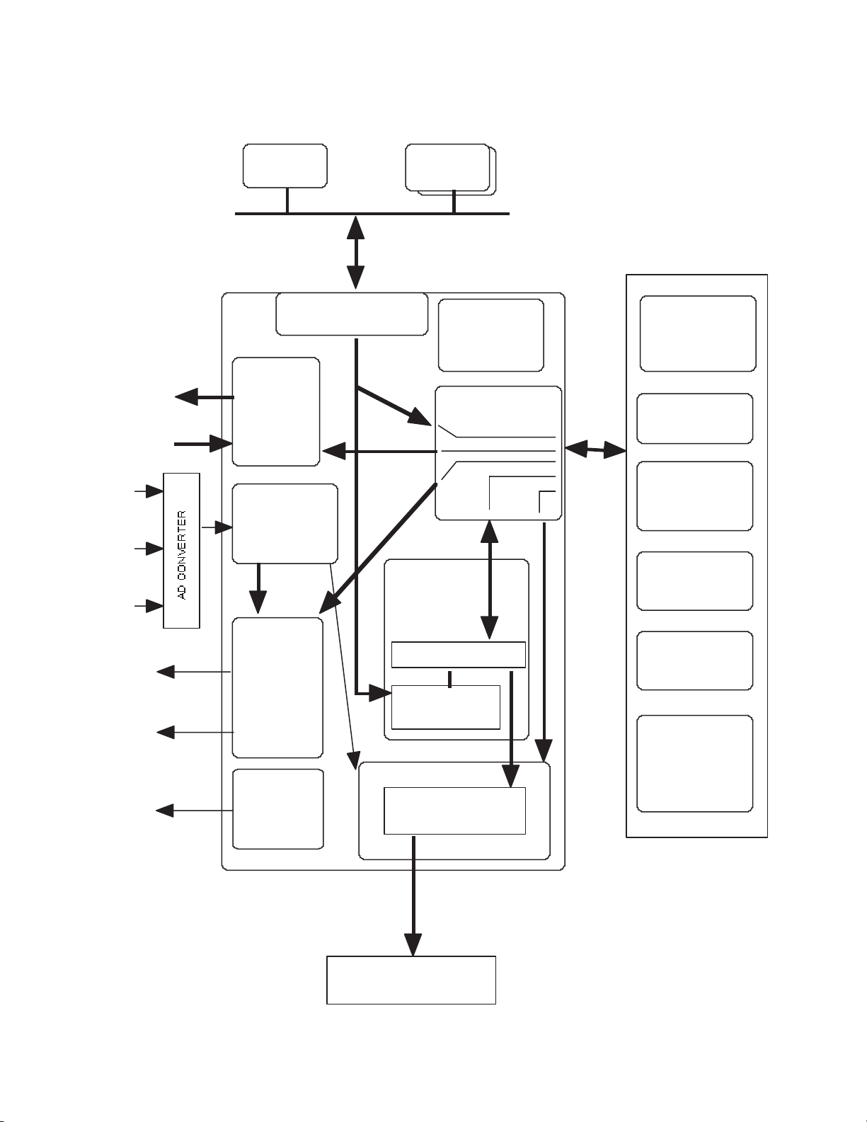
THERMAL HEAD
HEAD
CONN
PWB
U1
EEPROM
32Kbit
HEAD BLOCK
MAIN PWB
FRONT PWB
POWER
SUPPLY
UNIT
U1
CPU
X1
XTAL
66.67MHz
U7
EEPROM
32Kbit
U2
SDRAM
64Mbit
U3
FLASH ROM
16Mbit
TR THERMISTOR
RR
THERMISTOR
DRIVE PWB
NO CARD
CARD IN
CARD (MG POSITION) (PWB)
(OPTION(MGIC))
CARD (TURN) (PWB)
TURN POSITION
EDJE (PWB)
CARD OUT (PWB)
FILM MARK (PWB)
CAM POSITION
TR POSITION
RR POSITION
INK FG (PWB)
CARD NEAR EMPTY
INK FG
(MOTOR built-in)
FILM F G (MOTOR built-in)
SENSORS
U5
SDRAM
64Mbit
U5
FLASH ROM
16Mbit
SENSORS
THERMISTOR &
CONNECTOR (PWB)
EXTERNAL UNIT
HEATER PROTECTOR PWB
USB
I/F
Q13
REGULATOR
(A+5V)
U8
REGULATOR
(3.3V)
Q11
REGULATOR
(1.5V)
U10
REGULATOR
(1.8V)
DC-DC circuit
U11
FPGA
U12
SDRAM
64Mbit
U1
DAConverter
LCD module
(16columX2line)
SWX6
COLOR
LED
LEDX2
BUZZER
U17
USB
chip
X1
XTAL
48MHz
U7
STEP MOTOR DRIVER
Q2
Q3
TRANSISTOR
Q5
TRANSISTOR
Q6
TRANSISTOR
Q7
TRANSISTOR
U8
STEP MOTOR DRIVER
U11
STEP MOTOR DRIVER
U13
DC MOTOR DRIVER
U14
DC MOTOR DRIVER
U15
DC MOTOR DRIVER
SOLENOID (PLATEN ROLLER)
SOLENOID (IC CONTACT(OPTION))
FAN (THERMAL HEAD)
FAN (CARD)
FAN (PRINTER)
CARD MOTOR
FILM MOTOR
CAM MOTOR
FILM MOTOR
INK MOTOR
INK MOTOR
TURN
MOTOR
CARD MOTOR (TURN)
CARD MOTOR (PICK UP )
U9
STEP MOTOR DRIVER
U10
STEP MOTOR DRIVER
U16
DC MOTOR DRIVER
EXTERNAL
UNIT
EXTERNAL
UNIT
MG/IC UNIT(OPTION)
RF-ID UNIT
U14~16
BUFFER
U32,U33
COMPARATOR
U22,36~U39
BUFFER
U2
Serial to Parallel
U19
INVERTER
CPU BUS
U13
ADConverter
U2
RESET IC
(5V)
CLEANING ROLLER INTERLOCK SW
DOOR INTERLOCK SW
CASSETTE INTERLOCK SW
CARD TRAY INTERLOCK SW
FAN (PRINTER)
U7
CLK
DRIVER
X2
XTAL
32MHz
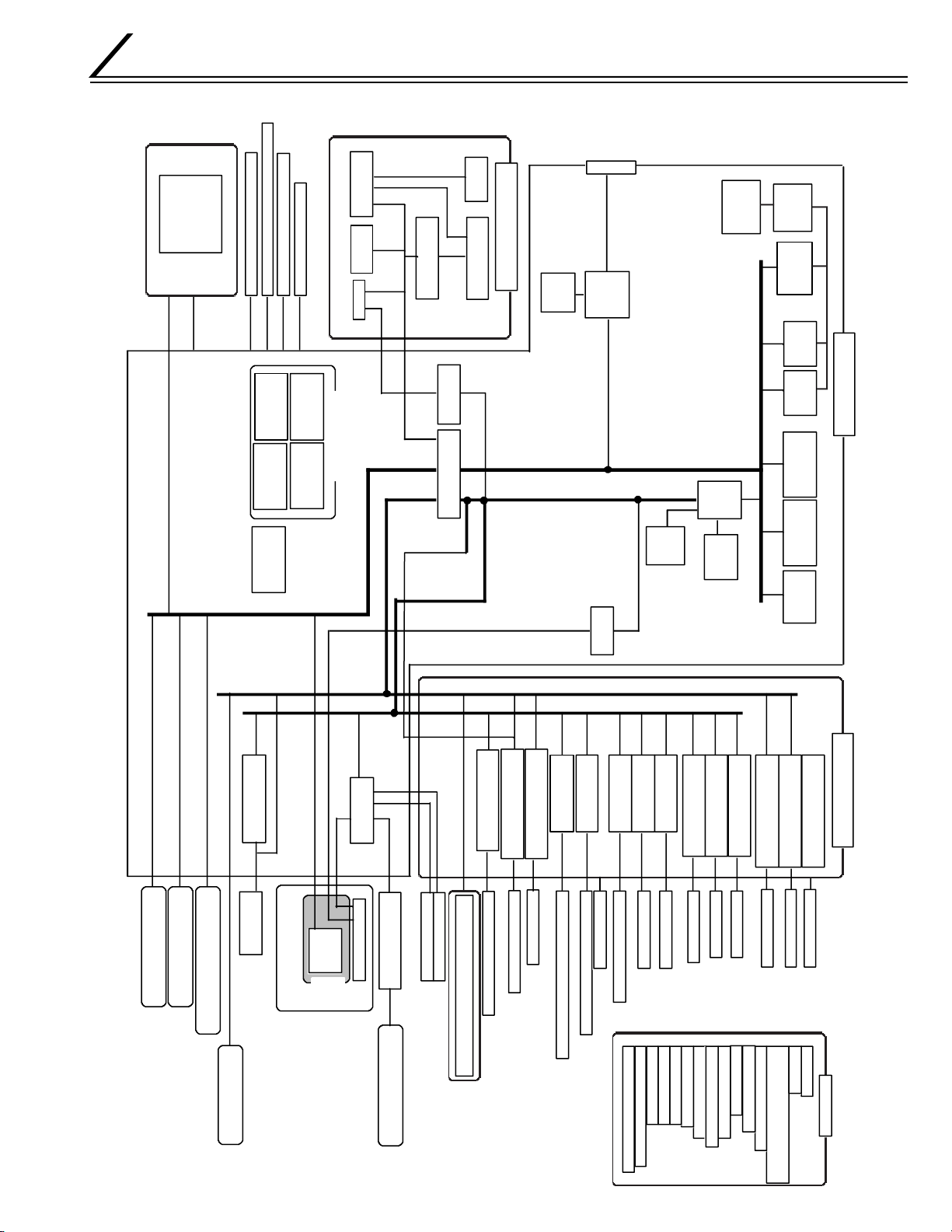
BLOCK DIAGRAM
1. OVERALL BLOCK DIAGRAM
5
Page 11
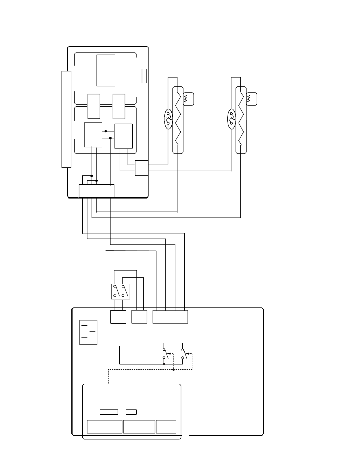
2. BLOCK DIAGRAM OF PRIMARY SIDE OF POWERUNIT
THERMOSTAT
HEATROLLER
(REMEDIAL)
t˚
THERMISTOR
(to DRIVE PWB)
THERMOSTAT
HEATROLLER
(RETRANSFER)
t˚
THERMISTOR
(to DRIVE PWB)
POWER
SUPPLY
UNIT
N(AC IN)
L(AC IN)
SSR2N
SSR2L
SSR1N
SSR1L
CN3
VTH
CN1
5V
12V
CN2
24V
CN8
24V_RC
CN4
CONTROL
SIGNAL
N(AC OUT)
L(AC OUT)
(to ANALOG POWER PWB)
FAIL SIGNAL
(to DRIVE PWB)
HEATER PROTECTOR PWB
POWER
SWITCH
CN1
CN2
AC
VOLTAGE
DETECT
PHOTO
COUPLER
ABNORMAL
CURRENT
DETECT
PHOTO
COUPLER
Primary
Secondary
SSR1L
SSR2L
ON/OFF
CN5
SSR
CN7
CN6
SSR
6
Page 12
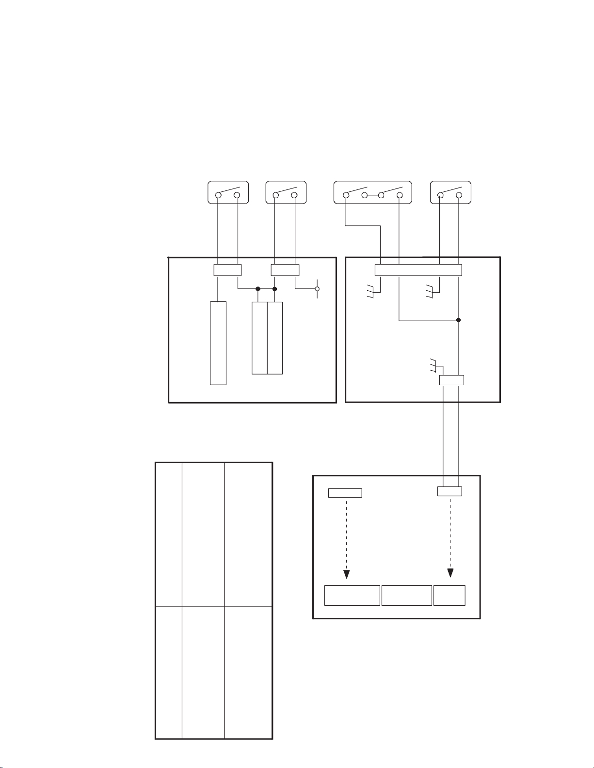
3. INTERLOCK SW BLOCK DIAGRAM
24V
U9
TURN MOTOR DRIVER
U10
CARD MOTOR DRIVER
U16
PICK UP MOTOR DRIVER
Cleaning roller SW (PWB)
Card Tray SW (PWB)
24V_RC
POWER
SUPPLY
UNIT
DRIVE PWB
Cassette SW (PWB)
Door SW (PWB)
J16
J18
J7
J6
CN8
Door SW (PWB) OPEN
and
Cassette SW (PWB) OPEN
24V OFF
Cleaning roller SW (PWB) OPEN
Card Tray SW (PWB) OPEN
Turn Motor STOP
Card Motor STOP
Pick up Motor STOP
Pick up Motor STOP
Specification of Interlock Switch
CN3
Vth
CN1
5V
12V
CN2
24V
CN4
24V_RC
Vth_RC
MAIN PWB
7
Page 13
4.
BLOCK DIAGRAM OF THE FPGA CIRCUMFERENCE ON A MAIN BOARD
Motor
Solenoid
Control
Signals
Sensor input
Retransfer
Heater
Temperature
7
Bend Remedial
Heater
Temperature
8
TPH
Temperature
9
Retransfer
Heater
Control Signal
Bend Remedial
Heater
Control Signal
INK Sensor
LED Driver
CPU
CPU I/F BLOCK
MOTOR
CONTROL
BLOCK
AD
CONVERTER
CONTROL
BLOCK
78
HEATER
CONTROL
BLOCK
(The Heaters
are controlled
by each
temperature.)
D/A
Interface
16bit
Data
6
1
2
PRINT BLOCK
(Temperature
correction,
Outline emphasis,
LUT)
Data Processor
Microcode
Memory(*1)
512Word x 16bit
9
TPH I/F BLOCK
Line Buffer Memory
Flash
Memory
INTERNAL
CLOCK
GENERATOR
SDRAM I/F BLOCK
x 2
32bit CPU BUS
4
56
SDRAM
4MWordx16bit
1
Step Motor
Speed Up/Down
Table
(CPU generates
the table data.)
2
Heater control
Table(*2)
3
16bit
Data
3
TPH Control
Table(*2)
(Strobe)
4
Tables for
Print Data
Correction(*2)
5
Work Memory
for PRINT BLOCK
6
Plane Memory
2MByte
(*1)(*2)These data are copied
Print Data
Strobe
Lutch
Thermal Print Head
from Flash Memory.
*FPGA=
FieldPrgrambleGateArray
8
Page 14
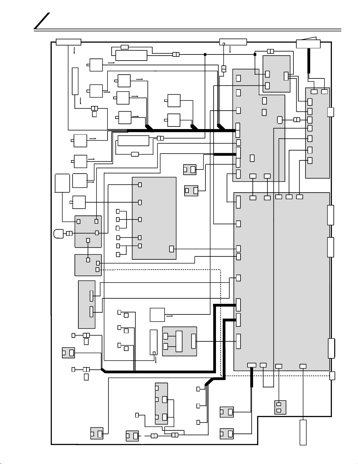
WIRING DIAGRAM
USB I/F
POWER SUPPLY
DRIVE PWB
Option1 I/FOption2 I/F Serial I/F
AC IN
DC5/12V
FRONT PWB
CTL1 V TH
HEAD PWB
MAIN PWB
CTL2ACAC
KWS0644-001
Step
Motor
Step
Motor
DC
Motor
CN8 CN9
Step
Motor
DC Motor
DC Motor
DC Motor
Step
Motor
OPTION
(MG/IC Block)
Step
Motor
S3
S1
S2
T2
F1
T1
Pick up motor
Turn over motor
Turnover feed
motor
Ink takeup
motor
Ink supply motor
INK FG
sensor
card supply sensor
Platen
roller
solenoid
Card edge
sensor
HEATER
PROTECTOR
PWB
CN1 CN2
KWR16003-001
Turnover
card sensor
Retranfer
film mark
sensor
No card
sensor
Turnover
initial position
sensor
Card near
empty sensor
Thermal Head
cooling fan
Thermostat
Retransfer film
Take up motor
Cam motor
Card feed
motor
Retransfer film
supply motor
Remedial
Heat Roller
Thermistor
Card outlet
sencer
Retransfer
Heat Roller
Thermistor
Cam sensor Retransfer
Heatroller
Positionning sensor
Card tray
interlock
Thermal Head
Cleanning roller
interlock
Door interlock Cassette
interlock
Ink start
position
sensor
Cooling fan
AC
AC
Cooling fan
POWER
SWITCH
Remedial
Heat roller
Retransfer
Heat roller
Thermostat
DC24V
DC5/12V/24V
Step
Motor
MG Feed Motor
IC CONTACT
Solenoid For
Head position1
Card position
210Encode
75Encode
IC FLAG
5V 12V
IC R/W
MG HEAD
IC
CONTACT
XID580i BLOCK DIAGRAM
Head position2
Head position3
Remedial
Heatroller
Positionning sensor
Card Cooling Fan
J6
J7
J4
J8
J13
J12
J11
J24
J23
J10
J9 J15
J5
J21
J22
J2
J18
J16
J17
J14
RF-ID PWB
J9
J8
J11
J12 J16
J14
J7 J6
J3
J4
J2
J1
CN1
CN2 CN3
to J13
J13 J15
J10
J9
J12
to
J16
to J9
to J12
to J8
to J13
to J13
to
J8
to J16
to J10
J1
to J11
CN1
CN1
CN3
to J15
CN3
CN301
CN1
CN201
CN4 CN5
CN6
CN7
to J8
CN2
9
Page 15
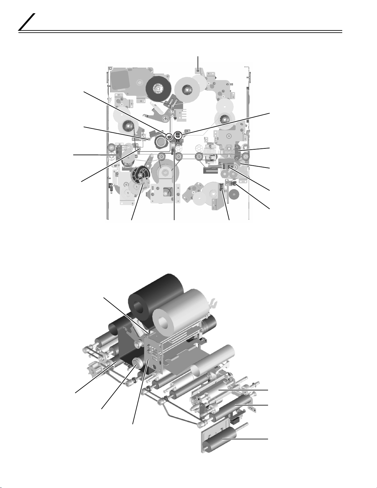
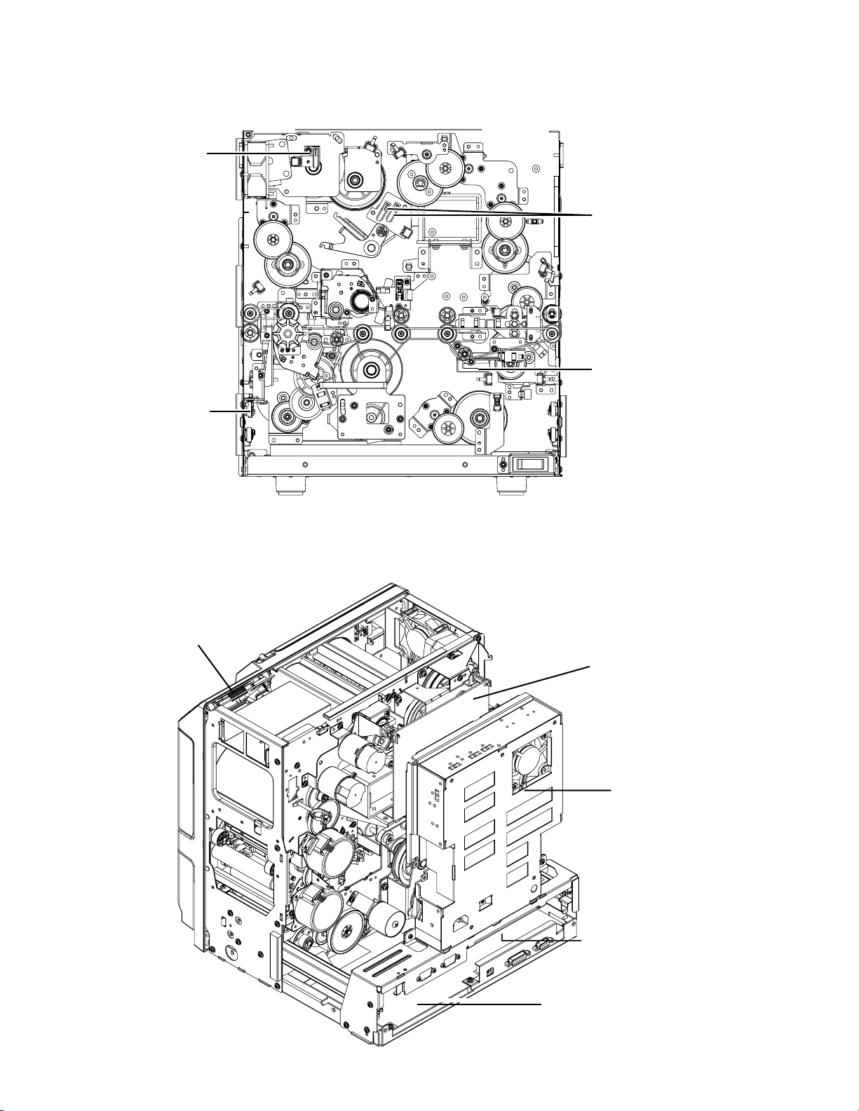
Main Parts Layout
1. Sensors
Retransfer film
mark sensor
(circuit board)
Retransfer roller
sensor
Card outlet
sensor
Bend remedial
roller sensor
Ink FG sensor (encorder circuit board)
Ink start position
sensor (circuit board)
Turnover card
sensor (circuit board)
Turnover initial position
sensor
Card supply sensor
Cam sensor Card near empty sensor
2. Thermal Head and Rollers
Platen roller
No card
Card edgesensor
(Circuit board)
10
Bend remedial roller
Retransfer roller
Turnover unit
NG card
outlet roller
Thermal head
Card supply roller
Page 16
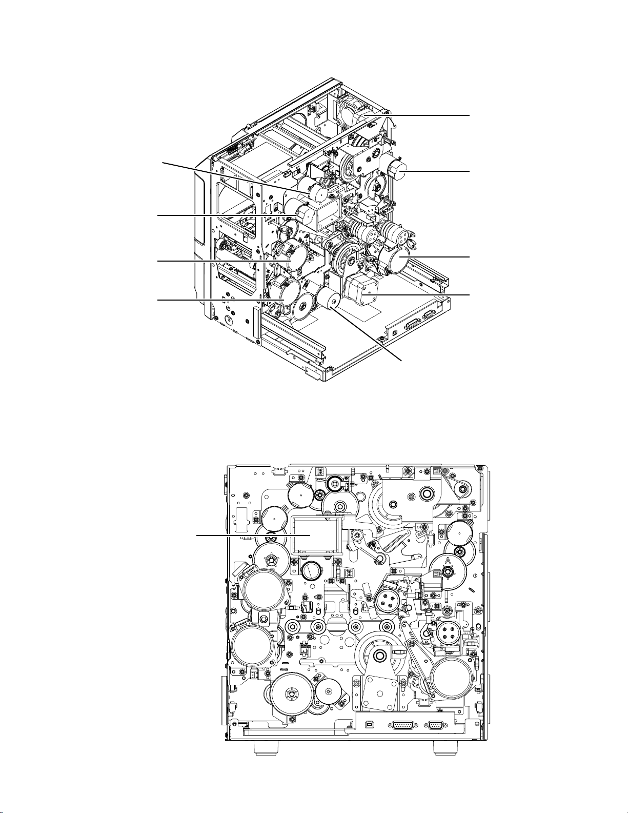
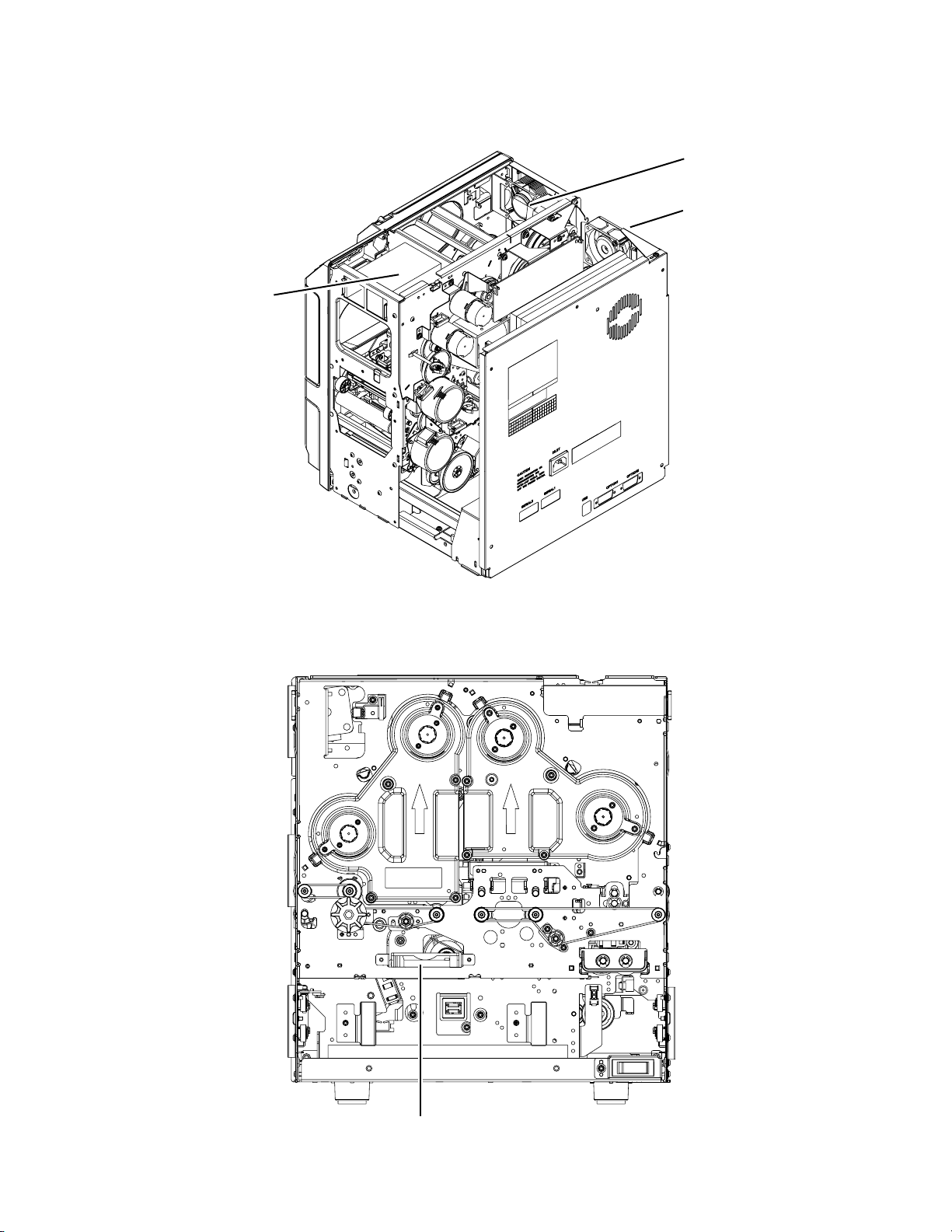
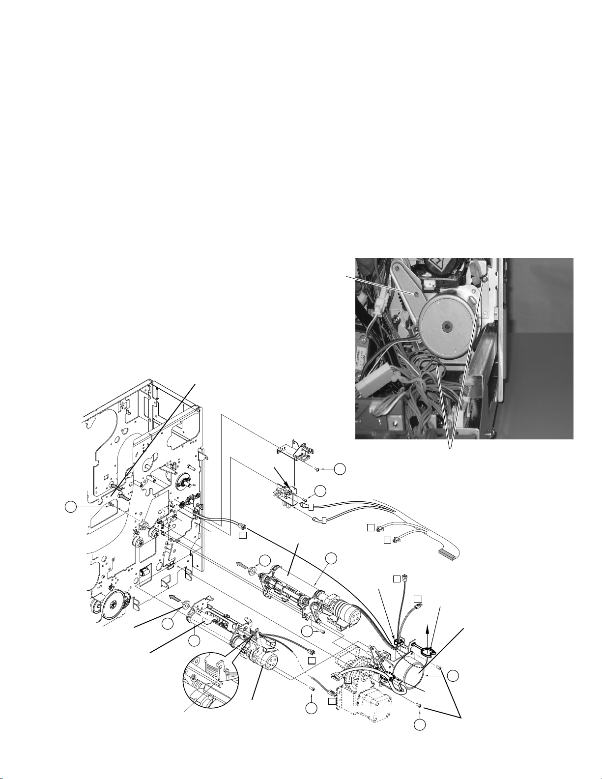
3. Motors
Ink take-up
motor
Ink supply
Motor
Retransfer
film supply
motor
Retransfer
film take-up
motor
Turn over
motor
Turn over
feed motor
4. Solenoid
Platen Solenoid
Cam motor
Card feed
motor
Card pick up motor
Rear veiw
11
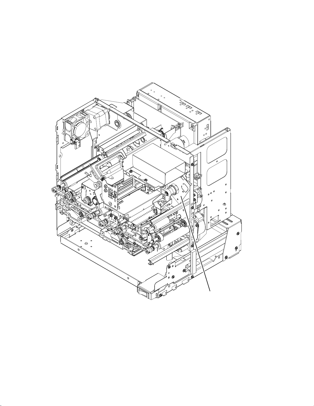
Page 17
5. Switches
Door interlock
switch
Card tray
interlock switch
Cassette interlock
switch
Cleanning roller
interlock switch
6. Circuit Boards, Power Supply Unit, and Fans
Front PWB
Drive PWB
Power
supply unit
Heater protector
PWB
12
MAIN PWB
Page 18
Thermal head
cooling fan
Ventilation fan
Ventilation fan
Card cooling fan
13
Page 19
7. RF-ID
14
RF-ID unit
Page 20
Screw B
Screw A
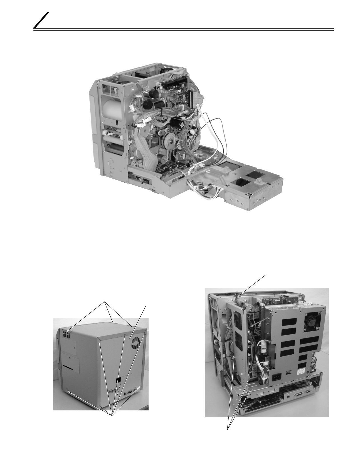
REMOVAL AND EXCHANGE OF THE MAIN PARTS
1. CHECKING AT THE TIME OF SERVICING
When confirming the symptoms, swing the power supply unit down as shown in the following figure and check the inside.
1.1 REMOVE THE TOP COVER AND THE
REAR PANEL.
1) Remove the filters on both sides of the top cover.
Caution: If they are not removed, the filters will be
damaged when the top cover is moved.
2) Remove the seven screws A and pull the top cover
to the rear to remove it.
3) Remove the screw B and take off the rear panel.
Filter
ScrewB
1.2 REMOVE THE MG CIRCUIT BOARD.
1) Remove the three screws A and the screw B.
2) After the power supply unit has been swung down,
use the screw B for provisional fixing, so that the
MG circuit board does not move.
ScrewA
15
Page 21

1.3 SWING DOWN THE POWER SUPPLY UNIT.
1) Remove the two screws B on both sides.
2) Loosen the four screws A on both sides.
3) Raise the power supply unit and swing it down.
4) Remove the thermostat cable from the clamper, raise
the power supply unit once, and then swing it down.
Power supply unit
Screw B
Screw A
2. REMOVAL AND EXCHANGE
OF THE MAIN PARTS
2.1 REMOVAL OF THE HEAT ROLLER
CAUTION:
Immediately after the power has been switched OFF,
the retransfer roller and the bend remedial roller are
still hot.
Please perform the work after these rollers have
cooled down sufficiently, as otherwise burns may
be caused.
Screw A Thermostat wire
Thermistor wirePower connector
2.1.2 Removal of the Retransfer Roller
1) Disconnect the right side of the spring.
2) Remove the screw A and bring the sensor bracket
to free condition.
For installation, match the notches so that they engage.
3) Disconnect the junction connectors of the thermistor and the thermostat of the retransfer roller.
Remove the power connector.
4) Remove the two screws B and remove the roller by
pulling it slowly to the front.
Notch Spring
Screw A
1) Refer to section 2.2 and remove the cam motor.
2) Remove each roller individually.
2.1.1 Removal of the Bend Remedial Roller
1) Disconnect the junction connectors of the thermistor and the thermostat of the bend remedial roller.
Remove the power connector.
2) Remove the two screws A.
3) The bend remedial roller can be removed when the
roller is turned upwards and slowly pulled to the front.
16
Screw BPower connector
Page 22
CAUTIONS FOR INSTALLATION AND
CLEANING OF BOTH ROLLERS
1) The oil bearing % is on the tip of the roller assembly.
Do not forget it at the time of installation and removal.
2) When installing a new roller, take care that it will not
hit the bracket.
3) AC 100 V is impressed to this heater. Use sufficient
care for the wire processing.
4) Do not turn the roller by hand. The thermistor may
become damaged when the roller is turned by hand.
Accordingly, when a roller is to be turned for
cleaning etc., do the turning while the bracket
on which the thermistor is installed has been
raised a little.
2.2 REMOVAL OF THE CAM MOTOR
1) Remove the two screws A.
Please use a long screwdriver for the lower screw.
If the power supply unit is in the way, raise it once
and use the gap underneath to perform the work.
2) Remove the screw B from front side.
Refer to section 2.9 to remove the front panel.
3) Insert the screwdriver to the hole fixing the card cooling fan, and remove another screw B.
(Refer to section 2.14.3)
4) Disconnect the flat wire and the other cables.
5) Raise the bend remedial roller and pull out the motor, taking care that the motor bracket will not hit
circuit boards etc.
Screw B
(Front side)
18
QYSPSPD
4008N
Bearing
Thermistor bracket
Pass the wires
behind the lever
15
(-010)
screw B
1
(TSS0181)
Clamp
F1
(-010)
15
Retransfer roller
17
KJJ46271-003
17
A
B
Bend remedial roller
(TSS0182)
3
12
KJJ46271
-003x2
T1
H1
17
KJJ46271
-003x2
KJJ46271-003
T1
Clamp
(T2,H2)
P4
(FD M.MOTOR ASY)
Screw A
T2
T2
Clamp
H2
(F1)
Cam motor
5
(TSS0189)
Clamp
(P4)
17
KJJ46271
-003x2
Screw A
17
Page 23
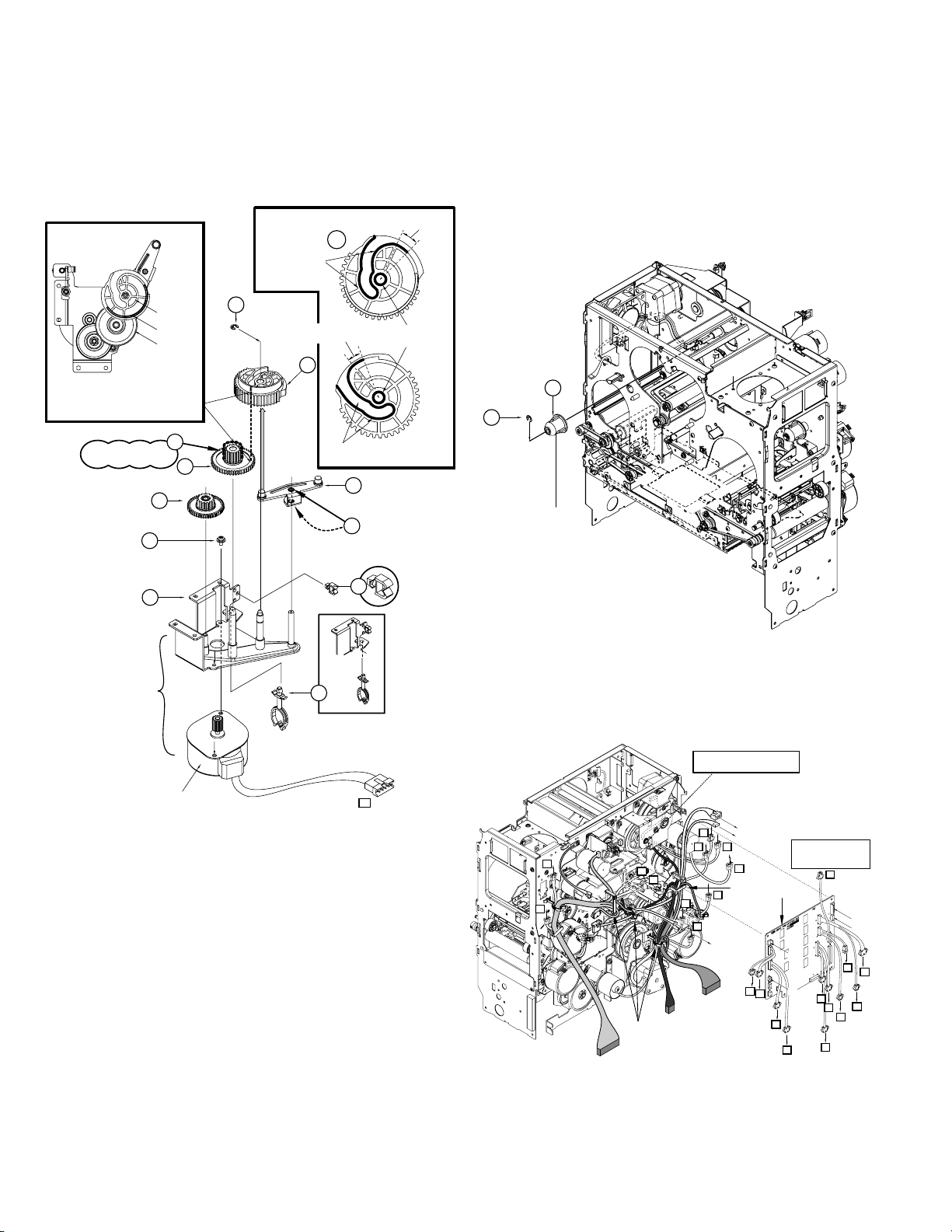
2.2.1 Installation of the Cam Motor
1) The gear of the cam motor has a phase. When it is
removed at the time of roller cleaning, exchange,
etc., it can be installed again in the same condition,
but setting in the following way should be done when
the cam gear is exchanged.
Apply grease to this side also
20
Apply grease to
this side also
12
Apply grease to this side also
13
20
Apply sufficient grease
to the hole for the shaft.
Please use care, as the
installation orientation
can be mistaken easily.
Apply a sufficient quantity
of grease to the two
holes for the shaft.
Install so that the slit of the
cam gear comes to the gear
edge of the double gear
when seen from above.
Gear setting method
Apply grease to a small
gear by one grain of rice.
QYSPSPD3006Nx2
Cam gear
Slit
Double gear
9
7
Apply grease to
this side also
14
QYREE4000X
Engage with
20
10
the cam gear.
Upper
side
Lower
side
2.3 REMOVAL OF THE RETRANSFER FILM
SUPPLY MOTOR
1) Remove the ink ribbon and the retransfer film cassette.
2) Remove the bobbin holder 7 on the film supply side.
Perform the work while using your hand to prevent
that the E-ring drops down.
7
QYREE4000X
8
Bobbin holder
17
18
P4
Cam motor
Before installing the gear,
install it on the bracket.
6
Stepping motor SA
2) When installing the cam motor, first insert the longest shaft into the hole while raising the bend remedial roller a little.
Next, insert the second shaft into its hole while turning the motor bracket a little. The bend remedial roller
will move down.
Finally, confirm that the projecting part is in the heater
lever hole.
At this time, raise the bend remedial roller by hand,
confirm that it is locked, and tighten the screws.
3) Check the cam movement as described in Service
mode "Diag. TEST cam motor".
3) Remove the drive circuit board.
Disengage the clampers and the connector.
Disengage the two clampers fixing the circuit board
and remove the circuit board by pulling it in diagonal
direction.
DRIVE PWB is attached after checking
that the wire passes along 3set in EDGE
SADDLE
(Front sensor)
J7
F2
J6
P3
F1
J11
(KWS0751-002)
(Tray interlock)
D3
Clamp
D1
P5
P1
P2
J5
D1
Clampx3
(KWS0757-002)
D2
D4
P4
(Door interlockSA)
DRIVE PWB SA
D2
P1
The relay connector confirms
and connects with number as
which the connector number
is same.
J5
J11
P2
F3
J7
J6
F2
D3
P5
D4
P3
F1
P4
18
4) Remove the tensioning spring @ .
(Refer to the figure on the lower part of next page.)
5) When the five screws
are removed, the film
&, (
supply motor assembly can be removed.
(Refer to the figure on the lower part of next page.)
Page 24
2.3.1 Installation of the Retransfer Film Supply Motor
(TSS0187)
5
18
D3
11
12
17
QYSPSPD4008Nx2
(-007)
P3
19
19
QYSPSPD4008Nx3
Retransfer film supply motor
Tighten provisionally.
KJJ46271
-003x2
Clanp
Clanp
Retransfer film take up motor
20
1) When the motor has been disassembled or exchanged, first the belt @ tension must be adjusted.
2) After assembly has been performed, leave the screw
tightened provisionally.
#
3) Turn the motor all the way in arrow direction and
tighten the screw # securely.
Tighten the screw B securely to turn the
motor in arrow direction to tighten the belt,
and then tighten the screw A securely.
Tighten provisionally.
7
F689ZZ
4) When installing the motor assembly, the tension adjustment of another belt % is required.
5) Install the two screws &.
6) Tighten the four screws
7) Hook the tension spring @.
8) Tighten the four screws securely.
9) Install the bobbin holder.
(, )
provisionally.
QYSPSPD3006Nx2
13
11
15
80S2M224
A
B
F689ZZ
11
QYSBST3006Nx2
14
10
15
80S2M224
8
19
Page 25
2.4 REMOVAL OF THE RETRANSFER FILM
TAKE UP FILM WINDING MOTOR
With the drive circuit board removed, the Retransfer film
take up motor can be removed after the screw * in the
above figure has been removed. (Refer to a front page.)
Ink supply motor
Ink take-up motor
KJJ46271-001x2
18
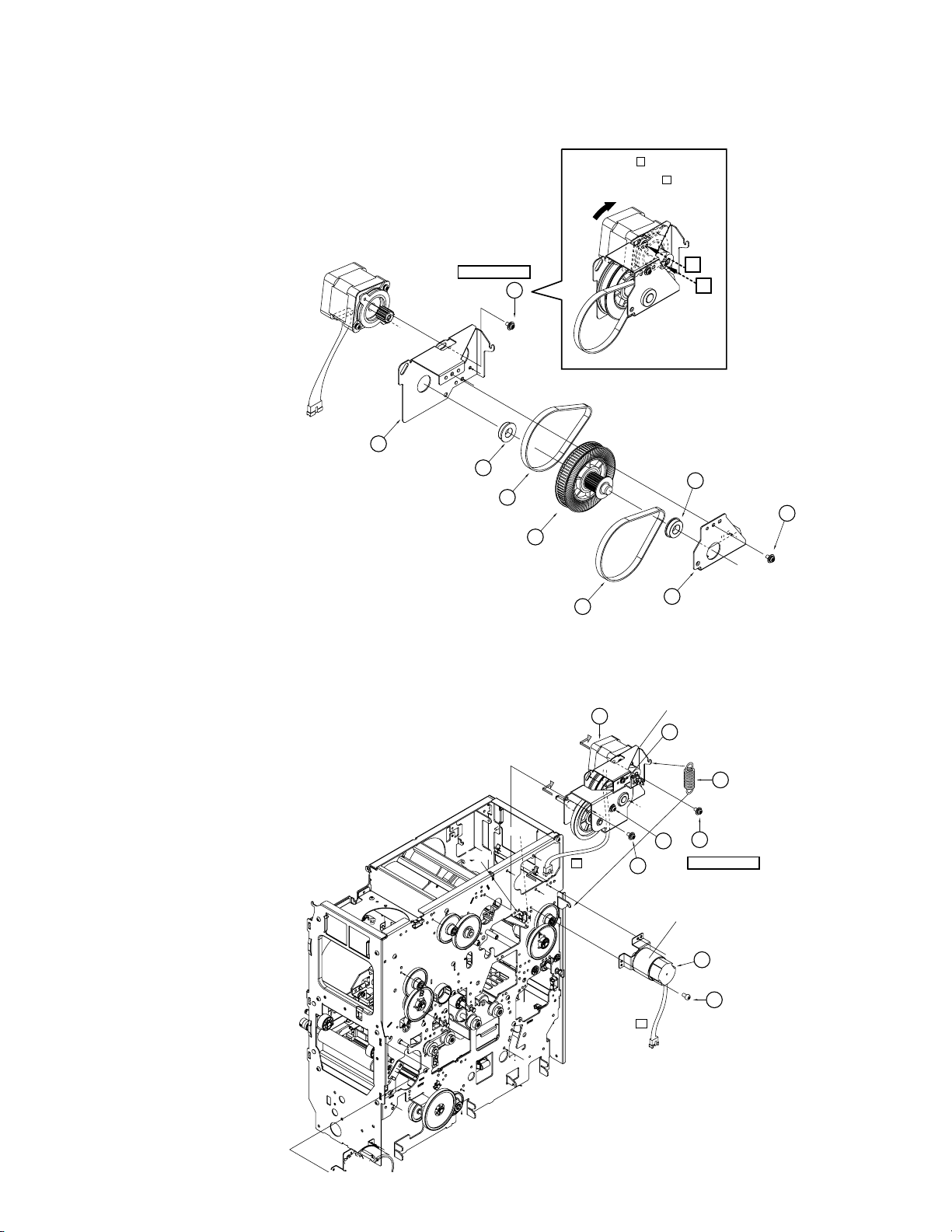
2.5 REMOVAL OF THE CARD FEED MOTOR
1) Remove the tensioning spring
2) Remove the two screws (. Disengage the belt from
the roller.
3) The card feed motor can be removed by pulling it to
the front.
2.5.1 Installation of the Card Feed Motor
1) When the motor has been disassembled or exchanged, first the belt tension must be adjusted.
2) After assembly has been performed, leave the screw
tightened provisionally.
8
3) Turn the motor all the way in arrow direction and
tighten the screw 8 securely.
4) Engage the belt and tighten the screw ( provisionally.
5) Apply the tensioning spring %.
6) Securely tighten the screws ( which have been tightened provisionally.
QYSBST3006Zx2
8
%.
7
P1 P2
D1
D2
3
Turnover card feed motor
Turnover motor
KJJ46271
20
-001x3
Clamp
Clamp
Set the belt
to the pulley.
P5
Card feed motor
Tighten provisionally
DPSP4008Nx2
Set the springs to tighten the belt,
and then tighten securely.
(-006)
15
19
11
12
(M180)
13
(M224)
Tighten the screw B securely to turn
the motor in arrow direction to tighten
10
11
15
Tighten provisionally
DPSP3006Nx2
16
Motor SA
the belt, and then tighten the screw A
securely.
A
B
20
Page 26

2.6 REMOVAL OF THE INK SUPPLY MOTOR AND THE INK TAKE-UP MOTOR
2.9 REMOVAL OF THE FRONT PANEL
1) When there is an MG circuit board, remove the circuit board screws and move the circuit board to the
side.
2) Disengage the hook on the left side of the drive circuit board. Disengage the wire clamp.
3) The ink motor assembly can be removed after the
two screws * have been removed. (Refer to a front
page.)
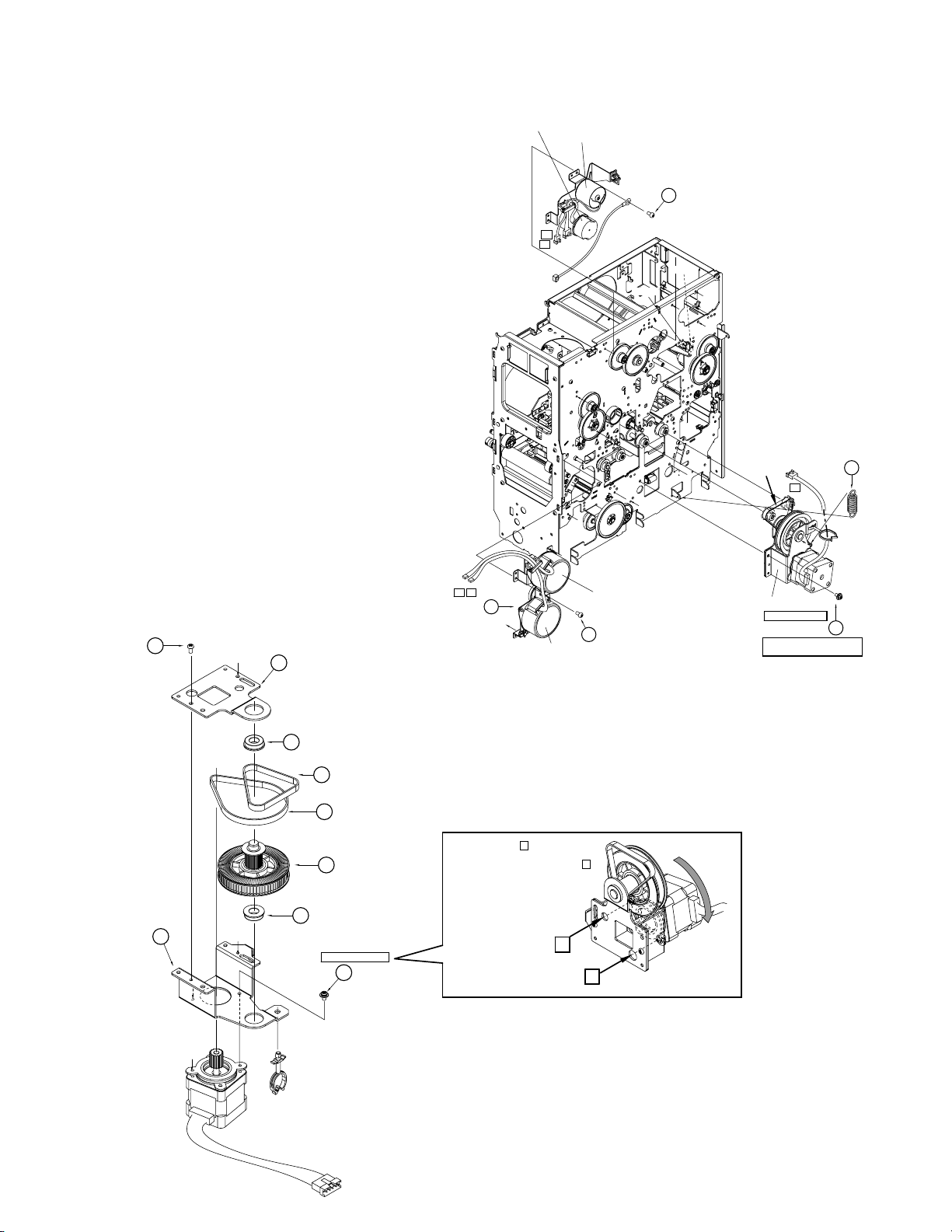
2.7 REMOVAL OF THE TURNOVER MOTOR
AND THE TURNOVER CARD FEED
MOTOR
1) The turn over motor and the turn over card feed
motor assembly can be removed after the three
screws ) have been removed. (Refer to a front
page.)
Remove the spring, as one of the screws is hidden
by the spring.
2.8 REMOVAL OF THE CARD PICKUP
MOTOR
1) Remove the retransfer film and the ink ribbon cassette.
2) Remove the card tray.
3) Remove the cleaning unit.
4) When the six screws
and the screw 5 for earth
4
wire have been removed, the front panel can be removed.
Installation of the Front Panel
1) There are two claws at the rear of the front panel.
Insert into the frame by lightly hitting on the claws.
And then secure the six screws 4.
Front Panel
5
1) The card pickup motor assembly can be removed
after the two screws * have been removed.
Insert the gear shaft
Card pikup motor
18
KJJ46271
-001x2
Insert the front panel
into the frame by lightly
hitting on the claws.
M
G
IS
O
I
C
4
SDSP4008Nx6
21
Page 27
2.10 REMOVAL OF THE PLATEN SOLENOID
100V/200VCommon
H1
H2
CN8
CN4
CN5
CN6
CN7
CN8
CN4
CN2
CN1
CN3
H1
H2
6
KWS0639-001
POWER SUPPLY SA
F3
H1
H2
10
KJJ46271-003x2
H1=Retransfer heater
H2=Bend Remedial heater
1) Remove the drive circuit board.
2) Disengage the wire from the clamp. (2 places)
3) Remove the two screws
and then remove the so-
(
lenoid support @ and #.
4) Remove the two screws
, raise the solenoid body
&
once, and pull it to the rear.
5) Be careful not to damage the disk of ink encoder
located above when removing the screw
(
.
2.10.1 Installation of the Platen Solenoid
1) Insert the plunger by itself into the cutout.
2) Fix the solenoid body with two screws
&
.
3) Fix the solenoid support with two screws (. At this
time, Pay attention to the following item.
4) Before tightening the screws, adjust the gap uniformly so that there will be no interference with the
platen lever and the solenoid support when the
plunger moves in and out.
5) Be careful not to damage the disk of ink encoder
located above when securing the screw (.
2.11
REMOVAL OF THE POWER SUPPLY UNIT
1) Disconnect the wires and the connectors.
2) Remove the two screws
0
.
3) When ordering a power supply unit, also order the
wire clamps around it at the same time.
Gap
Platen lever
Before tightening the screws, adjust the gap uniformly so
that there will be no interference with the platen lever and
the solenoid support when the plunger moves in and out.
Explanation drawing 1
Caution for the time of installation of the solenoid support
Solenoid support
22
Explanation drawing 1
Platen solenoid
(TSS0179)
11
QYSPSPD4008Nx2
19
12
QYSPSPD
17
4008Nx2
Clamp
Plunger
Engage the bearing with
the rear frame.
Lead the wire along the
bracket so that it does not
become an obstacle on the
inside of the bracket.
Page 28
2.12 REMOVAL OF SENSORS AND SWITCHES
2.12.1 Removal of the Cam Sensor
Function
This sensor decides the origin position for pressurizing
the retransfer roller and the bend remedial roller.
1) Refer to section 2.2 and remove the cam motor.
2) The sensor can be removed after the screw * has
been removed.
2.12.2 Removal of the Card Outlet Sensor
Function
This sensor detects card jams. An error will be caused
when no card passes the sensor within a fixed time after completion of retransfer.
1) The sensor can be removed after the screw ( has
been removed.
2.12.3 Removal of the Ink Encoder Circuit Board
Function
The ink feed quantity is decided by the pulses of this
encoder. Start position is decided by the ink start position sensor.
1) The bracket can be removed after the two screws
have been removed.
2.12.4 Removal of the External Unit Power Circuit
Board
Function
When a small external IC unit is connected, power is
supplied from this power supply.
The thermistor detecting the environment temperature
is installed on this board.
1) Refer to section 2.2 and remove the cam motor.
2) The circuit board can be removed after the screw
has been removed.
)
⁄
EXT. unit power
F1
11
S3
7
KJJ46271-003
21
KJJ46271
20
-003x2
Ink Encoder
Cam sensor
18
KJJ46271
-003
19
KJJ46271-003
Card outlet
sensor
Yellow
23
Page 29
2.12.5 Removal of the Turnover Initial Position
1
sensor
2.12.8 Removal of the Retransfer roller/Remedial
Roller Sensor
Function
This sensor decides the origin position for the turn unit.
1) Refer to section 2.7 and remove the turnover and
card feed motor.
2) The sensor can be removed after the screw
&
been removed.
2.12.6 Removal of the Card Near-empty Sensor
Function
When the number of remaining cards drops to about 20
cards (for the card 0,76mm thick) , the electronic buzzer
sounds.
1) Refer to section 2.16.1 and remove the Main circuit
board.
2) Remove the card tray.
3) The sensor can be removed after the screw ( has
been removed with a long screwdriver from the hole
in which the Main circuit board is located.
2.12.7 Removal of the No Card Sensor
This sensor checks whether there are remaining cards
or not. An error is caused when the remaining quantity
becomes zero.
1) Refer to section 2.7 and remove the turnover and
card feed motor.
2) The sensor can be removed after the screw * has
been removed.
has
Function
This sensor detects the origin of the retransfer roller and
the bend remedial roller.
Energization is performed only when a roller is in this
position.
1) Remove the screw &.
2) Slide the sensor to the side, as the lever is inserted
into the sensor.
DR PCB BKT SA
TSS0239-V
17
17
A
B
(-010)
TSS0239-U
HEATER SENSOR SA
F1
(-010)
15
15
1
(TSS0181)
(TSS0182)
12
T1
17
3
H1
T1
CLAMP
(T2,H2)
P4
(FD M.MOTOR ASY)
T2
T2
CLAMP
(F1)
H2
(TSS0189)
5
CLAMP
(P4)
17
Head cooling fan
Turnover initial
position sensor
24
KWS0757-002
15
17
KJJ46271
-003
No Card
sensor
Card near-empty
18
sensor
KJJ46271
-003
11
11
19
1
12
KJJ46271-003
Page 30

2.12.9 Removal of the Retransfer Film Mark/Ink
Start Position Sensor Circuit Board and the
Card Edge Sensor
Function
Card edge sensor
•
This sensor decides the card position at the time of
card retransfer.
Retransfer Film mark sensor
•
This sensor detects the black bar on the film and
selects the panel for printing.
Ink start position sensor
•
This sensor detects the boundary between magenta
and cyan ink. Next, the pulses of the rotary encoder
are detected and movement is made to yellow.
1) When a magnetic encoder is built-in, refer to "Connection of optional parts" and remove the encoder.
2.12.10 Removal of the C.L. Interlock Circuit Board
and the Card Supply Sensor
Function
C.L. interlock switch
•
This sensor detects the presence or absence of the
cleaning unit.
When the switch is OFF, no power is supplied to the
driver IC for the card supply motor and the turnover
motor.
Card supply sensor
•
This sensor checks whether cards are being supplied or not.
1) Refer to section 2.9 and remove the front panel.
2) The sensor bracket holding these two sensors can
be removed when the screw 6 has been removed.
2) Remove the feed roller marked with* in the lower
drawing of section 2.15.1 “feed roller removal”.
3) The sensor bracket holding the sensor can be removed when the screw # has been removed.
Ink start position
sensor
Explanation
drawing 4
Route the edge sensor
wire underneath the film
mark sensor between
the circuit boards.
Card edge sensor
Retransfer film mark sensor
( side)
Explanation
drawing 4
13
Pass the wire through the notch
in the bracket.
REAR PLATE SA
F1
Card supply sensor
C. LInterlock switch
6
25
Page 31

2.12.11 Removal of the Door Interlock Circuit Board
16
KJJ46271-001x2
Cassette
interlock
2.12.12
Removal of the Cassette Interlock Circuit Board
Function
This circuit board detects opening of the front door.
The DC 24 V power put out from the power supply unit
is cut off when the door interlock switch and the cassette interlock switch are not both ON.
1) Refer to section 2.9 and remove the front panel.
2) The door interlock circuit board can be removed after the screw
KJJ46271-003
15
has been removed.
(15)
8
Door interlock
RED
J4
J3
Function
This circuit board detects the presence or absence of
the retransfer film and the ink ribbon cassette.
The DC 24 V power put out from the power supply unit
is cut off when the door interlock switch and the cassette interlock switch are not both ON.
1) Refer to section 2.10 and remove the platen solenoid.
2) The cassette interlock circuit board can be removed
after the screw
has been removed.
(16)
26
Page 32

2.12.13 Removal of the Card Tray Interlock Circuit
Board
Function
This circuit board detects whether the card tray is presence or absence. When the tray is absence, the power
is not supplied to the driver IC for the card pickup motor.
1) Remove the card tray.
2) Remove the three screws 9 and the rail on the left
side of the card tray.
3) When the screw is removed with a small screwdriver,
the cassette interlock circuit board can be removed.
QYREE4000X
5
10
4
5
10
QYREE4000X
KJJ46271-003
9
x3
2.13 REMOVAL OF THE TURNOVER UNIT
1) Refer to section 2.9 and remove the front panel.
2) Refer to section 2.8 and remove the turnover motor
and the turnover card feed Motor.
3) Remove the E-rings
4) The turnover unit can be removed after the oil bearing # has been removed by sliding it along the shaft.
Installation
1) Install the front E-ring and the oil bearing first.
2) As the gears 5 and 6 are not fixed, hold them by
hand while installing the oil bearing and the E-ring.
3) Turn the turnover unit by hand and check that the
wire does not get caught.
Attachment position of
the serial number
and %.
$
Install so that the bracket
of the turn unit goes under
the plate of the rear frame.
QYREE5000X
15
7
QYREE4000X
14
KWR
10303-010
KJJ46271-003
Card tray
interlock
L. FRAME SA
Pass the wire
underneath
the sumi tube.
Pay attention to the wire
passing direction.
Explanation
drawing 2
QYREE5000X
2.12.14 Removal of the Turnover Card Sensor
Circuit Board
15
11
10
Explanation
drawing 2
Connect
the connector.
16
(-002)
13
Q03093-836
Tu r nover
Card Sensor
Board
1
Install the gear, holding it so
that it will not drop down.
5
x2
6
Explanation
drawing 1
8
13
(-002)
QYREE5000X
15
(-002)
13
Function
This sensor checks for correct card storage at the time
of card supply and card turning.
1) Refer to section 2.9 and remove the front panel.
2) Turn the turn unit so that the sensor circuit board
comes to the top.
3) The sensor circuit board can be removed after the
two screws
have been removed.
1
27
Page 33

2.14 FAN REMOVAL
2.14.1 Removal of the Thermal Head Cooling Fan
1) Remove the two screws and the air duct
2
.
2) The thermal head cooling fan can be removed after
the two screws $ have been removed.
2.14.2 Removal of the Suction Fan
1) The Suction fan can be removed after the two screws
have been removed.
#
Insert the red wire first, so that
the wires will be arranged
nicely after connector insertion.
Red
Clamp the wire of suction fan.
Pass the fan wire through
the notch.
Loosen the two screws of
the duct frame for joint
tightening.
2
QYSPSPD
14
3012Nx2
2.14.3 Removal of the Card Cooling Fan
1) Refer to section 2.9 and remove the front panel.
2) The card cooling fan can be removed after the two
screws 6 have been removed.
Card cooling fan
KJJ46271-003x2
6
F1
13
QYSDSP
3030Rx2
Suction fan
Thermal head
cooling fan
28
Page 34

2.14.4 Removal of the Ventilaion Fan
1) Remove the rear panel and the junction connector.
2) Remove the two screws for the fan.
Remove the clump
Remove the junction connctor
QYSDSP
11
4008N
F3
F3
Rear Panel SA
QYSPSPD3030N
X2
12
Rear Panel SA
29
Page 35

2.15 ROLLER REMOVAL
2.15.1 Feed Roller Removal
1) Refer to section 2.9 and remove the front panel.
2) Remove the card feed motor and the retransfer roller
as required.
3) Tension adjustment is required for the belt at the
front. Please refer to the following figure.
(M132)
(Use for 5 only)
12
2
4
13
8
7
17
(M266)
4
22
QYYASPW4004F
3
(-012)
19
20
6
A side with the stage
22
QYYASPW4004F
(-011)
1
x2
5
x1
MAIN ROLLER SA
Please (Insert from the front.)
ANTI BEND ROLLER SA
(EPDM)
15
QYREE5000X
5
12
(-002)
CARD OUT ROLLER SA
QYYASPW4004F
15
(-011)
Hardness : 77
At the time of installing
the main roller SA, also
engage the front belt.
QYREE5000X
15
A side with the stage
(-011)
21
22
25
QYREE5000X
ANTI BEND ROLLER SA
QYREE5000X
25
21
Hardness : 60
MAIN ROLLER SA
Belt setting
Tension the belt and
tighten the screw securely.
QYREE5000X
15
2
12
12
(-002)
14
QYYASPW4004Fx3
22
6
x3
20
x3
(-011)
(-002)
9
10
(M118)
x4
1
AL ROLLER SA
JOG DIAL SA
1
14
(-002)
11
x4
20
4
REE5000
Engage the bearing
with the frame, pull
it to the front, and fix
it with an E-ring.
17
2
QYYASPW4004F
17
10
16
KJJ46271
-003 x2
20
14
(-002)
3
Explanation drawing 1
JOG DIAL SA
(M116)
6
11
7
(50S2M192)
Belt setting
Tension the belt and tighten
the screw securely.
30
QYREE5000X
15
(-002)
12
7
CARD OUT ROLLER SA
(EPDM)
AL ROLLER SA
7
*
x2
8
QYREE5000X
15
QYREE5000X
15
1
3
3
MAIN ROLLER SA
x2
8
Page 36

2.15.2 Platen Roller Assy Removal
1) Remove the thermal head to prevent damage to it.
2) After removing the thermal head, remove the front
panel , E-ring
and the worm screw *, then the
^
platen roller can be removed.
Be careful not to damage the platen roller, other-
wise print quality may be affected.
3) After assembling, remove the protection sheet.
13
Platen roller
(With protection sheet)
3
long
15
14
(-007)
QYREE5000X
16
short
QYSPSPD
4008N x2
9
B
(-007)
1
14
QYYASPW3004F
18
PLATEN ARM SA(F)
5
PLATEN ARM SA
(F)
7
(-003)
9
2
A
PLATEN ARM SA
(R)
PLATEN ARM SA(R)
7
(-003)
C
Projected side
8
(-010)
A
6
10
QYREE7000X
17
20
C
3
QYSPSPD4008N
31
Page 37

2.16 CIRCUIT BOARD REMOVAL
2.16.1 Removal of the Main Circuit Board
1) When the three screws
are removed and the cir-
0
cuit boards are pulled out.
Caution at the time of exchange of the
Main circuit board
1) Values set in user mode and service mode are stored
on the Main circuit board.Accordingly, when the circuit board has been replaced by a new one, these
set values must be stored.
For details, refer to Service Mode “Parameter Push
and Pop”.
From power supply unit
1
MAIN PWB SA
TPS0242-001
J23,J24through the inner part of the cable
2) The connectors tend to break in performing removal
and attachment of a Main circuit board, please work
carefully enough.
J18
J22
KJJ46271-003x3
10
J15
J21
J17
J2
J5
J22
J18
J23
MAIN PWB SA
J23
J11
J24
J11
J24
32
Page 38

2.17 Thermal Head Exchange Method
Head exchange cover
1) Remove the ink ribbon and the retranster film cassette.
2) When the locking claws on both sides of the head are spread, the connector can be disconnected. Remove the
connector by pulling it.
3) Remove the screw
. Pull the thermal head to the front to remove it.
!
Installation method
1) Install a new thermal head.
2) Tighten the screw.
3) Press the connector near its center and insert it. The
claws will lock.
When a part of the connector is difficult to see at
this time, the work can be facilitated by removing
the head exchange cover of the enclosure.
The head exchange cover can be removed by removing the screw and sliding the cover to the rear.
*Notes:
1) When the connector at the time of installation is inserted with the pins not correctly aligned, the connector will be
damaged. Please insert it after aligning it correctly.
2) When the heater element on the thermal head is hit at the time of exchange, it can become scratched white streaks
etc. can be caused for the printing results. Please handle the thermal head with sufficient care.
3) When the thermal head is touched by someone with an electrostatic charge, it may be damaged. Please touch the
frame of the unit before the start of work.
Locking claw
Thermal head
QYSDSP4008N
11
33
Page 39

The check after head exchange
After thermal head is exchanged, a printing position may move in the direction of Y. In this case, please adjust in the
following procedures.
Enter into “Service mode”, “Maintenance” and “Offset Prt Y”. See the next page.
1) Determines the displacement amount according to the print results (those owned by the user). Every step corresponds to a displacement of about 0.17 mm. The step can be varied in the range between -15 and +15.
2) Press ENTER to save the setting.
3) Print and check the result.
4) To adjust to the standard setting:
In the service mode, print color patterns on single sides of 4 to 5 sheets.
Adjust so that the distance from the card edge to the box enclosing the line (A) is about 2.15 mm. (Check the third to
fifth cards.)
A=2.15mm
R
G
B
Printing startCard shifting direction
(+)
Y
(-)
34
Page 40

USE OF SERVICE MODE
At the time of operation by the user, the "User mode" is used, while the "Service mode" is used at the time of servicing.
Refer to the instruction manual for the user mode.
1) Fine adjustment of the printing position
2) Printing of the built-in test pattern
3) Individual operation of motors
1. Entry into Service Mode
In ready condition, in preheating condition, or in error condition, press the buttons
button [MENU] is released first, the printer will enter into the following service mode.
[EXIT]
Power off
[MENU]
[MENU]
[MENU]
[MENU]
[MENU]
[MENU]
[MENU]
Lo-Co
[MENU]
[MENU]
[MENU]
Completion
0
0
0
0
8
Downloading..
Keep Power On
Start
The new firmware becomes eflective after power off.
[EXIT] End of Service mode.
Setting of the printing position Y
[-15(Front) – -1(Front),0,+1(Back) - +15(Back)]
Select with [↑][↓] and save with [ENTER].
Setting of the printing position X
[-7(Left) – -1(Left),0,+1(Right) – +7(Right)]
Select with [↑][↓] and save with [ENTER].
Setting of the retransfer position X
[-7(Left) – -1(Left),0,+1(Right) – +7(Right)]
Select with [↑][↓] and save with [ENTER].
Setting of the card stop position X
[-7(Left) – -1(Left),0,+1(Right) – +7(Right)]
Select with [↑][↓] and save with [ENTER].
Setting of the Vth gain (Supplementary function for the future
: Always set to 8. )
[0 - +15]
Select with [↑][↓] and save with [ENTER].
Setting of the printing density
[Standard Density,Low Density, High Density,User's LUT]
Select with [↑][↓] and save with [ENTER].
Card cooling fan ON/OFF
[On, Off]
Select with [↑][↓] and save with [ENTER].
Different type of JIS magnetic encoding
[Lo-Co, Hi-Co]
Select with [↑][↓] and save with [ENTER].
Card supplying direction
[Standard, Right Side]
Select with [↑][↓] and save with [ENTER].
Ajust the threshold level of the ink-Sensor
Select with [↑][↓] and save with [ENTER].
Answered On or Off. [off:transmission,on:interruption.]
Start of the firmware download function
The new firmware becomes effective after power OFF or rebooting.
>
Service Mode
>
After 1 sec
>
Download
>
Maintenance
>
OK?
[MENU]
[MENU]
>
[ENTER]
[EXIT]
[ENTER]
>
Download Ready
>
Download Ready
>>
Offset Prt Y
>>
Offset Prt X
>>
Offset Trf X
>>
Offset Card X
>>
VGAIN
>>
Default LUT
Standard Density
>>
Card Fan
On
>>
MG JIS TYPE
>>
Card Loading
Standard
>>
Ink Sensor OFF
107
MENU
and simultaneously. When the
The positions where the setting value of –15 was
actually setup by the version of a firmware differ.
Under user mode, when the “IC Antenna Pos.” is
“Ext. Unit/Ad.on” or the “IC Contact Pos.” is “Ext. Unit”,
the “Right Side” cannot be selected.
[EXIT]
>>
>
Off-line Test
>
Diag. Test
>
[MENU]
>
[MENU]
[ENTER]
[EXIT]
[ENTER]
Pattern
Color
[MENU]
>>
Printing Side
Single
[MENU]
>>
Times
>>
Test Select
>>
Sensor
1000010101010110
>>
Actuator
1
[MENU]
Print
[MENU]
[MENU]
> >>>
[MENU]
[EXIT]
[ENTER]
[EXIT]
[ENTER]
12
Test pattern setting
[Step,Vth,Registration,Addres,Color,Black,Gray,All,(YMCK+K),(K+YMCK)]
Select with [↑][↓] and set with [ENTER].
Switching between printing single side and both sides
[Single, Both]
Select with [↑][↓] and set with [ENTER].
Setting of the number of times for testing
[1,2,3,4,5,6,7,8,9,10,20,30,40,50,100,200,300,400,500,Endless]
Select with [↑][↓] and set with [ENTER].
>>
Test Select
OK?
Ink TUP Mo.
OK?
[MENU]
>>>
Ink SPY Mo.
OK?
[MENU]
>>>
Media TUP Mo.
OK?
[MENU]
>>>
Media SPY Mo.
OK?
[MENU]
[ENTER]
[ENTER]
[ENTER]
[ENTER]
[ENTER]
Testing
>>>
Ink TUP Mo.
Testing..
>>>
Ink SPY Mo.
Testing..
>>>
Media TUP Mo.
Testing..
>>>
Media SPY Mo.
Testing..
...
3
Setting the test type
[Print,Feed,IC(Contact),IC(Antenna),MG(JIS),
MG(ISO),]
Select with [↑][↓] and set with [ENTER].
Ink take-up motor
Ink supply motor
Retransfer Film take-up motor
Retransfer Film supply motor
35
Page 41

36
12
>>
Memory
>
Informations
[MENU]
>
Parameter Push
[MENU]
>
Parameter Pop
[MENU]
Assistance
12345678
[MENU]
OK?
>>
SIO
OK?
>>
Display
OK?
>>
Back Color
OK?
>>
Buzzer
OK?
>>
Registers
[EXIT]
>>
>
[ENTER]
[EXIT]
>
[ENTER]
[EXIT]
[ENTER]
Ancillary data, 8-digit display (read only)
Firmware
Version
>>
FPGA Config.
Version
>>
FPGA Table
Version
>>
Thermal Head
12345678/ 24.00
>>
MG Firmware
Version
>>
Laminator
Version
>>
Ext. Unit
Version
>>
HR PwrOn Time
>>
HR POT Reset
>
Parameter Push
>
Parameter Pop
[MENU]
[MENU]
[MENU]
[MENU]
[MENU]
>
[MENU]
123
[MENU]
[MENU]
[MENU]
[MENU]
1234
[MENU]
___
[MENU]
1234/5
[MENU]
[MENU]
[MENU]
OK?
OK?
[ENTER]
[ENTER]
[ENTER]
[ENTER]
[ENTER]
12
12
[ENTER]
[EXIT]
[ENTER]
[ENTER]
[ENTER]
3
>>>
Card Feed Mo.
OK?
>>>
T
urn Over Mo.
OK?
>>>
Turn Feed Mo.
OK?
>>>
Heat Cam Mo.
OK?
>>>
Pick Up Mo.
OK?
>>>
Platen Sol.
OK?
>>>
Ink TUP Enc.
OK?
>>>
Ink SPY Enc.
OK?
>>>
Media TUP Enc.
OK?
>>
Memory
Testing..
>>
SIO
Testing..
Display for 5 sec
The buzzer sounds
[EXIT]
>>
ADPORT0
>>
ADPORT1
Firmware version
FPGA config version
FPGA table version
Thermal Head serial No. and Vth
MG encoder firmware version
Firmware version of laminator when connected
External unit firmware version
[EXIT]
>>>
Retransfer
>>>
Bend Remedy
>>>
Retransfer
>>>
Bend Remedy
>
Parameter Push
Running..
>
Parameter Pop
Running..
[ENTER]
[MENU]
[ENTER]
[MENU]
[ENTER]
[MENU]
[ENTER]
[MENU]
[ENTER]
[MENU]
[ENTER]
[MENU]
[ENTER]
[MENU]
[ENTER]
[MENU]
[ENTER]
[MENU]
In case of an error, the buzzer sounds and the LED lights.
When there is no error, the indication just returns to the initial indication.
In case of an error, the buzzer sounds and the LED lights.
When there is no error, the indication just returns to the initial indication.
C277
[MENU]
[MENU]
[MENU]
[MENU]
[MENU]
[MENU]
Value obtained by A/D conversion of
the thermistor value of the heater or head
FCFC
Displayed the total lighting time of the heat roller
Cleared the total lighting time of the heat roller
Parameter settings save in the head EEP-ROM.
* The buzzer beeps in case of an error.
Loading the parameter settings from the head EEP-ROM.
* If the correct data is not stored by the head EEP-ROM,
"No Data" is displayed and the buzzer beeps.
>>>
Card Feed Mo.
Testing..
>>>
Tur n Over Mo.
Testing..
>>>
Turn Feed Mo.
Testing..
>>>
Heat Cam Mo.
Testing..
>>>
Pick Up Mo.
Testing..
>>>
Platen Sol.
Testing..
>>>
Ink TUP Enc.
Testing..
>>>
Ink SPY Enc.
Testing..
>>>
Media TUP Enc.
Testing..
Display for 3 secDisplay for 3 sec
Card feed motor
Turnover motor
Turnover card feed motor
Cam motor
Card pikup motor
Platen solenoid
Ink take-up encoder
In case of an error, the buzzer sounds and the red LED lights.
When there is no error, the indication just returns to the initial indication.
Ink supply encoder
In case of an error, the buzzer sounds and the red LED lights.
When there is no error, the indication just returns to the initial indication.
Retransfer Film take-up encoder
In case of an error, the buzzer sounds and the red LED lights.
When there is no error, the indication just returns to the initial indication.
Display for 3 sec
Page 42

2.
Explanation of the Various Modes
2.1 Download
When changing the version of firmware inside the printer,
FPGA table or FPGA firmware, refer to the “XID580i maintenance CD-ROM” distributed separately.
2.2 Maintenance
2.2.1 Offset Prt Y Setting
For example, when printing with this printer is to be done
on preprinted cards and the position relation is not correct, the entire screen can be shifted.
The print position can be varied using the four items listed
below.
Changing any of the following items varies the print position. However, do not touch the Card X because this is the
standard for the X-direction.
Use items (3) and (4) for fine adjustments.
X
BACK
Y
FRONT
LEFT RIGHT
R
G
B
2.2.2 Offset Prt X Setting
B=2.07mm
A=2.15mm
Printing startCard shifting direction
* Items for varying the print position in the latitudinal
direction of the card:
(1) 2.2.4, Offset Card X: Adjusts the card feed amount
from the card edge sensor.
(2) 2.2.2, Offset Print X: Adjusts the feed amount from
the black marker to the start of printing.
(3) 2.2.3, Offset Trf X: Adjusts the feed amount to the
start of a retransfer.
* Item varying the print position in the longitudinal di-
rection of the card:
(4) 2.2.1, Offset Print Y: Adjusts the start position among
the 1152 head heater elements.
(1) Determines the displacement amount according to the
print results (those owned by the user). Every step
corresponds to a displacement of about 0.17 mm. The
step can be varied in the range between -15 and +15.
(2) Press ENTER to save the setting.
(3) Print and check the result.
(4) To adjust to the standard setting:
In the service mode, print color patterns on single sides
of 4 to 5 cards.
Adjust so that the distance from the card edge to the
box enclosing the line (A) is about 2.15 mm. (Check
the third to fifth cards.)
1) Determine the displacement amount according to
the print results (those owned by the user). Every
step corresponds to a displacement of about 0.17
mm. The step can be varied in the range between 7 and +7. (The displacement amount of one step
changes with versions of a firmware.)
2) Press ENTER to save the setting.
3) Print and check the result.
4) To adjust to the standard setting:
In the service mode, print color patterns on single
sides of 4 to 5 cards. And then remove the film cassette.
Adjust so that the distance from the black marker
on the film to the remaining vertical line (P) is about
8.5 mm. (Check the third to fifth cards.)
P
Take-up side
Supply side
37
Page 43

2.2.3 Offset Trf X Setting
1) Determine the displacement amount according to
the print results (those owned by the user). Every
step corresponds to a displacement of about 0.17
mm. The step can be varied in the range between -
7 and +7.
2) Press ENTER to save the setting.
3) Print and check the result.
4) To adjust to the standard setting:
In the service mode, print color patterns on single
sides of 4 to 5 cards.
Adjust so that the distance from the card edge to
the box enclosing the line (A) is about 2.07 mm.
(Check the third to fifth cards.)
2.2.4 Card Stop Position Setting (Offset Card X)
This adjustment is made when special cards are used.
In the same way as in the preceding item, the card stop
position is adjusted and the transfer position is changed.
When standard cards are used, the cards may be flicked
out. Accordingly, this setting normally should not be
changed.
2.2.5 Default LUT Setting
When printing data with a high density are to be printed
over the entire area, wrinkles may be caused. In such a
case, switch the setting to “Standard” or “Low”.
2.2.6 Device Type Setting
The device type of SCSI Standerd is switched. Normally
"Printer" is used.
2.2.7 Card Fan Setting
At the time of separating the card and the retransfer film,
the card is cooled with a fan. Depending on the card, the
transfer may be better when there is no cooling. In such a
case, change this setting.
2.2.8 TUR Response Setting
This mode selects the response that the printer returns to
the "Test unit ready" command from the host computer
while the printer is executing printing. Normally the setting is changed according to the application software on
the side of the host computer.
2.2.9 Compatible Mode Setting
This mode is set when application software created for
the model CX710 is to be used with the XID580i. However, care is required as the compatibility is not perfect.
2.2.10 Setting of the ink-sensor level
Set the threshold level of the ink sensor so that the ink
sensor defect the ink color “yellow” and “magenta” as transmission, and “cyan” and “Bk”as interruption. Select threshold value by using “↑” and “↓” buttons, and press the “ENTER” button to save the select Value.
[High] [Standard] [Low]
Output
When black omitted characters
are to be put out with high
density
Y.M.C
O.D. = 2.1
Input
Output
Setting at the time of shipping
from the factory
Y.M.C
O.D. = 1.9
Input
Select “User’s LUT” when the print density similar to that of CX710 is needed.
Output
When changed to close to the
hue of a CRT
Input
C
M
Y
38
Page 44

2.3 Off-line Test
Step Vth Registration
Address
Gray
Color Black
BA
This is used to print the built-in test pattern of this printer
and for execution of an MG self-test.
2.3.1 Pattern setting
This printer has seven types of built-in printing patterns.
Select a pattern and press the "ENTER" button to store it.
Return to the initial pattern is made when the power is
cut.
1) Step
This is for confirmation of uniform gradation.
2) Vth
A and B are printed with the same data values.
This is used to confirm that the power supply voltage compensation (Vth) has been done correctly
(same density).
3) Registration
This is used to confirm that each color overlaps correctly.
4) Address
The head has 1152 heater elements.
This is used to confirm the uniformity of the density
for each heater element.
5) Color
6) Black
7) Gray
8) ALL
This is a pattern for overall evaluation
For checking of black ink blurring, drop-outs, etc.
For checking of feed irregularities caused by mechanical trouble etc.
The above patterns 1) to 7) are printed in sequence.
(Each pattern is printed on separate card.)
39
Page 45

2.3.2 Printing Side
Selection whether test printing is to be done on one side
or both sides.
2.3.3 Times
The number of cards for the test contents selected by "Test
select" of the following item is selected.
2.3.4 Test Select
The test to be executed is selected.
1) Print
Select this for printing and press "ENTER" twice to
start.
2) Feed
Select this to test only the card feed.
3) IC (contact)
The cards are fed and the contact for clip card is
lowered. There is no data communication.
4) IC (Antenna)
The card is fed and stops under the antenna for con-
tact-free clip card.
5) MG (JIS), MG (ISO)
Data actually are written to and read from magnetic
stripe cards. An error is displayed on the LCD panel
in case of abnormalities.
2.4 Diag. Test
2.4.1 Sensor
Correct operation of the sensor is checked.
Confirm the valve is changed, when the sensor is interrupted or reflected.
>>
Sensor
1000010101010110
D15 D0
D0: NOCD (no card) ................................................. Reflection: 0
D1: CDIN (card supply) ............................................ Interruption: 0
D2: MGCDPOS (MG card position) ......................... Reflection: 0
D3: TURNCD (turnover card) ................................... Interruption: 0
D4: TURNPOS (turnove initial position) ................... Interruption: 0
D5: EDGE (card edge) ............................................. Interruption: 0
D6: CDOUT (card outlet) .......................................... Interruption: 0
D7: CDNE (card near empty) ................................... Reflection: 0
D8: INK (ink start position)
.................... Transmission (yellow,magenta):0,Interruption: 1
D9: MEDIA (retransfer film mark) ............................. Interruption: 0
D10: CAM (cam position) ......................................... Interruption: 0
D11: HR0POS (retransfer heat roller position) ......... Interruption: 0
D12: HR1POS (bend remedial heat roller position) . Interruption: 0
D13: Not used
D14: Not used
D15: Not used
2.4.2 Actuator
It is possible to operate each motor individually and to check for motor defects and to check the operation of the mechanisms.
When two cassettes or a door are open, the power supply to the
motor is cut, it will not operate, and inspection should be performed.
1) Ink TUP Mo. (ink take-up motor)
** Remove the inkribbon cassette.
When “OK?” is displayed, press the “ENTER” button to perform take-up operation.
2) Ink SPY Mo. (ink supply motor)
** Remove the inkribbon cassette .
When “OK?” is displayed, press the “ENTER” button to perform supply operation.
3) Media TUP Mo. (retransfer film take-up motor)
**
Remove the retransfer film
cassette
.
When “OK?” is displayed, press the “ENTER” button to perform film take-up operation.
4) Media SPY Mo. (retransfer film supply motor)
Remove the retransfer film
**
cassette
.
When “OK?” is displayed, press the “ENTER” button to perform film supply operation.
5) Card Feed Mo. (card feed motor)
The card feed motor operates and the roller rotates.
6) Turn Over Mo. (turnover motor)
The turnover motor operates and the turn unit moves
through one cycle.
7) Turn Feed Mo. (turnover card feed motor)
The turnover card feed motor operates and the roller
in the turnover unit rotates.
8) Heat Cam Mo. (cam motor)
The cam motor operates and the retransfer roller and
the bend remedial roller move through one cycle.
9) Pick Up Mo. (card pickup motor)
** The card pickup motor does not rotate when there
is no cleaning roller unit.
The card pickup motor operates and the card
supply roller rotates.
10) Platen solenoid
The solenoid becomes ON (plunger pulled) once and
pushes the platen against the thermal head.
11) Ink TUP Enc. (ink take-up encoder)
** Remove the ink ribbon cassette .
The ink FG sensor is checked. The buzzer sounds
in case of an abnormality.
12) Ink SPY Enc. (ink supply encoder)
**
Remove the ink ribbon
cassette
.
The ink supply encoder (inside the motor) is
checked. The buzzer sounds in case of an abnormality.
13) Media TUP Enc. (retransfer film take-up encoder)
**
Remove the retransfer film
cassette
.
The film take-up (inside the motor) is checked.
The buzzer sounds in case of an abnormality.
40
Page 46

2.4.3 Memory
Heat roller
thermistors
0
20
50
80
100
130
140
150
160
170
180
190
200
210
220
FE
FC
F6
E4
CF
A3
93
82
72
64
56
4A
3F
36
2E
Ambient temperature
thermistor
Thermal head
thermistor
-5
0
10
15
20
25
30
35
40
45
50
55
60
65
75
F2
D9
AC
98
86
76
68
5B
50
46
3D
36
2F
2A
25
0
5
10
15
20
25
30
35
40
45
50
55
60
65
70
E8
E2
DB
D3
C9
BF
B4
A8
9C
90
83
77
6C
61
57
Indicated
Value
Temperature
(°C)
Indicated
Value
Temperature
(°C)
Indicated
Value
Temperature
(°C)
The picture memory SDRAM on the Main PWB is tested.
The buzzer sounds in case of an error. The error LED also
will light.
2.4.4 SIO
A special jig is connected and the terminals OPTION 1
and 2 are tested. Normally this is used for inspection at
the time of shipping from the factory.
2.4.5 Display
All the dots of LCD are displayed black.
Conferm that there is no missing dot.
2.4.6 Back Color
The back colors red, green, and blue are displayed for 3
seconds and correct display of the back colors is tested.
2.4.7 Buzzer
Correct sounding of the electronic buzzer is tested.
The following table shows reference values.
2.4.8 Registers
This printer has four temperature-detecting thermistors:
1) Retransfer heat roller thermistor
2) Bend remedial heat roller thermistor
3) Thermal head thermistor
4) Ambient temperature thermistor
These thermistors output analog signals, which are applied to the circuits for four channel 8bit A/D converter IC.
Each of these converted value in a hex decimal number
as shown below. Note that the following values are the
values at the moment the ENTER button is pressed.
>>ADPORT0
C277
Ambient temperature
Thermal head
>>ADPORT1
FCFC
Retransfer heat roller
Bend remedial heat roller
2.5 Information
The information for the various firmware versions can be
confirmed. For the thermal head, the serial No. and the
head supply voltage (Vth) are displayed.
And the total lighting time of the heaters (retransfer and
bend remedy) can be displayed. And it is possible to clear
the total lighting time to zero after replacing those heaters.
2.6 Parameter Push and Pop
This printer has two EEPROMs for storage of data for the
thermal head and for user and service mode.
When the Main PWB is exchanged, the settings for user
and service mode must be done over again. The Parameter Push/Pop function is provided to shorten this operation.
When initially Push is selected and the [ENTER] button is
pressed, the set values (including head, total countor) in
the EEPROM on the Main PWB are written to the
EEPROM in the head.
When then “Pop” is selected after the Main PWB has been
exchanged and the [ENTER] button is pressed, these set
values are copied to the EEPROM on the Main PWB.
41
Page 47

OPERATION OF THE MECHANISM
The operation from card supply via card transport and printing to retransfer will be explained using a timing chart.
The entire timing chart is shown below. The individual tasks (programs) operate independently.
1. Single-side Printing
Printing task
Ink task
Transport task
2. Double-side Printing
Printing task
Ink task
Printing Printing
Printing
Printing
Rewinding
Printing
(front)
Rewinding Rewinding
Retransfer
(front)
Positioning
to the start
Retransfer
Positioning
to the start
Retransfer
Printing
(back)
1Card supply
Retransfer
(back)
Positioning
to the start
Transport task
Card supply Turn
Retransfer
3. Initial Operation
At the time of power ON, the mechanism is initialized.
1) The platen solenoid is pulled once.
2) The turnover unit is returned to the initial position.
3) The cam motor is returned to the initial position.
4) The card feed motor is run to discharge any intermediate cards.
5) Ink ribbon and retransfer film are positioned to the start position.
Error stop is performed in case of an abnormality.
2
Retransfer
1
42
Page 48

4. Card Supply and Card Feed
Period 2: The turnover motor operates and the turno-
ver unit is moved to the card supply position.
(Vertical position)
Period 3: The card pick-up motor operates and a card
is supplied from the hopper. The turnover
card feed motor also operates at the same
time. At this time, the cleaning roller and the
roller in the turnover unit also rotates and
the card is stored in the turnover unit.
Period 4: The turnover unit turns once from the card
supply position to the printing position.
Period 5: The card is fed from the turnover unit to the
card edge sensor.
Period 6: The card feed to the retransfer standby po-
sition and waits for complation of printing
operation.
43
Page 49

Turnover card sensor
Card supply sensor
Turnover card feed motor
Cleaning roller
Card
feed motor
Card edge sensor
Card
Card supply roller
pickup motor
Turnover unit
(printing position)
44
NG card outlet roller
Card supply roller
Page 50

5. Printing Operation
Platen solenoid
12345
ON
OFF
CW
Retransfer film supply motor
Retransfer film take-up motor
Ink take-up motor
Ink supply motor
OFF
CCW
CW
OFF
CCW
CW
OFF
CCW
CW
OFF
CCW
Period 1: The thermal head energization ON signal is
sent to the power supply unit.
Head voltage (Vth) is put out from the power
supply unit.
Period 2: The retransfer film take-up motor runs to take
up film slack.
Period 3: The platen is pushed against the thermal
head.
Then thermal head is energized and printing is start.
Period 4: Delay time for separation of ink ribbon and
film
Period 5:After printing, the ink ribbon and the film stick
to each other, and during this period the ink
take-up motor operates to separate them.
Y
87.6
1036dot
56X
664dot
Card size
85.6 x 54
*Notes:
The printing position is shown in the figure on the right.
The value of X and Y are adjustment items.
67 3
45
Page 51

Retransfer film supply motor
Ink take-up motor
Retransfer film
take-up motor
Platen roller
Ink supply motor
Thermal head
Retransfer film
Platen roller
Ink ribbon
Thermal head
46
Page 52

6. Retransfer Operation
FWD
123456 7 8 9
Card feed motor
Retransfer film supply motor
Retransfer film take-up motor
Cam motor
Card edge sensor
Card outlet sensor
Retransfer film mark sensor
OFF
N1 N 2
REV
CW
OFF
CCW
CW
OFF
CCW
Rep
OFF
Fix
Hi
Lo
Hi
Lo
Hi
Lo
Period 1: The printed panel on the film and the card
are transported to the retransfer position.
Also, the cam motor operates and the
retransfer roller is moved to the standby position.
Period 2: The cam motor operates, the retransfer roller
is lowered, and the film and the card are
pressed against each other.
Period 3: The card feed motor operates and retransfer
starts.
Period 4: The cam motor operates and the bend re-
medial roller is moved to the standby position.
Period 5: The user mode has the item “Cooling time
setting”, and during this period, the operation is stopped for the set time of 1 to 15
seconds.
** There is no card feed roller between the
retransfer roller and the bend remedial
roller. Card movement in this interval is
done sticking to the film.
Period 6: The film is moved to the peeling start posi-
tion. (At this time, the card is close to directly
under the bend remedial roller.) Also, the cam
motor operates and the bend remedial roller
is pushed down.
Period 7: Film peeling and card bend remedial are per-
formed.
Period 8:After the card has been discharged, the cam
returns to the stand-by position.
Also, one screen is taken up looking at the
film mark sensor.
Period 9: The film is returned for another screen for
the next printing.
47
Page 53

Retransfer film
take-up motor
Platen roller
Card outlet sensor
Retransfer film supply motor
Retransfer film mark
sensor
Card feed motorCam motor
FRONT VIEW CAM MODE
Card edge sensor
48
INITIAL MODE RETRANSFER MODE BEND REMEDIAL MODE
Page 54

7. Operation in Case of Peeling with Return in Direction Towards the
Turnover Unit
In case of printing on both sides, separation of card and film is done in the opposite direction.
Up to retransfer, the operation is the same as in the above items. Then the operation becomes as shown below.
12 3 4 5
FWD
Card feed motor
Retransfer film supply motor
Retransfer f
ilm take-up motor
Cam motor
Retransfer f
ilm mark sensor
OFF
REV
CW
OFF
CCW
CW
OFF
CCW
Rep
OF F
Fix
Hi
Lo
Period 1: The cam is returned to the intial position.
Period 2: In the same way as for the preceding item, a
card cooling period exists.
Period 3: The card is fed in the direction towards the
turnover unit to separate card and film, and
peeling is performed.
Periods 4 and
5
: Searches a start position of the next panel
and becomes to the standby mode.
N1
49
Page 55

8. Operation of the Turnover
Unit
In case of printing on both sides, the card is turned.
The card which has been printed to front side is fed to the
turnover unit.
CW
Turnover motor
Turnover card feed motor
Card feed motor
OFF
CCW
FWD
OFF
REV
FWD
OFF
Period
: The card feed motor and the turnover card
1
feed motor operate and the card is fed.
Period 2: The turnover motor operates and the turno-
ver unit is turned 180°.
Period
: The card is fed to the retransfer standby po-
3
sition.
Period 4: The turnover unit is initialized.
1234
n 3
n 1
n 2
REV
Hi
Turnover card sensor
Lo
Hi
Card edge sensor
Lo
Period 1: The turnover motor operates to the position
sensor detection.
Period 2: The turnover motor is reversed and the po-
sition of turnover unit is fine adjusted.
Turnover motor
12
CW
OFF
50
CCW
Hi
Turnover intial position sensor
Lo
Page 56

9. Others
9.1 Position Relation with Ink Ribbon and Retransfer Film
Film supply
Film take-up
C
C’
D
B’
B
Platen
Film mark sensor
Retransfer roller
A A
S
Cartridge shaft
Head
Ink start position
S
sensor
Ink take-up
B’
Ink supply
B
C
C’
Cartridge shaft
Bend remedial roller
9.2 Ink Ribbon and Retransfer Film End Treatment
End marks as shown below are provided near the end of the ink ribbon and the retransfer film. The respective sensor
detects the mark and “RUN OUT” is displayed.
H
Ink start position
sensor
Ink FG sensor
∗
LLHHL
KCMY YK
Ink ribbon transport
direction
LL
§§§§§§§
In case of positioning the ink ribbon to the start position
The boundary between magenta and cyan is detected by the sensor for the ink ribbon start position.
The output pulse of the ink feed quantity sensor is counted, and the start position of yellow is decided.
.............
End mark
2.5cm
HH
51
Page 57

TROUBLESHOOTING
1. LCD Error Code Correspondence
No.
1
2
3
4
Error item
Please Power off
Please Remove
Media Cassette
HR is too hot!
Jam (Hopper)
Card jam
(hopper part)
Error detection contents
When recovery is not
possible even when the
RESET button is pressed.
When the feed rollers are is
to be cleaned, cleaning mode
is not entered as the transfer
film cassette is present.
In the same way as above,
this message is displayed
when the heat roller
temperature is 50˚C or
more at the time of entry
into cleaning mode.
An error will be caused
when the card supply
sensor is not passed
within a fixed time after
start of card supply.
This display appears for example when there is hardware
trouble, as with the following trouble of No. 18-26.
Remove the retransfer film cassette.
This prevents sticking of the cleaning card to the film.
1) Switch off the power and wait for the temperature to
2) When the retransfer film is in the unit, the heat roller is
1) Check for sticking of the cards in the card tray because of
Check that the cards are aligned.
2) Is the card push Plate of the card tray in the lock position?
Check the force with which this Plate presses onto the cards. If
3) In the case of 0.25 mm cards, the number of cards which can
4) Clean the card supply roller with alcohol. Touch the surface to
5) Check the thickness of the thickness adjustment plate and the
6) Perform the diagnostic test in service mode and check for
7) When this message appears at the time of power ON, the
8) Check for contamination of the cleaning roller. Clean the roller
The life of the cleaning roller is about one year. The adhesive
It is also possible that the roller becomes worn and no longer
9) After the cleaning roller, the cards are transported by the
Perform the diagnostic test of the service mode and check the
10
11
drop.
heated even in this mode. Always remove the retransfer
film first.
static electricity. Try to separate the cards from each other.
it is weak, check for spring elongation etc.
be set in the tray is limited according to the used cards. Test by
trying to set about 50 cards into the tray.
check if it is slippery.
card. Also check for correct thickness adjustment in case of
special card thickness (turn the gear of the card supply roller
and check for individual card supply).
operation of the card pickup motor. Also confirm correct
operation of intermediate gears.
sensor is broken. Use the sensor check of service mode for
confirmation.
if it is dirty.
power gets lost with use for many years.
can feed the cards correctly.
turnover card feed motor.
operation of the turnover card feed motor.
)Does the turn over unit come to the card supply position
(vertical position) at the time of card supply? The pulses of the
turnover motor are counted and rotation to the card supply
position is done. When the turnover unit is not pointing straight
down, the card will not enter the rail and an error will be
caused. Perform the diagnostic test in service mode and check
the operation of the turnover unit.
)Check for correct rotation of the roller in the turnover unit. Clean
the roller in case of rotation. Perform the diagnostic test in service
mode and check the operation of the turnover card feed motor.
Treatment contents
Exchange parts
* Card
Card supply roller
*
* Adjustment
*
Motor, Drive circuit
board Main circuit
board
*
Sensor,
Main circuit board
* Cleaning roller
*
Motor, Drive
circuit board,
Main circuit board
*
Motor, Drive
circuit board,
Main circuit board
*
Motor, Drive
circuit board, Main
circuit board, roller
52
Page 58

No.
5
6
7
8
9
Error item
Jam (TurnOver)
Card jam
(turnover unit)
Jam (MG)
Card jam
(encoder)
Jam (Retransfer)
Card jam
(retransfer
section)
Jam (Discharge)
Card jam
(discharge)
Media Broken
Torn retransfer film
Media Search
Retransfer film
detection error
Error detection contents
When the card does not
enter to or depart from
the sensor inside the
turnover unit within a
specified time.
When the card does not
arrive at the card edge
sensor within a specified
time after leaving the
turnover unit.
Also, in case of magnetic
encoding, when detection
by the start position sensor of
the MG unit is not possible.
When the card outlet
sensor is not reached
within a specified time
after leaving the card
edge sensor.
In case of stopping at
the card outlet sensor.
Detection of the
retransfer motor rotation
condition, pulses,
marks, etc.
Treatment contents
1) When this message appears at the time of power ON,
the sensor is broken. Use the sensor check of service
mode for confirmation.
2) Confirm the operation of the turnover unit until the card
reaches the sensor.
Perform the diagnostic test in service mode and check
the operation of the turnover unit.
3) Check for correct rotation of the roller in the turnover
unit. Clean the roller with alcohol in case of rotation.
Perform the diagnostic test in service mode and check
the operation of the turnover card feed motor.
4) Check that card feed is OK when the turnover unit is
oriented in the print mode direction.
Perform the diagnostic test in service mode and check
the operation of the card feed motor.
1) When this message appears at the time of power ON,
the sensor is broken. Use the sensor check of service
mode for confirmation.
2) Check the operation until the card enters to the sensor.
Perform the diagnostic test in service mode and check
the operation of the card feed motor.
Check belts, gears, and rollers for wear. Clean the
rollers with alcohol.
1) Check if the card sticks to the film.
* If the card sticks to the film, check for correct operation
of the card cooling fan (rotates only at the time of
retransfer).
* If the card sticks to the film, replace the film by a
different film and try printing.
2) Check the condition of the rubber on the retransfer roller
surface.
3) Perform the diagnostic test in service mode and check
the operation of the card feed motor.
Check belts, gears, etc.
1) When this message appears at the time of power ON,
the sensor is broken. Use the sensor check of service
mode for confirmation.
2) Check the condition of the rubber on the bend remedial
roller.
3) Perform the diagnostic test in service mode and check
the operation of the card feed motor.
Check belts, gears, out roller, etc.
4) For bend remedy at the time of one-sided printing, there
is the temperature setting for the bend remedial roller. Is
double-sided printing being done with this temperature
setting too high? In this case, the cards may become
deformed and jams may be caused,
1) Perform the diagnostic test in service mode and check
the operation of the retransfer film supply motor.
2) Perform the diagnostic test in service mode and check
the operation of the retransfer film take-up motor.
Exchange parts
* Sensor, Main
circuit board
* Motor, Drive
circuit
board, Main
circuit board
Motor, Drive
*
circuit board, Main
circuit board, roller
* Motor, Drive
circuit board,
Main circuit board
*Sensor x 2,Main
circuit board
MG circuit board
Motor, drive
*
circuit board,
Main circuit board
* Belts, gears,
rollers
* Film
* Retrnsfer roller
* Motor, Drive
circuit board,
Main circuit board
* Belts, gears
* Sensor, Drive
circuit board
* Bend remedial
roller
Motor, Drive
*
circuit board,
circuit board
Main
* Belt, gear, roller
* Motor, Drive
circuit board,
Main circuit board
* Motor, Drive
circuit board,
Main circuit board
53
Page 59

No.
10
11
Error item
Media Run Out
End of the
retransfer film
Ink Broken
Torn ink ribbon
Ink Search
Ink ribbon detection
error
Ink Run Out
End of the ink
ribbon
Turn Over Unit
Defective
operation of the
turn-over
mechanism
Error detection contents
Detection of ink motor
rotation condition,
pulses, marks, etc.
Detection of the motor
rotation condition and
operation of the
turnover initicl position
sensor.
Treatment contents
3) The retransfer film take-up motor has a encoder for
output of pulses when the motor operates.
Perform the diagnostic test in service mode and check
the output of the encoder of the retransfer film take-up
motor.
4) When this message appears at the time of power ON,
the sensor is broken. Use the sensor check of service
mode for confirmation.
5) Remove the cassette and confirm the retransfer film
installation condition. Confirm that there is no winding
deviation or similar to prevent error of the sensor,
In case of winding deviation, check the shaft, the bobbin
holder, etc. of the retransfer film cassette.
6) If winding eleviation is serious,then replace the
retransfer film with a new one.
1) Perform the diagnostic test in service mode and check
the operation of the ink supply motor.
2) Perform the diagnostic test in service mode and check
the operation of the ink take-up motor.
Perform the diagnostic test in service mode and check
the output of the encoder coupled with the ink take-up
gear.
3) The ink supply motor has a encoder for output of pulses
when the motor operates.Perform the diagnostic test in
service mode and confirm the output of the encoder of
the ink supply motor. (Ink SPY Enc)
When this message appears at the time of power ON, the sensor
4)
is broken. Use the sensor check of service mode for
confirmation.
5) Remove the cassette and confirm the ink installation
condition. Confirm that there is no winding deviation or
similar to prevent error of the sensor,
In case of winding deviation, check the shaft, the bobbin
holder, etc. of the ink cassette.
6) If winding eleviation is serious,then replace the ink
ribbon with a new one.
1) Perform the diagnostic test in service mode and confirm
the operation of the turn over motor.
2) When this message appears at the time of power ON,
the sensor is broken. Use the sensor check of service
mode for confirmation.
Exchange parts
* Motor, Drive
circuit board,
Main circuit board
* Sensor, Main
circuit board
* Retransfer film,
cassette
* Motor, Drive
circuit board,
Main circuit board
* Motor, Drive
circuit board,
Main circuit board,
INK FG circuit
board
* Motor, Drive
circuit board,
circuit board
Main
* Sensor, Main
circuit board
* Ink ribbon,
Cassette
* Motor, Drive
circuit board,
Main circuit board
* Sensor, drive
circuit board
Heater Cam
12
Defective heat
roller operation
No Card
13
There is no card,
the tray is empty.
54
Detection of the motor
rotation condition and
the cam sensor
operation.
Card presence is
detected by a reflection
sensor.
1) Perform the diagnostic test in service mode and confirm
the cam motor operation.
2) When this message appears at the time of power ON,
the sensor is broken. Use the sensor check of service
mode for confirmation of the cam sensor retransfer roller
sensor, and remedial roller sensor.
3) Check the cam mechanism etc.
4) Check the installation and the wire routing for retransfer
roller and bend remedial roller.
1) When this message appears at the time of power ON,
the sensor is broken. Use the sensor check of service
mode for confirmation of the no card sensor.
* Motor, drive
circuit board,
Main circuit board
* Sensor, drive
circuit board
* Cam
* Roller, wire
* Sensor, Main
circuit board
Page 60

No.
14
15
16
17
18
19
Error item
Door open
The printer door is
open.
No Cleaning Ro.
There is no
cleaning roller.
No Cassette
There is no
cassette.
Hardware
TR Overheat
Retransfer roller
overheat
TR Broken
Defective retransfer
roller
Error detection contents
The door interlock
switch is detected.
The cleaning roller
interlock switch is
detected.
The cassette interlock
switch is detected.
Ink and retransfer
cassette switch are
connected in series.
Vth (Voltage supplied to
the thermal head ) is
not determined.
Circuit trouble is
detected.
The temperature of the
retransfer roller is detected
with a thermistor, and an
error is caused when this
temperature exceeds about
240°C. When this
temperature is exceeded,
the thermostat operates
and the circuit is cut.
1)
When the temperature
does not rise even after
about 30 sec. have passed
since heater ON.
2)
When the temperature at
the time of READY is
about 40°C lower than the
set temperature.
Treatment contents
1) Check that the door interlock switch is pressed normally.
When it is pressed normally, the cooling fan on the left
side of the printer operates.
2) Check the mechanism pressing the switch.
1) Check that the cleaning roller interlock switch is pressed
normally.
2) Check the mechanism pressing the switch.
1) Check that the cassette interlock switches for ink and
retransfer film both are pressed correctly.
2) Check the mechanism pressing the switch.
Check that the connector is connected correctly to the thermal head.
1)
2)
When Vth power can not be put out from the power supply unit.
3)
When
the A/D circuit of the analog power circuit board is
defective.
This is a defect of the heater control system.
1) Analog power circuit board: Defect of the circuit
performing A/D conversion for the thermistor.
2) Heater protector circuit board.
3) Heat roller unit: Defective thermistor etc.
This is a defect of the heater control system.
1) Analog power circuit board: Defect of the circuit
performing A/D conversion for the thermistor.
2) Heater protector circuit board.
3) Retranser roller unit: Defective thermistor etc.
Thermistor: Measure with a tester - about 220 kΩ at
normal temperature and about 1 kΩ at 200°C.
4) Measure the thermostat with a tester and confirm a
value of about 2 or 3 Ω. The resistance is infinite in case
of abnormalities.
5) Defective power supply unit.
Exchange parts
Door interlock
*
switch,
Main circuit board
* Door
Cleaning roller
*
interlock switch,
Main circuit board
*
Cleaning roller unit
*
Cassette interlock
switch, Main circuit
board
* Ink cassette,
Retransfer
cassette
* Thermal head
Power supply unit
*
* Main
circuit board
* Main circuit
board
* Heater protector
circuit board
* Heat roller unit
* Main
circuit board
* Heater protector
circuit board
* Heat roller unit
*Heat roller unit
Power supply unit
*
20
TR Sensor Broken
Defective retransfer
roller thermistor
The retransfer roller
temperature is detected
with a thermistor.
When the temperature
has dropped about
10°C from READY.
Check for a wire break of the thermistor.
1) Thermistor: Measure with a tester - about 220 kΩ at
normal temperature and about 1 kΩ at 200°C.
2) When the thermistor is normal: Defective analog power
circuit board, CPU circuit board.
* Heat roller unit
* Main circuit board
55
Page 61

No.
21
22
23
24
25
26
27
28
29
30
31
32
33
34
35
36
37
Error item
RR Overheat
Bend remedial
roller overheat
RR Broken
Defective bend
remedial roller
RR Sensor Broken
Defective bend
remedial roller
thermistor
Overcool
Overcooling
Head Overheat
Head overheat
EEPROM Broken
Defective EEPROM
Printer CFG Err
MG Unconnected
MG Mechanical
MG Hardware
MG Write
MG Read
MG Communicate
EXT.Unconnected
EXT.SW Setting
EXT.Jam
EXT.Communicate
Error detection contents
The temperature of the bend
remedial roller is detected with
a thermistor, and an error is
caused when this temperature
exceeds about 220°C.
When this temperature is
exceeded, the thermostat
operates and the circuit is cut.
1) When the temperature
does not rise even
after about 30 sec.
have passed since
heater ON.
2) When the temperature
at the time of READY
is about 40°C lower
than the set
temperature.
The bend remedial
roller temperature is
detected with a
thermistor.
When the temperature
has dropped about
10°C from READY.
The TPS0220-001-H
circuit board has a
sensor for detection of
the ambient
temperature.
When detection by this
sensor has become
impossible.
The thermal head has a
built-in thermistor, and
the density is kept
constant according to
the temperature of the
head.
When head temperature
exceeds 70°C
This unit has two
EEPROMs.
Refer to subsection 3.4 in "MGI encode unit" and subsection 4 in "Large-type IC unit"
This is a defect of the heater control system.
1) Analog power circuit board: Defect of the circuit
performing A/D conversion for the thermistor.
2) Heater protector circuit board: Only the 200 V system is
confirmed. The 100 V system is passed through.
3) Heat roller unit: Defective thermistor etc.
This is a defect of the heater control system.
1) Analog circuit board: Defect of the circuit performing A/D
conversion for the thermistor.
2) Heater protector circuit board.
3) Bend remedial roller unit: Defective thermistor etc.
Thermistor: Measure with a tester - about 220 kΩ at
normal temperature and about 1 kΩ at 200°C.
4) Measure the thermostat with a tester and confirm a
value of about 2 or 3 Ω. The resistance is infinite in case
of abnormalities.
5) Defective power supply unit.
1) Thermistor: Measure with a tester - about 220 kΩ at
normal temperature and about 1 kΩ at 200°C.
2) When the thermistor is normal: Defective analog power
circuit board, CPU circuit board.
1) Exchange the thermistor circuit board.
2) Analog power circuit board, CPU circuit board.
3) When the circumference temperature is 5°C or less.
1) Does the cooling fan operate? Check that the filters on
both sides are not clogged. In case of clogging, clean or
exchange the filters.
2) Does the thermal head cooling fan operate normally?
Perform cleaning.
3) In case of reoccurrence, the thermal head is defective.
Exchange the head.
1) When the head EEPROM is defective.
2) When the EEPROM on the CPU circuit board is
defective.
Treatment contents
Exchange parts
* Heater protector
circuit board
* Heat roller unit
* Main circuit board
* Heater protector
circuit board
* Heat roller unit
* Heat roller unit
* Power supply
unit
* Heat roller unit
* Main
circuit board,
Thermistor
circuit board
*
Raise circumference
temperature.
* Cooling fan,
Filter
* Thermal head
cooling fan
* Thermal head
* Main circuit
board
* Thermal head.
56
Page 62

2. Printing Defects and Countermeasures
Printing defect Cause Countermeasure
The printing result has horizontal lines (pulling wrinkles).
1) When large areas have
been printed with high
density.
2) When the back tension
is strong.
1) When large areas are to be printed, set "Default LUT" of
maintenance in the service mode to "Standrd" or "Low".
2) Check for smooth turning of the spring of the ink cassette. Disassembly and clean if the spring does not turn
smoothly.
3) Check for smooth turning of the bobbin on the supply side.
Exchange the cassette if the bobbin is not turning
smoothly.
Spring
KXL46255-001
11
Bobbin holder for supply
No transfer to the left or the
right side of the card.
Large card bend
(
in case of single-sided printing
(
in case of double-sided printing
)
)
1) Retransfer position is
wrong.
2) Card stop position is
wrong.
Heat deformation occurs
easily especially with PVC
cards.
4) Check for a heavy load of mechanism, motor, etc. on the
ink supply side.
1) Confirm if the operation of the card edge sensor and the
film sensor is normal, and if these sensors are firmly secured.
2) When sensors are replaced, setting “Offset Trf X” for the
film sensor and/or setting “Offset Card X” for the card edge
sensor shall be adjusted.
1) The environmental temperature to use is adjusted to the
temperature range of specification. If this is still not sufficient, additionally lower the temperature setting for the
retransfer roller to reduce deformation by heat.
2) Adjust the temperature setting and the cooling time setting for the bend remedial roller.
3) When double-sided printing is done with the temperature
setting for the bend remedial roller set to a high value, the
cards will become deformed.
When the card is deformed with a convex face and a
concave reverse-side, make the reverse retransfer speed
higher or change the setting of the bend remedy mode.
57
Page 63

Printing defect Cause Countermeasure
Characters or photos appear as double images.
Defective registration
Some part is not transferred correctly
(remains on the film side).
The ink ribbon feed system
is not constant.
1) The card is dirty.
2) The use environment
temperature is low.
3) The card material is not
suitable.
1) Use the off-line test of service mode to print registration
patterns.
Confirm that the horizontal and vertical lines are within
two dots.
2) Check the take-up condition of ink ribbon and retransfer
film.
If the take-up is not uniform, check the condition of the
shaft of the ink cassette.
3) Check that ink ribbon and retransfer film are set correctly
when they are installed in the cassette.
For the retransfer film, check that the film is in the guide.
4) Check that the platen solenoid is pulled completely.
5) Check the belt tension and the screw tighteness of the
drive pully on the retransfer film supply motor.
1) Check that the card surface has not been touched with
bare hands.
2) Use the unit at a higher use environment temperature.
3) Raise the temperature setting for the retransfer roller.
4) Lower the retransfer speed.
5) Wipe the card surface with alcohol.
6) In case of small retransfer defects, check for dirt and dust.
* Cleaning roller
* Fan and filter
(Retransfer defect)
There are white lines in the
printing result or the printing is thin.
58
Defective thermal head. 1) Clean the thermal head.
2) When perfectly white lines occur, there are some broken
heater element and the head must be exchanged.
3) When the same pattern is printed continuously, only those
lines become thin.
Page 64

Printing defect Cause Countermeasure
The picture position is
shifted vertically or horizontally.
123456789
123456789
Resin characters are
blurred
Resin characters are thin.
Resin characters are missing parts.
ABCDE ABCDE ABCDE
1) Setting of the retransfer
film
2) Ink ribbon, retransfer
film
3) Card
123456789 123456789
1) Character font
2) Head or platen roller
wear
1) Refer to page 31 of the instruction manual and check the
film type setting.
2) Check the winding condition of the ink ribbon and the
retransfer film.
If the winding is not uniform, check the condition of the
shaft of the ink cassette.
3) In case of preprinted cards, use "Offset Prt Y" or "Offset
Trf X" of maintenance in service mode to adjust the position to that design.
1) When small characters are printed with a fine font, the
characters may become blurred or may be missing some
parts.
In such a case, increase the character size or use bold
characters.
In case of using small characters due to print image design , refer to page 30 of the instruction manual.
2) When the head or the platen roller is worn out due to long
time use, characters may be printed with some parts missing. In that case replace with a new head or platen roller.
* Resin character : When a
character is printed in black
ink.
The printing result shows
white spots.
1) Dust on the card
2) Dirty cleaning roller
3) Dirty internal rollers
4) Dirty filter
This case occurs with printing to film.
(This is different from defective retransfer.)
1) Remove any dirt from the cards.
2) Clean the cleaning roller. Exchange the cleaning roller if
needed.
3) Clean the internal rollers with cleaning card.
4) Clean the fan filters. Exchange the filters if needed.
5) When this occurs every time at the same position in horizontal direction, a dent in the platen roller or retransfer
roller can be considered.
59
Page 65

Printing defect Cause Countermeasure
Lines appear.
(In case of lines at uniform
intervals)
(In case of random occurrence)
1) Uneven feed. 1) When this is notable with thin background colors, the ink
ribbon is not being wound uniformly.
• Check the ink take-up motor and the mechanism.
• Check for smooth rotation of the bobbin holder of the
ink cassette.
1) When this is notable with normal printing, the ink cassette has not been inserted completely. Confirm that it
has been inserted until a cassette button locks.
60
Page 66

3. Power Supply Check
5V
12V
24V
Vth
H.T.Protector
—
—
—
MAIN
MAIN
MAIN
MAIN
DRIVE
DRIVE
DRIVE
—
FRONT
FRONT
—
—
Source Device
Power Supply Unit
Power Supply Unit
Power Supply Unit
Power Supply Unit
Target PWB Usage
5V Logic IC
Analog IC (Amp, Comp etc)
Actuator
Thermal Head
3.3V
1.9V
2.5V
5VREF
3.3VREF
CPU
CPU
CPU
—
CPU
USB IF
—
—
—
—
MAIN
—
—
MAIN
—
—
—
—
DRIVE
—
—
—
—
—
—
Regulator IC (5V to 3.3V)
Regulator IC (5V to 1.9V)
Regulator IC (5V to 2.5V)
Shunt Regulator (12V to 5V)
3.3V LV IC (CPU, Memory etc)
CPU(only)
FPGA(only)
Reference Voltage (ADC etc)
Reference Voltage
(ADC in CPU (only))
1. The power supply unit outputs the following four kinds of voltages.
2. The voltages output from the power supply unit can be checked with the LEDs on the PWB of
the unit.
1) Vth: The LED lights only during printing.
2) 24 V: The LED lights when the ink cassette and film cassette are present and the door is closed.
3) 5 V: The LED lights when the power switch is ON.
TOP
5V
24V Vth
3. The voltages generated in the MAIN PWB are output to their target PWBs. For details, see the
overall block diagram.
61
Page 67

MAINTENANCE INSPECTIONS
1. Cleaning
The following parts should be cleaned as instructed of the list when you repair the unit.
No. Part name Cleanning metod
1 Thermal head Clean with alcohol .(dehydrated ethanol.)
2 Cleaning roller Wash it after repair.
3Feed roller Clean with alcohol .(dehydrated ethanol.)
4 Card feed rollers Use alcohol (anhydrous alcohol), or use a cleaning card and then implement
CLEANING in USER MODE.
5 Platen roller Clean with alcohol. (dehydrated ethanol.)
6
Fan filters (three places)
7 MG head Use a cleaning card.
8 Bobbin inner Clean with the vacuum cleaner etc.
9 Shaft of Ink Cassette / Film Cassette Alcohol (Use anhydrous alcohol)
10 Bearings of each rotating part and around them Clean with a vacuum cleaner, or wipe with a dry cloth
11 Card housing of hopper and around it Clean with a vacuum cleaner, or wipe with a dry cloth
12 Interior of hopper Clean with a vacuum cleaner, or wipe with a dry cloth
13 Inner side of front door, cassette slot Clean with a vacuum cleaner, or wipe with a dry cloth
14 Dust inside set and on inner side of top cover Remove the top cover, then clean the dust on the inner side and inside the
2. Lubrication
Apply the grease as illustrated to the ink ribbon cassette after
every 5,000 pcs of cards are printed. There is no need for
periodic application of oil or grease except this parts , but
application should be made to the new parts at the time of parts
exchange. When the oil or grease on the opposite part appears
dirty, wipe it off and apply new oil or grease.
Caution
Refer to the "Parts table" in the disassembly drawing for the
locations for application of oil or grease and the oil or grease
to be used.
Clean with the vacuum cleaner etc.
set with a vacuum cleaner.
Film cassette(green)
Apply the grease by
four grains of sesame
between the white
sheet and the spring of
the bobbin.And rotate
the bobbins to make
the grease uniformly
spread over the white
sheet.Wipe out the
excessive grease.
Supply bobin
(green)
3. Maintenance Inspections for Main Parts and Execution Standard
This standard table applies for standard conditions, and there may be large differences according to the use environment
and the use conditions. When the maintenance inspections are not performed suitably, the following times will not only be
shortened considerably, but there may also be other bad influences. However, deformation or ageing may occur for rubber
parts also when they are stored or not used for a long time.
Part No. Part name Replacement Remarks
CX320-HD1 Head assembly 30,000 screens At the time of YMCK printing
TFS0116-002 C.L. roller assembly About one year Half a year with a high use frequency
TSS0181-002 Heater assembly 2,000 hours With power save OFF
TSS0182-002 Reform heater assembly 2,000 hours With power save OFF
CX220-FFK1 Fan filter assembly About one year
KEF1041-002 Suction 40,000 hours
CX220-FAN2 Card cooling fan 20,000 hours Operates only for retransfer.
KEF1037 Head cooling fan 40,000 hours
KEF1042-002 Ventilation 40,000 hours
CX220-PIM1 Card pick up motor 200,000 cards or more DC motor
CX220-INW1 Ink take-up motor 180,000 screens DC motor
CX220-INS1 Ink supply motor 180,000 screens DC motor
CX220-MWM1 Film take-up motor 120,000 screens DC motor
TSS0179-002 Platen solenoid 100,000 screens
KJY32771-045 Timing belt 100,000 screens
KJY32771-030 Timing belt 100,000 screens Belt for card feed motor
KJY32771-044 Timing belt 100,000 screens Belt for card feed motor
KJY32771-032 Timing belt 100,000 screens Belt for card feed motor
KJY32771-035 Timing belt 100,000 screens Belt for card feed motor
62
Belt for film supply motor and card feed motor
Page 68

4. Periodic Inspection Items
In case of performing periodic inspections by means of a maintenance contract, please use a copy of the following sheet.
No. Item Inspection contents Inspection standard
1
Checks before
the inspection
No. Item Inspection contents Inspection standard
2
Related to
the supply tray
No. Item Inspection contents Inspection standard
3 Cassette-
related
No. Item Inspection contents Inspection standard
4 Related to
the turn unit
No. Item Inspection contents Inspection standard
5 Roller-related
No. Item Inspection contents Inspection standard
6 Head-related Disassembly/cleaning of the platen solenoid
No. Item Inspection contents Inspection standard
7 Sensor-
related
No. Item Inspection contents Inspection standard
8 Fan-related Confirm that the head cooling fan is operating at all times.
No. Item Inspection contents Inspection standard
9 Motor-related Check the motor with the ink take-up motor test in service mode.
No. Item Inspection contents Inspection standard
10 Belt-related Check all belts for stretching and lost teeth. No elongation or lost teeth
No. Item Inspection contents Inspection standard
11 MG-related
(when built in)
No. Item Inspection contents Inspection standard
12 IC-related Perform the contact ON/OFF test for the contact IC encoder in service mode.
No. Item Inspection contents Inspection standard
13 Printing-
related
No. Item Inspection contents Inspection standard
14
Interlock-related
No. Item Inspection contents Inspection standard
15 Final
confirmations
Serial No.
Total No. of prints.
Head printing colors.
Confirmation of the take-up condition for ink ribbon and retransfer film.
Sample data printing (operation confirmation before the inspection).
1. Color pattern 2. Step pattern. Both sides, one card each
Check that the card passage opening permits only a single card to pass.
Check the operation of the card push lever.
Check for deformation of the lever of the supply tray detection switch.
Check for a bent or broken cassette shaft.
Check the rotation of the bobbin holder of the cassette.
Is the grease applied between the white sheet and the spring periodically.(every 5,000pcs cards)
Use the turn unit motor test in service mode to turn the turn unit. Smooth operation of the turn unit Turn unit
Check the card supply feed roller surface for damage and deterioration and clean it.
Check the surface of the cleaning roller for damage, check the adhesive power, and clean it.
Check the surface of the roller in the turn unit for damage and deterioration and clean it.
Check the surfaces of the six card transport main rollers for damage and deterioration and clean them.
Check the surface of heat roller for damage and deterioration.
Remove the bend remedy roller and check the surface for damage and deterioration.
Clean the platen roller and finally print a gray pattern and check for white on a colored background.
Cleaning of the thermal head
Clean the slit of the ink start position sensor with a cotton swab.
Cleaning of the disk and the sensor for detection of the ink feed amount
Perform the "Ink Tup Enc" test in service mode.
Perform the "Ink SPY Enc" test in service mode.
Perform the "Media Tup Enc" test in service mode.
Confirm operation of the card cooling fan at the time of film separation at the time of retransfer operation.
Confirm that the suction fan is operating at all times.
Confirm that the ventilation fan is operating at all times.
Clean all filters.
Check the motor with the ink supply motor test in service mode.
Check the motor with the retransfer film take-up motor test in service mode.
Check the motor with the card pick up motor test in service mode.
Perform MG head cleaning in user mode.
Perform the read/write test for the MG encoder in service mode.
In this case, there shall be no scratches to the stripe.
Disassembly/cleaning of the contact ON/OFF solenoid
Measure the position of an enclosure line.
Check that there is no uneven density of the Vth pattern.
Resin black confirmation
Confirm that there are no wrinkles.
Check that there are no scratches and no dirt.
Check that there are no retransfer defects.
Check for feed deviations.
Check that the buzzer sounds when the printer door is opened.
Confirm the following operations.
1. Cassette 2. Cleaning roller unit 3. Card tray
Perform printing of sample data from the personal computer (several cards continuously).
Printing of sample data (for storage)
1. Color pattern 2. Step pattern, one card each
Final cleaning. Switch off the power and clean the cleaning roller.
Uneven winding within 2 mm
Registration within 2 dots.
No thermal head wire break.
Supply of only one card
Check for smooth movement when moved by hand.
An error is caused when the tray is removed.
No visual abnormalities
Check for smooth movement when moved by hand.
Check for uneven feed
There shall be a peak.
There shall be adhesive power after cleaning.
No visual defects
No visual defects
No visual defects
No visual defects
There shall be no white on a colored background.
Smooth movement of the plunger
No visual dirt
Start from Y of the ink
No color deviation
No error
No error
No error
Operation at all times
Operation at the time of retransfer
Operation at all times
Operation at all times
No clogging
Smooth rotation at the time of start
Smooth rotation at the time of start
Smooth rotation at the time of start
Smooth rotation at the time of start
Cleaning
No errors.
No scratches.
Contact cleaning
Cleaning
X= , Y=
Check for uneven density.
Black ink confirmation
No wrinkles
No scratches, no dirt
No retransfer defects
No notable feed deviations.
Error display on the LCD.
Error display on the LCD.
Communication test
Registration within 2 dots.
No thermal head wire break.
(Cleaning, exchange, adjustment)
prints
colors
Work contents
Work contents
Work contents
Work contents
Work contents
Work contents
Work contents
Work contents
Work contents
Work contents
Work contents
Work contents
Work contents
Work contents
Work contents
Remarks
No. of normally discharged cards
Counted for each color
Remarks
Thickness switching plate
Push lever
Switch
Remarks
Cassette
Cassette
Gray pattern
Remarks
Remarks
Card supply roller
With normal use, the life is about one year.
Exchange when the life has been exceeded.
Exchange when the life has been exceeded.
Platen
Remarks
Exchange if the life has been exceeded.
The life is 30,000 screens.
Remarks
Remarks
With normal use, the life is about one year.
Remarks
The life is about 180,000 screens.
The life is about 120,000 screens.
The life is about 200,000 cards.
Remarks
Remarks
Remarks
Remarks
Color pattern
Vth pattern
Black pattern
Step pattern
Gray pattern
Remarks
Remarks
63
Page 69

5. Trouble Diagnosis Sheet
When there has been a repair request from a user, copy the following sheet and distribute it to the users to increase the
repair efficiency.
Entry date:
Installation location: Tel. No. or fax No.
Unit serial No.Trouble reception Date:
Person in charge
Printer print counter value TOTAL HEAD
Trouble item Symptom
Defective
printing
Card jam Where did the card jam occur?
Superimposed printing of characters
or photos
Blurred characters or photos
Lines or wrinkles appear in the
characters or photos.
Screen position deviation in vertical
direction (about mm)
Screen position deviation in horizontal
direction (about mm)
Blurred characters
Smudged characters
Missing parts of characters
Ink serial No.
()
Missing printing or color as caused by
sticking dirt
Comparatively large missing printing
Nothing is printed.
The film is/is not transferred. (Large
missing parts)
Film serial No. ( )
Mark the location in the figure on the right.
Concrete contents
*Mark close symptoms with a circle, and not applicable draw a simple sketch in the frame.
ab
abcd
abcd
123456789
123456789
123456789 123456789
abc
ABCDE ABCDE ABCDE
abcd
Retransfer film cassette Ink ribbon cassette
Occurrence frequency
Sometimes
( / )
Always
At the time of film exchange
(before, after)
Unknown
Sometimes
( / )
Always
At the time of film exchange
(before, after)
Unknown
Sometimes
( / )
Always
At the time of film exchange
(before, after)
First time in the morning
Unknown
Sometimes
( / )
Always
At the time of film exchange
(before, after)
Unknown
Sometimes
( / )
Always
At the time of film exchange
(before, after)
First time in the morning
Unknown
64
Others
Enter the symptoms as
concretely as possible.
Thermal head
Magnetic head
Card turn table
Card feed roller
Cleaning roller
Card supply roller
Bend remedy roller (heat roller)
CB A
Provide more details in regard to the conditions at the time of occurrence.
1. LCD error message ( )
2. At what kind of operation did the trouble occur?
At the time of power ON During continuous printing At the time of ink ribbon/film exchange
After card supply After the installation conditions had changed because of a layout change etc.
Others ( )
3. Occurrence frequency Continuously Sometimes Unknown
4. Has the same trouble occurred in the past? First time Yes
Retransfer roller (heat roller)
Page 70

ADJUSTMENT
1. Layout of the adjustment elements
¥ Main circuit board
VR1
GND
REAR
MAIN PWB VR1 Reference voltage for thermal head automatic adjustment
2. Adjustment
1) Never turn VR1 on the main circuit board . The service repair circuit board has been adjusted before shipping.
3. Caution Items for the Time of Exchange of the Main Circuit Board
1) When the main circuit board is exchanged, the user mode and service mode settings must be stored on the new
circuit board.
For details, refer to the item "2.6 Parameters Push/Pop" of service mode.
2) For the other circuit boards and units, there is only exchange.
65
Page 71

MG ENCODING UNIT
1. MG Encoding Specifications
1.1 Magnetic Encoder Specifications
1) Suitable cards (1)
Type ID-1 magnetic stripe cards as specified in ISO 7810, 7811, 7812
•Coercivity : Hi-co : 218 x 103 A/m (2750 Oe) (high coercive force)
Lo-co : 238 x 10
•Recording density : Track 1, 3 : 210 bpi ± 10%
Tr ack 2 : 75 bpi ± 5%
•Recording method : F2F modulation (specified in ISO 7811/7812)
•Card dimensions : 85.6 mm x 54.0 mm x 0.76 mm
2) Suitable cards (2)
Type JIS-II magnetic stripe cards as specified in JIS-X6301/6302
•Coercivity : Lo-co : 515 x 102 A/m (650 Oe) (low coercive force)
•Recording density : 210 bpi ± 10%
•Recording method : F2F modulation (specified in JIS-X6302)
•Card dimensions : 85.6 mm x 54.0 mm x 0.76 mm
2
A/m (300 Oe) (low coercive force)
3) IC encoder specifications
•Suitable cards : IC cards with external terminals as specified in ISO 7816
•Contact specifications : 8 contacts (corresponding to ISO 7816 specifications)
1.2 General Equipment Specifications
•External dimensions : 140 (W) x 260 (D) x 170 (H) mm
•Mass : 1.5 kg (only MG unit)
•Card feed speed : 150 mm/s ± 10%
•Power supply : DC 5 V ± 5% 0.3 A, DC 24 V ± 5% 1.6 A
•Use environment conditions:
Temperature: 15˚C to 30˚C
Humidity : 35% to 70%
•Storage environment conditions:
Temperature: -15˚C to 55˚C
Humidity : 20% to 80%
66
Page 72

2. Block Diagram
(
)
2.1 MG Unit Block Diagram
CN1
MG Encode
Curcuit
Main PWB
Printer
I/F
MG MAIN PWB
CPU
H8/3039F
Solenoid
Drive
SW1
SW2
SW3
5V Error
Motor Drive
LED
Serial Port
Micro SW
(for Test)
J3 J7
CN9
CN8
CN10
(JIS)
Head detect
sensor x3
CN12
CN11
CN6
CN5CN7
MG
Head
E-PWB
ISO
PWB
Solenoid
(Only producton line use)
F- PWB
Card
Contact
J6
J4 J5
Motor
Contact
IC Card
Encode PWB
B-PWBC-PWB
MG Write
Encode sensor
I/F
DC Power
< User Option>
Drive PWB
Main PWB
67
Page 73

2.2 Connection Diagram
Card Sensor
210 Encode
Sensor
75 Encode
Sensor
IC Contact
ISO MG Head
CN13
I
Stepping Motor
CN2CN1
CB
Solenoide
CN3
CN4
J
Head Sensor Head Sensor Head Sensor
Sensor PWB
Sensor PWB Sensor PWB
Contact PWB
CN5
CN6
Head I/F PWB
CN7
E
CN11 CN8
CN9 CN12
KWH4139-10
Relay PWB
A
CN10
J3 J4 J5
J8
J1
J7
CONTACT
IC ENCODER PWB
(OPTION)
ICC02
MG/IC BLOCK
MG MAIN PWB
CN01 CN10
DRIVE PWB MAIN PWB
J10 J14
J9 J15
Serial I/F
68
PRINTER UNIT
Page 74

3. MG Encoding Unit Exchange Method
3.1 Repair Classification
For the repair of MG encoding unit, send-back the whole printeri ncludeing the MG encoding unit to the factory .
3.2 Exchange Method
For each MG unit, the track position (TRK), the IC contact position (IC), and the MG write start position (STX) are
different.
Accordingly, when the circuit board or the MG unit has been exchanged, the DIP switches on the MG main circuit
board must be switched. The DIP switch specifications are shown on the next page.
1.
Check the contents of the seal on the MG unit.
2.
Switch the DIP switches.
1) TRK position
Switch the bits 1 to 4 of SW2 on the MG main circuit
board. Set the switches with a black mark to ON.
2) IC contact position
Switch the bits 5 to 8 of SW2 on the MG main circuit
board.
Set the switches with a black mark to ON.
3) STX position
Switch the bits 1 to 4 of SW3 on the MG main circuit
board.
Set the switches with a black mark to ON.
3.
Install the MG main circuit board or the MG unit in
the printer.
Depending, on the way how the MG unit was in-
stalled, an error in the value of track position may
happen.
In that case, confirm of each value and re-adjust in
the following steps.
ISO
TRK
-2--
SW1
--
ON
SW2
1234
ON
IC
SW2
5678
ON
STX
SW3
1234
ON
KXL46276-004
Seal
JIS
TRK
-2--
SW1
-
or
ON
SW2
ON
SW2
ON
SW3
ON
-1234
IC
5678
STX
1234
KXL46276-005
-
69
Page 75

4.
Execute the MG read/write test after selecting MG(JIS/ISO) in the “Test Select”(“Off-line Test” of “Service mode”).
Apply the magnetic medium developing liquid on the magnetic stripe of the tested card so as to be able to see the
track. And confirm that the positions of the tracks are within the specification, by measuring with slide calipers.
If out of the specification, compensate the values according to the DIP. Switch Specifications.
When the setting of DIP. Switch is changed, turn the power off and on, and execute the read/write test again to
re-confirm of the track positions.
ISO Track
Position
JIS Track
Specification
measure at the center
(holizontal direction)
Specification
a: 5.66mm or less
b: 8.46~8.97mm
c: 8.46~8.97mm
d: 11.76~12.27mm
e: 12.01~12.52mm
f: 15.32~15.82mm
a: 6.3mm or less
b: 6.0mm or more
c: 11.7mm or more
1st track magnetic stripe
2nd track magnetic stripe
3rd track magnetic stripe
1st track magnetic stripe
Position
measure at the center
(holizontal direction)
5.
Confirm IC contact position in the following steps.
Attach the contact label(KXL46372-001) on the IC chip of IC card.
Use the service mode “Off-line Test” to execute IC Contact Test.
After completing the test, measure the contact scratches on the con-
tact label with slide calipers and confirm that they are within the speci-
fication. If out of the specification, compensate the values according
to the DIP. Switch Specifications.When the setting of DIP. Switch is
changed, turn the power off and on, and execute the IC Contact Test
again.
Card edge
a
b
c
d
e
f
a
b
Card edge
c
70
CONTACT LABEL:(PART NO.KXL46372-001)
Page 76

3.3 DIP Switch Specifications
SW1
No
1
2
3
4
5
6
7
8
SW2
No
1
2
3
4
5
6
7
8
SW3
No
1
2
3
4
Specifications
MG head select
MG card stop position adjustment (TRK)
Fixed to ON
Specifications
MG card stop position
adjustment (TRK)
IC card stop position
adjustment
Track
STX plus
direction
Specifications
STX position adjustment
TRK minus
direction
TRK plus
direction
STX minus
direction
MG head select
No.1
OFF
SW1No.2
OFF
OFF
OFF
OFF
OFF
OFF
OFF
OFF
MG card stop position adjustment
No.4
ON
OFF
IC card stop position adjustment (IC contact position)
No.5
ON
OFF
ON
OFF
ON
OFF
ON
OFF
IC card stop position adjustment
No.8
ON
OFF
STX position adjustment (data write start position)
No.1
ON
OFF
ON
OFF
ON
OFF
ON
OFF
STX position adjustment
No.4
ON
OFF
Head specifications
ON
ISO head installed
JIS head installed
MG card stop position adjustment (track position)
No.1
ON
ON
ON
ON
ON
ON
ON
ON
ON
OFF
ON
OFF
ON
OFF
ON
OFF
ON
OFF
ON
OFF
ON
OFF
ON
OFF
Adjustment direction
Plus direction
Minus direction
No.6
ON
ON
OFF
OFF
ON
ON
OFF
OFF
Adjustment direction
Plus direction
Minus direction
No.2
ON
ON
OFF
OFF
ON
ON
OFF
OFF
Adjustment direction
Plus direction
Minus direction
No.7
OFF
OFF
OFF
OFF
No.3
OFF
OFF
OFF
OFF
Never touch the bits 2 to 8.
Always use the unit with these
switches set to ON.
When these switches are set to OFF,
an MG-related error
will be caused at the time of power ON.
No.2
ON
ON
OFF
OFF
ON
ON
OFF
OFF
ON
ON
OFF
OFF
ON
ON
OFF
OFF
ON
ON
ON
ON
ON
ON
ON
ON
No.3
OFF
OFF
OFF
OFF
ON
ON
ON
ON
OFF
OFF
OFF
OFF
Adjustment value (mm)
0
0.2
0.4
0.6
0.8
1
1.2
1.4
Adjustment value (mm)
0
0.25
0.5
0.75
1
1.25
1.5
1.75
Adjustment value (mm)
0
ON
0.1
ON
0.2
ON
0.3
ON
0.4
0.5
0.6
0.7
0.8
0.9
1.0
1.1
1.2
1.3
1.4
1.5
71
Page 77

3.4 MG-related Error Messages
There are four LEDs on the MG main circuit board. The error contents and the countermeasures are explained according
to the lighting of these LEDs.
No
LCD indication on the printer
Door Open
1
MG Unconnected
2
MG Mechanical
3
MG Hardware
4
MG Write
5
LEDs on the MG main circuit board
D1 D2 D3 D4
Cause
Printer door open
DC 24 V
wire break
Mechanical error
Hardware error
MG write error
Treatment
1) Close the printer door.
1) Does the power supply unit put out 24 V?
2) Is the I/F cable connected correctly?
1) Is the flexible wire deformed?
2) Defective MG head feed motor or sensorrelated defect.
3) Defective MG main circuit board
On the side of the MG unit
1) Clean the MG head.
Check the stripe of the MG card for scratches.
2)
→ Card
Scratches are caused for new cards → MG head
3) Is the flexible wire deformed?
Check the DIP switch settings on the MG main circuit board.
4)
5) Defective MG main circuit board
6) Life of the MG head
On the side of the printer
1) Check the setting direction of the MG cards
2) Confirm the Hico and Loco settings.
3) Defective drive circuit board
4) Confirm the operation of the card feed motor.
Check the card feed roller for dirt and clean as required.
5)
6)
Is there burr or similar at both ends of the MG stripe?
72
MG Read
6
MG Communicate
7
No error message (when
an error has been
8
detected on the side of
the personal computer)
: Blinking : OFF
MG read error
Communication error
with the printer
IC encoding error
1) Is the I/F cable connected correctly?
2) Defective MG main circuit board
3) Confirm the DIP switch settings on the MG
main circuit board.
On the side of the MG unit
1) Confirm the DIP switch settings on the MG
main circuit board.
2) Defective MG main circuit board
3) IC contact life
4) Defective IC I/F circuit board
On the side of the printer
1) Confirm the IC card setting direction.
2) Defective drive circuit board
3) Confirm the operation of the card feed motor.
Check the card feed roller for dirt and clean as required.
4)
Page 78

LARGE IC UNIT
1. Removal of Each Part
1.1 Removal of the Top Cover
The top cover can be removed after the nine screws
have been removed.
(3)
1.2 Removal of the Front Panel
The front panel can be removed after
the four screws
1.3 Removal of the Mechanical Unit
The mechanical unit can be removed after the six
screws
chanical unit for solenoid exchange.
have been removed. Remove the me-
(16)
have been removed.
(15)
QYSDSP4008Nx4
3
QYSDSP3006Nx5
3
1.4 Removal of the IC Main Circuit Board
1) Remove the two screws
2) Disconnect the connectors from the circuit board and
pull the circuit board to remove it.
(17)
.
Caution
Before exchange, set the DIP switches SW1 and SW2
according to the circuit board setting.
CN7
CN6
QYSPSPD
3006Nx2
16
CN3
BASE SA
QYSPSPD3006Nx2
15
QYSDSP3006Nx2
15
QYSDSP3006Nx2
16
IC MAIN PWB SA
CN6
CN7
CN3
QYSPSPD3006Nx2
17
1.5 Others
For removal of other parts, refer to the “Parts table”.
16
QYSPSPD3006Nx2
73
Page 79

2. Block Diagram
PRT I/F
CN1
5V
Error
LED
IC MAIN PWB
CPU
H8/3039F
SW1
SW2
CN3/CN8
CN4/CN9
CN5/CN10
DC24V
Motor Drive
DC5V
DC12V
DC24V
CN12
CN7
SERIAL1
Motor
SERIAL2
PWB
Card Position
Sensor
IC Contact
CN13
Antenna
Solenoid
Card
PWB
Solenoide
Drive
CN6
CN11
Contact DC
Power
Antenna
IC Card Encode PWB
(Contact or Contactless)
<User Option>
Serial
I/F
74
Page 80

3. DIP Switch Specifications
3.1 Specifications
Do not touch bits 1 to 4 of SW1 and SW2. Always use the unit with these bits set to ON. When these are set to OFF,
an IC-related error will be caused at the time of power ON.
SW1
No
1
2
3
4
5
6
7
8
SW2
No
1
2
3
4
Specifications
Fixed to ON
IC card stop position adjustment
Specifications
Fixed to ON
Contact IC card stop position adjustment
No.5
ON
OFF
Contact IC card stop position adjustment
No.6
ON
OFF
ON
OFF
ON
OFF
ON
OFF
Adjustment direction
Plus direction
Minus direction
No.7
ON
ON
OFF
OFF
ON
ON
OFF
OFF
No.8
ON
ON
ON
ON
OFF
OFF
OFF
OFF
Adjustment value (mm)
0
0.18
0.36
0.54
0.72
0.90
1.08
1.26
3.2 IC Card Stop Position Adjustment
This adjustment is required when the positioning sensor for contact IC cards or the IC contact has been exchanged.
1.
Contact label is attached on the IC chip.
CONTACT LABEL:(PART NO.KXL46372-001)
2.
Use the service mode “Offline Test” to test the external IC unit. Repeat the test 2 or 3 times, so that contact scratches
can be observed easily.
75
Page 81

(Standard)
direction
direction
c
d e f
a
a: 10.25~12.25 mm
b: 17.87~19.87 mm
b
c: 19.23~20.93 mm
d: 21.77~23.47 mm
e: 24.31~26.01 mm
f: 26.85~28.55 mm
3.
After completion of the test, measure the contact scratches on the CONTACT LABEL with slide calipers and confirm
that the above “a” and “f” are within the standard.
4.
When the values of “c” to “f” are outside the standard, first set the direction with bit 5 of SW1, and then set the
adjustment value with bits 6 to 8. The value of “c” to “f” can be adjusted, and "a" and "b" are only checked because
it cannot adjust.
4. Error Messages
No Printer LCD indication Cause
EXT.Unconnected
1
EXT.SW Setting
2
EXT.jam
3
EXT.Communicate
4
No error message (when an
5
error has been detected on
the side of the personal
IC unit
LED (D1)
Lit
Blinking
Blinking
Blinking
Not lit
Disconnection 24V line
Switch setting error
Jam error
Communication error with
the printer
IC encoding error
Treatment
1) Is the printer I/F cable connected correctly?
2) Defective IC main circuit board
3) Is 24V output by the printer?
1) Are the DIP switch settings on the IC main
circuit board correct?
2) Defective IC main circuit board
1) Is card feed performed correctly?
¥ Card feed motor
¥ Defective IC main circuit board
¥ Defective card position sensor
¥ Dirty feed roller
1) Is the printer I/F cable connected correctly?
2) The IC main circuit board or the analog
circuit board of the printer unit is defective.
(Caused by connecting/disconnecting the printer
I/F cable while the power is on,)
1) Are the DIP switch settings on the IC main
circuit board correct?
2) Confirm the IC card setting direction.
3) Defective IC main circuit board
4) Check the card feed roller for dirt and clean
76
Page 82

5. Specifications of Connector on the IC Main Board
Printer I/F Connector (CN1)
Pin
1
2
3
4
5
6
7
8
9
10
11
12
13
14
15
Type
-
I
I
I
-
-
-
-
O
O
I
-
-
-
-
Signal
GND
RxD
nFWD
nRST
GND
GND
DC24V
DC24V
TxD
STATUS
nMODE
DC12V
DC5V
GND
DC24V
Spec.
Receive Data
Control Signal for CPU
Reset
Send Data
0V
Control Signal for CPU
5V DC Connectors (CN3/CN8)
Pin
Name
1
DC5V
2
GND
24V DC Connectors (CN5/CN10)
Pin
Name
1
DC24V
2
GND
(max 1mA Unit Total)
IC Encode PWB I/F Connector (CN11)
Pin
10
Name
1
GND
2
Card set Signal
3
5V supply voltage
4
Signal ground
5
Reset
6
Supply Voltage
7
Clock
8
Data
9
RFU
RFU
Short
GND
CTL
VCC
GND
RST
VPP
CLK
I/O
12V DC Connectors (CN4/CN9)
Pin
Chip card
(C1)
(C2)
(C6)
(C3)
(C7)
(C4)
(C8)
Name
1
DC12V
2
N.C
3
GND
(max 300mA Unit Total)(max 500mA Unit Total)
77
Page 83

EXPLODED VIEW AND ASSEMBLY LISTS
ATTENTION
Par ts marked with ! are very important in terms of safety. When replacing any of these parts, be sure to use only
the specified parts to maintain safety.
We do not supply any parts that are not listed or show a "-" in the parts column.
This price may be changed to reflect fluctuations in the market price.
There is a label on the rear panel of the printer which lists the version of the mechanism and power supply. When
placing an order for a part, be sure to check the version before ordering to avoid any possible incompatibilities.
MECHANICAL REV. ELECTRICAL REV.
21 3456789
A
B
C
213456789
A
B
C
KXL46226-001
For example, in the above-mentioned case, the revision notation for the parts table is "M-B4".
78
Page 84

<
HOPPER ASSEMBLY
Hang it on TOK BEARING
after hooking the both end.
12
5
8
9
Long side
15
Screw thread
on the tip
14
7
6
6
13
12
18
Attachment position of the slide sheet
Match here with the position of embossing.
About 0 - 2 mm from the top.
19
PICK UP SA
Explanation drawing 1
Hook to case.
CARD CASE SA
Explanation drawing 2
4
10
Explanation drawing 1
PICK UP SA
16
(-002)
17
16
16
1
(-002)
17
16
3
Outside
2
Approx. 35 mm
Explanation drawing 2
CARD CASE SA
SYMBOL
NO.
PA RT NO.
REVISED
PA RT NO.
Stick it to 0 - 1 mm inside embossing,
and not to overflow embossing
Rev.
PA RT NAME
1 KJM34161-A01 PICK UP ROL BASE 1
2 KJV45558-A0A PICK UP ROLLER 1
3 CM46294-00A ONE WAY GEAR ASY 1
4 KJJ46271-002 TAP. SCREW 2
5 KJP10891-D01 CARD CASE 1
6 KJZ46403-A01 SLIDE SHEET 2
7 KXL34095-A01 CARD SET LABEL 1
8 KJM33100-001 SLIDER 1
9 KJM33101-001 CARD PUSH 1
10 KJD45577-001 HOPPER SHAFT 1
11
12 KJY45486-001 TOK BEARING 1
13 QYWLS61C215N LOCK WASHER 1
14 KJS33103-A03 TENSION SPRING 1
15 QYSPSPD3006N ASY SCREW 1
16 QYREE5000X E RING 4
17 KJY44486-002 OIL BEARING 2
18 0081 STRIKE2 1
19 KXC44641-001 CAUTION LABEL 1
20
PRICE
QTY
DESCRIPTION
79
Page 85

<
HOPPER ASSEMBLY
7
Explanation drawing 1
0.25
0.76
PICK UP BASE
11
7
10
6
SYMBOL
NO.
10 KJJ46271-004 ASY SCREW 1
11 QYSDSP3006N SCREW 1
12
13
14
PA RT NO.
1
2
3
4
5
6 KJP45490-B01 SEPARATOR PLATE 1
7 KJM45489-B02 SEPARATOR 1
8
9
REVISED
PA RT NO. Rev.
PA RT NAME PRICE QTY DESCRIPTION
80
Page 86

<
FRAME ASSEMBLY
11
11
7
3
5
7
10
1
SYMBOL
NO.
1 KJP22167-D0A PLATE F ASY 1
2
3 KJM33124- A01 CASSETTE BUTTON 1
4
5 KJM33124-A02 CASSETTE BUTTON 1
6
7 KJS33103-002 TENSION SPRING 2
8
9
10 YMC-05-H-0 MINI CLAMP 1
11 QYREE5000X E RING 2
12
13
14
15
16
17
18
PA RT NO. PRICEPA RT NAME QTY DESCRIPTION
REVISED
PA RT NO. Rev.
81
Page 87

<
FRAME ASSEMBLY
Explanation drawing 1
Apply the bond to the three
17
claws of a sensor.
Apply a bond not to overflow
downward.
11
27
24
Clamp
14
18
20
19
10
KWS0764-002
22
(Connector of 9-pin side)
F1
F1
R
B
1p
TPS0248-001-F
1
9
KWS0614-003
Explanation drawing 6
FRONT SENSOR SA
INK FRAME SA
Explanation drawing 4
7
21
DUCT FRAME SA
1
Explanation drawing 2
CENTER FRAME SA
10
(Side view)
10
10
29
6
HEAD RAIL SA
Explanation drawing 3
Match four corners
with the hole on the
BKT.
14
8
10
3
2
15
x2
5
Sticking
SYMBOL
NO.
PA RT NO.
REVISED
PA RT NO. Rev.
Explanation drawing 7
13
13
Sticking
PRICEPA RT NAME QTY DESCRIPTION
13
Sticking
1 KJP33126-C01 DUCT A 1
2 KJP33127-B01 DUCT B 1
3 KJP33128-B01 DUCT FRAME 1
4
5 KJP22165-B01 CENTER FRAME 1
6 KJP46606-001 STOPPER PLATE 1
7 KJP33145-B01 INK FRAME 1
8 KJP33132-B01 HEAD RAIL 1
9
10 KJJ46271-003 TAP SCREW 7
11 QYSPSPD3020N ASY SCREW 2
12
13 KJZ45597-A01 BRUSH 3
14 YMC-05-H-0 MINI CLAMP 2
15 LWS-1.5MS LOCKING WIRE SA 2
16
17 ------ BOND
18 KJP45512-C01 SENSOR BKT 1
19 GP1S09J0000F PHOTO SENSOR 1 Card supply sensor
20 TPS0248-001-F CL.ROL.INTER.SW PWB 1 Ci.roller interlock switch
21 KWS0614-003 WIRE ASY 1
22 KWS0764-002 WIRE ASY 1
23
24 CX220-FAN2 FAN MOTOR 1 Card cooling fan
25
26
27 KJP33142-B01 FAN BKT 1
28
29 KJZ45597-A02 BRUSH 1
30
82
Page 88

<
FRAME ASSEMBLY
Explanation drawing 7
1
6
6
6
F1
5
Explanation drawing 8
6
MEDIA FRAME
6
1
6
6
Explanation drawing 8
DUCT FRAME SA
Explanation drawing 1
INK FRAME SA
6
Explanation drawing 4
Refer to front page for Explanation drawing 1 to 7.
HEAD RAIL SA
Explanation drawing 3
Pass the wire through the
notch in the bracket.
Explanation drawing 8
1.Bind the sensor cable
with a binder using
the hole in the blacket.
Explanation drawing 9
GUIDE SA
F1
Explanation drawing 6
FRONT SENSOR SA
Explanation drawing 9
CENTER FRAME SA
Explanation drawing 2
2
3
Explanation drawing 9
GUIDE SA
Explanation drawing 9
Wire clamping
SYMBOL
NO.
Take out the cable
from a front side
and clamp it.
PA RT NO.
Note that the half punch does not get on BKT
when you fix the BKT by screw.
REVISED
PA RT NO. Rev.
Front side
PRICEPA RT NAME QTY DESCRIPTION
1 KJP33144-C01 MEDIA FRAME 1
2 KJP45549-B01 GUIDE BKT 1
3 KJM33160-001 SIDE GUIDE 1
4
5 YMC-05-H-0 MINI CLAMP 1
6 KJJ46271-003 TAP SCREW 12
7
8 AN-1 BINDER 2
9
About 10mm
2.Clamp the sensor
cable so that the
edges of the
connector and the
adjacent bracket
8
are on the same
level.
8
83
Page 89

<
FRAME ASSEMBLY
29
22
23
31
6
6
2
34
35
25
21
25
Explanation drawing 2
SIDE ADJUSTER SA
14
28
Explanation drawing 3
Used by one set (pair)
SYMBOL
NO.
29
12
BOBBIN SA
PA RT NO.
24
28
25
30
19
Explanation
drawing 1
ADJUST
ROLLER SA
14
Explanation drawing 4
25
16
13
BOBBIN SA
REVISED
PA RT NO.
29
26
19
Explanation drawing 3
17
18
Explanation drawing 4
Explanation
drawing 3
Explanation
drawing 1
ADJUST ROLLER SA
Explanation
drawing 2
SIDE ADJUSTER SA
Attachment position
Rev.
1
5
6
35
PA RT NAME
1 KJP22168-D0A PLATE R ASY 1
2 0082-3-D-001-01 LATCH 1
3 TB-1920 SNAP BUSH 1
4
5 YMC-10-0 CLAMP 1
6 EDS-3 EDGE SADDLE 5
7 KJS45482-001 COMP. SPRING 1
8 CM46291-001 INK DOUBLE GEAR 1
9
10 KJM46348-A0A MEDIA BUSH 1
11 KJM45493-002 INK BUSHING 2
12 KJD45496-A01 BOBBIN SHAFT INNER 2
13 KJD45607-001 I. GEAR SHAFT 1
14 KJM33108-D01 INK BOBBIN INNER 3
15
16 KJP45543-B01 ADJUST ROLLER BKT 1
17 KJD45536-001 PRESS ROLLER SHAFT 1
18 KJM45513-001 PRESS ROLLER 1
19 KJS45585-001 ROLLER TORSION SPRING 2
20
21 KJP46208-B01 ADJUST ROLLER BKT-B 1
22 KJV45545-A0A ADJUST ROLLER 1
23 KJM34135-A01 SIDE ADJUSTER 1
24 KJD45546-A01 ADJUST PULLEY SHAFT 1
25 KJY44486-002 OIL BEARING 4
26 KJP46406-B01 TOP SUPPORT BKT 1
27 QYREE3000X E RING 1
28 QYREE4000X E RING 3
29 QYREE5000X E RING 6
30 QYSPSPD3008N ASY SCREW 1
31 KJJ46271-003 TAP SCREW 13
33 GB-TS-1 GREASE (1)
34 KJP46352-A01 GASKET HOLDER 2
35 KJY46337-003 GASKET 2
3
27
PRICE
31
10
6
34
8
29
6
11
7
QTY DESCRIPTION
31
29
29
31
11
31
33
31
Apply grease on
the edge and
inside the pipe.
84
Page 90

<
FRAME ASSEMBLY
Explanation drawing 1
Head
cooling fan
Wiring
Clamp
Clamp
Apply the grease onto shaft of
No.12 double gear by one grain
of rice.
15
4
Explanation
drawing 4
Apply the grease
onto cog.
Apply the grease onto shaft.
Side B Side A
Apply the grease
onto cog.
Apply the grease onto three
shafts by one grain of rice.
4
Explanation drawing 4
20
(Translucent)
1
2
Apply the grease
onto cog.
Apply the grease onto cog each
gear fully.
(until it comes to look yellow).
Explanation drawing 4
18
Card presence sensor
1
3
Explanation drawing 1 Explanation drawing 2
Card near-empty sensor
8
6
7
11
Explanation drawing 3
Turn sensor
9
4
2
19
Side A
6
10
Clamp
(SM-9p)
HEATER P.
PWB
SYMBOL
NO.
Film mark
sensor
Explanation
drawing 3
Turn sensor
17
Explanation
drawing 1
Card presence
sensor
17
REVISED
PA RT NO. Rev.
Clamp
Explanation
drawing 2
Card near-empty
sensor
11
12
19
13
Side B
Clamp
11
Bearing is
hidden.
17
19
PRICEPA RT NO. PART NAME QTY DESCRIPTION
1 KJM45492-001 DOUBLE GEAR 2
2 KJM45499-00A ONEWAY GEAR ASY 2
3 KJM45604-A0A GEAR ASY 1
4 GB-TS-1 GREASE
5
6 SG113 PHOTO SENSOR 2
7 KJP45488-B01 EMPTY SENSOR BKT 1
8 KJP45589-B01 EMPTY SENSOR BKT-B 1
9 GP1S09J0000F PHOTO SENSOR 1
10 KJP45511-B01 TURN SENSOR BKT 1
11 YMC-05-H-0 MINI CLAMP 3
12 KJM45506-001 DOUBLE GEAR 1
13 CM45196-001 DOUBLE GEAR 1
14
15 KWS0757-002 WIRE ASY 1
16
17 KJJ46271-003 TAP SCREW 3
18 QYYASPW4004F W. SET SCREW 1
19 QYREE5000X E RING 3
20 KJM45492-001 DOUBLE GEAR 1
Bearing can
be seen.
85
Page 91

<
FRAME ASSEMBLY
Pass the wire
inside a shaft.
FRONT PLATE SA
13
Explanation drawing 1
L. FRAME SA
Stick so that gaps
on right and left are
covered.
6
Sticking
Sticking
6
Match the projection on the
shaft, and the attachment
hole on the frame.
13
Fixing positions of shaft
and sensor
Explanation drawing 2
1
Explanation drawing 3
10
14
14
Fix the side to
rear frame by screw.
Explanation drawing 4
8
O side
12
Pass the wire of
edge sensor under
the INK BKT.
side
Clamp
Explanation
drawing 4
Explanation drawing 3
13
Explanation drawing 2
REAR PLATE SA
13
13
Clamp
13
Explanation drawing 2
F1
L. FRAME SA
Clamp
3
5
x2
KWR
10303-010
Attachment
direction
(x 2)
Explanation drawing 1
2
4
13
SYMBOL
NO.
REVISED
PA RT NO. Rev.
1 KJP22171-B01 RIGHT FRAME 1
2 KJP22164-B01 LEFT FRAME 1
3 YMC-05-H-0 MINI CLAMP 2
4 TPS0248-001-G CARD TRAY INTER.PWB 1
5 KWR10303-010 WIRE ASY 1
6 KJU46278-001 SHEET 2
7
8 KJP46356-A01 INK SENSOR BKT 1
9
10 TPS0248-001-C C.INK/FILM SENS.PWB 1
11
12 KJD46209-001 ADJUST SHAFT 1
13 KJJ46271-003 TAP SCREW 21
14 QYSPSPD2606N ASY SCREW 2
86
PRICEPA RT NO. PART NAME QTY DESCRIPTION
Card edge/lnk start/Film mark
Page 92

<
FRAME ASSEMBLY
16
KJJ46271-003
Enlarged
Enlarged
Explanation drawing 2
Gasket sticking position
5
Explanation drawing 3
Explanation drawing 3
ROLLER COVER SA
12
Affix
Enlarged
5
Affix
19
Explanation drawing 2
Affix
19
Explanation drawing 2
Affix
19
Explanation drawing 2
6
16
KJJ46271
-003x2
16
KJJ46271
-003x2
6
Affix
18
QYREE5000X
Enlarged
10
10
14
QYREE4000X
7
7
QYREE5000X
15
15
1
2
Explanation drawing 1
NG CARDPULLEY SA
14
QYREE4000X
Explanation drawing 1
Explanation drawing 1
Affix
19
9
SYMBOL
NO.
PA RT NO.
REVISED
PA RT NO.
Rev.
PA RT NAME
PRICE
QTY
1 KJD45588-001 ROLLER SHAFT 2 NG CARD
2 KJM45513-001 PRESS ROLLER 2 NG CARD
3
4
5 KJM33159-005 GUIDE G 2 (Pale Green)
6 KJM33159-006 GUIDE Y 2 (Orange)
7 KJM33159-B03 GUIDE B 2 (Blue)
8
9 KJP34310-001 ROLLER COVER 1
10 KJP46261-00B B. T. PLATE ASY 2
11
12 KJZ45597-A02 BRUSH 1
13
14 QYREE4000X E RING 2
15 QYREE5000X E RING 4
16 KJJ46271-001 TAP SCREW 5
17
18 KJY46337-001 GASKET 1
19 KJY46337-002 GASKET 4
DESCRIPTION
87
Page 93

<
PLATEN ASSEMBLY
13
15
14
(-007)
Explanation drawing 1
PLATEN ARM SA
Explanation drawing 1
PLATEN ARM SA(F)
5
16
short
(-013)
9
3
long
(-007)
14
18
1
17
(-013)
9
(F)
Projected side
10
Explanation drawing 1
20
A
C
7
(-003)
2
Explanation drawing 2
PLATEN ARM SA(R)
A
Explanation drawing 2
PLATEN ARM SA
(R)
7
(-003)
C
8
(-010)
6
3
SYMBOL
NO.
REVISED
PA RT NO. Rev.
PRICEPA RT NO. PART NAME QTY DESCRIPTION
1 KJP33113-B01 PLATEN LEVER 1
2 KJD33137-B01 PLATEN PRS SHAFT 1
3 QYSPSPD4008N ASY SCREW 3
4
5 KJP33112-D01 PLATEN ARM 1 FRONT SIDE
6 KJP33112-D02 PLATEN ARM 1 REAR SIDE
7 KJY44486-003 OIL BEARING 2 B-F8-23
8 KJY32775-001 OIL BEARING 1 MF128ZZ
9 KJS33103-013 TENSION SPRING 2
10 QYREE7000X E RING 1
11
12
13 KJV33111-B0A PLATEN ROLLER 1
14 KJY32775-007 BEARING 2 B-F8-146
15 KJJ46364-001 WASHER 1
16 QYREE5000X E RING 2
17 KJD46363-A01 STOPPER RING 1
18 QYYASPW3003F W.SET SCREW 1
19
20 KJP45561-B01 PLATEN SH LEVER 1
88
Page 94

<
PICK UP MOTOR ASSEMBLY
10
9
1
SYMBOL
NO.
1 CX220-PIM1 PICK UP MOTOR 1 Card pick up motor
2
3
4
5
6
7
8
9 KJP45480-A01 PICK UP MO BKT 1
10 QYSPSPD2604N ASY SCREW 3
11
12
REVISED
PA RT NO. Rev.
PRICEPA RT NO. PART NAME QTY DESCRIPTION
89
Page 95

<
FEED MOTOR ASSEMBLY
8
15
MOTOR SA
Explanation drawing 1
5
Tap hole
Tap hole
7
11
12
(M180)
13
(M224)
Tighten the screw B securely
10
11
Tighten provisionally
16
to turn the motor in arrow direction to
tighten the belt, and then tighten the
screw A securely.
Explanation drawing 2
Finally, tighten securely as this drawing.
A
B
4
Put the pulling
out hole to the
motor side.
SYMBOL
NO.
1
REVISED
PA RT NO. Rev.
18
Explanation drawing 1
MOTOR SA
P5
P5
PRICEPA RT NO. PART NAME QTY DESCRIPTION
1 KBM1029-002 FEED MOTOR 1 Card feed motor
2
3
4 WM46269-A01 MOTOR DAMPER 1
5 QYSPSPL3006N ASY SCREW 2
6
7 KJP45541-B01 FEED MOTOR BASE 1
8 QYSBST3006Z TAP SCREW 2
9
10 CM33154-00A M. PULLEY ASY 1
11 KJY32775-016 BEARING 2
12 KJY32771-030 TIMING BELT 1
13 KJY32771-033 TIMING BELT 1
14
15 KJP33138-A01 FEED MOTOR BKT 1
16 QYSPSPD3006N ASY SCREW 2
17
18 HL-18-0 HARNESS LIFTER 1
90
Page 96

<
MEDIA W MOTOR ASSEMBLY
10
9
1
D3
SYMBOL
NO.
1 CX220-MWM1 MEDIA W MOTOR 1 Retransfer film take-up motor
2
3
4
5
6
7
8
9 KJP45497-B01 DC MOTOR BKT 1
10 QYSPSPD2604N ASY SCREW 3
11
12
REVISED
PA RT NO. Rev.
PRICEPA RT NO. PART NAME QTY DESCRIPTION
91
Page 97

<
MEDIA S MOTOR ASSEMBLY
MOTOR SA
Explanation drawing 1
Tighten provisionally
13
Tighten the screw A securely to turn
the motor in arrow direction to tighten the
belt, and then tighten the screw B securely.
A
B
Explanation drawing 2
Finally, tighten securely as this
drawing.
SYMBOL
NO.
P3
5
Explanation drawing 1
Tap hole
Draw in the direction
of the arrow and install.
Put the pulling out hole
to the motor side.
P3
MOTOR SA
Note the direction.
4
1
PA RT NO. Rev.
7
REVISED
F689ZZ
11
S2M224
F689ZZ
11
12
10
12
S2M224
8
QYSBST3006Nx2
14
PRICEPA RT NO. PART NAME QTY DESCRIPTION
1 KBM1030-002 MEDIA S MOTOR 1 Retransfer film supply motor
2
3
4 WM46269-A01 MOTOR DAMPER 1
5 QYSPSPL3006N ASY SCREW 2
6
7 KJP33152-A01 M. SUPPLY BKT A 1
8 KJP33153-A01 M. SUPPLY BKT B 1
9
10 CM33154-00A M. PULLEY ASY 1
11 KJY32775-016 BEARING 2 F689ZZ
12 KJY32771-033 TIMING BELT 1 60S2M224 (Width : 6mm)
13 QYSPSPD3006N ASY SCREW 2
14 QYSBST3006N TAP SCREW 2
15 KJY32771-045 TIMING BELT 1 80S2M224 (Width : 8mm)
16
17
92
Page 98

<
MEDIA S MOTOR ASSEMBLY
9
5
13
12
11
Tighten provisionally
Bring the bracket
on the motor side
to free.
6
Loosen this screw enough.
2
Tighten by specified torque
2.16 N/m (22 kgf/cm)
SYMBOL
NO.
1 KJM34367-00A PLATEN PULLEY 1
2 QYYASP4004F W. SET SCREW 3
3
4
5 KJP33154-B01 M. PULLEY BKT C 1
6 KJY32775-016 BEARING 1
7 KJY32775-007 BEARING 1
8
9 KJD45503-001 M. SUPPLY SHAFT 1
10
11 QYSPSPD4008N ASY SCREW 1
12 QYWBS438505N P.L. WASHER 1
13 PHD-14 HOLDER 1
14
15
REVISED
PA RT NO. Rev.
1
7
PRICEPA RT NO. PART NAME QTY DESCRIPTION
93
Page 99

<
INK S&W MOTOR ASSEMBLY
9
1
D2
D2
9
8
10
2
D1
11
D1
SYMBOL
NO.
D2
REVISED
PA RT NO. Rev.
D1
1 CX220-INS1 INK S MOTOR 1 Ink supply motor
2 CX220-INW1 INK W MOTOR 1 Ink take-up motor
3
4
5
6
7
8 KJP33102-B01 DC MOTOR BKT2 1
9 QYSPSPD2604N ASY SCREW 6
10 KGES-14 SPACER 1
11 LWS-3S-2W LOCKING WIRE SA 1
12
94
PRICEPA RT NO. PART NAME QTY DESCRIPTION
Page 100

<
HEATER CAM MTR ASSEMBLY
Apply grease to
this side also
Apply grease to this side also
20
Upper side
CAM GEAR
Slit
DOUBLE GEAR
Install so that the slit of the
cam gear comes to the gear
edge of the double gear when
seen from above.
Apply grease to a small
gear by one grain of rice.
7
6
Before installing the
gear, install it on the
bracket.
14
20
10
9
Apply grease to
this side also
Engage with
the cam gear.
12
Apply grease to this side also
Please use care, as the installation
orientation can be mistaken easily.
13
20
17
18
Apply sufficient grease
to the hole for the shaft.
Lower side
Apply a sufficient quantity of grease
to the two holes for the shaft.
P4
SYMBOL
NO.
REVISED
PA RT NO. Rev.
1
PRICEPA RT NO. PART NAME QTY DESCRIPTION
P4
1 CX220-HCAM1 HEATER CAM MOTOR 1 Cam motor
2
3
4
5
6 KJP33135-C0A H CAM BKT ASY 1
7 QYSPSPD3006N ASY SCREW 2
8
9 KJM45506-001 DOUBLE GEAR 1
10 KJM45507-001 DOUBLE GEAR 1
11
12 KJM33119-B01 CAM GEAR 1
13 KJP45530-B0A CAM LEVER ASY 1
14 QYREE4000X E RING 1
15
16
17 UAMS-07-0 MINI CLAMP 1
18 HL-18-0 HARNESS LIFTER 1
19
20 GB-TS-1 GREASE
21
95
 Loading...