

Page 1
Instruction Manual
Direct Dye Sublimation Printer DCP360i
Printer Driver
Operating System
This software runs on the following systems.
Microsoft
Microsoft
Microsoft
®
Windows VistaTM 32bit
®
Windows® XP 32bit (Service Pack 2)
®
Windows® 2000 Professional 32bit (Service Pack 4)
Nov. 2007, 7th Edition
KAT-T199-107
Page 2

CONTENTS
Printer Driver Settings............................................. 3
[Setup] Tab Sheet ................................................................. 3
[Print] Tab Sheet ................................................................... 4
[Printing area] Dialog......................................................... 6
[Color] Dialog..................................................................... 7
[Dither] Dialog.................................................................... 8
[OP ink] Dialog................................................................... 9
[Encode] Tab Sheet .............................................................. 10
[Version] Tab Sheet............................................................... 11
Port Monitor Settings ..............................................12
[Property] Tab Sheet ............................................................. 12
[Version] Tab Sheet............................................................... 12
Error Code List...................................................................... 13
In-Line Encoding..................................................... 15
In-Line Encoding Format ...................................................... 15
Character Code Table........................................................... 16
Setting Examples.................................................... 17
Examples of Printing............................................................. 17
Examples of Encoding.......................................................... 24
Diagram of Reversing Card .................................................. 27
FAQ (Frequently asked questions).......................... 28
Notes about this manual
(1) All rights reserved. Unauthorized reproduction and use of this manual is strictly
prohibited.
(2) Details of this manual or printer specifications and appearance are subject to changes
without prior notice.
(3) Illustrations used in this manual may differ slightly from the actual product.
(4) Microsoft and Windows are either registered trademarks or trademarks of Microsoft
Corporation in the United States and/or other countries. Microsoft
operating system, Microsoft
2000 operating system are represented as Windows Vista
2000 respectively in this manual.
®
Windows® XP operating system and Microsoft® Windows®
TM
, Windows® XP and Windows®
®
Windows VistaTM
2
Page 3
Printer Driver Settings
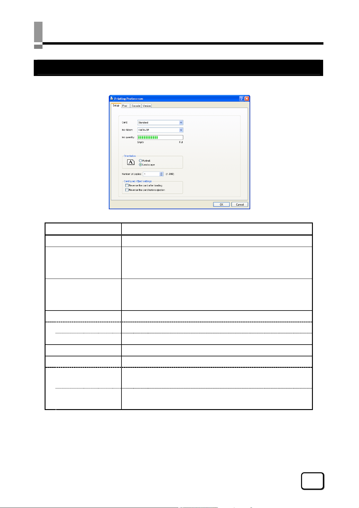
[ Setup ] Tab Sheet
Item Description
Card Choose the card to use.
Ink ribbon Choose the ink ribbon to use.
Note: The ink ribbon set inside the printer will be automatically
selected if communication with the printer is possible.
Ink quantity Indicates the remaining quantity of the ink ribbon.
Note: This is not displayed when communication with the printer is
not established.
Orientation Settings for printing orientation.
Portrait Vertical (Print with the shorter edge of the card on top.)
Landscape Horizontal (Print with the longer edge of the card on top.)
Number of copies The number of copies to issue. Enter a number up to 999.
Card Load / Eject Settings Settings for turns over the card.
Reverse the card
after loading
Reverse (turns over) the card after loading.
Reverse the card
before ejection
Reverse (turns over) the card before ejection.
3
Page 4
Printer Driver Settings (Cont’d)
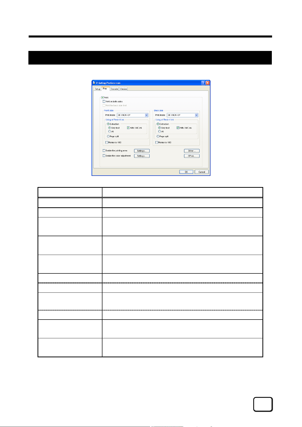
[ Print ] Tab Sheet
Item Description
Print Executes printing.
Print on both sides Prints both sides of the card.
Print the back side first
Front side Print settings for the front side of the card.
Back side Print settings for the back side of the card.
Enable the printing area Enable the function of the printing area.
Settings... Set the “non-printing area” in the specific ink. (Refer to page 6)
Enable the color
adjustment
Settings... Set the color adjustment. (Refer to page 7)
Dither For specifying settings related to dithering for the Resin K ink.
Prints the image on the back side first when printing on both sides of
the card.
(Refer to the next page.)
(Refer to the next page.)
Enable the function of the color adjustment.
(Refer to page 8)
OP ink For specifying settings related to OP ink print data.
(Refer to page 9)
4
Page 5
Printer Driver Settings (Cont’d)
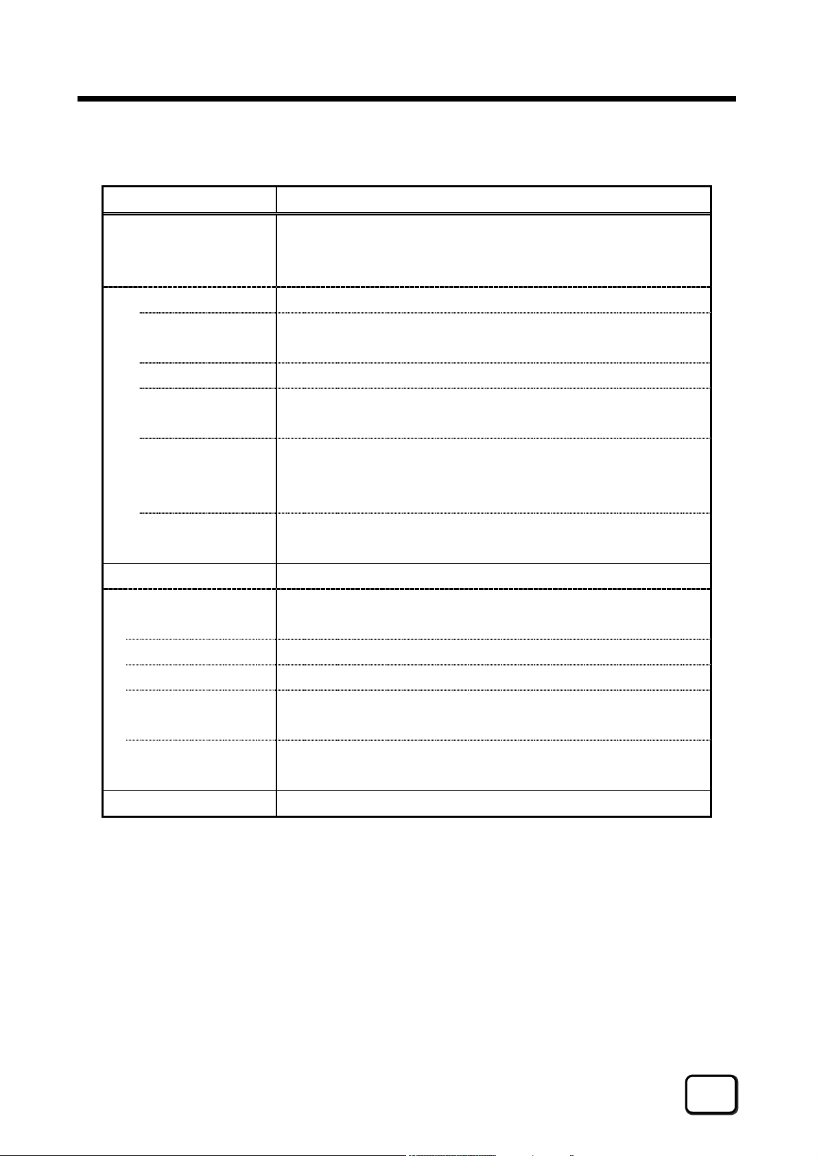
The following items are same function between “Front side” and “Back side”.
Item Description
Print mode Ink list. Specify the ink to use for printing.
Caution: Print error occurs if an ink that is not mounted to the printer
is selected.
01 YMC Prints using the YMC ink.
02 K Prints using the Resin K ink.
Prints the black color by the dither processing of the color image.
03 YMCK Prints using the YMC ink and Resin K ink.
04 YMC+OP Prints using the YMC ink.
Prints the setting data in the [OP ink] dialog using the OP ink.
05 K+OP Prints using the Resin K ink.
Prints the black color by the dither processing of the color image.
Prints the setting data in the [OP ink] dialog using the OP ink.
06 YMCK+OP Prints using the YMC ink and Resin K ink.
Prints the setting data in the [OP ink] dialog using the OP ink.
Using of Resin K ink For specifying the component to print using the Resin K ink.
Extraction Prints the black color component on each page using the Resin K
ink.
Only text Prints only the black color text using the Resin K ink.
All Prints all black color components using the Resin K ink.
With YMC ink Prints the background of the specified black color component
using the YMC ink.
Page split Prints the first page (odd pages) using the YMC ink.
Prints the second page (even pages) using the Resin K ink.
Rotate by 180 Prints the page upside down.
5
Page 6
Printer Driver Settings (Cont’d)
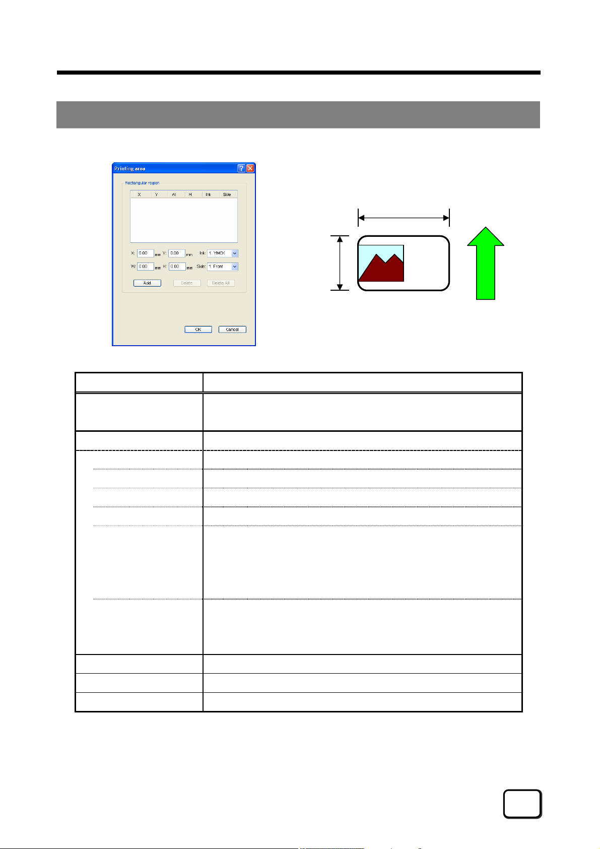
[ Printing area ] Dialog
X=0
Y=0
H
Y=53.5
Item Description
Rectangular region Area not to be printed within a registered rectangular region.
This rectangular region is called as “non-printing area”.
“non-printing area” information.
X Start X-coordinate of area by millimeter.
Y Start Y-coordinate of area by millimeter.
W
X=85.1
Direction of card loading
(Front side)
W Width of area by millimeter.
H Height of area by millimeter.
Ink Ink valid for the “non-printing area”.
1. YMCK : Area not to be printed using all YMCK inks.
2. OP : Area not to be printed using the OP ink.
3. ALL : Area not to be printed using all YMCKOP inks.
Side The side of the card for which the printing area is valid.
1. Front : Front side
2. Back : Back side
Add Registers the input data. You can enter up to 8 input data.
Delete Deletes the information selected in the list.
Delete All Deletes all registered information.
6
Page 7
Printer Driver Settings (Cont’d)
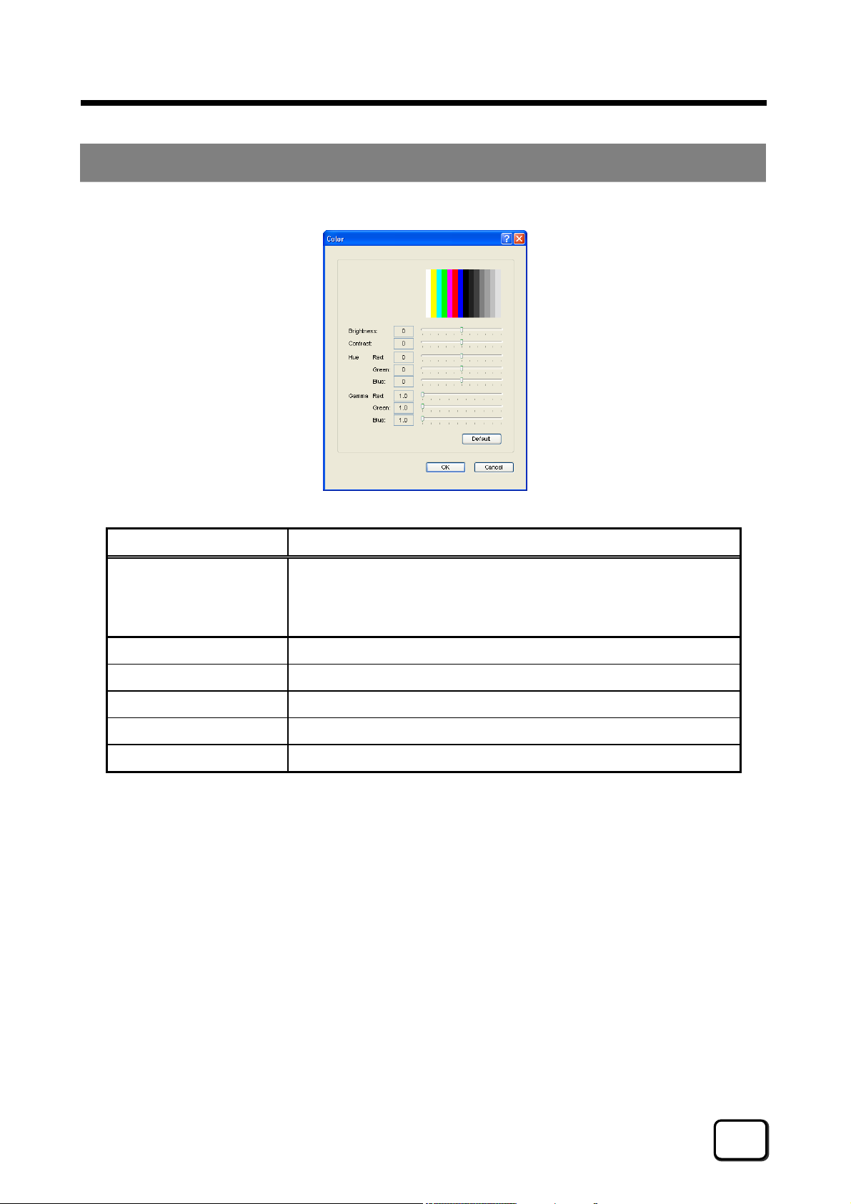
[ Color ] Dialog
Item Description
Settings related to color adjustment.
If the following slide bars are moved, the setting will be reflected in
the color area of this screen.
Brightness Brightness level.
Contrast Contrast level.
Hue Hue level.
Gamma Gamma level.
Default Restores the settings to the default values.
7
Page 8
Printer Driver Settings (Cont’d)
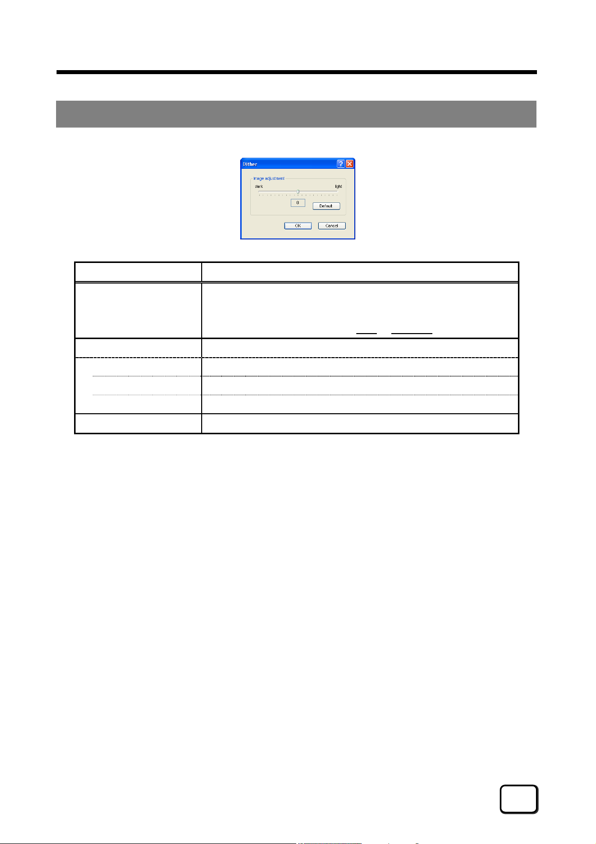
[ Dither ] Dialog
Item Description
Settings related to dithering.
Caution: This setting is valid only when the [Print mode] item inside
the [Print] tab is specified as
Image adjustment Image adjustment value.
dark Darkens the printed image after dithering.
(0) Default value.
light Brightens the printed image after dithering.
Default Restores the settings to the default values.
02 K or 05 K+OP.
8
Page 9
Printer Driver Settings (Cont’d)
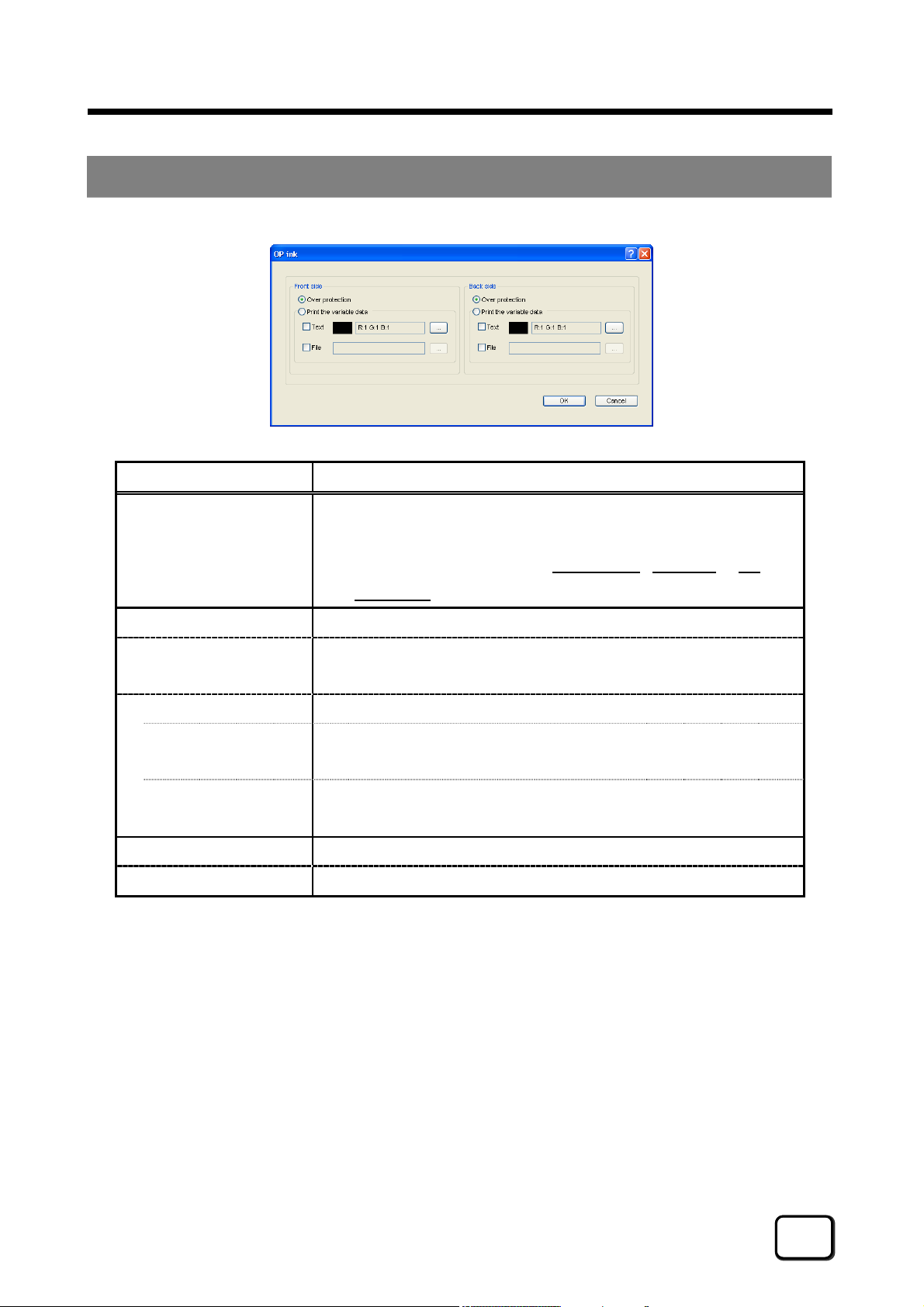
[ OP ink ] Dialog
Item Description
Front side Settings for the front side of the card.
Over protection Entire surface of a card is printed using the OP ink, and the printed
Extraction Prints a specific color component on each page using the OP ink.
Text Prints the text of a specified color using the OP ink.
File Prints a specified file using the OP ink.
Back side Settings for the back side of the card.
(Refer to settings for the front side.)
Settings related to the data to be printed using the OP ink.
Caution: This setting is valid only when the [Print Mode] item inside
the [Print] tab is specified as
YMCK+OP.
surface is protected.
Caution: White and black colors cannot be selected.
Caution: This file is 1006x633-pixel 24-bit BMP format.
04 YMC+OP , 05 K+OP or 06
9
Page 10

Printer Driver Settings (Cont’d)
[ Encode ] Tab Sheet
Item Description
Encode
IC Non-contact Allows writing of data to the non-contact IC.
IC Contact Allows writing of data to the contact IC.
Reverse the card
After IC encoding
Magnetic Allows writing of data to the magnetic stripe.
Reverse the card
After MG encoding
Settings for encoding.
Note: Only the unit installed within the printer is displayed as
enabled when communication with the printer is established.
Reverse (turns over) the card after writing data to the non-
contact/contact IC.
Reverse (turns over) the card after writing data to the magnetic
stripe.
10
Page 11

Printer Driver Settings (Cont’d)
[ Version ] Tab Sheet
Item Description
Version information. DCP360i Card Printer …
DCP360i Card Printer Driver [nnnn-xxxx-yy-zz]
nnnn : Version of printer driver.
xxxx : Version of firmware.
yy : Version of Config.
zz : Version of Table.
Note: Version information for the firmware, Config and Table will
appear as ‘0’ when communication with the printer is not
established.
Copyright ... Copyright information.
11
Page 12

Port Monitor Settings
[ Property ] Tab Sheet
Item Description
Port Name Name of the port. You can enter a name of up to 24 characters.
Unit Number List of connected printers. The selected printer is used for printing
the card.
Specify the unit number of the printer in use.
Caution: The setting is incorrect if the following message appears.
Displayed
Message
No Device Printer is not found.
No Selection Last used printer is not found. A different
printer is currently connected.
Description
[ Version ] Tab Sheet
Item Description
DCP360i Card Printer … Version and copyright information.
12
Page 13

Port Monitor Settings (Cont’d)
Error Code List
Below is a list of error codes for the printer unit. For details, refer to the printer unit’s instruction manual.
No. Error Code Description
0x01020401
1
0x01020480
2
0x01020481
3
0x01023A00
4
0x0102****
5
0x01030C00
6
0x01031100
0x01033600
7
Printer is initialization in progress.
Printer door is open.
Cleaning unit is not mounted.
No card in the cassette.
Printer is not ready.
Writing of magnetic encoding data failed.
Ink ribbon is not mounted or cannot be recognized.
0x01033B81
8
9
10
11
12
13
14
15
16
17
0x01033B**
0x0103****
0x01043681
0x0104****
0x01052080
0x01052081
0x01052401
0x01052680
0x0105****
Card jam occurred during card feed.
Card jam occurred during card feed or card transfer.
Media error is detected.
Ink ribbon is not mounted or faulty.
Hardware error is detected.
IC encoder is not installed.
Magnetic encoder is not installed.
Invalid selection of an ink ribbon.
Invalid magnetic encoding data.
Command error is detected.
0x010B****
18
19
0x01420081
0x01420082
Remaining ink ribbon level is 0.
Remaining laminating film level is 0.
13
Page 14

Port Monitor Settings (Cont’d)
Below is a list of error codes related to the printer driver.
No. Error Code Description
0x02******
1
0x09******
2
0x10000103
3
0x10000201
4
0x10000202
5
0x10000203
6
0x10000301
7
0x10000302
8
0x10000303
9
0x10001001
10
0x10001002
11
Printer is not found.
Command error is detected.
Writing of magnetic encoding data failed.
Contact IC encoding program is not found.
Unable to establish communication with contact IC encoder.
Writing of contact IC encoding data failed.
Non-contact IC encoding program is not found.
Unable to establish communication with non-contact IC encoder.
Writing of non-contact IC encoding data failed.
Ink ribbon cannot be recognized.
Invalid selection of an ink ribbon.
0x10001003
12
0x10001004
13
0x10002000
14
0x1000200*
15
IC encoder is not installed.
Magnetic encoder is not installed.
Printer is not found.
Printer is not ready.
14
Page 15

In-Line Encoding
In-Line Encoding Format
In-line encoding is possible when all the settings in the [Encode] tab are enabled.
Encoding data can be sent to the card printer through the printer driver using the special character strings
(prefixes) described below. This function is called as “in-line encoding”.
Adding a prefix (tilde (~), ?, or numeric characters) at the beginning of a text string enables the string to be
recognized as encoding data. Character strings including prefixes are not printed on the card when they
are recognized as encoding data.
No.
1
2
3
4
5
6
Remarks
[*1] Make sure that the string is not broken and uses the same font.
[*2] Encoding cannot be performed correctly if characters that are not consistent with the usable
[*3] The maximum string length is the number of characters including control codes and excluding
Prefix
character string
~?0
~?1
~?2
~?3
~?4
~?5
code table are used.
prefixes.
Text string following prefix [*1]
String becomes JIS2 magnetic encoding data. 7 units code 69
String becomes ISO track 1 magnetic
encoding data.
String becomes ISO track 2 magnetic
encoding data.
String becomes ISO track 3 magnetic
encoding data.
Reserved.
Reserved.
Usable character
code table [*2]
6 units code 76
4 units code 37
4 units code 104
Max. string
length [*3]
[**] Character strings that are processed as graphics, such as screen captures, may not be recognized
as encoding data. Processing of character strings is dependent on the application software.
[***] Enter the in-line encoding character string at the first screen of each card to be printed.
Example
Textbox character strings of
application software
ABC
~?1DEF
Character string to
be printed on card
ABC DEF
Encoding data to be sent
to ISO track 1
15
Page 16

In-Line Encoding (Cont’d)
Character Code Table
Below is the list of usable ASCII codes. Configure the character string to encode using the usable half-size
characters for each of the level codes.
ASCII character code table
b7 0 0 0 0 1 1 1 1
b6 0 0 1 1 0 0 1 1
b5 0 1 0 1 0 1 0 1
b4 b3 b2 b1 0 1 2 3 4 5 6 7
0 0 0 0 0
0 0 0 1 1
0 0 1 0 2
0 0 1 1 3
0 1 0 0 4
0 1 0 1 5
0 1 1 0 6
0 1 1 1 7
1 0 0 0 8
1 0 0 1 9
1 0 1 0 A LF
1 0 1 1 B
1 1 0 0 C
0 @ P ` p
! 1 A Q a q
“ 2 B R b r
# 3 C S c s
$ 4 D T d t
% 5 E U e u
&6 F Vf v
‘ 7 G W g w
( 8 H X h x
) 9 I Y I y
* : J Z j z
+ ; K [ k {
, < L \ l |
The range of
4 units code.
The range of
6 units code.
The range of
7 units code
for a text string.
1 1 0 1 D
1 1 1 0 E
1 1 1 1 F
The start sentinel and end sentinel listed below cannot be used in the encoding data.
Start sentinel
(Hexadecimal value)
4 units code
6 units code
7 units code DEL (7F) DEL (7F)
;
%
- = M ] m }
. > N ^ n
/ ? O _ o
(Hexadecimal value)
(3B)
(25)
?
?
~
DEL
End sentinel
(3F)
(3F)
Tilde character
(Hex-decimal: 7E)
16
Page 17

Setting Examples
Examples of Printing
Printing on Single Side (Landscape)
Application software
1page
Landscape
Printer
Ejection
1page
Printing
Print
Print mode: 06 YMCK+OP
Extraction
Only text
With YMC ink
Loading
Graphics
Te xt
Color
Black
Graphics
Te xt
Front side
YMC ink
YMC ink + Resin K ink
Front side
Protective layer
(OP) is printed.
17
Page 18

Setting Examples (Cont’d)
Printing on Single Side (Portrait)
Application software
1page
Portrait
Printer
Ejection
Printing
Print
Print mode: 03 YMCK
Extraction
Only text
Loading
Graphics
Te xt
Color
Black
Graphics
Te xt
Front side
YMC ink
Resin K ink
Front side
No Protective
layer (OP).
18
Page 19

Setting Examples (Cont’d)
Printing on Both Sides (Standard)
Application software
1page
Landscape
Ejection
2page
Print mode: 06 YMCK+OP
Extraction
Only text
With YMC ink With YMC ink
Printer
1page
Printing
Print
Print on both sides
Print mode: 06 YMCK+OP
Extraction
Only text
Loading
Graphics
Te xt
2page
Color
Black
Back side
Graphics
Te xt
Front side
YMC ink
YMC ink + Resin K ink
Front side
Protective layer
(OP) is printed.
19
Page 20

Setting Examples (Cont’d)
Printing on Both Sides (for Laminator)
Application software
1page
Landscape
Ejection
1page
Printer
2page
Printing
Print
Print on both sides
Print the back side first
Print mode: 05 K+OPPrint mode: 01 YMC
Loading
1st Page
2nd Page
When page 2 and subsequent pages are colored, dithering is performed and printing is executed
using the Resin K ink.
2page
Graphics
Te xt
Graphics
Te xt
Color
Color
Black
Black
Front side
Back side
Back side
Graphics
Te xt
Graphics
Te xt
YMC ink
YMC ink
Resin K ink
Resin K ink
No Protective
layer (OP).
Protective layer
(OP) is printed.
Back side Front side
20
Page 21

Setting Examples (Cont’d)
Printing on Both Sides (Special Mode)
This special mode may be economical for the ink. This function is supported by printer driver of version 3 (or
later).
Ink ribbon: YMCK-OP
Print
Print on both sides
Landscape
1st Page
2nd Page
Reverse the card before ejection
Application software
1page
2page
Graphics
Te xt
Graphics
Te xt
Color
Front side
Color
Black
Back side
Black
Ejection
1page
OP is
printed
2page
Back side
Graphics
Te xt
Graphics
Te xt
Printer
1page
Front side
YMC ink
YMC ink
Resin K ink
Resin K ink
Print mode: 02 KPrint mode: 04 YMC+OP
Loading
Printing
Front side
Protective layer
(OP) is printed.
No Protective
layer (OP).
When page 2 and subsequent pages are colored, dithering is performed and printing is executed
using the Resin K ink.
21
Page 22

Setting Examples (Cont’d)
Printing on Single Sides (OP ink Graphics)
OP File
OP
OP1.bmp
Print
Print mode: 06 YMCK+OP
Extraction
Only text
With YMC ink
Print the variable data
File
Application software
Eject
Page 1
Page 1
OP
Front side
Graphics
Te xt
The OP file is converted into 2 gradation and printing is executed using the OP ink.
Colored
Black color
Graphics
Te xt
YMC ink
YMC ink + Resin K ink
OP ink OP1.bmp
Printer
Print
Load
Front side
22
Page 23

Setting Examples (Cont’d)
Page Split
Application software
1page
Landscape
Ejection
2page
1page
Printer
Printing
Print
Print mode: 06 YMCK+OP
Page split
Loading
1st Page
2nd Page
2page
Graphics
Te xt
Graphics
Te xt
Color
Color
Black
Black
Graphics
Te xt
YMC ink + Resin K ink
YMC ink + Resin K ink
Front side Front side
Protective layer
(OP) is printed.
23
Page 24

Setting Examples (Cont’d)
Examples of Encoding
Encoding without Printing
Print
IC Non-contact
IC Contact
Magnetic
Graphics
Te xt
Application software
~?5NIC
~?4IC
~?1ISO
Color
Black
inline Encoding
Printer
Ejection
Non-contact IC encoding
Contact IC encoding
Magnetic Encoding
Front side
Graphics
Te xt
Non-contact-type IC encoding data
Contact-type IC encoding data
Nothing
Nothing
Loading
Front side
No Protective
layer (OP).
NIC
IC
“ISO track 1” magnetic encoding data
ISO
24
Page 25

Setting Examples (Cont’d)
Encoding with Printing
Enable the printing area
Print
Print mode: 06 YMCK+OP
Extraction
Only text
With YMC ink
IC Non-contact
IC Contact
Magnetic
Reverse ...
Graphics
Te xt
Application software
~?5NIC
~?4IC
~?1ISO
Color
Black
inline Encoding
Printer
Ejection
Front side
Graphics
Te xt
Non-contact-type IC encoding data
Contact-type IC encoding data
“ISO track 1” magnetic encoding data
YMC ink
YMC ink + Resin K ink
Non-contact IC encoding
Contact IC encoding
Magnetic Encoding
Reverse the card
Printing
Loading
Back side
Protective layer
(OP) is printed.
NIC
IC
ISO
25
Page 26

Setting Examples (Cont’d)
Encoding with Printing (JIS magnetic stripe card)
Print
Print mode: 06 YMCK+OP
Only text
With YMC ink
IC Non-contact
IC Contact
Magnetic Extraction
Reverse ...
Graphics
Te xt
Application software
~?5NIC
~?4IC
~?0JIS
Color
Black
inline Encoding
Printer
Ejection
Front side
Graphics
Te xt
Non-contact-type IC encoding data
Contact-type IC encoding data
“JIS type 2” magnetic encoding data
YMC ink
YMC ink + Resin K ink
Non-contact IC encoding
Contact IC encoding
Magnetic Encoding
Reverse the card
Printing
Loading
Back side
Protective layer
(OP) is printed.
NIC
IC
JIS
26
Page 27

Setting Examples (Cont’d)
Diagram of Reversing Card
Ejection
Side A
Reverse the card after loading
Reverse the card before ejection
Printing Loading
1page
Side A
Side B
1page
Side B
2page
Magnetic
Encoding
Side B
Printing on both sides
Reverse the card after IC encoding
Reverse the card after MG encoding
Contact IC
Encoding
Side A
Non-contact IC
Encoding
Side A
Side B
Logical configuration of the printer
27
Page 28

FAQ (Frequently Asked Questions)
Q
Ink ribbon settings are automatically restored to their default settings upon changing.
A
Ink ribbon set inside the printer is automatically selected.
[Important] When the printer is connected locally, there is no need to perform ink ribbon setting.
Q
Remaining ink ribbon level is not displayed.
A
The printer may not be properly connected. Check the connection and power supply of the printer.
[Note] When the printer is connected to the shared network, information on remaining ink ribbon level
cannot be acquired from a client PC.
Q
The card is discharged without being printed.
A
The [Print] check box of the [Print] tab is not ticked. Tick the [Print] check box. (Refer to page 4.)
Q
How can I print black color using the Resin K ink ?
A
Choose the [Mode] item of [Printing] tab except "01 YMC" and "04 YMC+OP". (Refer to Page 5)
Q
How can I perform magnetic/IC encoding ?
A
Exclusive applications are required for methods other than in-line encoding. Please consult our
authorized dealers for details.
Q
How can I print using the OP ink on partial areas instead of the entire surface of a card ?
A
Set the area for which OP ink is not to be printed in the [Printing area] dialog. (Refer to page 6.)
Q
How can I print OP graphics using the OP ink ?
A
Set the OP function using the [OP ink] dialog. (Refer to 9 or 23 pages)
Q
Values for firmware, Config and Table versions are displayed as ‘0’.
A
The printer may not be properly connected. Check the connection and power supply of the printer.
[Note] When the printer is connected to the shared network, version information cannot be acquired
from a client PC.
Q
I cannot print a card using a network-shared printer which connected via USB.
A
When the access authority of the computer is not proper, the printer may be unable to print, even if
installation of the printer driver is completed by the shared network. Please make the access authority
properly according to the instructions of the
network administrator.
28
Page 29

Direct Dye Sublimation Printer DCP360i Printer Driver Instruction Manual
Copyright 2007 Victor Company of Japan, Limited
KAT-T199-107
 Loading...