

Digital Guard Dawg 2GO KEYLESS iKEY RS Installation & User Manual


Package Contents ………................................................. 4
Pre-Installation Information and Preparation ..................5
Major Component information….....................................6
Part #1
Door Lock & Alarm Module (Harness Connections).......9
Door Locking System Wiring............................................ 11
Door “Open” Triggers.................................................... 13
Antenna Installation ………...............................................15
Function Jumper Set & External Siren Diagram...........16
Door Lock Wiring Diagram Appendix “A” & “B”…………….……… 25
PKE Module Wiring Diagram …………….……….... 27
PKE Passive Keyless Door Lock & Alarm…............8
Part #2 PBS Push Button & Remote Start...................17
Different Types of Push Button Start Installations...........18
Push Button Start Module (Harness Connections).....20
Start Button Dimensions.........................................24
Push Button Start Wiring Diagram ………….……… 28
Push Button Start High Current Wiring Diagram….……… 29
Basic System Operation.........................................30
2

IMPORTANT
1) This product must be installed by a qualified professional
according to these instructions and observing all safety features.
2) The Digital Guard Dawg Inc. accepts no responsibility for any
electrical damage resulting from improper installation of the
product, be that either damage to the vehicle itself or to the
product.
3) Before starting ensure the vehicle to be installed has proper
grounding and no electrical shorts.
4) Completely read the Product Installation Guide carefully before
beginning any work.
FCC NOTICE
This device complies with part 15 of the FCC Rules. Operation is subject to the
following two conditions: 1. This device may not cause harmful interference,
and 2. This device must accept any interference received, including interference
that may cause undesired operation. FCC WARNING This equipment has been
tested and found to comply with the limits for a Class B digital device, pursuant
to Part 15 of the FCC Rules. These limits are designed to provide reasonable
protection against harmful interference in a residential installation. This
equipment generates uses and can radiate radio frequency energy and, if not
installed and used in accordance with the instructions, may cause harmful
interference to radio communications. The manufacturer is not responsible for
any radio or TV interference caused by unauthorized modification to this
equipment. Such modifications could void the user’s authority to operate the
equipment.
3

The 2GO KEYLESS™ PKE- & PBS systems come in individual boxes. The
following is a list of components included with each kit:
PKE Door Lock & Alarm Kit:
1 – Door Lock & Alarm Control Unit
1 – RFID iKey™
1 – RFID Emergency Card
1 – Door Lock & Alarm Ma in Harness
1 – Door Lock & Alarm Accessory Harness
2 – Front Main Antennas
1- Antenna “Y” adaptor
1 – Emergency Backup Antenna
1 – Dual Color Dash Mounted LED Indicator
- 7 PIN
- 7 PIN
Push Button Start Kit:
1 – Push Button Start Control Unit
1 – Push Start Button
1 – Push Button Main Harness
1 – Push Button Accessory Harness
1 –Installation Guide / User Manual
- 8 PIN
- 10 PIN
4

Overview:
Completely read this manual and review the wiring diagram carefully.
It is recommended that you complete your installation in two parts.
Part 1~Installation of the Door Lock and Alarm module & Harnesses.
Part 2~Installation of the Push Button–Remote Start & Harnesses.
1. Always install in a well-lit, dry, covered area away from the elements and keep
at least one window open during installation to avoid a lock out.
2. Locate necessary wires related to the installation (most required wires are
under driver dash or kick panel areas). Use only a digital multi-meter to verify
signal wires. Please be aware of surrounding metal and prevent accidental
grounding of wires through various tools being used during the installation
process.
3. Disconnect the ground wire (-) terminal from the vehicle’s battery prior to
making ANY connections. To avoid accidents, it is recommended to remove
related fuses from sockets before making connections and put them back
during the very last steps.
4. Mount the Control Module in a secure area, away from vehicle computers and
heating/air conditioning ducts. The location should be convenient for your
installation, but well hidden from thieves. Try to mount the unit as far away from
metal objects to increase the range of the iKey™ Transmitter.
5

5. Route the wires of the harnesses along factory wiring to areas in which the
different connections will be made. DO NOT plug the two wiring harnesses into
the Control Module until all connections have been completed. When running
the harness wires through the vehicle, be careful to run them where they could
be damaged or shorted to GROUND. Keep them away from ALL MOVING
PARTS of the vehicle or where high heat could damage their insulation. Always
protect the harness wires where they pass through holes in metal panels by
using rubber grommets. Secure wires to factory harnesses using zip ties and
use wire loom where appropriate.
6. Once the control unit is connected, begin function tests only after verifying and
ensuring all wires have been connected and insulated properly. Do not power
up the module before it is properly grounded. If the unit is powered before
being grounded, serious damage to internal components could occur.
Immobilizer and Data Interfaces
Many vehicles on the road manufactured after 1995 utilize some form of factory
security that requires a code that is passed between the key and the vehicle.
Different manufacturers use different methods to incorporate this into the ignition
cylinder of which RF or a key (or cylinder) impregnated resistor is the most popular.
These types of security are in place to disable the “cranking” of the motor and are
known as Immobilizers.
Data Interfaces have become popular with aftermarket products as obd2 and
CANbus interfaces have evolved over the last 15 years. Aftermarket Data
Interfaces utilize analog wire signals from 2GO-Keyless™ system and translate
them into data that the vehicle can use to lock / unlock doors, monitor door open /
closed status, etc. In many cases Data Interfaces and Immobilizers are combined
into one unit and are manufactured by various aftermarket companies.
In vehicles manufactured after 1995 an Immobilizer or Data Interfaces module
may be necessary for the installation of Keyless Entry and Push Button Start of the
vehicle while maintaining all factory features. This manual will serve only as a
general guide to the installation of the 2GO-Keyless™ system, consideration of
Immobilizer or Data Interfaces devices and their installation should be done by a
professional.
If you need assistance locating an Immobilizer or Data Interfaces device for your
vehicle contact us at (877) 2GO-KEYLESS or 877- 246- 5395
6

Control Module and Push Button Start Module: Select a mounting location
behind the dash, and secure using cable ties. Be certain that the chosen location
will not interfere with the proper operation of the vehicle. Avoid mounting the
module to or routing the wiring around the steering column, as the module or wiring
could wrap around or block the steering wheel preventing proper control of the
vehicle. Do not mount the modules in the engine compartment, as it is not
waterproof.
Start Button:
STOP modes of your vehicle’s ignition system. In addition, the Start Buttons LED
provides a visual indication of when the system has recognized a valid RFID iKey™
and when the vehicle is ready to be started. Typically the Start Button is installed in
the dash or center console of the vehicle, but it can be installed in any location
within the length of the buttons 32” harness. Your choice of Start buttons will
determine the diameter and depth of hole needed for button installation. Be sure
and confirm that your have ample room behind the dash for the type Start Button
you have choose. Specific Start Button dimensions can be found on page 24 of this
manual.
Dash Mounted LED:
is a secondary visual indicator of the system mode. This LED is not required to be
used, but if installed will indicate when the systems alarm features Arm and Disarm,
as well as provide a “Flashing” warning to notify wood be thieves that your vehicle is
protected. If installing this LED, locate it where it can be easily seen from outside
the vehicle, yet not be distracting to the driver. Once a location has been selected,
check behind the panel for wire routing access, and confirm the drill will not damage
any existing components as it passes through the panel. Drill a 19/64” (7.6mm)
hole, and pass the wires from the LED through the hole, from the front of the panel.
Firmly press the body of LED into the hole until fully seated.
(Optional) Siren:
vehicle’s OEM horn, you will need to open the control module case and change the
systems jumper set (JP4) according the wiring diagram. * for more information see
“Jumper Sets” page 16. Always mount the Siren away from heat sources such as
radiators, exhaust manifolds and turbochargers. Mount it in an area where it will not
be in the way for mechanics and so that it cannot be easily reached from below the
vehicle. Mount it so that its sirens opening points down to prevent it from collecting
water.
The system Start Button is used to control your Start, ON, ACC &
A dual color (Red / Blue) LED is also included in this kit. It
If you are installing a Siren instead of connecting to the
7

The Door Lock and Alarm Module will provide completely automatic operation of all
vehicle doors and all security functions.
As you approach your vehicle doors will unlock upon seeing a valid iKey™
Walk away from the vehicle, all doors auto lock and security features arm
PKE Module iKey™
.
Installation should begin with selecting a location to mount the system module
and locating of all signal wires listed below. Once a location has been selected,
mount the Door Lock / Alarm module and connect wires according the systems
wire diagram.
8
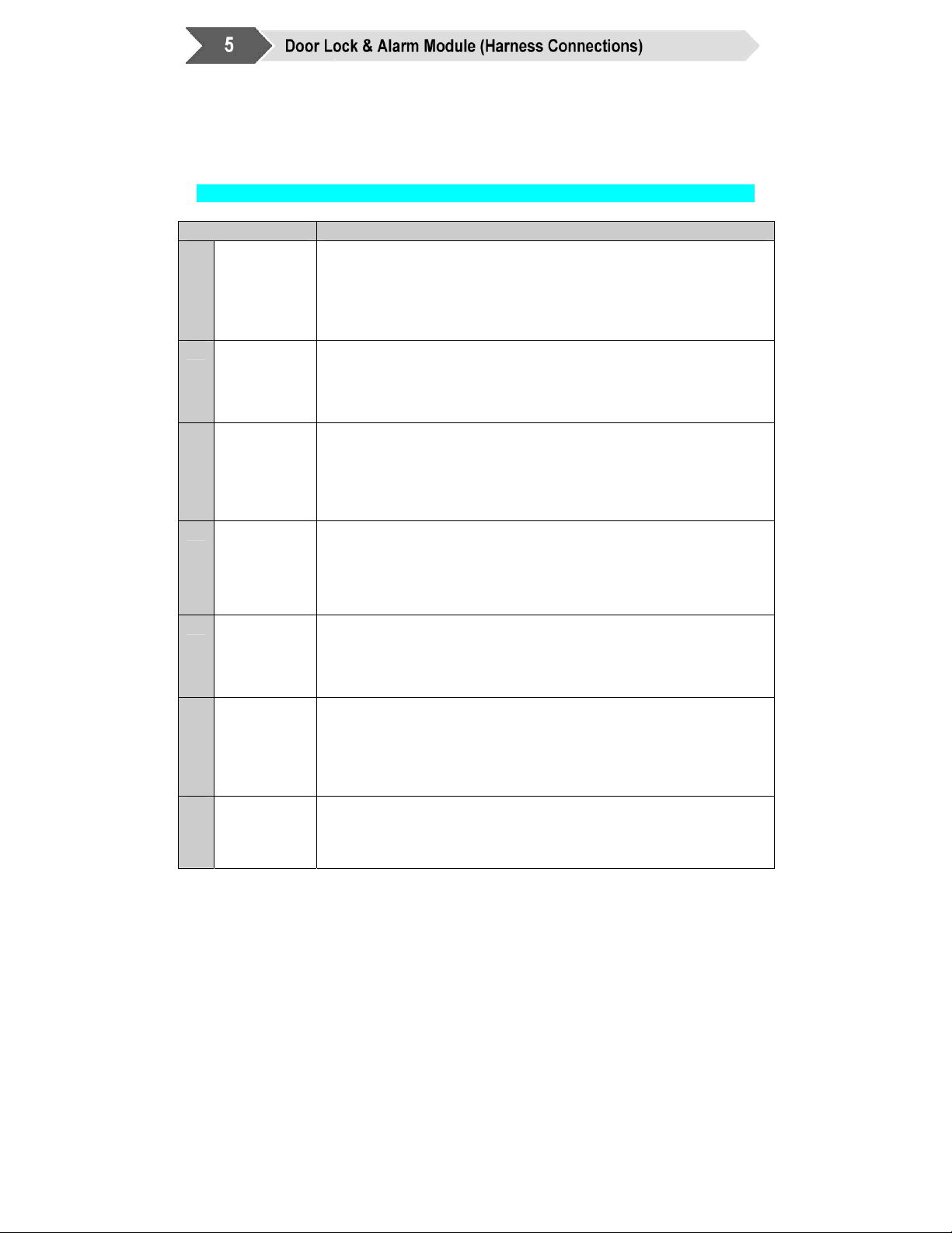
Connect the Ground wire first befor e making th e 12-volt connections to the
Module. Powering up before grounding could damage the system!
PKE Door Lock & Alarm ~ Main Harness (7-Pin)
Use wire color for identification, Actual wire order in harness m ay be different.
Wire Description
1
2
3
4
5
6
7
Black
Red ( + )
12V
Battery
Chassis
Ground
( - )
Gray
(2 Wires)
Parking
Light
Purple
(-) OE Horn
or Siren
Blue
(-) Unlock
Green
(-) Lock
Brown
Trunk
Release (-)
Connect to the 12V supply wire of the Ignition harness. Ensure that the
OEM power wire is fuse is more than 15A.
Note: certain new vehicles have no suitable 12 volt source at the
IGNITION switch (the 12 Volt wire is too small to supply the
necessary current). In this case, the fuse box, or the B+
connection on the battery is recommended.
This wire is the system Ground and must be connected to bare,
unpainted metal Chassis or true Body ground. It is preferable to use a
factory ground bolt rather than a self-tapping screw. Screws tend to
get loose or rusted over time and can cause erratic problems.
This wire is provided to flash the vehicle’s parking lights. Connect one
gray wire to the output side of one of the vehicle’s parking lights. Or
use both gray wires to connect to the L & R turn indicator wires. If only
one wire is required, remove fuse and terminate second gray wire
appropriately.
Connect to the vehicle’s OEM horn or to an external Siren. Connect
directly to NEGITIVE side of vehicle’s horn control wire or connect to a
siren using the diagram on page 16 of this manual. The control wire will
usual be under the steering wheel and should be negative when honk.
If you have a negative-trigger central locking system, directly connect
this wire to the door UNLOCK signal wire.
Please refer to page 11 for more information on other central locking
system trigger types. If a Data Interface is used, connect to
modules “Door Output Status wire”.
If you have a negative-trigger central locking system, directly connect
this wire to the door LOCK signal wire.
Please refer to page 11 for more information on other central locking
system trigger types. If a Data Interface is used, connect to
modules “LOCK” input wire.
500mA negative output This output is used to control Trunk release
(1-sec. pulse) and operates only when Ignition is OFF.
9

Door Lock & Alarm
Wire Description
1
Vehicle ON Detect
2
Door Trigger
Red
(+)
Green
Default
(-) Negative
~ Accessory Harness (7-Pin)
This wire is for sensing when the vehicle is ON. It should be
connected to an Ignition wire that has +12 V when the Ignition
Key or Push Button Start is in the and ON (RUN) position.
Special instructions when using Remote Starter: Connect to
different ACC wire if the vehicle has 2nd ACC.
This wire senses when a vehicle “door open status”. If you
have a negative-trigger door switch system, you can directly
connect this wire to the door switch signal wire.
If you have a positive–trigger or are not sure, refer to page 13 for
more information on door switch system trigger types. Note:
Default function setting is Negative door switch. Change PKE
modules jumper (JP1) to Positive when vehicles use positiveswitch Dome Light circuit.
If a Data Interface is used, connect to modules “UNLOCK” input
wire.
3
4
Brown
(+) Brake
5
Purple
6
OE Alarm
Factory Disarm
output (-)
7
EMPTY
Blue
White
Connects to Window Rollup Module “Optional”
This wire senses when you step on the Bra ke. The wire will be
+12V as you depress the brake pedal, and will be ground when
release brake.
This wire provides the data control signal for the 2GO-Keyless™
Push Button – Remote Start Module. Connect this wire to the
(Purple) input signal wire of the Push Button Start module.
If needed, this wire can provides a Ground when Armed or
Disarmed signal that can be used as a “Factory Disarm W i re” for
a OEM Alarm system
10

All power door locking systems utilize switches or a central computer called the
Body Control Module (BCM) to control the locking and unlocking of the vehicle.
The switch is usually located on the door or center console while the BCM is
usually located under the Dash. Most locking systems will have at least 2
control wires, one for locking your doors called the LOCK wire, and one for
unlocking your doors called the UNLOCK wire.
You can refer to your vehicle’s electrical service manual for details on location
and color coding of Locking/Unlocking wires or you can find them by tracing the
wires from the door switches. Remember to only use a Digital Multi Meter when
testing for vehicle wires.
When testing a wire to "lock", your LOCK wire establishes a
connection to either a negative or a positive source, this will be the
signal to your vehicle to trigger a locking signal to the door lock
actuator or BCM to lock. Vice versa if you are testing for “unlock”.
Negative and Positive triggers are the two main types of door locking systems.
On a negative trigger system your LOCK and UNLOCK wire uses (-) negati ve
sources to signal the vehicle when you activate unlock or lock. In a positive
trigger system, your LOCK and UNLOCK wire uses (+) positive sources to
signal the vehicle when you activate unlock or lock.
Certain Manufactures such as Dodge/Chrysler utilize a single wire system
called a multiplexer. This single control wire uses one wire in combination with
resistor values to communicate to the BCM to LOCK and UNLOCK the vehicle.
Please refer to Appendix B Figure 2.
11
 Loading...