

User Manual
HDMI Matrix Total Digital Connectivity Solutions
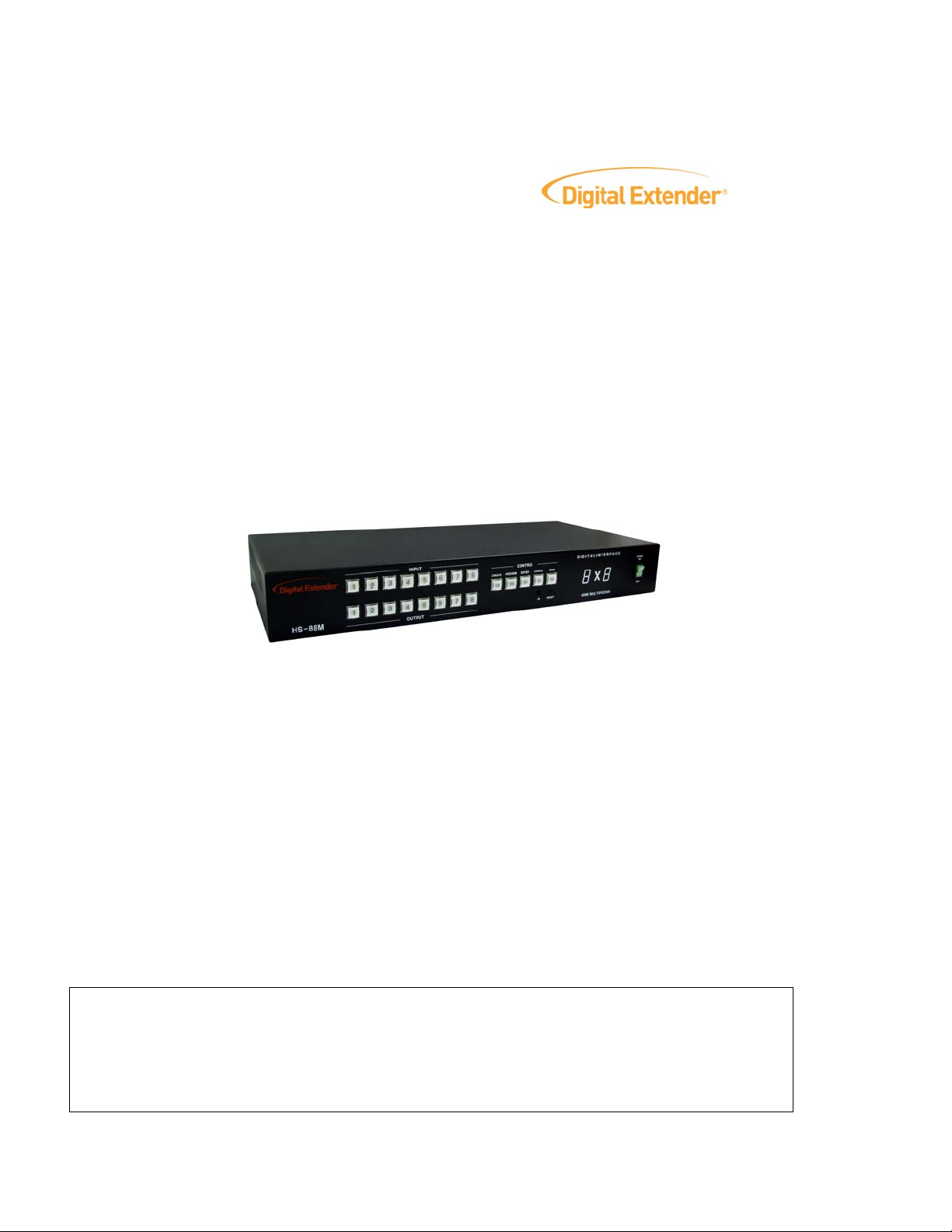
HS-66M/HS-88M
Cautions:
1. Digital Extender® logo is the trademark of RTcom USA.,Inc.
2. HDMI is the trademark of hdmi.org
3. Any product may be changed without any notice in order to improve the function of the product.
4. The design and specification of the product may be changed without any prior notice.
Copyright 2007 RTcom USA., Inc.
1

Table of Contents
1. BASIC UNDERSTANDINGS OF THE PRODUCT .............................................................................................................3
1-1 CAUTIONS FOR SAFETY.........................................................................................................................................................3
1-2 PACKAGE INCLUDES .............................................................................................................................................................4
1-3 FEATURES OF THE PRODUCT.................................................................................................................................................4
1-4 INSTALLATION ENVIRONMENTS AND METHODS....................................................................................................................4
1-5 NAMES AND FUNCTIONS OF EACH PART................................................................................................................................5
2. FUNCTIONS OF THE PRODUCT........................................................................................................................................6
2-1. SYSTEM OPERATION CONFIGURATION DIAGRAM..................................................................................................................6
2-2 SPECIFICATIONS OF THE PRODUCT.......................................................................................................................................7
3. HOW TO USE..........................................................................................................................................................................7
3-1 HOW TO SET CHANNELS ........................................................................................................................................................7
3-2 OPERATION BY FRONT BUTTON............................................................................................................................................8
3-3 PRODUCT ID SETTING...........................................................................................................................................................8
3-4 RS-232C (COM PORT) COMMUNICA TION SETTING ............................................................................................................9
4. COMMUNICATION CODE CONFIGURATION................................................................................................................9
4-1 CONFIGURATION OF RS-232C COMMUNICATION CODE........................................................................................................9
4-2 LAN (TCP/IP) COMMUNICATION SETTING.........................................................................................................................12
4-3 CONNECTOR PIN ASSIGNMENT...........................................................................................................................................15
5 WARRANTY INFORMATION .............................................................................................................................................16
5-1 ONE YEAR WARRANTY ........................................................................................................................................................16
5-2 WARRANTY LIMIT A TION AND EXCLUSION........................................................................................................................... 16
5-3 RETURNS ............................................................................................................................................................................16
Copyright 2007 RTcom USA., Inc.
2

1. Basic understandings of the product
1-1 Cautions for safety
• All the safety and user manual should be read before the appliance is operated.
• The safety and operating instructions should be retained for future reference.
Unplug this product from
• the wall outlet before cleaning. Do not use liquid cleaners or aerosol cleaners. Use a
damp cloth for cleaning.
• Do not use this equipment near wet place.
•
This product should be operated only from the type of power sources indicated on the marking label. If you are
not sure of the type of power supplied to your home, consult your local power company. For equipment
intended to operate from battery power, or other source, refer to the user manual.
This equipment may be equipped with a 3 wire grounding-type plug, a plug having a third (grounding) pin.
•
This pin will only fit in to a gr
plug in to the outlet, contact your electrician to replace your obsolete outlet. Do not defeat the safety purpose
of the grounding-type plug.
ounding type power outlet. This is a safety feature. If you are unable to insert the
• Openings on the case are provided for ventilation and to ensure reliable operation of the equipment and
protect it from overheating. The openings should never be blocked.
• Do not use any damaged power cords or plugs, or loosed outlets, this may cause electrical shock or fire.
Do not pu
• t heavy articles such as other equipments on this product.
• Keep it away from liquid, magnetic, inflammable substances.
• It is suggested to perform the product three minutes after the power is on for a precise measurement and
analysis.
to
Copyright 2007 RTcom USA., Inc.
3

P ckage Includes
1-2 a
• Main body: HS-66M/HS-88
M
• Power adapter: DC12V, 5A 60W
• RS232C cable/ LAN cable
• Rack Ears
• User’s manual
• IR Remote Controller
1-
3 Features of the product
Th D MI version 1.3 and full matrix routing functions it is
e H MI Matrix Router supports the highest quality of HD
possibl
ma
e to transmit high definition A/V signals from any of up to six or eight sources to any of 6 or 8 displays, while
intaining HDCP (High-bandwidth Digital Content Protection) compliance.
.
Compliant to HDMI v1.3, and DVI v1.0, the next genera
• tion standard for A/V connection
• Fully supports router function from one input to multi output routing
• Sup int at all outports HDCP Compla
• En r of digital signals
• Bu Identification Data (EDID) read function, with Electrically Erase Programmable
hanced quality and colo
ilt in Extended Display
Re (EEPROM), to save display EDID data while supporting any HDTV with maximum
ad-Only Memory
resolutions. The unit also supports user set up of non-Video Electronics Standards Association (VESA)
resolution, including projectors with unique resolu
put channels
tions.
• Supports HDTV Signal up to 1080p@60Hz with 36-bit color depth, Dolby® True HD, DTS-HD
• Control through 4 different method
- Front push button
- IR remote controller
- RS-232C COM port
- LAN (TCP/IP)
• It has an instantaneous noise protection circuit in input and output ports, therefore it can protect expensive
e
quipment from fault caused by noises (if any).
-4 Installation environments and methods
1
For installation, we recommend the following environments.
• Below 85 F (30°C) of ambient temperatur
Install and operate below 60% of ambient humidity (Best condition)
•
• Free of vibrations and dusts
• C input power (Recommended to use Uninterruptible Power Supply)
Stabilized A
Copyright 2007 RTcom USA., Inc.
with good ventilation condition
e (Best condition)
4
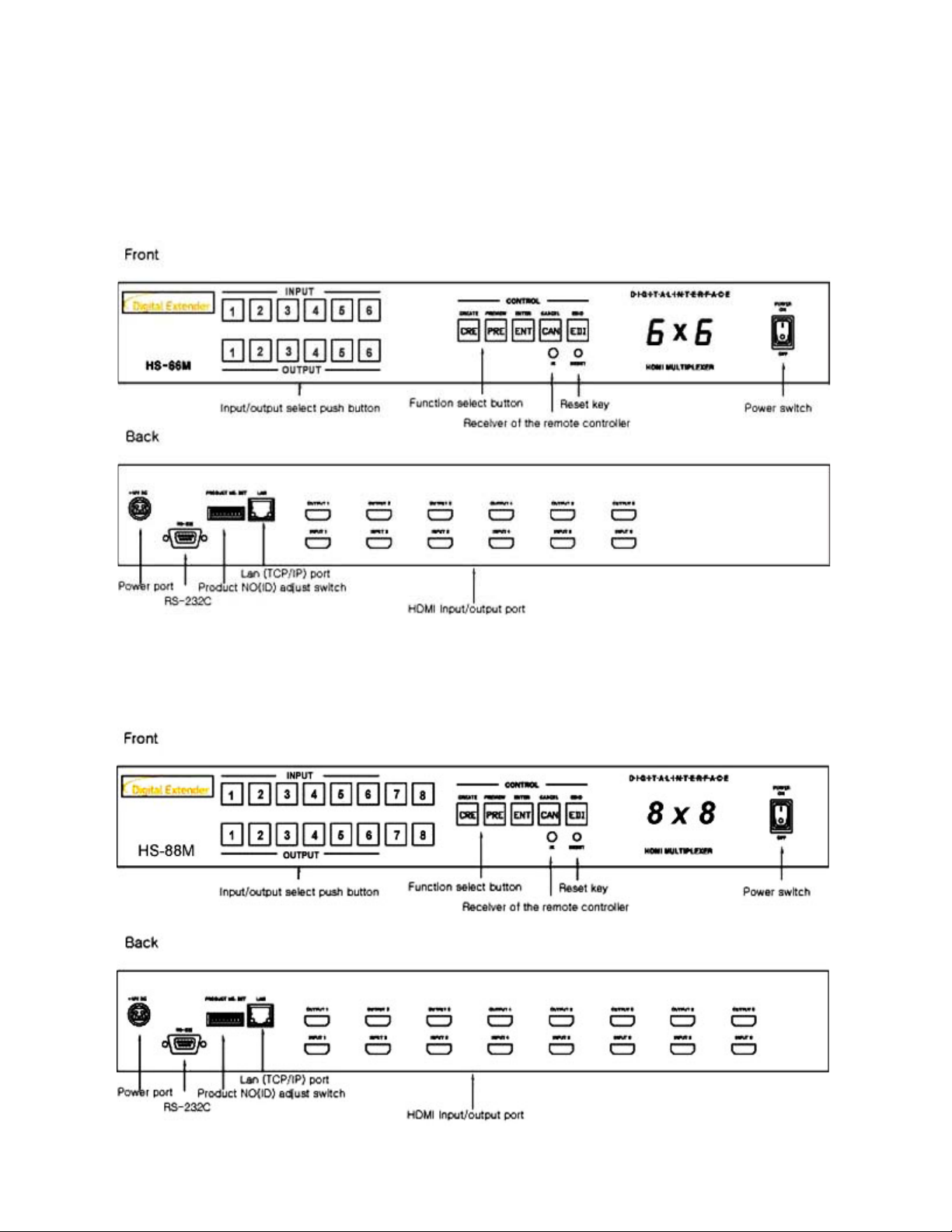
1-5 Names and functions of each part
< FRONT & BACK PANEL >
HS-66M
HS-88M
Copyright 2007 RTcom USA., Inc.
5

. Functions of the product
2
2-1. System operation configuration diagram
The configuration diagram of the matrix operation is shown in the following picture.
Any of the HDMI or DVI input signals can be transmitted to each output port by external RS-232C, LAN or fro
button.
nt panel
Copyright 2007 RTcom USA., Inc.
6

2-2 pe
S cifications of the product
• Type of signals: TMDS signals, digital R.G.B. & Audio
• Data transmission band: up to 2.25 GHz.
• 80i, 1080p@60Hz,1080i/720p@ Resolutions: 480p,720p,10
If customers display suppo
the EDID data should be saved to matrix first.
rts specific resolutions
such as VESA standard or projectors
120Hz, 2k,
• bCr, 4:4:4, 16/20/24/30/36-bit YCbCr, 4:2:2, 8/10/12/24/30/36-bit, RGB YC
•
Dolby® True HD, DTS-HD and DVD-Audio
• Router contr
• Input-output port: 6 inpu
ol: Front panel push button, IR remote controller,
RS-232C port: 9 pin female D connector,
LAN (T
CP/IP): RJ-45 Connector 10/100 Base-T
t / 6 output(HS-66M), 8 input / 8 output (HS-88M)
• Input-output connector: HDMI 19 pin female
• Power source: AC/DC Adapter 100-240 VAC / DC12V, 5A
• Power consume: 20 Watt
• Rack ear mountabl
• e (Wid * Length *Heigh 17.7 * 87 *2.3 * 2
Siz th t): 7. 6 inch (450 00 * 60 mm)
e 19” standard rack (2U)
• Weight: 6.77 lb (3.07kg)
3. t
How o use
3-1 How to set channels
If the switch is power ON, then preview
If each preview button is lit, then the initializ
1. Initialization display
----------- INPUT ----------------- ---------- CONTROL -----------
buttons are displayed with 2 steps as follow.
ation is completed.
12-bitYCbCr 4:2:2
1 2 3 4 5 6 CREATE PREVIEW E C EDID NTER ANCEL
CRE PRE ENT CAN EDI
1 2 3 4 5 6
----------- OUTPUT -----------------
2. Channel display and input selection
Aft he
er t initialization, preview button is lit.
-----------
1 CREATE PREVIEW ENTER CANCEL EDID 2 3 4 5 6
CRE PRE ENT CAN EDI
1 2 3 4 5 6
----------- OUTPUT -----------------
Copyright 2007 RTcom USA., Inc.
INPUT ----------------- ---------- CONTROL -----------
7

he functions of the switches are as follow.
T
Main power switch: matrix power on/off
•
• Remote controller receiver: receive infrared ray from remote controller
• Reset key: ini
• Input key: select cha
tialize the matrix
nnel from 1 to 6 or 8
• 6 or 8 Output key: select channel from 1 to
• Create (CRE) key: change input/output channel
• Preview (PRE) key: preview the status of current
• Enter (ENT) key: save current selection
• Cancel (C
AN) key: cancel current selection
connection
• h is connected to output EDID (EDI) key: read EDID data from display and then save data to matrix, whic
ports
3-2 Operation by Front Button
Input/output channel check:
Preview (PRE) button →
Input # button: present set channels are displayed in sequence
Input/output channel change
Create (CRE) button → Input # button set → Output ## button (Multiple selection) set
he connection of the channels are changed
t
* If you want to cancel, and then pre
Example: CH# 1 input to 1,2,3
Create -> Input 1 -> Output 1,2,3,4 -> Enter
ave (EDID) data
S
1, Disconnect the all input
2, Connect HDMI Matrix output to display directly (projector
, Power on both of HS-66M or HS-88M and Display (If you connect AV Receiver, disconnected display from the
3
Receiver)
(on r multiple) → Enter (ENT): Read EDID data of display and save them
If t ligh
, P wer
, ect all input cables
5 Conn
6,
Power on HDMI Matrix first.
7,
Power on all the Input sources and display (Power plug in and turn on set-top box)
#
- -#: Select only on channel
#: Sele
- All push b
- If you use DV first.
DID (EDI) button → Select one of output3, E
e o to matrix.
o off all devices 4
ct multiple channels
uttons are on / off toggle (Light ON - Selected)
I display, the EDID data should be saved to matrix
port cables on HDMI Matrix (The power set-top box should be unplugged (not sw. off)
ss cancel(CAN) button.
,4 output with same picture
, DVI monitor or AV Receiver),
# button (which is connected with display) → Input # button to be set
(ENT) he t of the buttons on then just enter
→ Enter (ENT) button:
IR Remote Control unit
Create - -># (ex: 1) -> OUT -># (ex: 1, 2, 3, 4) -> Enter
3-3 ro
>IN
P duct ID setting
•
Dip switch sets address for each matrix if many matrixes are used.
• Dip switch sets in binary value.
Copyright 2007 RTcom USA., Inc.
8
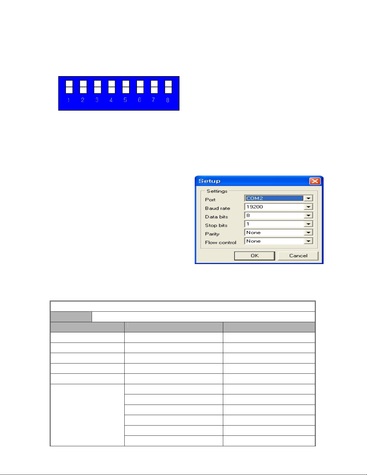
Ex)
Product ID = 01 (00000001b) -- 1 ON, 2 OFF, 3 OFF, 4 OFF, 5 OFF, 6 OFF, 7 OFF, 8 OFF,
Product ID = 10 (00001010b) -- 1 OFF, 2 ON, 3 OFF, 4 ON
Product ID = 23 (00010111b) -- 1 ON, 2 ON, 3 ON, 4 OFF
, 5 OFF, 6 OFF, 7 OFF, 8 OFF,
, 5 ON, 6 OFF, 7 OFF, 8 OFF
D0 D1 D2 D3 D4 D5 D6 D7
LSB MSB
• The product number is the value set in dip switches
255. The value “0” is not available.
**The product ID is set number “1” at the time of its delivery (Fa
of the equipment and can be set in the values of 1 ~
3-4 RS-232C (COM PORT) communication setting
After booting the matrix, connect RS-232C cable and
then ication settings as follows:
make commun
• e
Execute MiniT rm.exe or hyper terminal.
• Commu tting:
You may set port COM 1 ~ 4 or you may use all
availab
nication se
le ports.
4. Communication code configuration
4-1 Configuration of RS-232C communication code
From Co
mputer
ctory Default).
Code (46Byte) Start Header (3Byte) | Product ID (2 ) | Command (2Byte) | Data (38Byte) | yte) Byte Tail (1B
Code Name Byte Data Function
Start Header 2 ) R t 1h (! equest Frame Star
Start Header 30h (0) Request Frame Start
Start Header 31h (1) Request Frame Start
Product ID 30h ~ 39h (DIP Switch Set) Product Number
Product ID 30h ~ 39h (DIP Switch Set) Product Number
Command
Copyright 2007 RTcom USA., Inc.
01 Input SW Assign
02 Input SW Assign Salvo
03 ED n IE SW Assig
04 EDID SW A gn Salvo ssi
10 Assignment Status Request
20 Reset
9

Firmware Version Request 30
40 RS gn 232C Assi
Input Data10 30h ~ 39h I nput Channel Select
Input Data1 30h ~ 39h Input Channel Select
Ou 30h ~ 39h Ou a tput First Data10 tput A Input Select Dat
Ou a1 Outp ata tput First Dat 30h ~ 39h ut B Input Select D
Out 10 Outp ata put Last Data 30h ~ 39h ut N Input Select D
Output Data1 Outp ata Last 30h ~ 39h ut O Input Select D
Tail (End) 2Ah(*) Frame End
From Matrix
Code (4Byte) Head (1byte) | Address (1Byte) | PN (1Byte) | Tail (1Byte)
Code Name Byte Data Function
Head (Start) 21h Reply Frame Start
Start Head Request Frame er 30h (0) Start
Sta Head 31h (1) R uestrt er eq Frame Start
P t I ~ D itch Set) u mroduc D 30h 39h ( IP Sw Prod ct Nu ber
Product ID 30h ~ 39h (DIP Switch Set) r Product Numbe
PN 1 ~ 255 (DIP Switch Set) Product Number
T l (End 2Ah Fra e Endai ) m
xample of RS232 communication code when product ID is set to “0E
INPU SW A an t 5 to thre outputs (output 3, 4, 6)
T SSIGN: ch ge Inpu e
Byte Header ID Command
Number of
Output
Input Output 1 Output 2 Output 3
1”.
ASCII ! 0 1 0 1 0 1 0 3 0 5 0 3 0 4 0 6
Hex 21h 30h 31h 30h 31h 30h 31h 30h 33h 30h 35h 30h 33h 30h 34h 31h 36h
Byte Tail
ASCII *
Hex 2Ah
INPUT I O a a u t h e SW ASS GN SALV : ch nge ll Inp t/ou put c ann ls
Byte Header ID Command
ASCII ! 0 1 0 1 0 2 0 1 0 2 0 3 0 4 0 5
Hex 21h 30h 31h 30h 31h 30h 32h 31h 31h 30h 32h 30h 33h 30h 34h 30h 35h
Output6 of
Byte
Input
ASCII 6 * 0
Hex 30h h h 36 2A
Copyright 2007 RTcom USA., Inc.
Tail
Output1 of
Input
Output2 of
Input
Output3 of
Input
Output4 of
Input
Output5 of
Input
10

EDID SW ASSIGN: save EDID data of
Output 5 to Input 1 and Input 2
Byte Header ID Command
ASCII ! 0 1 0 1 0 3 0 2 0 5 0 1 0 3 *
Hex 21h 30h 31h 30h 31h 30h 33h 30h 32h 30h 35h 30h 31h 30h 33h 2Ah
EDID SW ASSIGN SALVO: change all EDID data
Number of
Output
Output Input 1 Input 2 Tail
Byte Header ID Command
ASCII ! 0 1 0 1 0 4 0 2 0 3 0 4 0 5 0 6
Hex 21h 30h 31h h 31h h 32h 30h 33h 30h 34h 30h 35h 30h 36h 30 30h 34 30h
Input6 of
Byte
Output
ASCII 0 1 *
Hex 30h 31h 2Ah
Tail
Input1 of
Output
ASSIG T STATU REQUE k t tatus of present input/output channels NMEN S ST: chec he s
Input2 of
Output
Input3 of
Output
Input4 of
Output
Input5 of
Output
Byte Header ID Command Tail
ASCII ! 0 1 0 1 1 0 *
Hex 21h 30h 31h 30h 31h 31h 30h 2Ah
RESET: reset the at m rix
Byte Header ID Command Tail
ASCII ! 0 1 0 1 2 0 *
Hex 21h 30h 31h 30h 31h 32h 30h 2Ah
FIRMWARE VERSION REQUEST: check the version of firmware
Byte Header ID Command Tail
ASCII ! 0 1 0 1 3 0 *
Hex 21h 30h 31h 30h 31h 33h 30h 2Ah
RS-232C ASSIGN: change RS-232C port selection (19200bps)
Byte Header ID Command Baud rate Data bit Stop bit Parity bit Tail
ASCII ! 0 1 0 1 4 0 0 4 0 0 0 0 0 0 *
Hex 21h 30h 31h 30h 31h 34h 30h 30h 34h 30h 30h 30h 30h 30h 30h 2Ah
Baud rate:
“ 00 ” : 1920 bps , “ 01 ” : 4800 bps , “ 02 ” : 9600 bps , “ 03 ” : 14400 bps , “ 04 ” : 19200 bps
“ 05 ” : 28800 bps , “ 06 ” : 38400 bps , “ 07 ” : 57600 bps
“1
0”: 250000 bps
Data bit:
“ 00 ” : 8 bit , “ 01 ” : 5 bit , “ 02 ” : 6 bit , “ 03 ” : 7 bit
, “ 08 ” : 76800 bps , “ 09 ” : 115200 bps
Copyright 2007 RTcom USA., Inc.
11

Stop bit:
“00”: 1 bit, “01”: 2 bit
Parity bit:
“ 00 ” : disable , “ 01 ” : even parity , “ 02 ” :
odd parity
4-2 LAN (TCP/IP) communication setting
In order to control the matrix through LAN, intern
Set up as follows:
-Execute MultiTerm.exe or hyper terminal program
-RS-232 setting for communication with matrix.
et IP address should be set first.
After setting as above, please connect communication cable via RS232 and then turn o
Press ‘C’ Key on keyboard to open the network IP set up screen (1 or 2 second afte
If it does not show the Network Configuration Mode as shown below, please turn it of
r matrix turned on)
f and on again.
n power switch
Copyright 2007 RTcom USA., Inc.
12

Set up IP Address
D key displays existing matrix ne
G key is input gateway IP address
twork address.
.
S key is input subnet mask
Key is input matrix IP address
I
H key is input hardware address
all inputs are completed, then exit the configuration by press E key.
If
Connect matrix to your network via LAN
1. Switching command at Internet Exp
Switching command is a receiving data from IE to change channel
o begin with character train of “LCD.CGI”, “O 01 = I 6” means “Output 01 Input 6”, the sequences and sizes of
T
character train sho
uld be the same.
lorer
.
After reset, it should be connected again to server (switcher).
Channel switch
ttp://192.168.0.02/LCD.CGI?O01=I06&O02=I05&O03=I04&O04=I03&O05=I02&O06=I01 &Submit_=SEND
h
Initialization (Reset)
http://192.168.0.02/LCD.CGI?O01=I06&O02=I05&O03=I04&O04=I03&O05=I02&O06=I01 &Submit_=Reset
You can see the commands at Internet Explorer address line.
Copyright 2007 RTcom USA., Inc.
13

Copyright 2007 RTcom USA., Inc.
14

4-3 Connector Pin Assignment
Power Input
Part No. Pin No. Description Remarks
1 VCC( DC12V)
Power Jack(4P)
2 VCC(DC12V)
3 GND
4 GND
RS-232C Input
Part No. Pin No. Description Remarks
1 Not used
2 Rx D
3 Tx D
D-SUB 9 Pin Connector
4 Not used
5 GND
6 Not used
7 Not used
8 Not used
9 Not used
LAN Input
Part No. Pin No. Description Remarks
RJ-45 8 Pin Connector
1 Transmit data (+)
2 Transmit data (-)
3 Receive data(+)
4 Not used
5 Not used
6 Receive data(-)
7 Not used
8 Not used
HDMI Input
Part No. Pin No. Description Remarks
HDMI 19 Pin Connector
Copyright 2007 RTcom USA., Inc.
1 TMDS DATA 2P
2 TMDS DATA 2 Shield
3 TMDS DATA 2M
4 TMDS DATA 1P
5 TMDS DATA 1 Shield
6 TMDS DATA 1M
7 TMDS DATA 0P
8 TMDS DATA 0 Shield
9 TMDS DATA 0M
10 TMDS Clock P
11 TMDS Clock Shield
12 TMDS Clock M
13 CEC
14 RESERVED
15 DDC Clock
16 DDC DATA
17 GND
18 +5v
19 Hot Plug Detect
15

5 Warranty Information
5-1 One Year Warranty
RTcom USA warrants each product to be free from defects in workmanship and materials, under normal use and
service for a period of one (1) year from the date of purchase from RTcom USA.
If a product does not work as warranted during the applicable warranty period, RTcom USA shall, at its option and
expense, repair the defective product or part, deliver to customer an equivalent product or part to replace the
defective item, or refund customer the purchase price paid for the defective product.
If the product is defective due to customer’s fault or a natural disaster, it is repaired at customer’s expense for
packing, delivery, part cost, and others.
5-2 Warranty Limitation and Exclusion
RTcom USA shall have no further obligation under the foregoing limited warranty if the product has been damaged
due to abuse or misuse.
A. Did not follow the guideline of manual
B. Defects or damage resulting from use of the product in other than it’s normal and customary manner
C. Defects or damage from misuse, accidents, water, or neglect
D. Misuse or connection with other equipments, which are not compatible
E. Took service other than by RTcom USA or its authorized agents
F. Natural disaster
G. Customer’s fault
5-3 Returns
All returns MUST have an RMA number. Please contact your local dealer or
RTcomUSA, Inc where you purchased this product to obtain RMA number.
RTcomUSA Service Dept.
Tel: 973-383-4878, Fax: 973-383-1160, info@digitalextender.com
Copyright 2007 RTcom USA., Inc.
16

Memo
© 2007 RTcom USA, Inc. All Rights Reserved
Copyright 2007 RTcom USA., Inc.
17

Copyright 2007 RTcom USA., Inc.
18

Copyright 2007 RTcom USA., Inc.
19

Revision3
RTcomUSA, Inc Locations
RTcomUSA. Inc.
286 Houses Corner Road
Sparta, NJ 07871 USA
Tel: 1-973-383-4878
Fax: 1-973-383-1160
www.digitalextender.com
For order support, please contact your Distributor or Reseller.
For technical support, check with the Email:
info@digitalextender.com
rtcomusa@earthlink.net
Copyright 2007 RTcom USA., Inc.
20
 Loading...