

Digital Equipment HiNote VP 550-575 Series, VSS5120, VSS5133, VTS5150, VTS5166 Service Quick Reference Manual

DIGITA L Hi Not e VP 550-575
Series
Service Quick Reference Guide
Part Nu mb er: ER-P D1 WF-S R. A0 1
Digital Equipment Corporation

October 1997
The information in this document is subject to change without
notice and should not be construed as a commitment by Digital
Equipment Corporation.
Digital Equipment Corporation assumes no responsibility for any
errors that might appear in this document.
The software described in this document is furnished under a
license and may be used or copied only in accordance with the
terms of such license. No responsibility is assumed for the use or
reliability of software or equipment that is not supplied by Digital
Equipment Corporation or its affiliated companies.
Restricted Rights: Use, duplication, or disclosure by the U.S.
Government is subject to restrictions as set forth in subparagraph
(c) (1) (ii) of the Rights in Technical Data and Computer Software
clause at DFARS 252.227-7013.
DIGITAL HiNote VP 550-575 Series Service
Quick Reference Guide
Copyright © Digital Equipment Corporation.
All Rights Reserved.
DEC, DIGITAL, ThinWire, and the DIGITAL logo are registered
trademarks of Digital Equipment Corporation
ESS is a registered trademark of ESS Corp.
Intel and Pentium are registered trademarks of Intel Corporation
Microsoft, MS-DOS, and Windows are registered trademarks of
Microsoft Corporation.
All other trademarks and registered trademarks are the property of
their respective holders.

FCC Notice
This equipment has been tested and found to comply with the
limits for a Class B digital device, pursuant to Part 15 of the FCC
rules. These limits are designed to provide reasonable protection
against harmful interference in a residential installation.
Any changes or modifications made to this equipment may void
the user's authority to operate this equipment.
This equipment generates, uses, and can radiate radio frequency
energy and, if not installed and used in accordance with the
instructions, may cause harmful interference to radio
communications. However, there is no guarantee that interference
will not occur in a particular installation. If this equipment does
cause harmful interference to radio or television reception, which
can be determined by turning the equipment off and on, the user is
encouraged to try to correct the interference by one or more of the
following measures:
• Reorient or relocate the receiving antenna
• Increase the separation between the equipment and
receiver
• Connect the equipment into an outlet on a circuit different
from that to which the receiver is connected
• Consult the dealer or an experienced radio/TV technician
for help
All external cables connecting to this basic unit need to be
shielded. For cables connecting to PCMCIA cards, see the option
manual or installation instructions.

i
Contents
Preface
1
Overview
Introduction ..............................................................................1-1
System Overview.....................................................................1-1
CPU and Chip Set....................................................................1-1
Memory....................................................................................1-3
BIOS.........................................................................................1-3
Video Controller Chip...............................................................1-4
I/O Ports...................................................................................1-5
Option Modules........................................................................1-5
Components, Controls and Indicators......................................1-5
Related Information................................................................1-18
2
System Restoration
Introduction ..............................................................................2-1
Reinstalling and Installing Drivers............................................2-2
Creating a Bootable Floppy......................................................2-3
Using the Boot Floppy..............................................................2-3
Re-installing the Operating System..........................................2-4
System Installation...................................................................2-5
Complete System Restoration.................................................2-6
Using the DIGITAL HiNote System CD....................................2-8
System Installation.................................................................2-12
Complete System Restoration...............................................2-14

Contents
ii
3
System BIOS
Introduction ..............................................................................3-1
BIOS Setup Program ...............................................................3-1
Navigating through the BIOS Setup Program..........................3-2
The Main Menu........................................................................3-6
The Peripherals Menu..............................................................3-7
Integrated Peripherals (Peripherals submenu)........................3-9
The Security Menu.................................................................3-12
The Power Menu....................................................................3-15
The Boot Menu.......................................................................3-17
The Exit Menu........................................................................3-19
Modifying Flash BIOS ............................................................3-20
4
Troubleshooting
Introduction ..............................................................................4-1
Troubleshooting Tips................................................................4-2
Check Points and Error Messages........................................4-14
Phoenix BIOS Test Points......................................................4-15
Warning Messages................................................................4-21
5
FRU Replacement
Introduction ..............................................................................5-1
Required Tools.........................................................................5-2
Removing the Battery...............................................................5-6
Removing the 12x CD/FDD Combination Module and
Supplementary Battery.............................................................5-8
Removing the HDD Assembly ...............................................5-10
Removing the Keyboard.........................................................5-12
Removing the CPU ................................................................5-15
Shell Installation Instructions..................................................5-17

Contents
iii
6
Specifications
Base Unit..................................................................................6-1
Ports.........................................................................................6-3
Audio........................................................................................6-4
LCD Display.............................................................................6-5
PCMCIA (PCI)..........................................................................6-6
BIOS Support...........................................................................6-7
Battery, Status Display, Keyboard...........................................6-8
Physical....................................................................................6-9
7
Device Mapping
Memory Map............................................................................7-1
DMA Channel Assignments.....................................................7-2
Notebook Computer Interrupt Levels.......................................7-3
I/O Address Map......................................................................7-4
A
Service Notes
...........................................................................A-1

v
Preface
P
This Service Quick Reference Guide describes how to test,
troubleshoot, and remove and replace the DIGITAL HiNote VP
500 series Models VP 550, 575 notebook computer Field
Replaceable Units (FRUs).
This guide is written specifically for DIGITAL approved on-site
service engineers. On-site repair of systems be yond the approved
FRU list is prohibited and may void warranty.
CAUTION
: Digital recommends that only A+
certified engineers attempt to repair this
equipment. All troubleshooting and repair
procedures are detailed to support
subassembly/module level exchange.
Because of the complexity of the individual
boards and subassemblies, no one should
attempt to make repairs at the component level
or make modifications to any printed circuit
board. Improper repairs can create a safety
hazard. Any indications of component
replacement or circuit board modifications
might void any warranty or exchange
allowances.

1-1
Overview
1
Introduction
This chapter introduces the DIGITAL HiNote VP 500 series
notebook computers. It provides a system o ver vi ew an d
describes the controls, indicators, and hot keys.
System Over view
The HiNote VP 500 series are high-performance portable
computers designed for the mobile professional.
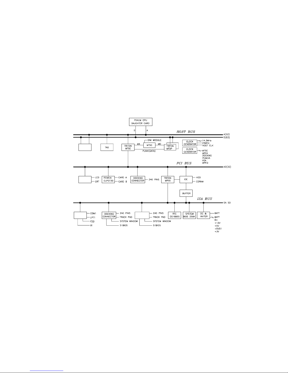
Figure 1-1 shows a functional block diagram of the notebook
computer. The following sections provide an overview of the
different functions.
CPU and Chip Set
The HiNote VP 500 series notebook computers use the Intel
P54CSLM 120/133 processors and P55C 150/166/175
processors mounted on a daughter card.
The following chip set is used to implement the core functions of
the syst em .
• Inte l Mo b i le Tr i to n chi p set p ro vi de s syst em co n tr ol l er &
PCI IDE controller functions
Overview
1-2
• SMC669FR provides support for floppy disk controller
(FDC), two serial ports (one serial port and one FIR) and
one parallel port
• Intel 80C51SL provides the keyboard controller and
scanner and the battery management unit
• Cirrus CL-PD6832 is used as the PCI PCMCIA controller
• ESS ES1878 for the audio subsystem
CACHE
RAM
Selected Models
VGA
NM2093
VGA
NM2093
AUDIO
ESS 1878
Figure 1-1. Functional Block Diagram

Overview
1-3
Memory
The syst em co m es w it h 16 M B o f on -board DRAM for system
memory and 256KB of L2 cache memory (on selected models).
System memory can be upgraded to a total of 24 MB, 32 MB, 48
MB, and 80 MB. The upgrade is performed by installing two 4 MB,
8 MB, 16 MB, or 32 MB DIMM modules. Two identical memory
modules must be installed when adding additional memory.
BIOS
The syst em h a s a 2 5 6K B F la sh R OM fo r syst em BI OS ( Phoenix
BIOS 4.04). The BIOS provides support for the following:
• Suspend to RAM/Disk
• Full APM 1.2 supported
• Password protection(System and HDD)
• Auto-configured with replicator/docking/modules
• Windows 95 ready with PnP
• 32KB ROM for 51SL keyboard controller
• Gas-gauge for battery status information
• Vari o u s ho t -ke ys fo r syste m con t ro l

Overview
1-4
Video Contr oller Chip
Video support is provided by the Neo Magic NM2093 VGA
Controller Chip. This chip provides the following functions:
• PCI Bus support
• Simultaneous display supported
• Integrated 128-bit wide, 7Mbits Display Memory – 1.1 MB
of Video RAM
• Integrated programmable linear address feature
accelerates GUI performance
• Supports NON-interlaced CRT monitors with resolutions
up to 1024 x 768/256 colors
• Advanced power management features minimize power
consumption during:
− Normal operation
− Standby mode
− SUSPEND mode
− VESA DPMS for monitor by 2093 (option)
• Graphic accelerator for WINDOWS application
• 3.3V/5V panel Interface support
− bit BLT Engine
− Memory mapped I/O
− Linear addressing
− Color expansion
− 64x64 hardware cursor
− 64x64 or 128x128 hardware ICON

Overview
1-5
• High resolution SVGA (800x600) panel
− TFT displays support a maximum of 64K colors
− DSTN displays support a maximum of 64K colors
I/O Ports
The syst em h a s th e fo l lo wi n g I / O po r ts:
• One 9 pin Serial port, 16550A compatible
• One 25 pin Parallel port, EPP/ECP Capability
• One 15 pin CRT port
• 6 pin external full keyboard/numeric key-pad / PS/2
mouse connector
• One microphone in port & one speaker out port
• 240 pin docking connector that supports PS2 mouse port,
AT-keyboard, 1S1P, CRT, audio ports, MIDI port, and AC
jack.
• Built-in microphone
• Built-in IRDA FIR tran smitte r-receiver
Option Modules
The following expansion modules can be installed in the system:
Secondary LiIon Battery
Components, C ontrols and Indicator s
This section shows the locations and provides a description of the
different components, controls, and indicators on your DIGITAL
notebook computer.
Overview
1-6
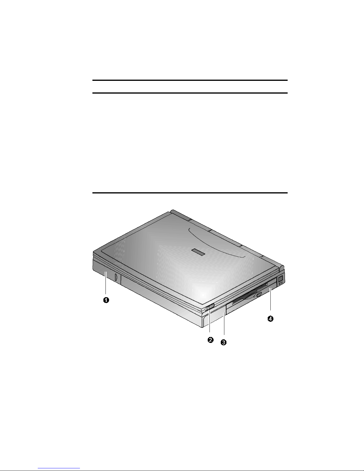
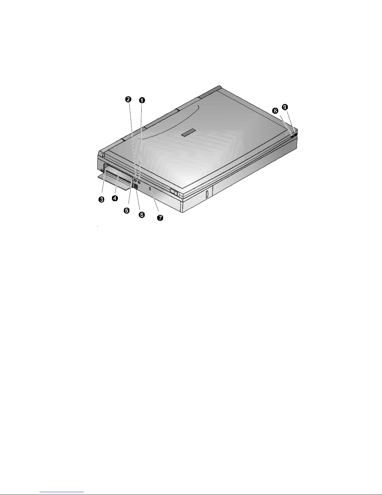
Front and S ide Com ponents (Pane l Clos ed)
Component Description
➊
Removable
Hard Drive
Easily removable and upgradable.
➋
Lid Release Slide the two latches located on either
side of the notebook toward you to open
the LCD panel.
➌
Main Battery
Module
Removable battery module that can be
replaced with a charged battery.
➍
Expansion bay Supports the 12X CD-ROM/FDD
Combination module and optional lithiumion secondary battery module.
Figure 1-2. Right Front View (Panel Closed)
Overview
1-7
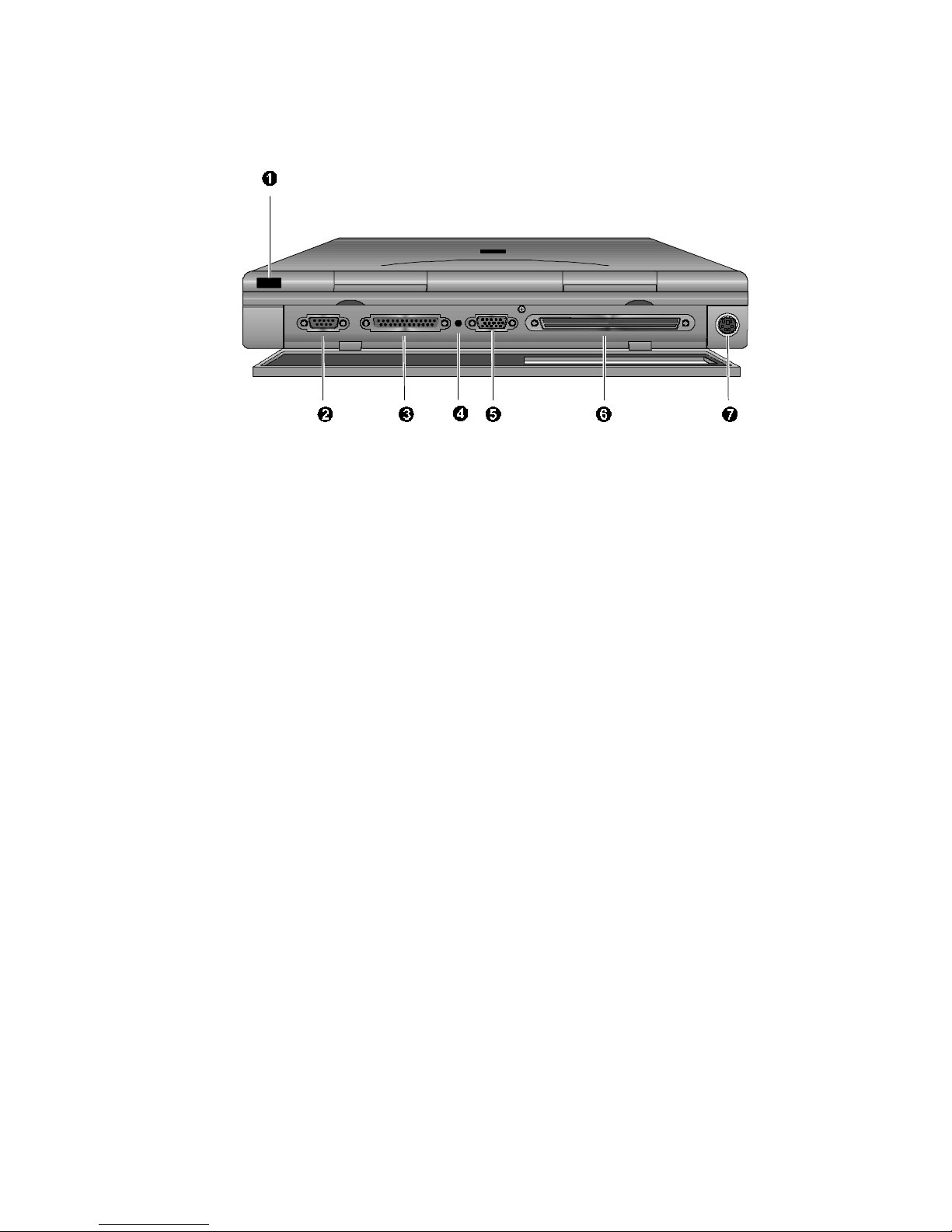
Rear View
Component Description
➊
Fast Infrared
Interface
Allows wireless data transfer between the
notebook and other IR devices.
(Selected models only)
➋
Serial (COM)
Port
A serial device connects to this port.
➌
Parallel LPT
Port
A parallel device, such as a printer,
connects to this port.
➍
Reset Button Using a pen or paper clip, press this
button to reboot the system. All unsaved
data will be lost.
➎
VGA Display
Port
An external VGA or SVGA monitor
connects to this port.
➏
Minidock Port This 240-pin port allows you to connect
the notebook to the Minidock Port
Replicator.
➐
External
Keyboard or
PS/2 Mouse
Port
An external keyboard or PS/2 mouse
connects to this port.
Overview
1-8
Figure 1-3. Rear View
Overview
1-9
Left a nd Side C omponents
Component Description
➊
Speaker-out
Port
External speakers or headphones
connect to this port.
➋
External Mic
Port
An external microphone connects to the
notebook.
➌
PC Card
Lower Socket
Eject Button
Ejects a PC Card Type II from the lower
socket or to eject a Type III card.
➍
PC Card
Socket
Insert PC Card Type II or Type III cards
into this socket.
➎
PC Card
Upper Socket
Eject Button
Ejects a PC Card Type II from the upper
socket..
➏
AC Power Port The AC Adapter power cord connects to
this port.
➐
Security Lock
Port
A Security Lock device, such a s a
Kensington Lock, connects to this port.
AC Power LED Lights green when the notebook is
operating on AC power.
Battery
Charger LED
Lights amber when the battery is being
charged. When the battery is fully
charged the amber LED turns off.
Overview
1-10
Figure 1-4. Left Front View (Panel Closed)

Overview
1-11
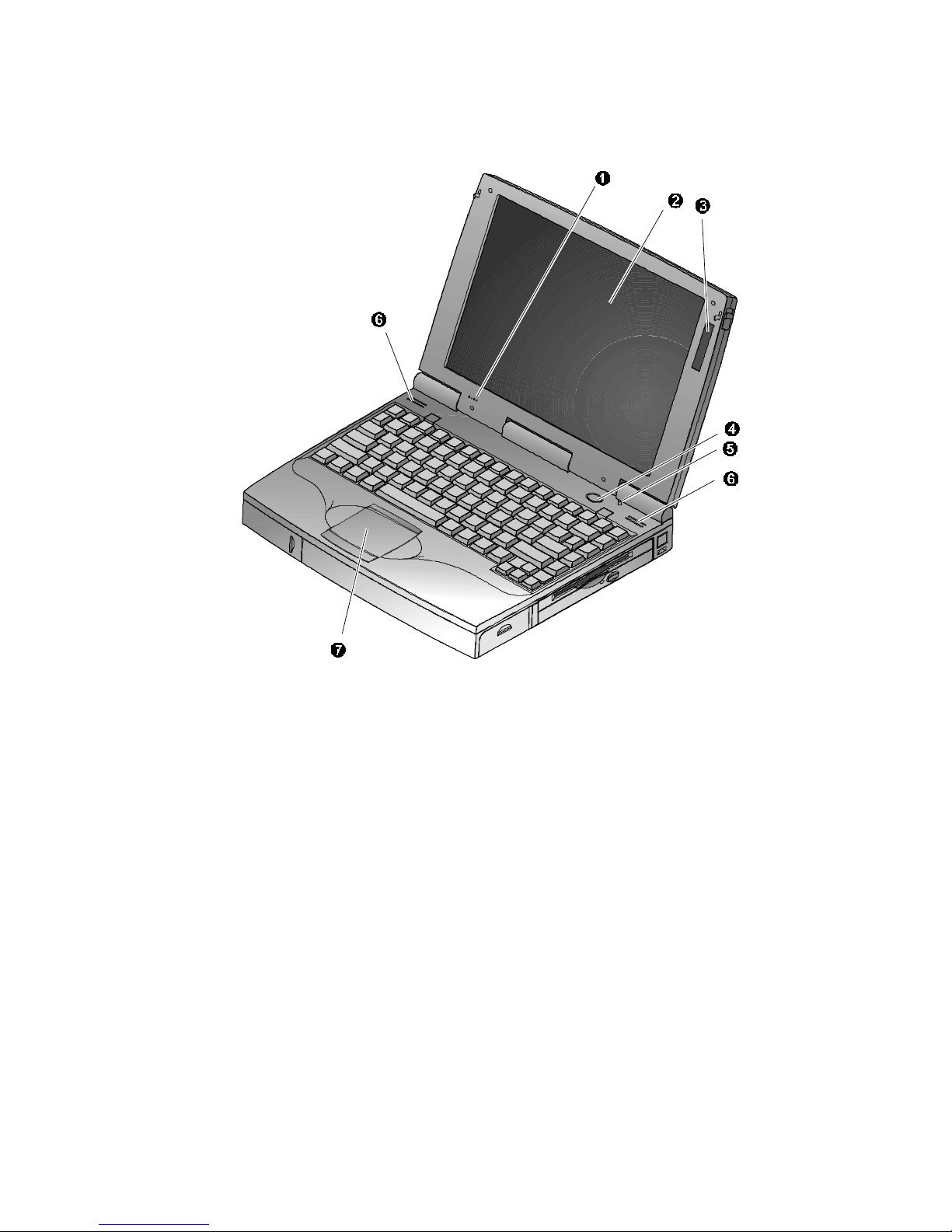
Right Front View (Pa nel Ope n)
Component Description
➊
Internal
Microphone
Used to record music, voice and sound
files.
➋
LCD Display DSTN or TFT Super VGA back-lit display.
➌
LCD Status
Display
Provides system operating status.
➍
Suspend/
Resume
Button
Turns the notebook on and toggles
between the suspend/resume mode.
Press [fn + Suspend/Resume] to turn off
the notebook.
➎
Lid Switch Close the notebook’s LCD lid to suspend
the system. Open the lid to resume the
normal operation. The Lid Switch can be
configured to CRT display mode from
within the Power menu of the BIOS Setup
Program. Please refer to Chapter 2.
➏
Internal Stereo
Speakers
Used to hear sound files and system
sounds through stereo speakers.
Touch pad A touch sensitive pointing device
providing all the functions of a two-button
mouse.
Overview
1-12
Figure 1-5. Right Front View (Panel open)
Overview
1-13
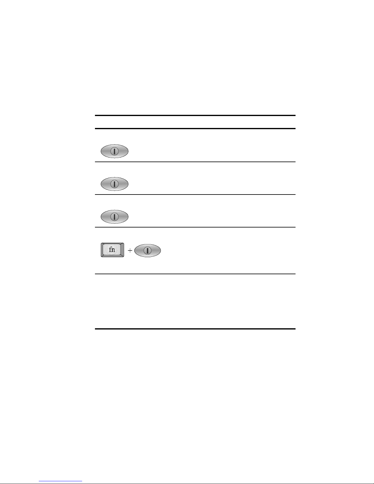
Controlling P ower
Unique to DIGITAL notebook’s, the suspend/resume button not
only enables you to take advantage of the built-in power saving
features but also turns the notebook on and off.
Action How to...
On Press the Suspend/Resume button to
turn the system on.
Suspend When the system is on, press this button
to place your system in Suspend mode.
Resume Press the Suspend/Resume button to
resume normal operation from the
Suspend mode.
Off To completely shut off your notebook,
press and hold [fn + suspend/resume]
button until a system beep sounds,
indicating that the system has been
successfully turned off.
Suspend
Lid Switch
In its factory default mode, closing the
LCD lid will also enter the notebook into
Suspend mode. Refer to Chapter 3, in
the section labeled
Power Menu
for
instructions on how to configure the Lid
Switch function.

Overview
1-14
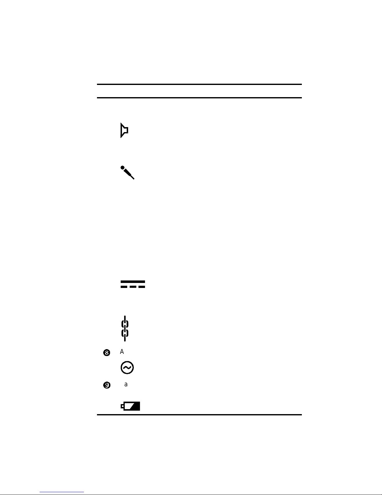
Battery Charge Gauge (in LCD Status Display)
Icon When Displayed, Indicates…
76% to 100% battery operating time remaining.
When the lines within this icon are rotating, it
indicates that the battery is being charged. When
the rotating stops, the battery is fully charged.
51% to 75% battery operating time remaining.
26% to 50% battery operating time remaining.
Low battery to 25% battery operating time
remaining. The system’s wa rning beep will sound.
Save your work, replace the low battery with a
fully charged one or use an AC power source to
run the notebook. The [fn + F7] keys shut off the
warning beep. It also mutes all audio.
System has ceased charging the battery. An
abnormal condition exists causing the core of the
battery to reach its maximum temperature and
battery charging has been suspended..
Overview
1-15
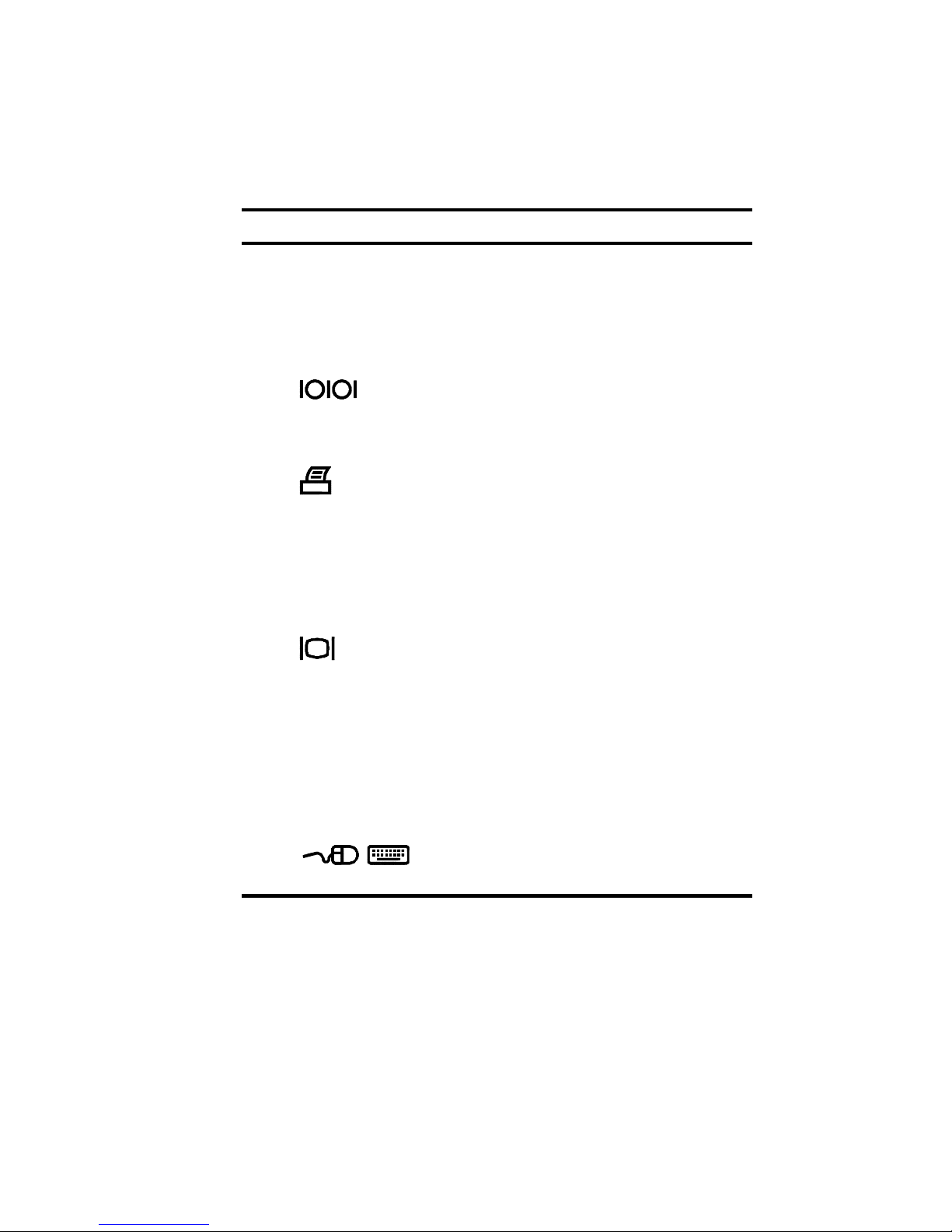
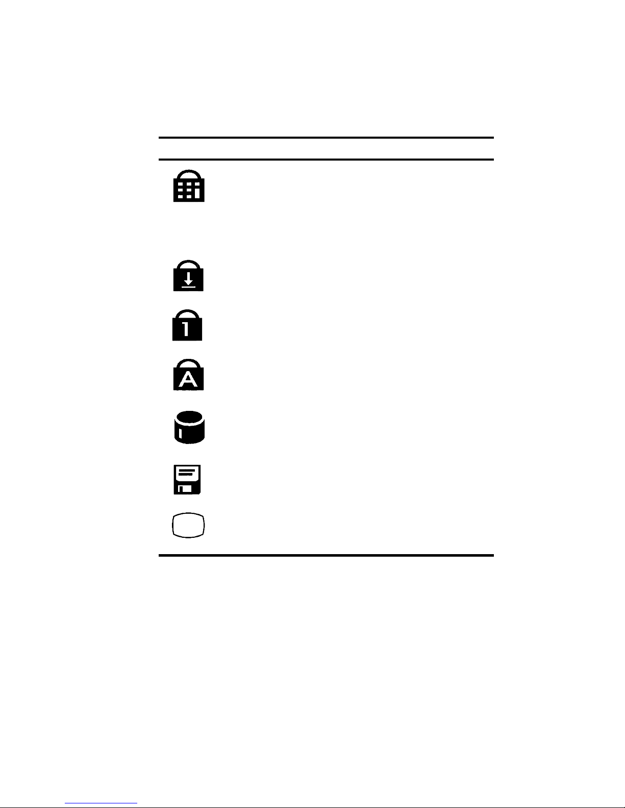
LCD St atus D ispla y
Icon When Displayed Indicates...
Embedded Numeric Keypad is enabled by the hot
key combination. The keyboard’s embedded
keypad functions as a cursor control keypad.
When displayed in conjunction with the Num Lock
icon, the embedded keypad functions as a
numeric keypad.
Scroll Lock is enabled by a hot key combination.
Num Lock is enabled by a hot key combination.
Caps Lock is enabled.
Hard Disk Drive/CD-ROM is being accessed by
the system.
Floppy Disk Drive is being accessed by the
system.
The external monitor (CRT) or Simul mode is
enabled. If the icon is blinking, the system is in
Save to RAM mode.

Overview
1-16
Keyboard Hot Keys
Hot keys are activated by holding down the [fn] key (located in the
lower left corner of the keyboard) and pressing the desired function
key.
[fn] + Function
[fn + esc] Places the computer in Standby Mode.
[fn+A] Places the computer in Save to RAM Mode.
[fn+F] All open data and system settings are Saved to
Disk.
[fn + F1] Decreases brightness level.
[fn + F2] Increases brightness level.
[fn + F4] Switches between the three display modes:
1. LCD Display
2. LCD Display and External Monitor
3. External Monitor only
Each time you press this hot key combination the
computer changes to the next display mode.
[fn + F5] Decreases the display contrast (DSTN screens
only).
[fn + F6] Increases the display contrast (DSTN screens
only).
[fn + F7] Enables or disables audio/speaker output
including system beep indicating low battery.
[fn + F8] Toggles the keyboard’s embedded key pad on
and off. When used by itself, it functions as a
cursor control keypad. Press [fn+F9] and then
the [fn+F8] hot key combination to use the
notebook’s numeric embedded keypad.
continued

Overview
1-17
[fn] + Function
[fn + F9] Toggles Num Lock on and off. Used by itself,
fn+F9 enables an external keyboard numeric
keypad.
[fn + F10] Toggles Scroll Lock on and off. The Scroll Lock
functions in certain applications, leaving the
cursor in its current position while moving the
screen in the direction of the arrow pressed.
[fn +
home/pause]
Pauses the display output. Press a key to
resume.
[fn +
end/break]
If Break is enabled, pressing this hot key sends a
system break.
[fn + PrScr/
SysReq]
Determined by application software.
[fn + ↑] Increases the audio volume.
[fn + ↓] Decreases the audio volume.

Overview
1-18
Related Inform ation
Documentation
DIGITAL HiNote VP
550, VP 575 Series
User’s Guide
English
French
Italian
German
Spanish
Japanese
Simple Chinese
ER-PD1WF-UA
ER-PD1WF-UP
ER-PD1WF-UI
ER-PD1WF-UG
ER-PD1WF-US
ER-PD1WF-UJ
ER-PD1WF-U2
DIGITAL HiNote VP
550, VP 575 Series
Quick R eference
Card
English
French
Italian
German
Spanish
Japanese
Simple Chinese
ER-PD1WF-BA
ER-PD1WF-BP
ER-PD1WF-BI
ER-PD1WF-BG
ER-PD1WF-BS
ER-PD1WF-BJ
ER-PD1WF-B2
Quick Setup Guide English, French,
Italian, German,
Spanish,
Japanese
ER-PD1WF-IM
English, Dutch,
Danish, Swedish,
Norwegian,
Finnish
ER-PD1WF-IX
English, Simple
Chinese
ER-PD1WF-I2

Overview
1-19
AC Adapter Bulletin English, French,
Italian, German,
Spanish,
Japanese
ER-PB1WF-DM
DIGITAL HiNote
System CD
AG-R49UA-BE
World Wide We b
Information such as drivers, BIOS updates, and on-line
documentation is available from DIGITAL’s World Wide Web Site.
The URL for the site is:
HTTP://WWW.WINDOWS.DIGITAL.COM/

2-1
System Restoration
2
Introduction
This chapter provides information on how to restore the operating
system and drivers on a DIGITAL HiNote VP 500 series notebook
computer. It provides instructions on how to create a bootable
floppy for the system and how to restore the syste m u si n g t h e
bootable floppy or the DIGITAL HiNote System CD.
CAUTION
: Do not compress the boot drive
using compression utilities. It will cause the
notebook computer’s Save to File feature to not
function properly.

System Restoration
2-2
Reinstalling and Installing Drivers
Reinstalling Drivers –
The procedures for reinstalling certain
drivers over an existing installation is different than installing the
drivers on a clean installation. For information on how to reinstall
drivers, refer to the latest version of the DIGITAL HiNote System
CD.
Installing Drivers –
In o rd e r t o re sto r e t h e syst e m ba ck t o i t s
original DIGITAL factory shipped configuration, you must install the
HiNote VP 500 Series audio, video, track pad and network drivers
(the need to install the network driver depends upon the individual
requirements). If you have installed WinNT, you will also want to
install the EPM (Enhanced Power Management) driver located in
the Driver/WinNT directory. Please refer to Chapter 5 of the
User’s Guide in the section labeled
Installing PC Cards in WinNT
4.0
, for information on EPM features. These drivers are located on
the DIGITAL HiNote System CD. To install any of these drivers,
please refer to the following instructions:
1. Boot to Windows.
2. In sert th e DI GITAL HiNo te Syste m CD i nto th e CD-ROM
drive.
3. From the Taskbar, click on Start and then Run. In the
Run command box type X:\CDInstall (X represents the
drive letter of the CD-ROM).
4. At the Welcome screen, click on Next. Then at the Install
screen, click on Driver Installation Instructions.
5. Select the driver(s) you wish to install. A README.TXT
file will appear. Print the file(s). These are the installation
instructions to install the selected drivers(s).

System Restoration
2-3
Creating a B ootable Floppy
To create a bootable floppy, perform the following:
1. Boot to Windows. Insert the DIGITAL HiNote System CD
into the CD-ROM drive. Click on Start and then Run. In
the Run dialog box command line type X:\CDInstall
(X: represents the drive letter of the CD-ROM).
2. Click through the Welcome screens until the Install Menu
appears.
3. Click on the Utilities box and then click on Next.
4. Click on Create Boot Floppy and click on Next. Click on
Next again.
5. Insert a 3½ inch 1.44 MB floppy into the floppy disk drive.
Follow the on-screen instructions. The utility
(Sysboot.exe) will format the floppy, make the floppy
bootable and copy appropriate syste m f i le s t o t h e f l oppy.
Before creating the boot floppy, ensure that the floppy is
NOT write protected. Any previous data on the diskette
will be erased.
6. After the bootable floppy has been created, ensure that it
is write protected. Paste a label onto the diskette and
label it HiNote VP 500 Series Bootable Floppy.
Using the Boot Floppy
The h ar d dr ive i n th e syste m ha s been partitioned using the FDISK
utility. The hard drive has also been formatted. A
"SAVETOFILE.BIN" file has been created for the system b y usi n g
PHDISKF. Without Save-to-File.bin, it will not be possible to take
advantage of the system' s Sa ve to Di sk p o we r m anagement
feature.
FDISK, format and PHDISKF are located on both the DIGITAL
HiNote System CD and the bootable floppy, which can be created
from the DIGITAL HiNote System CD.

System Restoration
2-4
Re-installing the Operating S ystem
To re-install the Windows Operating System on top of the current
Operating System, perform the following:
1. Insert the bootable floppy into the floppy disk drive.
Powe r on t he syst em . A l i st o f ch o i ces appear.
NOTE
: To exit this menu and go to a DOS prompt,
press 2. To re-enter this menu from a DOS prompt,
type AUTOEXEC and press the Enter key.
AUTOEXEC must be typed from the A: prompt.
2. Insert the Microsoft Operating System CD into the CDROM drive.
3. From the bootable floppy Main Menu, choose Option 3
(Re-install).
4. Follow Microsoft's on-screen instructions.
5. Remove the Microsoft Operating System CD and insert
the DI GITAL HiNo te System CD. Ru n CDIn sta ll. Cli ck
on the Next buttons until the Main Install screen appears.
6. Click on Enhancements and Updates, and then click on
Next. Follow the on-screen instructions. These
enhancements update the Microsoft Operating syste m.
7. After re-installing the Operating System you should reinstall all drivers. Please refer to the section on
Reinstalling/Installing Drivers for information on installation
procedures.
 Loading...