

Page 1

dt
VT520/VT525VideoTerminal
ProgrammerInformation
Order Number: EK-VT520-RM. A01
Page 2

July 1994
Digital Equipment Corporation makes no representations that the use of its products in the
manner described in this publication will not infringe on existing or future patent rights, nor do
the descriptions contained in this publication imply the granting of licenses to make, use, or sell
equipment or software in accordance with the description.
DEC, OpenVMS, VT, and the DIGITAL logo are trademarks of Digital Equipment Corporation.
ADDS is a trademark of Applied Digital Data Systems, Inc.
IBM, ProPrinter, and PS/2 are registered trademarks of International Business Machines
Corporation.
MS–DOS is a registered trademark and Windows is a trademark of Microsoft Corporation.
SCO is a trademark of Santa Cruz Operations, Inc.
TVI is a trademark of TeleVideo, Inc.
UNIX is a registered trademark of UNIX System Laboratories, Inc.
WY and WYSE are registered trademarks of Wyse Technologies.
All other trademarks and registered trademarks are the property of their respective holders.
The Energy Star emblem does not represent EPA endoresement of any product or service.
Copyright © Digital Equipment Corporation 1994. All Rights Reserved.
Printed in U.S.A.
For copies of manuals, contact your local sales office.
This document was prepared using VAX DOCUMENT Version 2.1.
Page 3

Introduction
This manual provides detailed information for advanced users, consultants, and
programmers. This manual has the following parts, chapters, and appendices:
• Part I, VT520 Video Terminal
• Part II, VT520 ANSI Mode
Preface
• Chapter 1, Overview
• Chapter 2, Set-Up
• Chapter 3, Desktop Features
• Chapter 4, ANSI Control Functions Summary
• Chapter 5, ANSI Control Functions
• Chapter 6, SCO Console Emulation
• Chapter 7, Character Sets
• Chapter 8, Keyboard Processing
• Chapter 9, Communications
• Chapter 10, Printer Port
• Part III, VT520 ASCII Emulation
• Chapter 11, ASCII Emulations and Control Functions
• Chapter 12, ASCII Escape Sequences
• Chapter 13, Defining and Loading ASCII Character Fonts
• Appendix A, VT Keyboard Legend Data
• Appendix B, Enhanced PC Keyboards
• Appendix C, ASCII Keycodes and Local Functions
• Appendix D, VT520 Termcap Data
• Appendix E, ANSI Control Function Index
iii
Page 4

Conventions
The following conventions are used in this manual:
Set-Up features Terminal Set-Up menu selections appear in boldface type.
Alt/Ctrl/Print Screen
Characters in control
functions
Parameters Parameters appear in italic type.
Note Provides general information.
How to Use This Manual
The VT520 Video Terminal Programmer Information is written for four audiences:
an advanced user, who needs to know more about the terminal Set-Up features;
a programmer, who develops application programs; a software product support
person, who provides assistance to application programmers and users; and a
hardware systems engineer, who need more information on terminal connections.
Advanced User
If you have read the VT520 Video Terminal Installation and Operating
Information manual and need more information on the the terminal Set-Up
features, you may wish to refer to the following:
Multiple keys are separated by a slash (/) and should be
pressed in combination. That is, all three keys
Print Screen
Control function characters are in boldface type. Below
each character is a column/row number that indicates the
character’s position in a standard code table. For example:
ESC # 6
1/11 2/3 3/6
are pressed down at the same time.
(
=
Control function
(
=
Column/row numbers
Alt,Ctrl
, and
• Index
• Chapter 1—Overview—Provides a brief summary of the product.
• Chapter 2—Set-Up—Describes each entry in the Set-Up menus in the order
that is displayed in the terminal.
• Chapter 3—Desktop Features—Provides a more in-depth description of the
desktop features of the terminal.
• Chapter 6—Keyboard Processing—Describes the differences in the types
of keyboard layouts supported, local functions, and accessibility aids.
Programmer
If you are using ANSI control functions for your program, then you may wish to
start with Part II of the manual:
• Chapter 4—ANSI Control Function Summary— Provides a tutorial
section on Control Functions and information on designing and down-line
loading a Soft Character set (soft font). In this chapter, the Control Functions
are grouped according to the task to be performed. The information on each
Control Function is very brief. If you need more information, the mnemonic
at the end of the line item refers to a command section in Chapter 5.
• Chapter 5—ANSI Control Functions—Provides in-depth information on
each control function listed in alphabetic order according to the mnemonic.
• Chapter 2—Set-Up—Lists the Set-Up factory defaults at the end of this
chapter, with their host control code mnemonic.
iv
Page 5

• Chapter 6—Keyboard Processing—Describes the keyboard layouts,
keyboard-to-host interface, keypad sequences, local functions, LEDs controls,
languages, accents, scan codes, and control codes.
• Chapter 9—Communications—Describes the serial communications from
the terminal to the host ports and the hardware and software handshaking.
• Chapter 10—Printer Port—Describes the parallel printer port and the
switching sequences for the modes supported.
• Appendix A—VT Keyboard Legend Data
• Appendix B—Enhanced PC Keyboard Legend Data
• Appendix D—VT500 Termcap Data
If you are developing a application program for a SCO Console, then you may
wish to refer to:
• Chapter 6—SCO Console Emulation—Describes the SCO Console mode,
including the Control Functions relative to the SCO Console applications.
If you are using ASCII control functions for your program, then you may wish to
start with Part III of the manual:
• Chapter 11—ASCII Emulations and Control Functions— Provides an
overview of the ASCII emulation, the coding notation, and the symbols used
in the ASCII sequence tables.
• Chapter 12—ASCII Escape Sequences—Summarizes the ASCII escape
and control sequences for the various ASCII emulation modes, according to
the task to be performed.
• Chapter 13—Defining and Loading ASCII Character Fonts – Provides
specific information on loading font banks and designing an ASCII character
font.
• Appendix C—ASCII Keycodes and Local Functions
Software Product Support
If you are helping a user or programmer with an application, then you may wish
to refer to the following:
• Appendix E—ANSI Control Function Index—Lists the control functions
by their final character, which makes them easier to find in a program. The
mnemonic at the end of the line item refers to a command in Chapter 5, listed
in alphabetic order.
• Index—Lists control functions by mnemonic or by name and lists other
subjects by topic.
• Chapter 5—ANSI Control Functions—Provides in-depth information on
specific control functions.
• Chapter 6—Keyboard Processing—Lists the scan codes Make and Break
sequences.
• Appendix D—VT500 Termcap Data—Provides the Termcap information for
ANSI emulations.
v
Page 6

Hardware Systems Engineer
If you are helping a user to install the terminal or to operate within a specific
environment, then you may wish to refer to the following:
• Index—Search by topic.
• Chapter 1—Overview Provides a brief summary of the product.
• Chapter 2—Set-Up Describes each entry in the order that is displayed in
the terminal, starting with the Actions menu and lists the modes supported.
Also lists the Set-Up factory defaults.
• Chapter 9—Communications—Describes the serial communications from
the terminal to the host ports, pin numbers and signals, and the hardware
and software handshaking.
• Chapter 10—Printer Port—Describes the parallel printer port, pin numbers
and signals, and modes supported.
vi
Page 7

Contents
Preface . . . . . . . . . . . . . . . . . . . . . . . . . . . . . . . . . . . . . . . . . . . . . . . . . . . . . . . . . . . . iii
Part I VT520 Video Terminal
1 Overview
1.1 Introduction . . . . . . . . . . . . . . . . . . . . . . . . . . . . . . . . . . . . . . . . . . . . . . . . 1–1
1.2 Communications Features . . . . . . . . . . . . . . . . . . . . . . . . . . . . . . . . . . . . . 1–1
1.3 Keyboard Features . . . . . . . . . . . . . . . . . . . . . . . . . . . . . . . . . . . . . . . . . . . 1–2
1.4 Printer Port Features . . . . . . . . . . . . . . . . . . . . . . . . . . . . . . . . . . . . . . . . . 1–3
1.5 Display and Text Capabilities . . . . . . . . . . . . . . . . . . . . . . . . . . . . . . . . . . 1–3
1.5.1 ANSI . . . . . . . . . . . . . . . . . . . . . . . . . . . . . . . . . . . . . . . . . . . . . . . . . . 1–3
1.5.2 ASCII . . . . . . . . . . . . . . . . . . . . . . . . . . . . . . . . . . . . . . . . . . . . . . . . . . 1–3
1.6 Enhanced Set-Up . . . . . . . . . . . . . . . . . . . . . . . . . . . . . . . . . . . . . . . . . . . . 1–4
1.7 Desktop Productivity Features . . . . . . . . . . . . . . . . . . . . . . . . . . . . . . . . . . 1–4
1.8 Character Set Support . . . . . . . . . . . . . . . . . . . . . . . . . . . . . . . . . . . . . . . . 1–4
1.9 Ergonomics (Human Factors) Features . . . . . . . . . . . . . . . . . . . . . . . . . . . 1–4
1.10 Field-Upgradable Firmware . . . . . . . . . . . . . . . . . . . . . . . . . . . . . . . . . . . . 1–5
1.11 Comparison with previous VT Terminals . . . . . . . . . . . . . . . . . . . . . . . . . . 1–6
2 Set-Up
2.1 Entering Set-Up . . . . . . . . . . . . . . . . . . . . . . . . . . . . . . . . . . . . . . . . . . . . . 2–1
2.1.1 Effects of Entering Set-Up . . . . . . . . . . . . . . . . . . . . . . . . . . . . . . . . . . 2–2
2.1.2 Set-Up Languages . . . . . . . . . . . . . . . . . . . . . . . . . . . . . . . . . . . . . . . . 2–2
2.1.3 Power-On Settings and Defaults . . . . . . . . . . . . . . . . . . . . . . . . . . . . . 2–2
2.1.4 Self-test Error Messages . . . . . . . . . . . . . . . . . . . . . . . . . . . . . . . . . . . 2–3
2.1.5 Context Sensitivity. . . . . . . . . . . . . . . . . . . . . . . . . . . . . . . . . . . . . . . . 2–3
2.1.6 Set-Up Summary Line . . . . . . . . . . . . . . . . . . . . . . . . . . . . . . . . . . . . . 2–5
2.1.7 Set-Up Status Messages. . . . . . . . . . . . . . . . . . . . . . . . . . . . . . . . . . . . 2–5
2.1.8 Status Line . . . . . . . . . . . . . . . . . . . . . . . . . . . . . . . . . . . . . . . . . . . . . 2–6
2.1.9 Keyboard Indicator Line . . . . . . . . . . . . . . . . . . . . . . . . . . . . . . . . . . . 2–6
2.2 Set-Up Screen Text . . . . . . . . . . . . . . . . . . . . . . . . . . . . . . . . . . . . . . . . . . 2–7
2.3 Main Menu . . . . . . . . . . . . . . . . . . . . . . . . . . . . . . . . . . . . . . . . . . . . . . . . 2–8
2.3.1 On-Line . . . . . . . . . . . . . . . . . . . . . . . . . . . . . . . . . . . . . . . . . . . . . . . . 2–8
2.3.2 Save Settings . . . . . . . . . . . . . . . . . . . . . . . . . . . . . . . . . . . . . . . . . . . . 2–9
2.3.3 Restore Settings . . . . . . . . . . . . . . . . . . . . . . . . . . . . . . . . . . . . . . . . . . 2–9
2.3.4 Exit Set-Up . . . . . . . . . . . . . . . . . . . . . . . . . . . . . . . . . . . . . . . . . . . . . 2–9
2.4 Actions Menu . . . . . . . . . . . . . . . . . . . . . . . . . . . . . . . . . . . . . . . . . . . . . . . 2–9
2.4.1 Clear Display . . . . . . . . . . . . . . . . . . . . . . . . . . . . . . . . . . . . . . . . . . . . 2–9
2.4.2 Clear Communications . . . . . . . . . . . . . . . . . . . . . . . . . . . . . . . . . . . . . 2–9
2.4.3 Reset this Session . . . . . . . . . . . . . . . . . . . . . . . . . . . . . . . . . . . . . . . . 2–10
2.4.4 Restore Factory Defaults . . . . . . . . . . . . . . . . . . . . . . . . . . . . . . . . . . . 2–10
2.4.5 Clock, Calculator, Show Character Sets . . . . . . . . . . . . . . . . . . . . . . . . 2–11
vii
Page 8

2.4.6 Banner Message . . . . . . . . . . . . . . . . . . . . . . . . . . . . . . . . . . . . . . . . . . 2–11
2.5 Multiple Sessions . . . . . . . . . . . . . . . . . . . . . . . . . . . . . . . . . . . . . . . . . . . . 2–11
2.5.1 Enabling and Controlling the Session Configuration . . . . . . . . . . . . . . 2–12
2.5.2 Multiple Sessions using a Terminal Server with TD/SMP . . . . . . . . . . 2–12
2.5.3 Multiple Sessions using SSU Host Software . . . . . . . . . . . . . . . . . . . . 2–12
2.5.4 Opening Another Session . . . . . . . . . . . . . . . . . . . . . . . . . . . . . . . . . . . 2–12
2.5.5 Restoring an Interrupted Session . . . . . . . . . . . . . . . . . . . . . . . . . . . . . 2–13
2.5.6 Session Management . . . . . . . . . . . . . . . . . . . . . . . . . . . . . . . . . . . . . . 2–13
2.6 Session Menu . . . . . . . . . . . . . . . . . . . . . . . . . . . . . . . . . . . . . . . . . . . . . . . 2–13
2.6.1 Select Session. . . . . . . . . . . . . . . . . . . . . . . . . . . . . . . . . . . . . . . . . . . . 2–14
2.6.2 Session Name . . . . . . . . . . . . . . . . . . . . . . . . . . . . . . . . . . . . . . . . . . . . 2–14
2.6.3 Pages per Session. . . . . . . . . . . . . . . . . . . . . . . . . . . . . . . . . . . . . . . . . 2–14
2.6.4 Soft Character Sets/Session . . . . . . . . . . . . . . . . . . . . . . . . . . . . . . . . . 2–16
2.6.5 Save Settings for All and Restore Settings for All . . . . . . . . . . . . . . . . 2–16
2.6.6 Copy Settings from Menu. . . . . . . . . . . . . . . . . . . . . . . . . . . . . . . . . . . 2–17
2.6.7 Update Session . . . . . . . . . . . . . . . . . . . . . . . . . . . . . . . . . . . . . . . . . . 2–17
2.7 Resetting and Restoring Defaults. . . . . . . . . . . . . . . . . . . . . . . . . . . . . . . . 2–18
2.7.1 Reset Session . . . . . . . . . . . . . . . . . . . . . . . . . . . . . . . . . . . . . . . . . . . . 2–18
2.7.2 Restore Factory Defaults . . . . . . . . . . . . . . . . . . . . . . . . . . . . . . . . . . . 2–18
2.8 Display Menu . . . . . . . . . . . . . . . . . . . . . . . . . . . . . . . . . . . . . . . . . . . . . . . 2–19
2.8.1 Lines per Screen . . . . . . . . . . . . . . . . . . . . . . . . . . . . . . . . . . . . . . . . . 2–20
2.8.1.1 Auto Resize . . . . . . . . . . . . . . . . . . . . . . . . . . . . . . . . . . . . . . . . . . 2–20
2.8.2 Lines per Page . . . . . . . . . . . . . . . . . . . . . . . . . . . . . . . . . . . . . . . . . . . 2–20
2.8.3 Review Previous Lines Buffer . . . . . . . . . . . . . . . . . . . . . . . . . . . . . . . 2–21
2.8.4 Columns per Page, Clear on Change . . . . . . . . . . . . . . . . . . . . . . . . . . 2–22
2.8.5 Status Display . . . . . . . . . . . . . . . . . . . . . . . . . . . . . . . . . . . . . . . . . . . 2–22
2.8.6 Scrolling Mode . . . . . . . . . . . . . . . . . . . . . . . . . . . . . . . . . . . . . . . . . . . 2–22
2.8.7 Screen Background . . . . . . . . . . . . . . . . . . . . . . . . . . . . . . . . . . . . . . . 2–22
2.8.8 Cursor Display . . . . . . . . . . . . . . . . . . . . . . . . . . . . . . . . . . . . . . . . . . . 2–22
2.8.9 Cursor Coupling . . . . . . . . . . . . . . . . . . . . . . . . . . . . . . . . . . . . . . . . . . 2–22
2.8.10 Writing Direction . . . . . . . . . . . . . . . . . . . . . . . . . . . . . . . . . . . . . . . . . 2–23
2.8.11 Zero . . . . . . . . . . . . . . . . . . . . . . . . . . . . . . . . . . . . . . . . . . . . . . . . . . . 2–23
2.8.12 Auto Wrap . . . . . . . . . . . . . . . . . . . . . . . . . . . . . . . . . . . . . . . . . . . . . . 2–23
2.8.13 New Line Mode . . . . . . . . . . . . . . . . . . . . . . . . . . . . . . . . . . . . . . . . . . 2–23
2.8.14 Lock User Preferences . . . . . . . . . . . . . . . . . . . . . . . . . . . . . . . . . . . . . 2–23
2.8.15 Show Control Characters . . . . . . . . . . . . . . . . . . . . . . . . . . . . . . . . . . . 2–24
2.8.16 CRT Saver . . . . . . . . . . . . . . . . . . . . . . . . . . . . . . . . . . . . . . . . . . . . . . 2–24
2.8.17 Energy Saver . . . . . . . . . . . . . . . . . . . . . . . . . . . . . . . . . . . . . . . . . . . . 2–24
2.8.17.1 Warning Bell . . . . . . . . . . . . . . . . . . . . . . . . . . . . . . . . . . . . . . . . . 2–25
2.8.18 Overscan . . . . . . . . . . . . . . . . . . . . . . . . . . . . . . . . . . . . . . . . . . . . . . . 2–25
2.8.19 Framed Windows . . . . . . . . . . . . . . . . . . . . . . . . . . . . . . . . . . . . . . . . . 2–25
2.8.20 Screen Alignment. . . . . . . . . . . . . . . . . . . . . . . . . . . . . . . . . . . . . . . . . 2–27
2.9 Color Set-Up . . . . . . . . . . . . . . . . . . . . . . . . . . . . . . . . . . . . . . . . . . . . . . . 2–28
2.9.1 Assign Colors . . . . . . . . . . . . . . . . . . . . . . . . . . . . . . . . . . . . . . . . . . . . 2–28
2.9.2 Alternate Text Colors . . . . . . . . . . . . . . . . . . . . . . . . . . . . . . . . . . . . . . 2–30
2.9.3 Define Colors Dialog Box . . . . . . . . . . . . . . . . . . . . . . . . . . . . . . . . . . . 2–31
2.9.4 Select Color Mode . . . . . . . . . . . . . . . . . . . . . . . . . . . . . . . . . . . . . . . . 2–32
2.9.5 ASCII Color Mode . . . . . . . . . . . . . . . . . . . . . . . . . . . . . . . . . . . . . . . . 2–32
2.9.6 Bold and Blink Style . . . . . . . . . . . . . . . . . . . . . . . . . . . . . . . . . . . . . . 2–32
2.9.7 Erase Color . . . . . . . . . . . . . . . . . . . . . . . . . . . . . . . . . . . . . . . . . . . . . 2–32
2.9.8 Reverse and Blank Attributes . . . . . . . . . . . . . . . . . . . . . . . . . . . . . . . 2–33
2.9.9 Intensity Attributes . . . . . . . . . . . . . . . . . . . . . . . . . . . . . . . . . . . . . . . 2–33
2.10 Terminal Type Menu . . . . . . . . . . . . . . . . . . . . . . . . . . . . . . . . . . . . . . . . . 2–33
2.10.1 Emulation Mode. . . . . . . . . . . . . . . . . . . . . . . . . . . . . . . . . . . . . . . . . . 2–33
viii
Page 9

2.10.2 Terminal ID to Host . . . . . . . . . . . . . . . . . . . . . . . . . . . . . . . . . . . . . . . 2–34
2.10.3 VT Default Character Set . . . . . . . . . . . . . . . . . . . . . . . . . . . . . . . . . . 2–34
2.10.4 PCTerm Character Set . . . . . . . . . . . . . . . . . . . . . . . . . . . . . . . . . . . . . 2–34
2.10.5 7-Bit NRCS Characters . . . . . . . . . . . . . . . . . . . . . . . . . . . . . . . . . . . . 2–34
2.10.6 Transmit 7-Bit Controls . . . . . . . . . . . . . . . . . . . . . . . . . . . . . . . . . . . . 2–34
2.11 ASCII Emulation Menu . . . . . . . . . . . . . . . . . . . . . . . . . . . . . . . . . . . . . . . 2–35
2.12 Keyboard Menu . . . . . . . . . . . . . . . . . . . . . . . . . . . . . . . . . . . . . . . . . . . . . 2–36
2.12.1 Keyboard Language . . . . . . . . . . . . . . . . . . . . . . . . . . . . . . . . . . . . . . . 2–37
2.12.2 Define Key Editor . . . . . . . . . . . . . . . . . . . . . . . . . . . . . . . . . . . . . . . . 2–37
2.12.2.1 Copy of Key Default—Moving a Standard Function . . . . . . . . . . . . 2–38
2.12.2.2 Customization . . . . . . . . . . . . . . . . . . . . . . . . . . . . . . . . . . . . . . . . 2–39
2.12.2.3 Modifier Keys . . . . . . . . . . . . . . . . . . . . . . . . . . . . . . . . . . . . . . . . . 2–39
2.12.2.4 Creating a New Function . . . . . . . . . . . . . . . . . . . . . . . . . . . . . . . . 2–39
2.12.2.5 Examples of Creating New Functions . . . . . . . . . . . . . . . . . . . . . . 2–39
2.12.2.6 Correcting a Mistake . . . . . . . . . . . . . . . . . . . . . . . . . . . . . . . . . . . 2–40
2.12.2.7 Creating A New Alphanumeric Key or Keyboard Layout . . . . . . . . 2–40
2.12.2.8 Examples of Creating New Alphanumeric Keys . . . . . . . . . . . . . . . 2–40
2.12.2.9 User-Defined Keys . . . . . . . . . . . . . . . . . . . . . . . . . . . . . . . . . . . . . 2–41
2.12.2.10 Programming Notes . . . . . . . . . . . . . . . . . . . . . . . . . . . . . . . . . . . . 2–41
2.12.3 Save Key Definitions . . . . . . . . . . . . . . . . . . . . . . . . . . . . . . . . . . . . . . 2–42
2.12.4 Recall Key Definitions . . . . . . . . . . . . . . . . . . . . . . . . . . . . . . . . . . . . . 2–42
2.12.5 Lock Key Definitions . . . . . . . . . . . . . . . . . . . . . . . . . . . . . . . . . . . . . . 2–42
2.12.6 Caps Lock Function . . . . . . . . . . . . . . . . . . . . . . . . . . . . . . . . . . . . . . . 2–42
2.12.7 Keyclick, Warning Bell, and Margin Bell Volume. . . . . . . . . . . . . . . . . 2–42
2.12.7.1 Visible Bell . . . . . . . . . . . . . . . . . . . . . . . . . . . . . . . . . . . . . . . . . . . 2–43
2.12.8 Keyboard Encoding . . . . . . . . . . . . . . . . . . . . . . . . . . . . . . . . . . . . . . . 2–43
2.12.9 Auto Repeat . . . . . . . . . . . . . . . . . . . . . . . . . . . . . . . . . . . . . . . . . . . . . 2–43
2.12.10 Data Processing Keys . . . . . . . . . . . . . . . . . . . . . . . . . . . . . . . . . . . . . . 2–43
2.12.11 Application Cursor Keys . . . . . . . . . . . . . . . . . . . . . . . . . . . . . . . . . . . 2–43
2.12.12 Application Keypad Mode . . . . . . . . . . . . . . . . . . . . . . . . . . . . . . . . . . 2–44
2.12.13 Map PC Keyboard to VT . . . . . . . . . . . . . . . . . . . . . . . . . . . . . . . . . . . 2–44
2.12.14 Ignore Missing Keyboard . . . . . . . . . . . . . . . . . . . . . . . . . . . . . . . . . . . 2–44
2.13 Communication Menu . . . . . . . . . . . . . . . . . . . . . . . . . . . . . . . . . . . . . . . . 2–45
2.13.1 Communication Port Select . . . . . . . . . . . . . . . . . . . . . . . . . . . . . . . . . 2–46
2.13.2 Word Size . . . . . . . . . . . . . . . . . . . . . . . . . . . . . . . . . . . . . . . . . . . . . . . 2–47
2.13.3 Parity. . . . . . . . . . . . . . . . . . . . . . . . . . . . . . . . . . . . . . . . . . . . . . . . . . 2–47
2.13.4 Stop Bits . . . . . . . . . . . . . . . . . . . . . . . . . . . . . . . . . . . . . . . . . . . . . . . 2–47
2.13.5 Transmit Speed . . . . . . . . . . . . . . . . . . . . . . . . . . . . . . . . . . . . . . . . . . 2–48
2.13.6 Receive Speed . . . . . . . . . . . . . . . . . . . . . . . . . . . . . . . . . . . . . . . . . . . 2–48
2.13.7 Transmit Flow Control . . . . . . . . . . . . . . . . . . . . . . . . . . . . . . . . . . . . . 2–48
2.13.8 Receive Flow Control . . . . . . . . . . . . . . . . . . . . . . . . . . . . . . . . . . . . . . 2–49
2.13.9 Flow Control Threshold . . . . . . . . . . . . . . . . . . . . . . . . . . . . . . . . . . . . 2–49
2.13.10 Transmit Rate Limit, Fkey Rate Limit. . . . . . . . . . . . . . . . . . . . . . . . . 2–49
2.13.11 Ignore Null Character . . . . . . . . . . . . . . . . . . . . . . . . . . . . . . . . . . . . . 2–50
2.13.12 Local Echo . . . . . . . . . . . . . . . . . . . . . . . . . . . . . . . . . . . . . . . . . . . . . . 2–50
2.13.13 Half Duplex . . . . . . . . . . . . . . . . . . . . . . . . . . . . . . . . . . . . . . . . . . . . . 2–50
2.13.14 Auto Answerback . . . . . . . . . . . . . . . . . . . . . . . . . . . . . . . . . . . . . . . . . 2–50
2.13.15 Answerback Message . . . . . . . . . . . . . . . . . . . . . . . . . . . . . . . . . . . . . . 2–50
2.13.16 Answerback Concealed . . . . . . . . . . . . . . . . . . . . . . . . . . . . . . . . . . . . . 2–51
2.14 Modem Menu . . . . . . . . . . . . . . . . . . . . . . . . . . . . . . . . . . . . . . . . . . . . . . . 2–52
2.14.1 Enable Modem Control . . . . . . . . . . . . . . . . . . . . . . . . . . . . . . . . . . . . 2–52
2.14.2 Disconnect Delay . . . . . . . . . . . . . . . . . . . . . . . . . . . . . . . . . . . . . . . . . 2–52
2.14.3 Modem High Speed . . . . . . . . . . . . . . . . . . . . . . . . . . . . . . . . . . . . . . . 2–53
2.14.4 Modem Low Speed . . . . . . . . . . . . . . . . . . . . . . . . . . . . . . . . . . . . . . . . 2–53
ix
Page 10

2.15 Printer Menu . . . . . . . . . . . . . . . . . . . . . . . . . . . . . . . . . . . . . . . . . . . . . . . 2–54
2.15.1 Port Select . . . . . . . . . . . . . . . . . . . . . . . . . . . . . . . . . . . . . . . . . . . . . . 2–54
2.15.2 Print Mode . . . . . . . . . . . . . . . . . . . . . . . . . . . . . . . . . . . . . . . . . . . . . . 2–54
2.15.3 Printer Type. . . . . . . . . . . . . . . . . . . . . . . . . . . . . . . . . . . . . . . . . . . . . 2–55
2.15.4 Printer Character Sets . . . . . . . . . . . . . . . . . . . . . . . . . . . . . . . . . . . . . 2–55
2.15.4.1 DEC/ISO Character Sets . . . . . . . . . . . . . . . . . . . . . . . . . . . . . . . . 2–56
2.15.4.2 PC Character Sets . . . . . . . . . . . . . . . . . . . . . . . . . . . . . . . . . . . . . 2–56
2.15.5 Print Extent . . . . . . . . . . . . . . . . . . . . . . . . . . . . . . . . . . . . . . . . . . . . . 2–56
2.15.6 Print Terminator . . . . . . . . . . . . . . . . . . . . . . . . . . . . . . . . . . . . . . . . . 2–56
2.15.7 Serial Print Speed . . . . . . . . . . . . . . . . . . . . . . . . . . . . . . . . . . . . . . . . 2–56
2.15.8 2-Way Communication . . . . . . . . . . . . . . . . . . . . . . . . . . . . . . . . . . . . . 2–57
2.15.9 Transmit Flow Control . . . . . . . . . . . . . . . . . . . . . . . . . . . . . . . . . . . . . 2–57
2.15.10 Receive Flow Control . . . . . . . . . . . . . . . . . . . . . . . . . . . . . . . . . . . . . . 2–57
2.15.11 Word Size . . . . . . . . . . . . . . . . . . . . . . . . . . . . . . . . . . . . . . . . . . . . . . . 2–57
2.15.12 Parity . . . . . . . . . . . . . . . . . . . . . . . . . . . . . . . . . . . . . . . . . . . . . . . . . . 2–58
2.15.13 Stop Bits . . . . . . . . . . . . . . . . . . . . . . . . . . . . . . . . . . . . . . . . . . . . . . . 2–58
2.15.14 Same as Receive . . . . . . . . . . . . . . . . . . . . . . . . . . . . . . . . . . . . . . . . . . 2–58
2.16 Tabs . . . . . . . . . . . . . . . . . . . . . . . . . . . . . . . . . . . . . . . . . . . . . . . . . . . . . 2–58
2.17 Sound . . . . . . . . . . . . . . . . . . . . . . . . . . . . . . . . . . . . . . . . . . . . . . . . . . . . . 2–59
2.18 Set-Up Factory Defaults. . . . . . . . . . . . . . . . . . . . . . . . . . . . . . . . . . . . . . . 2–61
3 Desktop Features
3.1 Introduction . . . . . . . . . . . . . . . . . . . . . . . . . . . . . . . . . . . . . . . . . . . . . . . . 3–1
3.2 Invoking Desktop Features . . . . . . . . . . . . . . . . . . . . . . . . . . . . . . . . . . . . 3–1
3.3 Calculator . . . . . . . . . . . . . . . . . . . . . . . . . . . . . . . . . . . . . . . . . . . . . . . . . 3–2
3.4 Clock . . . . . . . . . . . . . . . . . . . . . . . . . . . . . . . . . . . . . . . . . . . . . . . . . . . . . 3–5
3.5 Review Previous Lines . . . . . . . . . . . . . . . . . . . . . . . . . . . . . . . . . . . . . . . . 3–7
3.6 Character Set Tables . . . . . . . . . . . . . . . . . . . . . . . . . . . . . . . . . . . . . . . . . 3–7
3.6.1 Show Character Sets feature . . . . . . . . . . . . . . . . . . . . . . . . . . . . . . . . 3–7
3.6.2 Banner message . . . . . . . . . . . . . . . . . . . . . . . . . . . . . . . . . . . . . . . . . . 3–8
3.7 Keyboard Summary . . . . . . . . . . . . . . . . . . . . . . . . . . . . . . . . . . . . . . . . . . 3–8
Part II VT520 ANSI Mode
4 ANSI Control Functions Summary
4.1 Introduction . . . . . . . . . . . . . . . . . . . . . . . . . . . . . . . . . . . . . . . . . . . . . . . . 4–1
4.2 Control Characters . . . . . . . . . . . . . . . . . . . . . . . . . . . . . . . . . . . . . . . . . . . 4–1
4.3 Control Functions . . . . . . . . . . . . . . . . . . . . . . . . . . . . . . . . . . . . . . . . . . . 4–5
4.3.1 Sequence Format . . . . . . . . . . . . . . . . . . . . . . . . . . . . . . . . . . . . . . . . . 4–5
4.3.2 Escape Sequences . . . . . . . . . . . . . . . . . . . . . . . . . . . . . . . . . . . . . . . . 4–6
4.3.3 Control Sequences . . . . . . . . . . . . . . . . . . . . . . . . . . . . . . . . . . . . . . . . 4–6
4.3.3.1 Control Sequence Introducer . . . . . . . . . . . . . . . . . . . . . . . . . . . . . 4–6
4.3.3.2 Parameters . . . . . . . . . . . . . . . . . . . . . . . . . . . . . . . . . . . . . . . . . . 4–7
4.3.3.3 Intermediate Characters . . . . . . . . . . . . . . . . . . . . . . . . . . . . . . . . 4–8
4.3.3.4 Final Character . . . . . . . . . . . . . . . . . . . . . . . . . . . . . . . . . . . . . . . 4–8
4.3.4 Device Control Strings . . . . . . . . . . . . . . . . . . . . . . . . . . . . . . . . . . . . . 4–8
4.3.5 Using Control Characters in Sequences . . . . . . . . . . . . . . . . . . . . . . . . 4–9
4.3.6 7-Bit Code Extension Technique. . . . . . . . . . . . . . . . . . . . . . . . . . . . . . 4–9
4.4 Working with 7-Bit and 8-Bit Environments . . . . . . . . . . . . . . . . . . . . . . . 4–10
4.4.1 Conventions for Codes Received by the Terminal . . . . . . . . . . . . . . . . . 4–10
4.4.2 Conventions for Codes Sent by the Terminal . . . . . . . . . . . . . . . . . . . . 4–10
4.5 Showing Control Characters . . . . . . . . . . . . . . . . . . . . . . . . . . . . . . . . . . . 4–11
x
Page 11

4.6 Terminal Management Functions . . . . . . . . . . . . . . . . . . . . . . . . . . . . . . . . 4–15
4.7 ANSI Control Function Tables . . . . . . . . . . . . . . . . . . . . . . . . . . . . . . . . . . 4–16
4.7.1 Sessions Management Control Functions . . . . . . . . . . . . . . . . . . . . . . . 4–16
4.7.2 Window Management Control Functions . . . . . . . . . . . . . . . . . . . . . . . 4–17
4.7.3 Audible Attributes Control Functions . . . . . . . . . . . . . . . . . . . . . . . . . 4–18
4.7.4 Color Selection Control Functions . . . . . . . . . . . . . . . . . . . . . . . . . . . . 4–18
4.7.5 Visual Attributes Control Functions . . . . . . . . . . . . . . . . . . . . . . . . . . 4–20
4.7.6 Editing Control Functions . . . . . . . . . . . . . . . . . . . . . . . . . . . . . . . . . . 4–21
4.7.7 Text Processing Control Functions . . . . . . . . . . . . . . . . . . . . . . . . . . . . 4–22
4.7.8 Graphic Character Sets Control Functions. . . . . . . . . . . . . . . . . . . . . . 4–25
4.7.9 Keyboard Processing Control Functions . . . . . . . . . . . . . . . . . . . . . . . 4–27
4.7.10 Printer Control Functions . . . . . . . . . . . . . . . . . . . . . . . . . . . . . . . . . . 4–33
4.7.11 Terminal Management Control Functions . . . . . . . . . . . . . . . . . . . . . . 4–34
4.7.12 Terminal Management—Communications Control Functions . . . . . . . 4–39
4.7.13 Terminal Synchronization Control Functions . . . . . . . . . . . . . . . . . . . . 4–41
4.7.14 Reports Control Functions . . . . . . . . . . . . . . . . . . . . . . . . . . . . . . . . . . 4–42
4.8 VT52 Mode Escape Sequences . . . . . . . . . . . . . . . . . . . . . . . . . . . . . . . . . . 4–45
5 ANSI Control Functions
ANSI Conformance Levels . . . . . . . . . . . . . . . . . . . . . . . . . . . . . . . . . . . . . 5–1
CBT—Cursor Backward Tabulation . . . . . . . . . . . . . . . . . . . . . . . . . . . . . . 5–3
CHA—Cursor Horizontal Absolute . . . . . . . . . . . . . . . . . . . . . . . . . . . . . . . 5–3
CHT—Cursor Horizontal Forward Tabulation . . . . . . . . . . . . . . . . . . . . . . 5–4
CNL—Cursor Next Line. . . . . . . . . . . . . . . . . . . . . . . . . . . . . . . . . . . . . . . 5–4
CPL—Cursor Previous Line . . . . . . . . . . . . . . . . . . . . . . . . . . . . . . . . . . . . 5–5
CPR—Cursor Position Report . . . . . . . . . . . . . . . . . . . . . . . . . . . . . . . . . . 5–5
CRM—Show Control Character Mode . . . . . . . . . . . . . . . . . . . . . . . . . . . . 5–6
CUB—Cursor Backward . . . . . . . . . . . . . . . . . . . . . . . . . . . . . . . . . . . . . . 5–7
CUD—Cursor Down . . . . . . . . . . . . . . . . . . . . . . . . . . . . . . . . . . . . . . . . . . 5–7
CUF—Cursor Forward . . . . . . . . . . . . . . . . . . . . . . . . . . . . . . . . . . . . . . . . 5–7
CUP—Cursor Position . . . . . . . . . . . . . . . . . . . . . . . . . . . . . . . . . . . . . . . . 5–8
CUU—Cursor Up . . . . . . . . . . . . . . . . . . . . . . . . . . . . . . . . . . . . . . . . . . . . 5–8
DA1—Primary Device Attributes . . . . . . . . . . . . . . . . . . . . . . . . . . . . . . . . 5–9
DA2—Secondary Device Attributes . . . . . . . . . . . . . . . . . . . . . . . . . . . . . . 5–11
DA3—Tertiary Device Attributes . . . . . . . . . . . . . . . . . . . . . . . . . . . . . . . . 5–12
DCH—Delete Character . . . . . . . . . . . . . . . . . . . . . . . . . . . . . . . . . . . . . . . 5–13
DDD1, DDD2, DDD3 . . . . . . . . . . . . . . . . . . . . . . . . . . . . . . . . . . . . . . . . . 5–14
DECAAM—Set/Reset Auto Answerback Mode . . . . . . . . . . . . . . . . . . . . . . 5–15
DECAC—Assign Color . . . . . . . . . . . . . . . . . . . . . . . . . . . . . . . . . . . . . . . 5–16
DECALN—Screen Alignment Pattern . . . . . . . . . . . . . . . . . . . . . . . . . . . . 5–17
DECANM—ANSI Mode . . . . . . . . . . . . . . . . . . . . . . . . . . . . . . . . . . . . . . . 5–18
DECANM Exit—Exiting ANSI (VT52) Mode . . . . . . . . . . . . . . . . . . . . . . . 5–19
DECARM—Autorepeat Mode . . . . . . . . . . . . . . . . . . . . . . . . . . . . . . . . . . . 5–19
DECARR—Select Auto Repeat Rate . . . . . . . . . . . . . . . . . . . . . . . . . . . . . 5–20
DECARSM—Set/Reset Auto Resize Mode . . . . . . . . . . . . . . . . . . . . . . . . . 5–21
DECATC—Alternate Text Color . . . . . . . . . . . . . . . . . . . . . . . . . . . . . . . . 5–22
DECATCBM—Set/Reset Alternate Text Color Blink Mode. . . . . . . . . . . . . 5–23
DECATCUM—Set/Reset Alternate Text Color Underline Mode . . . . . . . . . 5–23
DECAUPSS—Assigning User-Preferred Supplemental Sets . . . . . . . . . . . 5–24
xi
Page 12

DECAWM—Autowrap Mode . . . . . . . . . . . . . . . . . . . . . . . . . . . . . . . . . . . 5–25
DECBBSM—Bold and Blink Style Mode . . . . . . . . . . . . . . . . . . . . . . . . . 5–25
DECBI—Back Index . . . . . . . . . . . . . . . . . . . . . . . . . . . . . . . . . . . . . . . . . 5–26
DECBKM—Backarrow Key Mode . . . . . . . . . . . . . . . . . . . . . . . . . . . . . . . 5–26
DECCANSM—Conceal Answerback Message Mode . . . . . . . . . . . . . . . . . 5–27
DECCAPSLK—Caps Lock Mode . . . . . . . . . . . . . . . . . . . . . . . . . . . . . . . . 5–28
DECCARA—Change Attributes in Rectangular Area . . . . . . . . . . . . . . . . 5–28
DECCIR—Cursor Information Report (Terminal to Host) . . . . . . . . . . . . . 5–30
DECCKD—Copy Key Default. . . . . . . . . . . . . . . . . . . . . . . . . . . . . . . . . . . 5–31
DECCKM—Cursor Keys Mode . . . . . . . . . . . . . . . . . . . . . . . . . . . . . . . . . . 5–32
DECCKSR—Memory Checksum Report . . . . . . . . . . . . . . . . . . . . . . . . . . . 5–33
DECCOLM—Selecting 80 or 132 Columns per Page . . . . . . . . . . . . . . . . . 5–34
DECCRA—Copy Rectangular Area . . . . . . . . . . . . . . . . . . . . . . . . . . . . . . 5–35
DECCRTST—CRT Saver Timing . . . . . . . . . . . . . . . . . . . . . . . . . . . . . . . 5–36
DECCRTSM—Set/Reset CRT Save Mode . . . . . . . . . . . . . . . . . . . . . . . . . . 5–37
DECDC—Delete Column . . . . . . . . . . . . . . . . . . . . . . . . . . . . . . . . . . . . . . 5–37
DECDHL—Double-Width, Double-Height Line . . . . . . . . . . . . . . . . . . . . . 5–38
DECDLD—Dynamically Redefinable Character Sets Extension. . . . . . . . . 5–39
DECDMAC—Define Macro . . . . . . . . . . . . . . . . . . . . . . . . . . . . . . . . . . . . 5–45
DECDLDA—Down Line Load Allocation . . . . . . . . . . . . . . . . . . . . . . . . . 5–47
DECDWL—Double-Width, Single-Height Line . . . . . . . . . . . . . . . . . . . . . 5–48
DECECM—Erase Color Mode . . . . . . . . . . . . . . . . . . . . . . . . . . . . . . . . . . 5–48
DECEKBD—Extended Keyboard Report . . . . . . . . . . . . . . . . . . . . . . . . . 5–49
DECELF—Enable Local Functions . . . . . . . . . . . . . . . . . . . . . . . . . . . . . . 5–51
DECERA—Erase Rectangular Area . . . . . . . . . . . . . . . . . . . . . . . . . . . . . 5–52
DECES—Enable Session . . . . . . . . . . . . . . . . . . . . . . . . . . . . . . . . . . . . . . 5–53
DECESKM—Enable Secondary Keyboard Language Mode . . . . . . . . . . . . 5–53
DECFI—Forward Index . . . . . . . . . . . . . . . . . . . . . . . . . . . . . . . . . . . . . . . 5–54
DECFRA—Fill Rectangular Area . . . . . . . . . . . . . . . . . . . . . . . . . . . . . . . . 5–55
DECFWM—Set/Reset Framed Windows Mode . . . . . . . . . . . . . . . . . . . . . . 5–56
DECHDPXM—Set/Reset Half-Duplex Mode . . . . . . . . . . . . . . . . . . . . . . . 5–56
DECHEM—Hebrew Encoding Mode . . . . . . . . . . . . . . . . . . . . . . . . . . . . . 5–57
DECHEBM—Hebrew/N-A Keyboard Mapping Mode . . . . . . . . . . . . . . . . . 5–58
DECHWUM—Host Wake-Up Mode (CRT and Energy Saver) . . . . . . . . . . 5–59
DECIC—Insert Column . . . . . . . . . . . . . . . . . . . . . . . . . . . . . . . . . . . . . . . 5–59
DECID—Identify Device . . . . . . . . . . . . . . . . . . . . . . . . . . . . . . . . . . . . . . 5–60
DECINVM—Invoke Macro . . . . . . . . . . . . . . . . . . . . . . . . . . . . . . . . . . . . . 5–61
DECIPEM—Enter/Return from IBM ProPrinter Emulation Mode . . . . . . . 5–62
DECKBD—Keyboard Language Selection . . . . . . . . . . . . . . . . . . . . . . . . . 5–63
DECKBUM—Typewriter or Data Processing Keys . . . . . . . . . . . . . . . . . . 5–65
DECKLHIM—Keyboard LED’s Host Indicator Mode . . . . . . . . . . . . . . . . . 5–65
DECKPAM—Keypad Application Modes . . . . . . . . . . . . . . . . . . . . . . . . . . 5–66
DECKPM—Key Position Mode. . . . . . . . . . . . . . . . . . . . . . . . . . . . . . . . . . 5–66
DECKPNM—Keypad Numeric Modes . . . . . . . . . . . . . . . . . . . . . . . . . . . . 5–67
DECLANS—Load Answerback Message . . . . . . . . . . . . . . . . . . . . . . . . . . 5–68
DECLBAN—Load Banner Message . . . . . . . . . . . . . . . . . . . . . . . . . . . . . . 5–69
DECLFKC—Local Function Key Control . . . . . . . . . . . . . . . . . . . . . . . . . 5–70
xii
Page 13

DECLL—Load LEDs . . . . . . . . . . . . . . . . . . . . . . . . . . . . . . . . . . . . . . . . . 5–71
DECLRMM—Left Right Margin Mode . . . . . . . . . . . . . . . . . . . . . . . . . . . . 5–72
DECLTOD—Load Time of Day . . . . . . . . . . . . . . . . . . . . . . . . . . . . . . . . . 5–72
DECMCM—Modem Control Mode . . . . . . . . . . . . . . . . . . . . . . . . . . . . . . . 5–73
DECMSR—Macro Space Report . . . . . . . . . . . . . . . . . . . . . . . . . . . . . . . . . 5–73
DECNAKB—Greek/N-A Keyboard Mapping Mode . . . . . . . . . . . . . . . . . . . 5–74
DECNCSM—No Clearing Screen On Column Change Mode . . . . . . . . . . . 5–74
DECNKM—Numeric Keypad Mode . . . . . . . . . . . . . . . . . . . . . . . . . . . . . . 5–75
DECNRCM—National Replacement Character Set Mode . . . . . . . . . . . . . 5–75
DECNULM—Null Mode . . . . . . . . . . . . . . . . . . . . . . . . . . . . . . . . . . . . . . . 5–76
DECNUMLK—Num Lock Mode . . . . . . . . . . . . . . . . . . . . . . . . . . . . . . . . . 5–76
DECOM—Origin Mode. . . . . . . . . . . . . . . . . . . . . . . . . . . . . . . . . . . . . . . . 5–77
DECOSCNM—Set/Reset Overscan Mode (VT520 only) . . . . . . . . . . . . . . . 5–77
DECPAK—Program Alphanumeric Key . . . . . . . . . . . . . . . . . . . . . . . . . . . 5–78
DECPCCM—Page Cursor-Coupling Mode . . . . . . . . . . . . . . . . . . . . . . . . . 5–80
DECPCTERM—Enter/Exit PCTerm or Scancode Mode . . . . . . . . . . . . . . . 5–81
DECPEX—Print Extent Mode . . . . . . . . . . . . . . . . . . . . . . . . . . . . . . . . . . 5–83
DECPFF—Print Form Feed Mode . . . . . . . . . . . . . . . . . . . . . . . . . . . . . . . 5–83
DECPFK—Program Function Key . . . . . . . . . . . . . . . . . . . . . . . . . . . . . . . 5–84
DECPKA—Program Key Action . . . . . . . . . . . . . . . . . . . . . . . . . . . . . . . . . 5–87
DECPKFMR—Program Key Free Memory Report . . . . . . . . . . . . . . . . . . 5–88
DECPS—Play Sound . . . . . . . . . . . . . . . . . . . . . . . . . . . . . . . . . . . . . . . . . 5–89
DECRARA—Reverse Attributes in Rectangular Area . . . . . . . . . . . . . . . . 5–90
DECRC—Restore Cursor . . . . . . . . . . . . . . . . . . . . . . . . . . . . . . . . . . . . . . 5–92
DECRLCM—Right-to-Left Copy Mode . . . . . . . . . . . . . . . . . . . . . . . . . . . . 5–92
DECRLM—Right-to-Left Mode . . . . . . . . . . . . . . . . . . . . . . . . . . . . . . . . . 5–93
DECRPAK—Report All Modifiers/Alphanumeric Key State . . . . . . . . . . . . 5–94
DECRPDE—Report Displayed Extent . . . . . . . . . . . . . . . . . . . . . . . . . . . . 5–95
DECRPFK - Report Function Key Definition . . . . . . . . . . . . . . . . . . . . . . . 5–96
DECRPKT—Report Key Type . . . . . . . . . . . . . . . . . . . . . . . . . . . . . . . . . . 5–96
DECRPL—Review Previous Lines Mode . . . . . . . . . . . . . . . . . . . . . . . . . . 5–97
DECRPM—Report Mode - Terminal To Host . . . . . . . . . . . . . . . . . . . . . . . 5–98
DECRPSS—Report Selection or Setting . . . . . . . . . . . . . . . . . . . . . . . . . . . 5–102
DECRPTUI—Report Terminal Unit ID . . . . . . . . . . . . . . . . . . . . . . . . . . . 5–104
DECRQCRA—Request Checksum of Rectangular Area . . . . . . . . . . . . . . . 5–105
DECRQDE—Request Displayed Extent . . . . . . . . . . . . . . . . . . . . . . . . . . . 5–105
DECRQKD—Request Key Definition . . . . . . . . . . . . . . . . . . . . . . . . . . . . . 5–106
DECRQKT—Request Key Type . . . . . . . . . . . . . . . . . . . . . . . . . . . . . . . . . 5–107
DECRQM—Request Mode - Host To Terminal . . . . . . . . . . . . . . . . . . . . . . 5–108
DECRQPKFM—Request Program Key Free Memory . . . . . . . . . . . . . . . . 5–111
DECRQPSR—Request Presentation State Report . . . . . . . . . . . . . . . . . . . 5–111
DECRQSS—Request Selection or Setting . . . . . . . . . . . . . . . . . . . . . . . . . 5–112
DECRQTSR—Request Terminal State Report . . . . . . . . . . . . . . . . . . . . . 5–113
DECCTR—Color Table Request . . . . . . . . . . . . . . . . . . . . . . . . . . . . . . . . . 5–114
DECRQUPSS—Request User-Preferred Supplemental Set . . . . . . . . . . . . 5–115
DECRSPS—Restore Presentation State . . . . . . . . . . . . . . . . . . . . . . . . . . 5–116
DECRSTS—Restore Terminal State . . . . . . . . . . . . . . . . . . . . . . . . . . . . . 5–117
xiii
Page 14

DECRSTS—Restore Terminal Color Table State . . . . . . . . . . . . . . . . . . . . 5–118
DECSACE—Select Attribute Change Extent . . . . . . . . . . . . . . . . . . . . . . 5–119
DECSASD—Select Active Status Display . . . . . . . . . . . . . . . . . . . . . . . . . 5–120
DECSC—Save Cursor . . . . . . . . . . . . . . . . . . . . . . . . . . . . . . . . . . . . . . . . 5–120
DECSCA—Select Character Protection Attribute . . . . . . . . . . . . . . . . . . . 5–121
DECSCL—Select Conformance Level . . . . . . . . . . . . . . . . . . . . . . . . . . . . . 5–122
DECSCLM—Scrolling Mode . . . . . . . . . . . . . . . . . . . . . . . . . . . . . . . . . . . 5–123
DECSCNM—Screen Mode: Light or Dark Screen . . . . . . . . . . . . . . . . . . . 5–123
DECSCP—Select Communication Port . . . . . . . . . . . . . . . . . . . . . . . . . . . 5–124
DECSCPP—Select Columns Per Page . . . . . . . . . . . . . . . . . . . . . . . . . . . 5–125
DECSCS—Select Communication Speed . . . . . . . . . . . . . . . . . . . . . . . . . . 5–126
DECSCUSR—Set Cursor Style . . . . . . . . . . . . . . . . . . . . . . . . . . . . . . . . . 5–127
DECSDDT—Select Disconnect Delay Time . . . . . . . . . . . . . . . . . . . . . . . . 5–128
DECSDPT—Select Digital Printed Data Type . . . . . . . . . . . . . . . . . . . . . . 5–129
DECSED—Selective Erase in Display . . . . . . . . . . . . . . . . . . . . . . . . . . . . 5–129
DECSEST—Energy Saver Timing . . . . . . . . . . . . . . . . . . . . . . . . . . . . . . . 5–130
DECSEL—Selective Erase in Line . . . . . . . . . . . . . . . . . . . . . . . . . . . . . . . 5–131
DECSERA—Selective Erase Rectangular Area . . . . . . . . . . . . . . . . . . . . . 5–132
DECSFC—Select Flow Control . . . . . . . . . . . . . . . . . . . . . . . . . . . . . . . . . 5–133
DECSIN—Set Icon Name . . . . . . . . . . . . . . . . . . . . . . . . . . . . . . . . . . . . . 5–134
DECSKCV—Set Key Click Volume . . . . . . . . . . . . . . . . . . . . . . . . . . . . . . 5–135
DECSLCK—Set Lock Key Style . . . . . . . . . . . . . . . . . . . . . . . . . . . . . . . . . 5–135
DECSLPP—Set Lines Per Page . . . . . . . . . . . . . . . . . . . . . . . . . . . . . . . . 5–136
DECSLRM—Set Left and Right Margins . . . . . . . . . . . . . . . . . . . . . . . . . 5–137
DECSMBV—Set Margin Bell Volume . . . . . . . . . . . . . . . . . . . . . . . . . . . . 5–138
DECSMKR—Select Modifier Key Reporting . . . . . . . . . . . . . . . . . . . . . . . 5–139
DECSNLS—Set Number of Lines Per Screen . . . . . . . . . . . . . . . . . . . . . . 5–140
DECSPMA—Session Page Memory Allocation . . . . . . . . . . . . . . . . . . . . . 5–141
DECSPP—Set Port Parameters . . . . . . . . . . . . . . . . . . . . . . . . . . . . . . . . . 5–142
DECSPPCS—Select ProPrinter Character Set . . . . . . . . . . . . . . . . . . . . . 5–143
DECSPRTT—Select Printer Type . . . . . . . . . . . . . . . . . . . . . . . . . . . . . . . 5–144
DECSR—Secure Reset . . . . . . . . . . . . . . . . . . . . . . . . . . . . . . . . . . . . . . . . 5–144
DECSRC—Secure Reset Confirmation . . . . . . . . . . . . . . . . . . . . . . . . . . . . 5–146
DECSSCLS—Set Scroll Speed . . . . . . . . . . . . . . . . . . . . . . . . . . . . . . . . . 5–146
DECSSDT—Select Status Display (Line) Type . . . . . . . . . . . . . . . . . . . . . 5–147
DECSSL—Select Set-Up Language . . . . . . . . . . . . . . . . . . . . . . . . . . . . . . 5–148
DECST8C—Set Tab at Every 8 Columns . . . . . . . . . . . . . . . . . . . . . . . . . 5–149
DECSTBM—Set Top and Bottom Margins . . . . . . . . . . . . . . . . . . . . . . . . 5–149
DECSTR—Soft Terminal Reset . . . . . . . . . . . . . . . . . . . . . . . . . . . . . . . . . 5–150
DECSTGLT—Select Color Look-Up Table . . . . . . . . . . . . . . . . . . . . . . . . . 5–151
DECSTRL—Set Transmit Rate Limit . . . . . . . . . . . . . . . . . . . . . . . . . . . . 5–152
DECSTUI—Setting Terminal Unit ID . . . . . . . . . . . . . . . . . . . . . . . . . . . . 5–153
DECSWBV—Set Warning Bell Volume . . . . . . . . . . . . . . . . . . . . . . . . . . . 5–154
DECSWL—Single-Width, Single-Height Line . . . . . . . . . . . . . . . . . . . . . . 5–154
DECSZS—Select Zero Symbol . . . . . . . . . . . . . . . . . . . . . . . . . . . . . . . . . . 5–155
DECSWT—Set Window Title . . . . . . . . . . . . . . . . . . . . . . . . . . . . . . . . . . 5–156
DECTABSR—Tab Stop Report . . . . . . . . . . . . . . . . . . . . . . . . . . . . . . . . . 5–157
xiv
Page 15

DECTCEM—Text Cursor Enable Mode . . . . . . . . . . . . . . . . . . . . . . . . . . . 5–157
DECTID—Select Terminal ID . . . . . . . . . . . . . . . . . . . . . . . . . . . . . . . . . . 5–158
DECTME—Terminal Mode Emulation . . . . . . . . . . . . . . . . . . . . . . . . . . . . 5–159
DECTSR—Terminal State Report—Terminal to Host . . . . . . . . . . . . . . . . 5–160
DECTSR—Terminal State Report (Color Table Report) . . . . . . . . . . . . . . . 5–161
DECTST—Invoke Confidence Test . . . . . . . . . . . . . . . . . . . . . . . . . . . . . . . 5–162
DECUDK—User Defined Keys . . . . . . . . . . . . . . . . . . . . . . . . . . . . . . . . . . 5–163
DECUS—Update Session . . . . . . . . . . . . . . . . . . . . . . . . . . . . . . . . . . . . . . 5–169
DECVCCM—Vertical Cursor-Coupling Mode . . . . . . . . . . . . . . . . . . . . . . . 5–170
DECXCPR—Extended Cursor Position Report . . . . . . . . . . . . . . . . . . . . . . 5–170
DECXRLM—Transmit Rate Limiting . . . . . . . . . . . . . . . . . . . . . . . . . . . . 5–171
DL—Delete Line . . . . . . . . . . . . . . . . . . . . . . . . . . . . . . . . . . . . . . . . . . . . 5–172
DSR—Device Status Reports . . . . . . . . . . . . . . . . . . . . . . . . . . . . . . . . . . 5–173
DSR—Cursor Position Report (CPR) . . . . . . . . . . . . . . . . . . . . . . . . . . . . . 5–173
DSR—Data Integrity Report . . . . . . . . . . . . . . . . . . . . . . . . . . . . . . . . . . . 5–174
DSR—Extended Cursor Position Report (DECXCPR response) . . . . . . . . . 5–174
DSR—Keyboard Report . . . . . . . . . . . . . . . . . . . . . . . . . . . . . . . . . . . . . . . 5–175
DSR—Macro Space Report . . . . . . . . . . . . . . . . . . . . . . . . . . . . . . . . . . . . . 5–176
DSR—Memory Checksum Report (DECCKSR) . . . . . . . . . . . . . . . . . . . . . 5–177
DSR—Operating Status Report . . . . . . . . . . . . . . . . . . . . . . . . . . . . . . . . 5–177
DSR—Printer Port Report . . . . . . . . . . . . . . . . . . . . . . . . . . . . . . . . . . . . 5–178
DSR—User-Defined Keys Report (VT Level 4 or higher) . . . . . . . . . . . . . . 5–179
ECH—Erase Character . . . . . . . . . . . . . . . . . . . . . . . . . . . . . . . . . . . . . . . 5–179
ED—Erase in Display . . . . . . . . . . . . . . . . . . . . . . . . . . . . . . . . . . . . . . . . 5–180
EL—Erase in Line . . . . . . . . . . . . . . . . . . . . . . . . . . . . . . . . . . . . . . . . . . . 5–180
HPA—Horizontal Position Absolute . . . . . . . . . . . . . . . . . . . . . . . . . . . . . . 5–181
HPR—Horizontal Position Relative . . . . . . . . . . . . . . . . . . . . . . . . . . . . . . 5–181
HT—Horizontal Tab . . . . . . . . . . . . . . . . . . . . . . . . . . . . . . . . . . . . . . . . . . 5–182
HTS—Horizontal Tab Set. . . . . . . . . . . . . . . . . . . . . . . . . . . . . . . . . . . . . . 5–182
HVP—Horizontal and Vertical Position . . . . . . . . . . . . . . . . . . . . . . . . . . . 5–183
ICH—Insert Character . . . . . . . . . . . . . . . . . . . . . . . . . . . . . . . . . . . . . . . . 5–183
IL—Insert Line . . . . . . . . . . . . . . . . . . . . . . . . . . . . . . . . . . . . . . . . . . . . . 5–184
IND—Index . . . . . . . . . . . . . . . . . . . . . . . . . . . . . . . . . . . . . . . . . . . . . . . . 5–184
IRM—Insert/Replace Mode . . . . . . . . . . . . . . . . . . . . . . . . . . . . . . . . . . . . 5–185
KAM—Keyboard Action Mode . . . . . . . . . . . . . . . . . . . . . . . . . . . . . . . . . . 5–185
LNM—Line Feed/New Line Mode . . . . . . . . . . . . . . . . . . . . . . . . . . . . . . . 5–186
LS—Locking Shift . . . . . . . . . . . . . . . . . . . . . . . . . . . . . . . . . . . . . . . . . . . 5–187
MC—Media Copy . . . . . . . . . . . . . . . . . . . . . . . . . . . . . . . . . . . . . . . . . . . 5–188
NEL—Next Line . . . . . . . . . . . . . . . . . . . . . . . . . . . . . . . . . . . . . . . . . . . . 5–191
NP—Next Page . . . . . . . . . . . . . . . . . . . . . . . . . . . . . . . . . . . . . . . . . . . . . 5–191
PP—Preceding Page . . . . . . . . . . . . . . . . . . . . . . . . . . . . . . . . . . . . . . . . . . 5–192
PPA—Page Position Absolute . . . . . . . . . . . . . . . . . . . . . . . . . . . . . . . . . . 5–192
PPB—Page Position Backward . . . . . . . . . . . . . . . . . . . . . . . . . . . . . . . . . 5–193
PPR—Page Position Relative . . . . . . . . . . . . . . . . . . . . . . . . . . . . . . . . . . 5–193
RIS—Reset to Initial State . . . . . . . . . . . . . . . . . . . . . . . . . . . . . . . . . . . . 5–194
RM—Reset Mode . . . . . . . . . . . . . . . . . . . . . . . . . . . . . . . . . . . . . . . . . . . . 5–195
S7C1T—Send C1 Control Character to the Host . . . . . . . . . . . . . . . . . . . . 5–196
xv
Page 16

S8C1T—Send C1 Control Character to the Host . . . . . . . . . . . . . . . . . . . . 5–196
SCS—Select Character Set . . . . . . . . . . . . . . . . . . . . . . . . . . . . . . . . . . . . 5–197
Designating Character Sets (SCS Sequences) . . . . . . . . . . . . . . . . . . . . . . 5–197
SD—Pan Up . . . . . . . . . . . . . . . . . . . . . . . . . . . . . . . . . . . . . . . . . . . . . . . . 5–200
SGR—Select Graphic Rendition . . . . . . . . . . . . . . . . . . . . . . . . . . . . . . . . . 5–201
SRM—Local Echo: Send/Receive Mode . . . . . . . . . . . . . . . . . . . . . . . . . . . 5–204
SS—Single Shifts . . . . . . . . . . . . . . . . . . . . . . . . . . . . . . . . . . . . . . . . . . . . 5–205
SM—Set Mode . . . . . . . . . . . . . . . . . . . . . . . . . . . . . . . . . . . . . . . . . . . . . . 5–206
SU—Pan Down . . . . . . . . . . . . . . . . . . . . . . . . . . . . . . . . . . . . . . . . . . . . . 5–207
TBC—Tab Clear . . . . . . . . . . . . . . . . . . . . . . . . . . . . . . . . . . . . . . . . . . . . . 5–207
VPA—Vertical Line Position Absolute . . . . . . . . . . . . . . . . . . . . . . . . . . . . 5–208
VPR—Vertical Position Relative. . . . . . . . . . . . . . . . . . . . . . . . . . . . . . . . . 5–208
6 SCO Console Emulation
6.1 SCO Console Emulation Mode . . . . . . . . . . . . . . . . . . . . . . . . . . . . . . . . . . 6–1
6.1.1 Keyboard . . . . . . . . . . . . . . . . . . . . . . . . . . . . . . . . . . . . . . . . . . . . . . . 6–2
6.1.1.1 Local Function Keys in SCO Console Mode . . . . . . . . . . . . . . . . . . 6–2
6.1.1.2 PC Keyboard . . . . . . . . . . . . . . . . . . . . . . . . . . . . . . . . . . . . . . . . . 6–2
6.1.1.3 VT Keyboard Key Mapping . . . . . . . . . . . . . . . . . . . . . . . . . . . . . . 6–6
6.2 VT520 SCO Console Control Sequences . . . . . . . . . . . . . . . . . . . . . . . . . . . 6–7
SCODFK—Define Function Key . . . . . . . . . . . . . . . . . . . . . . . . . . . . . . . . 6–7
SCODPCC—Display PC Characters . . . . . . . . . . . . . . . . . . . . . . . . . . . . . . 6–8
SCORC—Restore Saved Cursor Position . . . . . . . . . . . . . . . . . . . . . . . . . . 6–9
SCOSC—Save Current Cursor Position . . . . . . . . . . . . . . . . . . . . . . . . . . 6–9
7 Character Sets
7.1 Overview . . . . . . . . . . . . . . . . . . . . . . . . . . . . . . . . . . . . . . . . . . . . . . . . . . 7–1
7.2 Character Sets Supported . . . . . . . . . . . . . . . . . . . . . . . . . . . . . . . . . . . . . 7–1
7.2.1 VT Graphic Character Sets . . . . . . . . . . . . . . . . . . . . . . . . . . . . . . . . . 7–1
7.2.2 PCTerm Graphic Character Sets . . . . . . . . . . . . . . . . . . . . . . . . . . . . . 7–2
7.2.3 Control Character Sets. . . . . . . . . . . . . . . . . . . . . . . . . . . . . . . . . . . . . 7–3
7.2.4 Character Set Structure . . . . . . . . . . . . . . . . . . . . . . . . . . . . . . . . . . . . 7–3
7.2.5 Characters Not in a Character Set. . . . . . . . . . . . . . . . . . . . . . . . . . . . 7–3
7.3 VT Mode . . . . . . . . . . . . . . . . . . . . . . . . . . . . . . . . . . . . . . . . . . . . . . . . . . 7–4
7.3.1 Selecting Character Sets . . . . . . . . . . . . . . . . . . . . . . . . . . . . . . . . . . . 7–4
7.3.2 Character Set Mappings . . . . . . . . . . . . . . . . . . . . . . . . . . . . . . . . . . . 7–4
7.4 PCTerm Mode . . . . . . . . . . . . . . . . . . . . . . . . . . . . . . . . . . . . . . . . . . . . . . 7–4
7.4.1 Selecting Character Sets . . . . . . . . . . . . . . . . . . . . . . . . . . . . . . . . . . . 7–4
7.4.2 Character Set Mappings . . . . . . . . . . . . . . . . . . . . . . . . . . . . . . . . . . . 7–5
7.5 SCO Console Mode . . . . . . . . . . . . . . . . . . . . . . . . . . . . . . . . . . . . . . . . . . . 7–5
7.6 Soft Character Sets . . . . . . . . . . . . . . . . . . . . . . . . . . . . . . . . . . . . . . . . . . 7–5
7.6.1 Designing a Soft Character Set . . . . . . . . . . . . . . . . . . . . . . . . . . . . . . 7–6
7.6.2 Coding the Soft Character Set . . . . . . . . . . . . . . . . . . . . . . . . . . . . . . . 7–9
7.6.3 Downloading Soft Characters . . . . . . . . . . . . . . . . . . . . . . . . . . . . . . . . 7–13
7.6.4 Designating the Soft Character Set . . . . . . . . . . . . . . . . . . . . . . . . . . . 7–14
7.6.5 Soft Character Set Example . . . . . . . . . . . . . . . . . . . . . . . . . . . . . . . . . 7–15
7.6.6 Clearing a Soft Character Set . . . . . . . . . . . . . . . . . . . . . . . . . . . . . . . 7–16
xvi
Page 17

8 Keyboard Processing
8.1 Overview—Keyboard Layout . . . . . . . . . . . . . . . . . . . . . . . . . . . . . . . . . . . 8–1
8.2 DEC VT Layout . . . . . . . . . . . . . . . . . . . . . . . . . . . . . . . . . . . . . . . . . . . . . 8–2
8.3 VT Layout - PC Term Mode . . . . . . . . . . . . . . . . . . . . . . . . . . . . . . . . . . . . 8–2
8.4 Enhanced PC Layout - PCTerm Mode . . . . . . . . . . . . . . . . . . . . . . . . . . . . 8–3
8.5 Enhanced PC Layout - VT Mode . . . . . . . . . . . . . . . . . . . . . . . . . . . . . . . . 8–3
8.5.1 DEC VT Style . . . . . . . . . . . . . . . . . . . . . . . . . . . . . . . . . . . . . . . . . . . 8–3
8.5.2 IBM PC Style . . . . . . . . . . . . . . . . . . . . . . . . . . . . . . . . . . . . . . . . . . . . 8–4
8.6 Main Key Array . . . . . . . . . . . . . . . . . . . . . . . . . . . . . . . . . . . . . . . . . . . . . 8–4
8.6.1 Character Sets . . . . . . . . . . . . . . . . . . . . . . . . . . . . . . . . . . . . . . . . . . . 8–4
8.6.2 Tab Key . . . . . . . . . . . . . . . . . . . . . . . . . . . . . . . . . . . . . . . . . . . . . . . . 8–4
8.6.3 Modifier Keys . . . . . . . . . . . . . . . . . . . . . . . . . . . . . . . . . . . . . . . . . . . . 8–4
8.6.4 Caps Lock . . . . . . . . . . . . . . . . . . . . . . . . . . . . . . . . . . . . . . . . . . . . . . 8–5
8.6.5 Left Alt . . . . . . . . . . . . . . . . . . . . . . . . . . . . . . . . . . . . . . . . . . . . . . . . 8–5
8.6.6 Right Alt . . . . . . . . . . . . . . . . . . . . . . . . . . . . . . . . . . . . . . . . . . . . . . . 8–6
8.6.7 Alt Gr. . . . . . . . . . . . . . . . . . . . . . . . . . . . . . . . . . . . . . . . . . . . . . . . . . 8–6
8.7 Top Row Function Keys . . . . . . . . . . . . . . . . . . . . . . . . . . . . . . . . . . . . . . . 8–6
8.8 Editing Keypad Keys . . . . . . . . . . . . . . . . . . . . . . . . . . . . . . . . . . . . . . . . . 8–6
8.9 Cursor Keypad Keys . . . . . . . . . . . . . . . . . . . . . . . . . . . . . . . . . . . . . . . . . 8–7
8.10 Numeric Keypad Keys . . . . . . . . . . . . . . . . . . . . . . . . . . . . . . . . . . . . . . . . 8–7
8.11 Local Function Key Defaults . . . . . . . . . . . . . . . . . . . . . . . . . . . . . . . . . . . 8–9
8.11.1 Numeric Keypad Compose . . . . . . . . . . . . . . . . . . . . . . . . . . . . . . . . . . 8–14
8.11.2 Accessibility Aids . . . . . . . . . . . . . . . . . . . . . . . . . . . . . . . . . . . . . . . . 8–15
8.12 Controlling Keyboard LEDs . . . . . . . . . . . . . . . . . . . . . . . . . . . . . . . . . . . . 8–16
8.13 Keyboard Languages . . . . . . . . . . . . . . . . . . . . . . . . . . . . . . . . . . . . . . . . . 8–17
8.14 Switching Between Keyboard Languages . . . . . . . . . . . . . . . . . . . . . . . . . . 8–18
8.14.1 Keystroke Processing . . . . . . . . . . . . . . . . . . . . . . . . . . . . . . . . . . . . . . 8–20
8.14.2 Non-Spacing Accent Marks . . . . . . . . . . . . . . . . . . . . . . . . . . . . . . . . . 8–20
8.14.3 German . . . . . . . . . . . . . . . . . . . . . . . . . . . . . . . . . . . . . . . . . . . . . . . . 8–21
8.14.4 Hebrew . . . . . . . . . . . . . . . . . . . . . . . . . . . . . . . . . . . . . . . . . . . . . . . . 8–21
8.15 Keystation Numbers . . . . . . . . . . . . . . . . . . . . . . . . . . . . . . . . . . . . . . . . . 8–21
8.16 Scan Codes Sent in PCTerm Mode for EPC Keyboards . . . . . . . . . . . . . . . 8–23
8.17 Scan Codes Sent in PCTerm Mode for VT Keyboards . . . . . . . . . . . . . . . . 8–27
8.18 Control Codes and Keystrokes . . . . . . . . . . . . . . . . . . . . . . . . . . . . . . . . . . 8–28
9 Communications
9.1 Introduction to Communications . . . . . . . . . . . . . . . . . . . . . . . . . . . . . . . . 9–1
9.2 Physical Link Layer . . . . . . . . . . . . . . . . . . . . . . . . . . . . . . . . . . . . . . . . . . 9–2
9.2.1 25-Pin Connectors . . . . . . . . . . . . . . . . . . . . . . . . . . . . . . . . . . . . . . . . 9–2
9.2.2 DEC Corporate Modular Jacks (MMJ) . . . . . . . . . . . . . . . . . . . . . . . . . 9–3
9.2.3 Connector Pins Description . . . . . . . . . . . . . . . . . . . . . . . . . . . . . . . . . 9–3
9.2.3.1 Transmitted Data–TXD L . . . . . . . . . . . . . . . . . . . . . . . . . . . . . . . 9–4
9.2.3.2 Received Data–RXD L . . . . . . . . . . . . . . . . . . . . . . . . . . . . . . . . . . 9–4
9.2.3.3 Request to Send–RTS. . . . . . . . . . . . . . . . . . . . . . . . . . . . . . . . . . . 9–4
9.2.3.4 Clear to Send–CTS. . . . . . . . . . . . . . . . . . . . . . . . . . . . . . . . . . . . . 9–4
9.2.3.5 Data Terminal Ready–DTR . . . . . . . . . . . . . . . . . . . . . . . . . . . . . . 9–5
9.2.3.6 Data Set Ready–DSR . . . . . . . . . . . . . . . . . . . . . . . . . . . . . . . . . . . 9–5
9.2.3.6.1 Modem Initiated Disconnect. . . . . . . . . . . . . . . . . . . . . . . . . . . 9–5
9.2.3.6.2 Terminal Initiated Disconnect . . . . . . . . . . . . . . . . . . . . . . . . . 9–5
9.2.3.6.3 Modem off line . . . . . . . . . . . . . . . . . . . . . . . . . . . . . . . . . . . . . 9–6
9.2.3.7 Receive Line Signal Detector–RLSD . . . . . . . . . . . . . . . . . . . . . . . 9–6
9.2.3.8 Speed Indicator–SPDI . . . . . . . . . . . . . . . . . . . . . . . . . . . . . . . . . . 9–6
9.2.3.9 Speed Select–SPDS . . . . . . . . . . . . . . . . . . . . . . . . . . . . . . . . . . . . 9–7
xvii
Page 18

9.2.4 Half-Duplex Mode . . . . . . . . . . . . . . . . . . . . . . . . . . . . . . . . . . . . . . . . 9–7
9.2.5 Supported Modem Configurations . . . . . . . . . . . . . . . . . . . . . . . . . . . . 9–7
9.2.5.1 CCITT Public Switched Telephone Network (2-wire only) . . . . . . . 9–7
9.2.5.2 CCITT Dedicated Line (2-Wire / 4-Wire) Data Network . . . . . . . . . 9–7
9.2.5.3 European Public Circuit Switched Data Network . . . . . . . . . . . . . 9–8
9.2.5.4 European Public Packet Switched Data Network (PSDN) . . . . . . . 9–8
9.3 Data Link Layer . . . . . . . . . . . . . . . . . . . . . . . . . . . . . . . . . . . . . . . . . . . . 9–9
9.3.1 7- /8-Bit VT100/VT520 Operation . . . . . . . . . . . . . . . . . . . . . . . . . . . . . 9–9
9.3.2 Flow Control . . . . . . . . . . . . . . . . . . . . . . . . . . . . . . . . . . . . . . . . . . . . 9–10
9.3.2.1 Receive Buffer . . . . . . . . . . . . . . . . . . . . . . . . . . . . . . . . . . . . . . . . 9–10
9.3.2.2 Flow Control Selection . . . . . . . . . . . . . . . . . . . . . . . . . . . . . . . . . . 9–10
9.3.2.2.1 No Flow Control . . . . . . . . . . . . . . . . . . . . . . . . . . . . . . . . . . . . 9–11
9.3.2.2.2 XOFF/XON or XPC Flow Control . . . . . . . . . . . . . . . . . . . . . . . 9–11
9.3.2.2.3 DSR/DTR Flow Control . . . . . . . . . . . . . . . . . . . . . . . . . . . . . . 9–12
9.3.2.2.4 Software and Hardware Combined Flow Control . . . . . . . . . . . 9–12
9.3.2.2.5 Flow Control Threshold . . . . . . . . . . . . . . . . . . . . . . . . . . . . . . 9–12
9.3.2.3 Show Control Character Mode . . . . . . . . . . . . . . . . . . . . . . . . . . . . 9–13
9.3.2.4 Set-Up on Flow Control Handling . . . . . . . . . . . . . . . . . . . . . . . . . 9–13
9.3.2.5 When Disconnect Occurs . . . . . . . . . . . . . . . . . . . . . . . . . . . . . . . . 9–13
9.4 Features that Affect Communications . . . . . . . . . . . . . . . . . . . . . . . . . . . . 9–13
9.4.1 Clear Communications . . . . . . . . . . . . . . . . . . . . . . . . . . . . . . . . . . . . . 9–14
9.4.2 Connection . . . . . . . . . . . . . . . . . . . . . . . . . . . . . . . . . . . . . . . . . . . . . . 9–14
9.4.3 Line Disconnection . . . . . . . . . . . . . . . . . . . . . . . . . . . . . . . . . . . . . . . . 9–14
9.4.4 Break . . . . . . . . . . . . . . . . . . . . . . . . . . . . . . . . . . . . . . . . . . . . . . . . . . 9–15
9.4.4.1 Received Break . . . . . . . . . . . . . . . . . . . . . . . . . . . . . . . . . . . . . . . 9–15
10 Printer Port
10.1 Overview . . . . . . . . . . . . . . . . . . . . . . . . . . . . . . . . . . . . . . . . . . . . . . . . . . 10–1
10.2 Serial Port . . . . . . . . . . . . . . . . . . . . . . . . . . . . . . . . . . . . . . . . . . . . . . . . . 10–1
10.2.1 Serial Port Flow Control . . . . . . . . . . . . . . . . . . . . . . . . . . . . . . . . . . . 10–1
10.3 Parallel Port . . . . . . . . . . . . . . . . . . . . . . . . . . . . . . . . . . . . . . . . . . . . . . . 10–2
10.3.1 Parallel Port Flow Control . . . . . . . . . . . . . . . . . . . . . . . . . . . . . . . . . . 10–3
10.4 Print Modes . . . . . . . . . . . . . . . . . . . . . . . . . . . . . . . . . . . . . . . . . . . . . . . . 10–3
10.4.1 Printer Controller Mode . . . . . . . . . . . . . . . . . . . . . . . . . . . . . . . . . . . . 10–4
10.5 Print Operation . . . . . . . . . . . . . . . . . . . . . . . . . . . . . . . . . . . . . . . . . . . . . 10–4
10.6 Transmitting Print Data . . . . . . . . . . . . . . . . . . . . . . . . . . . . . . . . . . . . . . 10–4
10.6.1 DEC ANSI . . . . . . . . . . . . . . . . . . . . . . . . . . . . . . . . . . . . . . . . . . . . . . 10–4
10.6.2 IBM ProPrinter or Compatible Printer . . . . . . . . . . . . . . . . . . . . . . . . 10–5
10.6.2.1 Data Transmission . . . . . . . . . . . . . . . . . . . . . . . . . . . . . . . . . . . . . 10–5
10.6.3 DEC ANSI with IBM ProPrinter Emulation . . . . . . . . . . . . . . . . . . . . 10–6
10.6.3.1 Data Transmission . . . . . . . . . . . . . . . . . . . . . . . . . . . . . . . . . . . . . 10–7
10.7 Printer Status . . . . . . . . . . . . . . . . . . . . . . . . . . . . . . . . . . . . . . . . . . . . . . 10–7
10.8 Suspending Print Operations . . . . . . . . . . . . . . . . . . . . . . . . . . . . . . . . . . . 10–7
10.9 Aborting Print Operations . . . . . . . . . . . . . . . . . . . . . . . . . . . . . . . . . . . . . 10–7
Part III VT520 ASCII Emulation
xviii
Page 19

11 ASCII Emulations and Control Functions
11.1 Overview . . . . . . . . . . . . . . . . . . . . . . . . . . . . . . . . . . . . . . . . . . . . . . . . . . 11–1
11.2 ASCII Emulations . . . . . . . . . . . . . . . . . . . . . . . . . . . . . . . . . . . . . . . . . . . 11–1
11.2.1 Enhanced Mode . . . . . . . . . . . . . . . . . . . . . . . . . . . . . . . . . . . . . . . . . . 11–2
11.3 Coding Notation . . . . . . . . . . . . . . . . . . . . . . . . . . . . . . . . . . . . . . . . . . . . . 11–2
11.3.1 Communication Flow Control with PCTerm Mode . . . . . . . . . . . . . . . . 11–3
11.3.2 Protecting Data . . . . . . . . . . . . . . . . . . . . . . . . . . . . . . . . . . . . . . . . . . 11–3
12 ASCII Escape Sequences
12.1 ASCII Communications . . . . . . . . . . . . . . . . . . . . . . . . . . . . . . . . . . . . . . . 12–1
12.2 Terminal Management . . . . . . . . . . . . . . . . . . . . . . . . . . . . . . . . . . . . . . . . 12–4
12.3 Keyboard Processing . . . . . . . . . . . . . . . . . . . . . . . . . . . . . . . . . . . . . . . . . 12–5
12.4 Screen Processing . . . . . . . . . . . . . . . . . . . . . . . . . . . . . . . . . . . . . . . . . . . 12–10
12.4.1 Rectangular Area Operations . . . . . . . . . . . . . . . . . . . . . . . . . . . . . . . . 12–28
12.4.1.1 Draw Rectangle . . . . . . . . . . . . . . . . . . . . . . . . . . . . . . . . . . . . . . . 12–31
12.4.1.2 Swap/Copy/Move . . . . . . . . . . . . . . . . . . . . . . . . . . . . . . . . . . . . . . 12–31
12.5 Printing/Sending Data . . . . . . . . . . . . . . . . . . . . . . . . . . . . . . . . . . . . . . . . 12–32
12.5.1 Sending Data . . . . . . . . . . . . . . . . . . . . . . . . . . . . . . . . . . . . . . . . . . . . 12–32
12.5.2 Graphics Characters . . . . . . . . . . . . . . . . . . . . . . . . . . . . . . . . . . . . . . 12–36
13 Defining and Loading ASCII Character Fonts
13.1 Character Sets . . . . . . . . . . . . . . . . . . . . . . . . . . . . . . . . . . . . . . . . . . . . . . 13–1
13.1.1 PCTerm on US Keyboard . . . . . . . . . . . . . . . . . . . . . . . . . . . . . . . . . . . 13–1
13.1.2 WYSE and ADDS Enhanced Personalities . . . . . . . . . . . . . . . . . . . . . . 13–1
13.2 Loading, Defining, and Selecting Character Sets . . . . . . . . . . . . . . . . . . . . 13–3
13.3 Designing a Character Font . . . . . . . . . . . . . . . . . . . . . . . . . . . . . . . . . . . 13–5
A VT Keyboard Legend Data
A.1 Compose Processing and Non-spacing Diacritical Marks . . . . . . . . . . . . . . A–1
A.2 VT Keyboards . . . . . . . . . . . . . . . . . . . . . . . . . . . . . . . . . . . . . . . . . . . . . . A–1
B Enhanced PC Keyboards
B.1 Summary of Non-Spacing Diacritical Marks . . . . . . . . . . . . . . . . . . . . . . . B–1
B.2 Enhanced PC Keyboards . . . . . . . . . . . . . . . . . . . . . . . . . . . . . . . . . . . . . . B–2
C ASCII Keycodes and Local Functions
C.1 PC Keyboard . . . . . . . . . . . . . . . . . . . . . . . . . . . . . . . . . . . . . . . . . . . . . . . C–1
C.2 DEC VT Keyboard . . . . . . . . . . . . . . . . . . . . . . . . . . . . . . . . . . . . . . . . . . . C–6
C.3 ASCII Local Functions . . . . . . . . . . . . . . . . . . . . . . . . . . . . . . . . . . . . . . . . C–9
D VT520 Termcap Data
D.1 Termcap Emulations . . . . . . . . . . . . . . . . . . . . . . . . . . . . . . . . . . . . . . . . . D–1
D.1.1 Termcap Data: . . . . . . . . . . . . . . . . . . . . . . . . . . . . . . . . . . . . . . . . . . . D–1
D.1.2 Terminfo Data: . . . . . . . . . . . . . . . . . . . . . . . . . . . . . . . . . . . . . . . . . . . D–2
xix
Page 20

E ANSI Control Function Index
E.1 ANSI Index by Final Character . . . . . . . . . . . . . . . . . . . . . . . . . . . . . . . . . E–1
Glossary
Index
Figures
1–1 Sample VT Keyboard Layout . . . . . . . . . . . . . . . . . . . . . . . . . . . . . . . 1–2
1–2 Sample PC Keyboard Layout . . . . . . . . . . . . . . . . . . . . . . . . . . . . . . . . 1–2
2–1 Set-Up . . . . . . . . . . . . . . . . . . . . . . . . . . . . . . . . . . . . . . . . . . . . . . . . . 2–1
2–2 Set-Up Language Selection . . . . . . . . . . . . . . . . . . . . . . . . . . . . . . . . . 2–2
2–3 Set-Up Summary Line . . . . . . . . . . . . . . . . . . . . . . . . . . . . . . . . . . . . . 2–5
2–4 Main and Terminal Actions Menu . . . . . . . . . . . . . . . . . . . . . . . . . . . . 2–7
2–5 Session Menu . . . . . . . . . . . . . . . . . . . . . . . . . . . . . . . . . . . . . . . . . . . . 2–13
2–6 Session Page Memory Allocation . . . . . . . . . . . . . . . . . . . . . . . . . . . . . 2–15
2–7 Lines per Page . . . . . . . . . . . . . . . . . . . . . . . . . . . . . . . . . . . . . . . . . . . 2–21
2–8 Framed Windows . . . . . . . . . . . . . . . . . . . . . . . . . . . . . . . . . . . . . . . . . 2–26
2–9 Screen Alignment Display . . . . . . . . . . . . . . . . . . . . . . . . . . . . . . . . . . 2–27
2–10 Color Set-Up Menu . . . . . . . . . . . . . . . . . . . . . . . . . . . . . . . . . . . . . . . 2–28
2–11 Assign Colors . . . . . . . . . . . . . . . . . . . . . . . . . . . . . . . . . . . . . . . . . . . . 2–29
2–12 Alternate Colors . . . . . . . . . . . . . . . . . . . . . . . . . . . . . . . . . . . . . . . . . . 2–30
2–13 Define Colors . . . . . . . . . . . . . . . . . . . . . . . . . . . . . . . . . . . . . . . . . . . . 2–31
2–14 ASCII Emulation Menu . . . . . . . . . . . . . . . . . . . . . . . . . . . . . . . . . . . . 2–35
2–15 Keyboard Menu . . . . . . . . . . . . . . . . . . . . . . . . . . . . . . . . . . . . . . . . . . 2–36
2–16 Define Key Editor, Select Function . . . . . . . . . . . . . . . . . . . . . . . . . . . 2–38
2–17 Communication Menu . . . . . . . . . . . . . . . . . . . . . . . . . . . . . . . . . . . . . 2–45
2–18 Communications—Port Select . . . . . . . . . . . . . . . . . . . . . . . . . . . . . . . 2–46
2–19 Communication Transmit Speed Menu . . . . . . . . . . . . . . . . . . . . . . . . 2–48
2–20 Communication Fkey Rate Limit Menu . . . . . . . . . . . . . . . . . . . . . . . . 2–49
2–21 Communication Answerback Dialog Box . . . . . . . . . . . . . . . . . . . . . . . 2–51
2–22 Modem Menu . . . . . . . . . . . . . . . . . . . . . . . . . . . . . . . . . . . . . . . . . . . . 2–52
2–23 Modem High Speed Menu . . . . . . . . . . . . . . . . . . . . . . . . . . . . . . . . . . 2–53
2–24 Printer Menu . . . . . . . . . . . . . . . . . . . . . . . . . . . . . . . . . . . . . . . . . . . . 2–54
2–25 DEC/ISO Character Sets Menu . . . . . . . . . . . . . . . . . . . . . . . . . . . . . . 2–56
2–26 PC Character Sets Menu . . . . . . . . . . . . . . . . . . . . . . . . . . . . . . . . . . . 2–57
2–27 Tab Set-Up Dialog Box . . . . . . . . . . . . . . . . . . . . . . . . . . . . . . . . . . . . . 2–59
3–1 Calculator with VT Keyboard Layout . . . . . . . . . . . . . . . . . . . . . . . . . . 3–3
3–2 Calculator with PC Keyboard Layout . . . . . . . . . . . . . . . . . . . . . . . . . . 3–4
3–3 Clock Function . . . . . . . . . . . . . . . . . . . . . . . . . . . . . . . . . . . . . . . . . . . 3–6
4–1 7-bit ASCII Code Table with C0 Control Characters Font (Left
Half). . . . . . . . . . . . . . . . . . . . . . . . . . . . . . . . . . . . . . . . . . . . . . . . . . . 4–14
4–2 8-bit ASCII Code Table with C1 Control Characters Font (Right Half)
. . . . . . . . . . . . . . . . . . . . . . . . . . . . . . . . . . . . . . . . . . . . . . . . . . . . . . . 4–15
7–1 Character Cell Sizes for 24-Line by 80- and 132-Column Fonts . . . . . . 7–6
xx
Page 21

7–2 Character Body Sizes for 24-Line by 80- and 132-Column Fonts . . . . . 7–8
7–3 Example of an Uppercase D (24-Line by 80-Column Font) . . . . . . . . . . 7–10
7–4 Sixel-to-ASCII Conversion . . . . . . . . . . . . . . . . . . . . . . . . . . . . . . . . . . 7–13
8–1 VT Keyboard Layout . . . . . . . . . . . . . . . . . . . . . . . . . . . . . . . . . . . . . . 8–1
8–2 PC Keyboard Layout . . . . . . . . . . . . . . . . . . . . . . . . . . . . . . . . . . . . . . 8–1
8–3 Editing Keypad Legends on DEC and PC Layouts. . . . . . . . . . . . . . . . 8–7
8–4 VT Layout - Keystation Numbers . . . . . . . . . . . . . . . . . . . . . . . . . . . . 8–21
8–5 VT Layout - Typical North American Key Legends . . . . . . . . . . . . . . . 8–22
8–6 Enhanced PC Layout - Map Numbers . . . . . . . . . . . . . . . . . . . . . . . . . 8–22
8–7 Enhanced PC Layout - Typical North American Key Legends . . . . . . . 8–22
9–1 25-Pin Port Pin Numbers . . . . . . . . . . . . . . . . . . . . . . . . . . . . . . . . . . 9–2
9–2 MMJ Modular Jack Pin Numbers . . . . . . . . . . . . . . . . . . . . . . . . . . . . 9–3
10–1 Parallel Printer Port . . . . . . . . . . . . . . . . . . . . . . . . . . . . . . . . . . . . . . 10–2
13–1 Process of Selecting Character Sets . . . . . . . . . . . . . . . . . . . . . . . . . . . 13–2
A–1 Austrian/German VT Keyboard . . . . . . . . . . . . . . . . . . . . . . . . . . . . . . A–2
A–2 Belgian/French VT Keyboard . . . . . . . . . . . . . . . . . . . . . . . . . . . . . . . . A–3
A–3 British/U.K./North American VT Keyboard . . . . . . . . . . . . . . . . . . . . . A–4
A–4 Canadian-French VT Keyboard . . . . . . . . . . . . . . . . . . . . . . . . . . . . . . A–5
A–5 Czech VT Keyboard . . . . . . . . . . . . . . . . . . . . . . . . . . . . . . . . . . . . . . . A–6
A–6 Danish VT Keyboard . . . . . . . . . . . . . . . . . . . . . . . . . . . . . . . . . . . . . . A–7
A–7 Dutch VT Keyboard . . . . . . . . . . . . . . . . . . . . . . . . . . . . . . . . . . . . . . . A–8
A–8 Finnish VT Keyboard . . . . . . . . . . . . . . . . . . . . . . . . . . . . . . . . . . . . . . A–9
A–9 Flemish VT Keyboard . . . . . . . . . . . . . . . . . . . . . . . . . . . . . . . . . . . . . A–10
A–10 Greek VT Keyboard . . . . . . . . . . . . . . . . . . . . . . . . . . . . . . . . . . . . . . . A–11
A–11 Hebrew VT Keyboard . . . . . . . . . . . . . . . . . . . . . . . . . . . . . . . . . . . . . . A–12
A–12 Hungarian VT Keyboard . . . . . . . . . . . . . . . . . . . . . . . . . . . . . . . . . . . A–13
A–13 Italian VT Keyboard . . . . . . . . . . . . . . . . . . . . . . . . . . . . . . . . . . . . . . A–14
A–14 Norwegian VT Keyboard . . . . . . . . . . . . . . . . . . . . . . . . . . . . . . . . . . . A–15
A–15 Polish VT Keyboard . . . . . . . . . . . . . . . . . . . . . . . . . . . . . . . . . . . . . . A–16
A–16 Portuguese VT Keyboard . . . . . . . . . . . . . . . . . . . . . . . . . . . . . . . . . . . A–17
A–17 Romanian VT Keyboard . . . . . . . . . . . . . . . . . . . . . . . . . . . . . . . . . . . A–18
A–18 Russian VT Keyboard . . . . . . . . . . . . . . . . . . . . . . . . . . . . . . . . . . . . . A–19
A–19 SCS VT Keyboard . . . . . . . . . . . . . . . . . . . . . . . . . . . . . . . . . . . . . . . . A–20
A–20 Slovak VT Keyboard . . . . . . . . . . . . . . . . . . . . . . . . . . . . . . . . . . . . . . A–21
A–21 Spanish VT Keyboard . . . . . . . . . . . . . . . . . . . . . . . . . . . . . . . . . . . . . A–22
A–22 Swedish VT Keyboard . . . . . . . . . . . . . . . . . . . . . . . . . . . . . . . . . . . . . A–23
A–23 Swiss-French VT Keyboard . . . . . . . . . . . . . . . . . . . . . . . . . . . . . . . . . A–24
A–24 Swiss-German VT Keyboard . . . . . . . . . . . . . . . . . . . . . . . . . . . . . . . . A–25
A–25 Turkish-F VT Keyboard . . . . . . . . . . . . . . . . . . . . . . . . . . . . . . . . . . . . A–26
A–26 Turkish-Q VT Keyboard . . . . . . . . . . . . . . . . . . . . . . . . . . . . . . . . . . . . A–27
B–1 Austrian/German Enhanced PC Keyboard . . . . . . . . . . . . . . . . . . . . . . B–3
B–2 Belgian Enhanced PC Keyboard . . . . . . . . . . . . . . . . . . . . . . . . . . . . . B–4
B–3 British/U.K. Enhanced PC Keyboard . . . . . . . . . . . . . . . . . . . . . . . . . . B–5
B–4 Canadian-English/North American Enhanced PC Keyboard . . . . . . . . B–6
B–5 Canadian-French Enhanced PC Keyboard . . . . . . . . . . . . . . . . . . . . . . B–7
B–6 Czech Enhanced PC Keyboard . . . . . . . . . . . . . . . . . . . . . . . . . . . . . . . B–8
B–7 Danish Enhanced PC Keyboard . . . . . . . . . . . . . . . . . . . . . . . . . . . . . . B–9
xxi
Page 22

B–8 Dutch Enhanced PC Keyboard . . . . . . . . . . . . . . . . . . . . . . . . . . . . . . . B–10
B–9 Finnish Enhanced PC Keyboard . . . . . . . . . . . . . . . . . . . . . . . . . . . . . B–11
B–10 French Enhanced PC Keyboard . . . . . . . . . . . . . . . . . . . . . . . . . . . . . . B–12
B–11 Greek Enhanced PC Keyboard . . . . . . . . . . . . . . . . . . . . . . . . . . . . . . . B–13
B–12 Hebrew Enhanced PC Keyboard . . . . . . . . . . . . . . . . . . . . . . . . . . . . . B–14
B–13 Hungarian Enhanced PC Keyboard . . . . . . . . . . . . . . . . . . . . . . . . . . . B–15
B–14 Italian Enhanced PC Keyboard . . . . . . . . . . . . . . . . . . . . . . . . . . . . . . B–16
B–15 Latin American Enhanced PC Keyboard . . . . . . . . . . . . . . . . . . . . . . . B–17
B–16 Norwegian Enhanced PC Keyboard . . . . . . . . . . . . . . . . . . . . . . . . . . . B–18
B–17 Polish Enhanced PC Keyboard . . . . . . . . . . . . . . . . . . . . . . . . . . . . . . . B–19
B–18 Portuguese Enhanced PC Keyboard . . . . . . . . . . . . . . . . . . . . . . . . . . . B–20
B–19 Romanian Enhanced PC Keyboard . . . . . . . . . . . . . . . . . . . . . . . . . . . B–21
B–20 Russian Enhanced PC Keyboard . . . . . . . . . . . . . . . . . . . . . . . . . . . . . B–22
B–21 SCS Enhanced PC Keyboard . . . . . . . . . . . . . . . . . . . . . . . . . . . . . . . . B–23
B–22 Slovak Enhanced PC Keyboard . . . . . . . . . . . . . . . . . . . . . . . . . . . . . . B–24
B–23 Spanish Enhanced PC Keyboard . . . . . . . . . . . . . . . . . . . . . . . . . . . . . B–25
B–24 Swedish Enhanced PC Keyboard . . . . . . . . . . . . . . . . . . . . . . . . . . . . . B–26
B–25 Swiss-French Enhanced PC Keyboard . . . . . . . . . . . . . . . . . . . . . . . . . B–27
B–26 Swiss-German Enhanced PC Keyboard . . . . . . . . . . . . . . . . . . . . . . . . B–28
B–27 Turkish Enhanced PC Keyboard . . . . . . . . . . . . . . . . . . . . . . . . . . . . . B–29
Tables
1–1 VT520/25 Font Sizes . . . . . . . . . . . . . . . . . . . . . . . . . . . . . . . . . . . . . . 1–5
2–1 Error Messages . . . . . . . . . . . . . . . . . . . . . . . . . . . . . . . . . . . . . . . . . . 2–3
2–2 Context Sensitive Set-Up Features . . . . . . . . . . . . . . . . . . . . . . . . . . . 2–4
2–3 Display Set-Up Features and Control Functions . . . . . . . . . . . . . . . . . 2–19
2–4 Lines per Page vs. Lines per Screen When Auto Resize is Set . . . . . . 2–20
2–5 Default Graphic Renditions . . . . . . . . . . . . . . . . . . . . . . . . . . . . . . . . . 2–32
2–6 ASCII Emulation Features. . . . . . . . . . . . . . . . . . . . . . . . . . . . . . . . . . 2–35
2–7 Keyboard Features and Control Functions . . . . . . . . . . . . . . . . . . . . . . 2–36
2–8 Communication and Modem Features and Control Functions . . . . . . . 2–45
2–9 Printer Features and Control Functions . . . . . . . . . . . . . . . . . . . . . . . 2–55
2–10 Set-Up Factory Defaults. . . . . . . . . . . . . . . . . . . . . . . . . . . . . . . . . . . . 2–61
3–1 ASCII Emulation Character Sets . . . . . . . . . . . . . . . . . . . . . . . . . . . . 3–7
4–1 C0 (7-Bit) Control Characters Recognized . . . . . . . . . . . . . . . . . . . . . . 4–2
4–2 C1 (8-Bit) Control Characters Recognized . . . . . . . . . . . . . . . . . . . . . . 4–3
4–3 8-Bit Control Characters and Their 7-Bit Equivalents . . . . . . . . . . . . . 4–4
4–4 Control Character Displayed on Screen . . . . . . . . . . . . . . . . . . . . . . . . 4–11
4–5 VT52 Mode Escape Sequences . . . . . . . . . . . . . . . . . . . . . . . . . . . . . . . 4–45
5–1 VT52 Escape Sequences . . . . . . . . . . . . . . . . . . . . . . . . . . . . . . . . . . . . 5–18
5–2 DECDLD Parameter Characters . . . . . . . . . . . . . . . . . . . . . . . . . . . . . 5–41
5–3 Settings Supported by DECRQM, DECRPM, RM, and SM . . . . . . . . . 5–100
5–4 ANSI Modes for DECRQM, DECRPM, SM, and RM . . . . . . . . . . . . . . 5–109
5–5 DEC Private Modes for DECRQM, DECRPM, SM, and RM. . . . . . . . . 5–110
5–6 Terminal’s Default Settings . . . . . . . . . . . . . . . . . . . . . . . . . . . . . . . . . 5–150
5–7 Terminal Emulation Modes . . . . . . . . . . . . . . . . . . . . . . . . . . . . . . . . . 5–159
xxii
Page 23

5–8 VT Keyboards . . . . . . . . . . . . . . . . . . . . . . . . . . . . . . . . . . . . . . . . . . . 5–165
5–9 PC Keyboards . . . . . . . . . . . . . . . . . . . . . . . . . . . . . . . . . . . . . . . . . . . 5–166
5–10 VT and PC Keyboard Function Keys Compared . . . . . . . . . . . . . . . . . . 5–167
5–11 Keyboard Languages . . . . . . . . . . . . . . . . . . . . . . . . . . . . . . . . . . . . . . 5–175
5–12 Mapping Character Sets with Locking Shifts . . . . . . . . . . . . . . . . . . . . 5–187
5–13 Designating a Character Set . . . . . . . . . . . . . . . . . . . . . . . . . . . . . . . . 5–198
5–14 Character Set Codes . . . . . . . . . . . . . . . . . . . . . . . . . . . . . . . . . . . . . . 5–198
5–15 Visual Character Attribute Values . . . . . . . . . . . . . . . . . . . . . . . . . . . . 5–201
6–1 SCO Console Mode with ASCII Keycodes and Scancodes . . . . . . . . . . . 6–1
6–2 Local Functions on VT and Enhanced PC Layouts . . . . . . . . . . . . . . . 6–2
6–3 SCO Console Mode Function Key Default Codes . . . . . . . . . . . . . . . . . 6–3
6–4 SCO Console Mode Main Keypad Default Codes . . . . . . . . . . . . . . . . . 6–3
6–5 SCO Console Mode Numeric Keypad Default Codes, Num Lock Off. . 6–5
6–6 SCO Console Mode Numeric Keypad Default Codes, Num Lock On . . . 6–5
6–7 SCO Console Mode Editing Keypad Default Codes . . . . . . . . . . . . . . . 6–6
6–8 SCO Console Mode Cursor Keypad Default Codes . . . . . . . . . . . . . . . . 6–6
7–1 Character Cell Sizes. . . . . . . . . . . . . . . . . . . . . . . . . . . . . . . . . . . . . . . 7–7
7–2 Guidelines for Designing Soft Characters . . . . . . . . . . . . . . . . . . . . . . 7–8
7–3 Converting Binary Code to an ASCII Character . . . . . . . . . . . . . . . . . 7–11
8–1 Scan Codes for VT Layout in PCTerm Mode . . . . . . . . . . . . . . . . . . . . 8–2
8–2 VT Style Layout vs. Enhanced PC Style Layout Modifier Keys . . . . . . 8–5
8–3 Editing Keypad Sequences for Enhanced PC Layout . . . . . . . . . . . . . . 8–7
8–4 PC Layout Numeric Keypad Sequences - VT Style . . . . . . . . . . . . . . . 8–8
8–5 PC Layout Numeric Keypad Sequences - PC Style, Numeric Mode . . . 8–9
8–6 Local Functions . . . . . . . . . . . . . . . . . . . . . . . . . . . . . . . . . . . . . . . . . . 8–9
8–7 VT Keyboard Languages . . . . . . . . . . . . . . . . . . . . . . . . . . . . . . . . . . . 8–17
8–8 Enhanced PC Keyboard Languages . . . . . . . . . . . . . . . . . . . . . . . . . . . 8–17
8–9 8-bit Character Set Initialization when Keyboard Language is
Changed . . . . . . . . . . . . . . . . . . . . . . . . . . . . . . . . . . . . . . . . . . . . . . . . 8–18
8–10 7-bit Character Set Initialization . . . . . . . . . . . . . . . . . . . . . . . . . . . . 8–19
8–11 Non-Spacing Accent Marks . . . . . . . . . . . . . . . . . . . . . . . . . . . . . . . . . 8–20
8–12 Control Codes and Keystrokes . . . . . . . . . . . . . . . . . . . . . . . . . . . . . . . 8–28
9–1 EIA Interface Signals and Functions . . . . . . . . . . . . . . . . . . . . . . . . . . 9–2
9–2 MMJ Interface Signals . . . . . . . . . . . . . . . . . . . . . . . . . . . . . . . . . . . . . 9–3
9–3 Flow Control Threshold Points . . . . . . . . . . . . . . . . . . . . . . . . . . . . . . . 9–13
10–1 Parallel Connector Signals . . . . . . . . . . . . . . . . . . . . . . . . . . . . . . . . . . 10–2
11–1 Symbols Used in ASCII Terminal Escape Sequences . . . . . . . . . . . . . . 11–2
11–2 Commands that may Carry Protect Mode Features through Pages . . . 11–4
11–3 Commands that Can Move the Cursor to Protected Area . . . . . . . . . . . 11–5
11–4 Commands that Cannot Move Cursor into Protected Area. . . . . . . . . . 11–5
12–1 Serial Port Control Functions . . . . . . . . . . . . . . . . . . . . . . . . . . . . . . . 12–1
12–2 Terminal Management Control Functions . . . . . . . . . . . . . . . . . . . . . . 12–4
12–3 Keyboard Processing Control Functions . . . . . . . . . . . . . . . . . . . . . . . . 12–5
12–4 Redefinable Keys . . . . . . . . . . . . . . . . . . . . . . . . . . . . . . . . . . . . . . . . . 12–9
12–5 Screen Processing Control Functions . . . . . . . . . . . . . . . . . . . . . . . . . . 12–10
12–6 Data Protection Control Functions . . . . . . . . . . . . . . . . . . . . . . . . . . . . 12–20
12–7 Cursor Control Functions . . . . . . . . . . . . . . . . . . . . . . . . . . . . . . . . . . . 12–21
xxiii
Page 24

12–8 ASCII Editing Control Functions . . . . . . . . . . . . . . . . . . . . . . . . . . . . . 12–25
12–9 Local Edit Mode Function Keys . . . . . . . . . . . . . . . . . . . . . . . . . . . . . . 12–25
12–10 Tab Stop Control Functions . . . . . . . . . . . . . . . . . . . . . . . . . . . . . . . . . 12–26
12–11 Page Edit Control Functions . . . . . . . . . . . . . . . . . . . . . . . . . . . . . . . . 12–27
12–12 Rules for Locating Rectangle . . . . . . . . . . . . . . . . . . . . . . . . . . . . . . . . 12–29
12–13 Rectangle Area Control Functions . . . . . . . . . . . . . . . . . . . . . . . . . . . . 12–30
12–14 Send Data Delimiters. . . . . . . . . . . . . . . . . . . . . . . . . . . . . . . . . . . . . . 12–32
12–15 Delimiters for Other Personalities . . . . . . . . . . . . . . . . . . . . . . . . . . . . 12–33
12–16 Print/Send Control Functions. . . . . . . . . . . . . . . . . . . . . . . . . . . . . . . . 12–33
12–17 Printing Data Control Functions . . . . . . . . . . . . . . . . . . . . . . . . . . . . . 12–35
12–18 Graphic Characters . . . . . . . . . . . . . . . . . . . . . . . . . . . . . . . . . . . . . . . 12–36
13–1 Display and Load Character Sets . . . . . . . . . . . . . . . . . . . . . . . . . . . . 13–1
13–2 Loading Font Bank . . . . . . . . . . . . . . . . . . . . . . . . . . . . . . . . . . . . . . . 13–3
13–3 Design a Character Font . . . . . . . . . . . . . . . . . . . . . . . . . . . . . . . . . . . 13–5
A–1 VT Keyboard Non-Spacing Diacritical Marks . . . . . . . . . . . . . . . . . . . . A–1
B–1 Enhanced PC Keyboard Non-Spacing Diacritical Marks . . . . . . . . . . . B–1
C–1 WYSE and TVI Modes Function Keys for PC Keyboard . . . . . . . . . . . . C–1
C–2 WYSE and TVI Modes Function Keys for PC Keyboard . . . . . . . . . . . . C–1
C–3 WYSE and TVI Modes Editing Keys for PC Keyboard . . . . . . . . . . . . . C–2
C–4 WYSE and TVI Modes Cursor Keys on PC Keyboard . . . . . . . . . . . . . C–2
C–5 WYSE and TVI Modes Numeric Keys for PC Keyboard, NumLock =
Off . . . . . . . . . . . . . . . . . . . . . . . . . . . . . . . . . . . . . . . . . . . . . . . . . . . . C–2
C–6 WYSE 160 and TVI Modes Numeric Keys for PC Keyboard, NumLock
= On . . . . . . . . . . . . . . . . . . . . . . . . . . . . . . . . . . . . . . . . . . . . . . . . . . . C–3
C–7 ADDS A2 Function Keys on PC Keyboard . . . . . . . . . . . . . . . . . . . . . . C–3
C–8 ADDS A2 Editing Keys on PC Keyboard . . . . . . . . . . . . . . . . . . . . . . . C–4
C–9 ADDS A2 Cursor Keys on PC Keyboard. . . . . . . . . . . . . . . . . . . . . . . . C–4
C–10 ADDS A2 Mode Numeric Keypad Keys on PC Keyboard; NumLock =
Off . . . . . . . . . . . . . . . . . . . . . . . . . . . . . . . . . . . . . . . . . . . . . . . . . . . . C–4
C–11 ADDS A2 Mode Numeric Keypad Keys on PC Keyboard; NumLock =
On . . . . . . . . . . . . . . . . . . . . . . . . . . . . . . . . . . . . . . . . . . . . . . . . . . . . C–5
C–12 WYSE and TVI Modes Function Keys for DEC VT Keyboard . . . . . . . C–6
C–13 WYSE and TVI Modes Editing Keys on DEC VT Keyboard . . . . . . . . . C–6
C–14 WYSE and TVI Modes Cursor Keys on DEC VT Keyboard . . . . . . . . . C–7
C–15 WYSE and TVI Modes Numeric Keypad PF Keys on DEC VT
Keyboard . . . . . . . . . . . . . . . . . . . . . . . . . . . . . . . . . . . . . . . . . . . . . . . C–7
C–16 ADDS A2 Function Keys on DEC VT Keyboard . . . . . . . . . . . . . . . . . . C–7
C–17 ADDS A2 Editing Keys on DEC VT Keyboard . . . . . . . . . . . . . . . . . . . C–8
C–18 ADDS A2 Cursor Keys on DEC VT Keyboard . . . . . . . . . . . . . . . . . . . C–8
C–19 ADDS A2 Numeric Keypad PFKeys on DEC VT Keyboard . . . . . . . . . C–8
C–20 Local Functions in ASCII Code Mode . . . . . . . . . . . . . . . . . . . . . . . . . . C–9
C–21 Local Functions in PC Scancode Mode . . . . . . . . . . . . . . . . . . . . . . . . . C–11
E–1 ANSI Control Functions Index by Final Character . . . . . . . . . . . . . . . E–1
xxiv
Page 25

VT520 Video Terminal
This part includes the following chapters:
• Chapter 1, Overview
• Chapter 2, Set-Up
• Chapter 3, Desktop Features
PartI
Page 26

Page 27

1.1 Introduction
The VT520 is a low-cost, multi-session, text video terminal featuring enhanced
keyboard and communications flexibility, providing up to four sessions at a time.
Two or more sessions can be assigned to the same communication port when
Terminal Device/Session Management Protocol (TD/SMP) is used to multiplex the
sessions. Each session has its own framed window, window title, and icon name.
The VT520 has a define key editor that allows you to reprogram any key on the
keyboard.
The VT525 color terminal allows you to assign different colors to the various
windows and to combinations of character attributes. You can select colors from
color look-up tables or create your own color combinations. Unless specifically
mentioned in this manual the term VT520 also refers to the VT525 color model.
The product has a 25-pin stacked male/female RS-232 connector (EIA-232),
two 6-pin EIA-423 (MMJ) connectors, and a Centronics parallel connector. The
RS-232 and the EIA-423 ports are used.
The VT520 also has power management features that exceed the Environmental
Protection Agency (EPA) Energy Star requirements for saving energy.
1
Overview
1.2 Communications Features
The terminal provides:
• Three bidirectional, asynchronous serial communication ports; one of which
(Comm 3) can be used for a local printer.
• Baud rates from 300 to 115.2K baud
• Centronics parallel printer port
• 25-pin serial connectors
• Two MMJ serial connectors
• Expanded flow control options:
- Software flow control using XON/XOFF or XPC
- Hardware flow control using DTR/DSR
Overview 1–1
Page 28
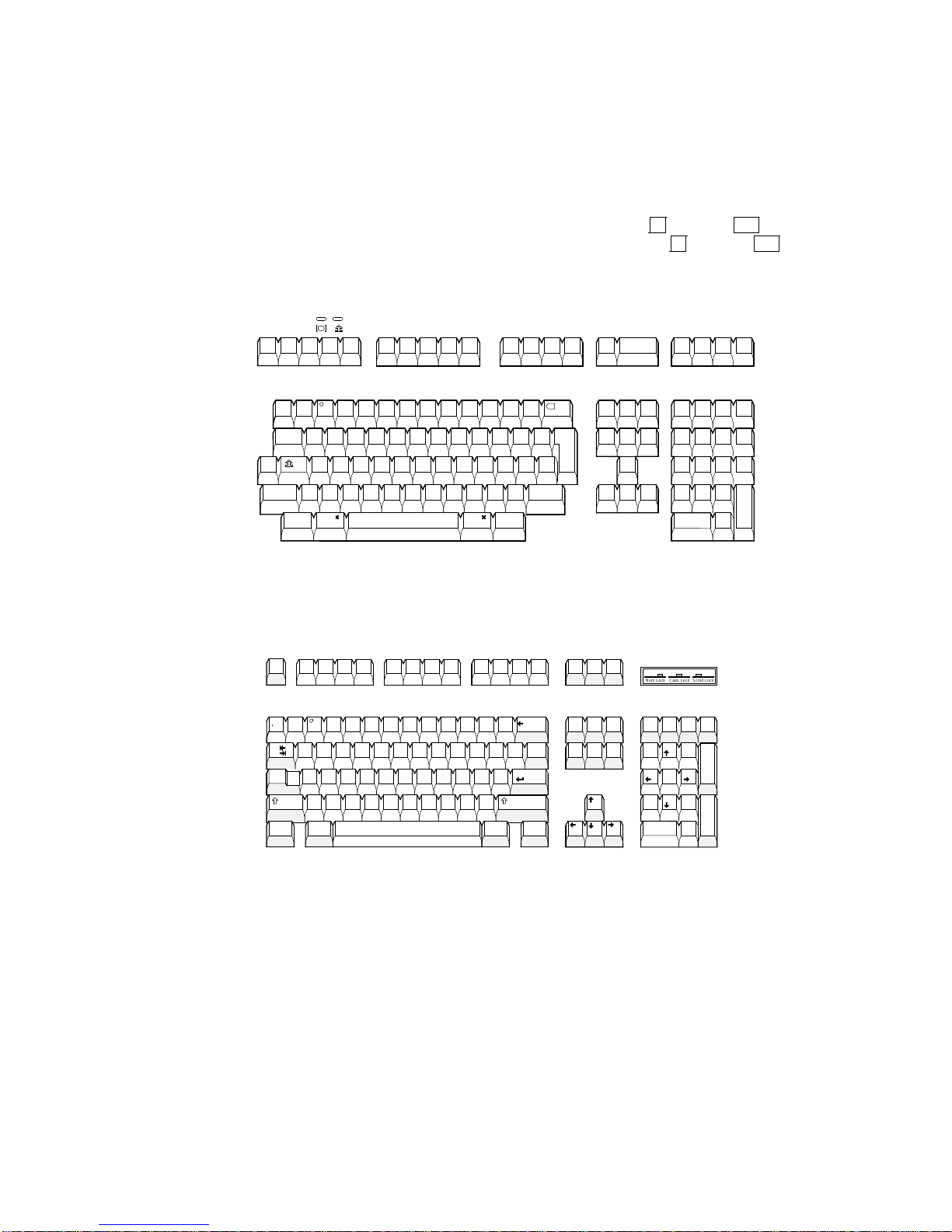
Overview
1.3 Keyboard Features
1.3 Keyboard Features
The VT520 offers a choice of two keyboard layouts—a VT keyboard layout (LK411)
or an enhanced PC keyboard layout (PCXAL). The VT keyboard (Figure 1–1) and
the PC keyboard (Figure 1–2) differ in the placement of some of the keys, like
the Control key. A VT keyboard has 20 function keys,F1through
main keypad, while a PC keyboard has 12 function keys,F1through
Figure 1–1 Sample VT Keyboard Layout
North American/United Kingdom (Word Processing Version)
F4
F2 F3
F1
F5
F20
, above the
F12
.
F8 F9
F6
F7
F10
F13
F11
F12
Help
F14
F17
F19
F20
Do
F18
a
!
#
~
(ESC)
1 2 3 4 5 6 7 8 9 0
Tab
Q
Ctrl
Shift
A S D F G H J K L
>
<
Compose
Character
$ %
^
Z X C V B N
Alt
Function
( )
Alt
Function
-
+
-
=
}
}
]
]
|
:
"
;
\
’
Shift
>
?
<
.
,
/
Compose
Character
&
*
I O PT Y UW E R
M
Figure 1–2 Sample PC Keyboard Layout
*
I O PT Y UW E R
M
North American
F8 F9 F10
_
( )
-
:
;
>
?
<
.
,
/
F11 F12
+
BackSpace
=
}
}
|
]
]
\
Enter
"
’
Shift
Altl
g
d i i
t a l
Esc
!
~
1 2 3 4 5 6 7 8 9 0
Tab
Caps
Lock
Shift
Ctrl Ctrl
F3
F2
F1
a
#
$ %
F4 F5 F6 F7
&
^
Q
A S D F G H J K L
Z X C V B N
Alt
X
Return
Find
Select
Print
Scroll
Screen
Lock
SetUp Break
EndDelete
Pause
PageUpHomeInsert
Page
Down
Insert
Here
Prev Next
PF1 PF2 PF3
Remove
7 8 9
0
Caps Lock
Num Lock
/
Num
*
Lock
7 8 9
Home PgUp
4
6
5
32
1
PgDn
End
.
0
Ins Del
GSF-MK2510-29-DG
54
6
321
.
MA-1520a-92.PS
Scroll Lock
_
+
Enter
PF4
_
,
Enter
1–2 Overview
LJ-00226a-TI0.PS
Page 29

The keyboard has the following features:
• An IBM PS/2-compatible 6-pin mini DIN connector.
• Keyboard keys that can be reprogrammed to send single characters, to send
character sequences, or to invoke local functions (Hold, Copy and Paste,
Remove, Insert, Print Page, Toggle Autoprint, Set-Up, Break, and so on).
• A local user-defined key editor. Key definitions can be saved in nonvolatile
memory.
• Eight levels of user-defined function keys using any combination of Shift,
Control, and Alt.
• 971 bytes of nonvolatile memory available for custom user-defined keys
(UDKs)/Session, which cannot be reallocated. The maximum length for a
UDK definition is 255 bytes.
1.4 Printer Port Features
The terminal has the following printer port features:
• A Centronics parallel printer port.
Overview
1.3 Keyboard Features
• IBM ProPrinter support.
• Bidirectional serial communication ports.
• Baud rates from 300 to 115.2K baud.
• Null characters that can pass as data to the printer port.
1.5 Display and Text Capabilities
The terminal has both ANSI and ASCII display and text processing capabilities.
The features of each are listed below.
1.5.1 ANSI
• Macro capability
• Display: 26, 42, or 53 data lines
• Selectable page size: 24, 25, 36, 42, 48, 50, or 72 lines
• Full status line (occupies one data line)
• Separate keyboard indicator line
• Three pages of 24 lines
• SCO Console mode
1.5.2 ASCII
• Terminal emulations:
WYSE: 325 (color model only), 50, 50+, 60 native, 160 text only, 120, 150,
PCTerm
Televideo: TVI 950, 925, 910+
Applied Digital Data Systems: ADDS A2
• Dim and invisible character attributes
Overview 1–3
Page 30

Overview
1.6 Enhanced Set-Up
1.6 Enhanced Set-Up
The terminal provides an enhanced menu-based Set-Up, allowing common
features to be accessed easily from a single screen. All Set-Up features are host
controllable to allow remote configuration. The terminal also has a means to lock
out the local setup key.
Set-Up menus are available in English, French, German, Italian, or Spanish. For
details, see Chapter 2, Set-Up.
1.7 Desktop Productivity Features
The terminal has the following desktop productivity features:
• Local copy and paste (not available in PCTerm mode)
• Time of day clock (host or locally set, no battery back up)
• Desktop calculator with decimal, octal, and hex conversions
• Display character set tables.
• Review previous data lines.
For details, see Chapter 3, Desktop Features.
1.8 Character Set Support
In addition to the traditional Digital graphic character sets (DEC Multinational,
NRCS, and so on), the VT520 supports Cyrillic, Greek, Hebrew, Turkish, most
Eastern European languages, and PC character sets. For details, see Chapter 7,
Character Sets.
1.9 Ergonomics (Human Factors) Features
The terminal is designed to provide a high-quality human interface and longterm reliability at low cost. The VT520 offers 72 Hz refresh, full overscan. The
terminal has the following features:
• 35.5 cm (14 in) flat face, antiglare CRT screen
2
• Improved resolution of 802
432 with overscan.)
• 72 Hz refresh
• Overscan
• Additional fonts (see Table 1–1)
• Tilt/swivel base
• Choice of keyboards
• Accessibility aids
1
480 pixels. (The mono VT520 also has 800
2
1
Not available in color model.
1–4 Overview
Page 31

Table 1–1 VT520/25 Font Sizes
80 Columns 132 Columns Maximum Number of Lines
10216 6216 26 lines + keyboard indicator line
10210 6210 42 lines + keyboard indicator line
10
2
8 628 53 lines + keyboard indicator line
1.10 Field-Upgradable Firmware
All VT520 models include support for a 4 Mbit (512 KByte) ROM cartridge option.
The base unit comes with a factory-installed ROM. The ROM cartridge connector
is protected by a ROM cartridge cover. To install new code, the ROM cartridge
cover is removed, and a ROM cartridge with attached cover is plugged into the
ROM connector. The new code completely supersedes the factory-installed ROM
code. It does not overlay or extend the factory code.
If you service the terminal with a ROM cartridge installed, turn the
power Off, and remove and save the ROM cartridge to put it on the new
terminal.
Overview
1.9 Ergonomics (Human Factors) Features
Note
To install a ROM cartridge with new firmware, use the following steps:
1. Turn the power off before installing the ROM cartridge.
2. Turn the power on and press
3. Select Actions.Restore factory defaults and press
4. Select Sessions.Save all sessions and press
F3
.
Return
.
Return
.
The installation is now complete. When you power-on the terminal, the message
‘‘ROM card active’’ is displayed in the upper-left corner of the display. Note that
steps 3 and 4 are necessary to initialize the terminal’s non-volatile memory for
use with the ROM cartridge firmware. Failure to perform these steps may cause
the terminal to report an NVR error.
Overview 1–5
Page 32

Overview
1.11 Comparison with previous VT Terminals
1.11 Comparison with previous VT Terminals
The VT520 is functionally compatible with other ANSI products with the
following exceptions:
• Terminal ID
The Primary Device Attributes can report additional extensions to cover
new features. See Chapter 4 for a summary of the control functions. The
Secondary Device Attributes are different.
VT520 CSI > 64 ; Pv ; 0 c
VT525 CSI > 65 ; Pv ; 0 c
Where Pv is the firmware version number.
• Dynamically Redefinable Character Set (DRCS) Fonts
The VT520 has four buffers, which can load up to two dynamically redefinable
character sets, each with an 80-column font and a 132-column font.
• Keyboards
VT420 keyboards cannot be used on the VT520; however, the VT520 can
emulate the VT420 keyboard behavior when configured accordingly.
• Four Sessions
The VT520 is a multi-session terminal. You can have up to four
sessions enabled. More than one session can be established on the same
communication port.
• PC Character Sets
PC character sets are available in PC Term and SCO Console mode only.
1–6 Overview
Page 33

This chapter describes VT520 Set-Up features. Set-Up is used to examine or
Enter,Return,Do
, or
Select
invokes the action or
setting for the current menu item.
The Set-Up function may be reassigned to other key combinations or can be
disabled it for local entry into Set-Up. When you pressF3as the first key
after the terminal is powered on, you always enter Set-Up, regardless of which
keyboard you use or howF3is defined.
Set-Up 2–1
change terminal operating features, such as transmit/receive speeds, type of
cursor, or key definitions.
2.1 Entering Set-Up
You enter Set-Up by pressing the key designated as the Set-Up key. Pressing this
key alternately places the terminal in Set-Up mode or returns it to the operating
mode.
On a . . . The Set-Up key is . . .
2
Set-Up
VT keyboard
SCO Console mode
PC keyboard
Figure 2–1 Set-Up
MA049193.GRA
The Set-Up display consists of pull-right menus. You can move back and forth
with the arrow keys. Pressing
F3
on the top row.
Caps Lock F3
Caps Lock Print Screen
Alt Print Screen
or
.
Page 34

Set-Up
) in lists and in
boldface in text.
2–2 Set-Up
2.1 Entering Set-Up
2.1.1 Effects of Entering Set-Up
Placing the terminal in Set-Up mode causes no loss of data if a Flow Control
protocol is in use on the communications port. The first Set-Up menu is displayed
on the screen. Upon exiting Set-Up, the previous text is restored.
Entering Set-Up has the following side effects:
• Any compose sequence in progress is aborted and the keyboard is unlocked.
• A Set-Up Summary Line is displayed.
• Press
• Printer operations are suspended and are resumed upon exiting Set-Up.
Shift
2.1.2 Set-Up Languages
The VT520 Set-Up menus can be displayed in five languages using a Set-Up
feature. A menu allows you to choose the language in which all subsequent
Set-Up menus and displays are written. Selections from this Set-Up language
menu (Figure 2–2) take effect immediately. This feature can also be invoked by
DECSSL.
Figure 2–2 Set-Up Language Selection
to show the Indicator Status Line.
2.1.3 Power-On Settings and Defaults
The VT520 terminal stores many of its feature settings in nonvolatile memory
(NVM). Nonvolatile memory retains these settings even when power is shut
off. In addition to storing operator-selected features, the terminal retains the
factory default settings in permanent memory. By using Set-Up, you can modify
individual terminal features, recall the feature settings stored in nonvolatile
memory, or recall the factory default settings.
In this chapter, the defaults are shown with a solid bullet (
Page 35

2.1.4 Self-test Error Messages
At power-up, the VT520 terminal executes a series of self-tests, displays a
message indicating whether the self-tests were successful, and displays a banner
message. (To change the banner message, see Section 2.4.6.)
If the self-tests detect an error, one of the following messages is displayed on the
terminal in place of "Selftest OK."
Table 2–1 Error Messages
Message Meaning
Set-Up
2.1 Entering Set-Up
NVR Error - 1 A firmware update, or loss of power while
RS-232 Port Data Error - 2 Communications problem inside terminal.
RS-232 Port Controls Error - 3 Communications problem inside terminal.
DEC-423 Port Error - 5 Communications problem inside terminal.
Parallel Port Error - 6 Communications problem inside terminal.
ROM Cartridge Error - 7 Turn the terminal off, and make sure the ROM
Keyboard Error - 8 Turn the terminal off, and make sure the
writing to the NVR during a Save settings
process may cause this error. Try Actions
Recall factory defaults followed by Session
Save settings for all .
Call for service.
Call for service.
Call for service.
Call for service.
cartridge is seated firmly on its connector pins.
Turn the terminal on. If the problem continues,
try another ROM cartridge. If the new ROM
cartridge does not work, the problem is inside
the terminal; in which case, call for service.
keyboard cable is plugged in. Turn the terminal
on. If the problem continues, try another
keyboard. If the new keyboard does not work,
the problem is inside the terminal; in which
case, call for service.
.
.
2.1.5 Context Sensitivity
On the screen, a check box=or radio button () indicates the current user
selection and normally reflects the operating state of the terminal.
Certain feature selections overlap and could contradict each other, so they cannot
be active at the same time. These are called context sensitive features, which are
displayed with the dim video attribute in Set-Up. Example:
You cannot select Comm3 as a printer port if it is selected as a
communications port.
Table 2–2 lists the set-up features that are context sensitive.
Set-Up 2–3
Page 36

Set-Up
2.1 Entering Set-Up
Table 2–2 Context Sensitive Set-Up Features
Menu Item Dimmed when . . .
Session
Display
Color
Terminal type
ASCII emulation
Keyboard
Communication
Modem
Printer
.
.
.
.
.
.
.
Pages per session Page
memory allocation
Lines per screen
Lines per page
Cursor direction Keyboard language is not Hebrew.
Energy saver CRT saver = never is selected.
Overscan Terminal is a color terminal.
ASCII color mode, Reverse
and blank attributes, and
Intensity attributes
Alternate text colors... Select color mode is other than Alternate color.
Select color mode Terminal type
Terminal ID to host Terminal type.Emulation mode is other than a
=
7-bit NRCS characters Emulation mode is set to VT100/VT52; or
.
TVI page-flip Terminal type
Key encoding
Character, Scan code and
Key position
Data processing keys A PC keyboard is connected.
Map PC keyboard to VT The keyboard is not a PC keyboard.
.
Port select Comm3 Comm3 is selected as a communications port. (It
Half duplex The host Communication
Transmit flow control
DSR and Both
Receive flow control
DTR and Both
Disconnect delay and
Modem speed
Serial print speed,
2-way communication,
Transmit flow control,
Receive flow control, Word
size, Parity, and Stop bits
DEC/ISO char sets IBM ProPrinter is selected.
PC character sets DEC ANSI printer is selected.
Print mode
.
.
.
.
Controller Display.Show control characters is selected.
Page selection exceed the number of unassigned
pages available.
Sizes are not available based on the current page
memory allocation.
WYSE is selected; use ASCII emulation
lines and Pages.
Emulation mode is set to other than an ASCII
terminal emulation.
.
VT or SCO console.
VT or SCO console.
Communication
8-bit NRC set exists for the keyboard language.
Terminal type.Emulation mode is set to VT or
SCO console.
TVI.
ASCII emulation is selected, or a PC keyboard is
connected.
can be either a comm port or a printer port but not
both.)
S1=comm2.
The Modem
The Modem
The Modem.Enable modem control is not
selected.
The Communication
the Print = parallel selections.
Emulation mode is other than a
.
Word size is 7-bits; or no
.
Emulation mode is other than
.
Port select is set to
.
Enable modem control is selected.
.
Enable modem control is selected.
.
Port select is set to one of
.
Data
2–4 Set-Up
Page 37

2.1.6 Set-Up Summary Line
1
2
3
4
5
6
Item Information Displayed Communication Feature
!
S1=comm1 Port selected: comm1, comm2, or comm3
"
9600 Transmit speed: 9600 baud
N Parity: N=none, E=even, O=odd, M=mark,
S=space
8 Word size: 7 or 8 bits
1 Stop bits: 1 or 2 bits
#
ISO Latin-1 Default character set or
PC set in PCTerm mode
$
North American Keyboard language
%
VT520 Emulation mode
&
V2.1 Firmware version
The summary line is visible whenever the terminal is in Set-Up, except under the
following conditions:
• You press a
Shift
key. Pressing either
Shift
key causes the normal Indicator
Status Line to replace the Set-Up Summary Line.
• The Set-Up Summary line is temporarily replaced by an error or status
message from the terminal. In this case, the error or status message is shown
in place of the Set-Up Summary line until you type another key.
The Set-Up Summary Line appears in the currently selected set-up language.
2.1.7 Set-Up Status Messages
The Status or Set-Up Summary line is sometimes replaced by a Set-Up status
message until the next user keystroke. Set-Up status messages are displayed
whenever the effect of a set-up action would not otherwise be apparent. Example:
"Done" is displayed after the Reset terminal action has completed.
The following are set-up status messages:
• Done
• NVR Error
• Incompatible settings not restored - check pages per session and lines per
page
Set-Up 2–5
The Set-Up Summary Line (Figure 2–3) shows the important set-up features that
affect whether the terminal can successfully communicate with the host. If the
terminal is not working, the Set-Up Summary Line allows you to quickly verify if
the communication features are set appropriately. The summary line is displayed
below the last data line, where the status line would normally appear.
Figure 2–3 Set-Up Summary Line
11
The Set-Up Summary Line contains the following set-up information extracted
from the Set-Up displays.
Set-Up
2.1 Entering Set-Up
Page 38

Set-Up
2.1 Entering Set-Up
• Incompatible settings not restored - check comm port selection
• Page memory reallocated
• Sessions not enabled - No Session Management response from host
• Session # terminated abnormally
• Insufficient terminal resources to open Session
• Sessions not enabled - Unable to run with host Session Management version
• Session open request pending
• Session opened
• No response from host for Session Management
• Data overrun occurred on Session #
• Sessions not enabled - Sessions not selected
• Session # terminated normally
• Insufficient host resources to open Session
• Sessions disabled
• Sessions enabled - Restoring previous sessions
Set-Up functions that require additional time to process display the message
‘‘Please wait’’ until they have completed. Save settings for all and Restore
settings for all display this message.
2.1.8 Status Line
The VT520 terminal has a status display with the following features:
• The clock time appears on the status display if the local clock has been
initialized since the terminal was last powered on.
• In the ASCII emulation modes, the host-writable status line becomes the
WYSE Editing status line.
• When enabled, the Accessibility Aids feature ("sticky keys") displays icons in
the Keyboard Indicator line. For details, see Section 8.11.2.
The VT520 Indicator status line includes the Active Position Indicator, Printer
Status Indicator, Modem Status Indicator, and local clock time in the desired
format. Example:
1(24,008) Printer: None Modem: DSR 3:15 PM
2.1.9 Keyboard Indicator Line
The Keyboard Indicator Line has the following features:
• It is displayed in the Set-Up language.
• It has active keyboard layout. Nothing is displayed for Group 1. "G2" is
displayed for Group 2, along with a small icon representing the right side of
the top of the keycap. (To see this icon, press
2, press
• For Greek, Hebrew, and Russian, "G2" is replaced by "Grk", "Heb", and "Rus",
respectively.
2–6 Set-Up
Ctrl/Alt/F1
Ctrl/Alt/F2
.)
. To return from Group
Page 39

• Visible bell—This feature flashes a bell ringing font whenever a sound is
+
moves the cursor to the next item in the main menu. Pressing
)
moves the cursor right to the first item of the submenu, making it the active
menu.
Set-Up 2–7
generated.
• When the Num Lock state is active on an EPC keyboard, "Num Lock" is
displayed.
• When an EPC keyboard is operating in VT style, "VT" is displayed in place of
the Num Lock indicator.
• In French and Spanish, an icon replaces the word "Lock" on the indicator line.
Example:
Heb Num Lock Copy Hold Lock Compose Wait
2.2 Set-Up Screen Text
The main menu, shown in Figure 2–4, is the first menu displayed whenever you
enter Set-Up. As the first menu, it holds the main directory of Set-Up features
and those features which are commonly accessed and must be easy to find at all
times. The Actions submenu is also displayed, since the Actions menu item is
currently selected.
Unless stated otherwise, the following general descriptions apply:
Set-Up
2.1 Entering Set-Up
• Changes to feature settings do not take effect until you exit Set-Up. Only net
changes have an effect—a change to a new value and back to an old value has
no effect.
• The setting choices for some features are shown in the corresponding Set-Up
displays. Where all the choices could not be displayed, additional choices are
listed immediately under the figure.
Figure 2–4 Main and Terminal Actions Menu
MA049193.GRA
Pressing
Page 40

Set-Up
2.3 Main Menu
2.3 Main Menu
The following descriptions refer to Figure 2–4.
The items above the dividing line in the main menu form a directory to the major
functional areas of set-up features. Each item has a corresponding submenu or
dialog box.
Pressing the Set-Up key from within a dialog box will flash the OK button as if it
were pressed and accept the corresponding changes before exiting Set-Up.
Below the dividing line are features that need to be easy to find from any menu.
2.3.1 On-Line
The On-line feature allows you to select whether the terminal directs keyboard
input to its host port UART to communicate with a remote host (On-Line), or
directs keyboard input directly to the screen (receive character parser) without
sending to a remote host (off-line or local).
The On-line selection is different from the Local echo mode in the
Communications Set-Up submenu. When On-line is disabled (local
mode), nothing is sent to the host. Any keyboard input is directed to the
receive character parser, which updates the screen.
In contrast, Local echo causes characters sent to the host port to also
be directed back to the receive character parser, as if they had been
received (echoed) from the host. Local echo is temporarily disabled when
the terminal is in either Local mode or Local Controller mode, because
keyboard input is already being redirected to the screen or printer port.
If an NVR error occurs during power-up, the terminal switches to Local
mode.
Note
2–8 Set-Up
Terminal reports, such as Answerback, DA, CPR, DECTSR, DECRPM, DECRPSS,
DECAUPSS, DECCIR, DECTABSR and DSR, are not directed to the display.
While in "local", host communications are put on "hold": All data received is
buffered. If necessary, an XOFF is sent (or DTR is deasserted) to prevent buffer
overflow. This buffered data is directed to the display when On-line mode is
reentered. Note that the received character buffer (silo) is responsible for sending
XON and XOFF when needed, not the On-line/Local state.
When in Local mode, modem signals, including DTR, are unaffected. No
disconnect is performed. The functions of the printer port remain unchanged
in Local mode. They function the same as in On-line mode.
When in Local mode and Printer To Host mode is selected, data from the printer
port is displayed on the video terminal.
When both Local mode and Printer Controller mode are selected, the terminal
is in Local Controller mode. Keyboard characters are sent to the printer port.
Note that in "regular local" mode, any keyboard output is directed to the screen,
but in "regular controller" mode, the keyboard output is directed at the host
port. When Local Controller mode is exited to Local mode, the terminal redirects
keyboard output from the printer to the screen (and parser). When you change
from Local Controller mode to Printer Controller mode, the terminal transmits
the characters accumulated in the receive silo to the printer.
Page 41

2.3.2 Save Settings
The Save settings menu item, when invoked by pressing
causes the settings for most Set-Up controlled operating features to be saved in
nonvolatile memory, where they become the power-on settings.
The following settings are not saved.
• Keyboard encoding mode
• Application cursor keys when set by a host control function.
• Application keypad mode when set by a host control function.
2.3.3 Restore Settings
Restore settings is an action field that is used to replace all saved Set-Up
parameters with the values stored in the NVR. As a side effect, this feature
performs a disconnect sequence, clears the screen, reinitializes the user-definable
keys (as saved), clears the soft character set, returns the cursor to the upper
left corner, aborts any print operation in progress, aborts ESC, CSI, and DCS
sequences (and control strings), and shows "Done" on the status line. This action
can also be invoked by the RIS control function.
2.3.4 Exit Set-Up
The Exit Set-Up menu item, when invoked by pressing
to exit Set-Up. The effect is identical to pressing the Set-Up key while in Set-Up.
2.3 Main Menu
Return
Enter
, causes the terminal
or
Enter
Set-Up
,
2.4 Actions Menu
The following descriptions refer to Figure 2–4. Certain Set-Up features instruct
the terminal to perform an immediate action when they are invoked. These
features are grouped in the terminal Actions menu.
2.4.1 Clear Display
The Clear display feature clears the active page (including the lines which have
temporarily disappeared while the you are in Set-Up).
2.4.2 Clear Communications
This feature is used to clear communication buffers and flags. It does not affect
the On-Line/Local state. It is not invoked by any control functions.
Clear communications:
• Aborts any print operation in progress
• Aborts any escape sequence, control sequence, control string, or character
string processing (ESC, CSI, DCS, APC, OSC, PM, SOS)
• Clears the keyboard buffers
• Clears the receive silo
• Clears the transmit silo
• Takes the terminal out of Printer Controller mode
• Sends XON on to the host port
• Sends XON to the printer port if Printer To Host and XOFF are enabled
Set-Up 2–9
Page 42

Set-Up
2.4 Actions Menu
• Resets XOFF received flags on both ports
• Does not clear the screen
• Clears KAM locked condition
• Clears the "printer port has seen DSR since power up" flag. When in Set-Up,
Ctrl Enter
disables sessions and clears TD/SMP.
2.4.3 Reset this Session
The Reset this session menu selection only resets the active session.
To . . . Press . . .
Reset all four sessions,
Perform a power-up reset,
The Reset this session Set-Up feature resets the terminal to a "known state."
This function is like Soft Terminal Reset (DECSTR), except DECSTR resets the
Character Set mode to "8-bit Characters" and Reset terminal does not.
Additions:
• Keyboard encoding is reset to "character."
• PCTerm mode is not selected.
From Set-Up, a soft reset using Reset terminal always works regardless
of the terminal mode; but using mode changing control functions
(DECSCL, S8C1T, S7C1T, DECANM), the soft reset is sometimes not
performed.
2.4.4 Restore Factory Defaults
The Restore factory defaults menu selection restores the factory default
settings for all four sessions. There is no provision to restore factory defaults
to a single session. Restore settings on the main menu only restores the active
session’s settings from NVM.
Control
Control Set-Up
Reset this session.
Note
from within Set-Up.
As a side effect, Restore factory defaults does the following:
• Performs a disconnect sequence
• Clears the screen
• Reinitializes the user-definable keys
• Clears the soft font
• Returns the cursor to upper-left corner
• Aborts print operations in progress
• Aborts ESC, CSI and DCS sequences
• Displays the "Done" message on the status line
2–10 Set-Up
Page 43

2.4.5 Clock, Calculator, Show Character Sets
The Clock, Calculator, and Show character sets menu items are used to
invoke the corresponding desktop productivity features. Refer to Chapter 3.
2.4.6 Banner Message
The Banner message menu item invokes a dialog box with a 30-character limit.
When this feature is selected, a dialog box is displayed with a reverse video text
entry area 30 characters long. If a Banner message is currently defined, the
message is displayed in the text entry area. The
used to delete backwards and enter a new Banner message.
All characters that can be generated by the keyboard are legal in this field
(including primary and secondary keyboard language characters). As such, no
errors are reported, except when trying to enter more than 30 characters. In this
case, the bell rings (if enabled), and no more characters are accepted. The factory
default message is no message at all (a blank field).
From the Actions menu, select Banner message....
<
Set-Up
2.4 Actions Menu
x
Delete
or
key can then be
1. Press
Return
2. Enter your banner message.
3. Press the
4. Press
Return
5. Use the Save settings menu item to save the Banner message.
2.5 Multiple Sessions
Multiple sessions extends the VT520 to act like four terminals in one. A session
is an active connection between the terminal and a host system. The Session
Set-Up menu controls the use of more than one session. See Figure 2–18.
The VT520 supports up to four sessions using virtual terminals. Each virtual
terminal maintains the full keyboard and display state of a real physical terminal
but shares a single keyboard and display with other virtual terminals. Before you
can login using a virtual terminal, it must be connected to a host computer.
VT520 session virtual terminals can be connected directly to a host computer
through any of the three serial communication ports on the back of the terminal.
Since there are only three comm ports, this method alone can only support three
sessions.
To use a fourth session or reduce the number of serial comm lines needed, more
than one session must be connected through a single comm port. The VT520
allows this using a session management protocol, called TD/SMP (Terminal
Device/Session Management Protocol). TD/SMP allows two or more sessions to
share a single comm line, as long as the other end of the comm line supports the
protocol. To enable TD/SMP at the terminal, you simply assign more than one
session virtual terminal to the same comm port in Set-Up.
or
+
to select
or
Enter
to display a dialog box.
OK
button.
Enter
to return to the Set-Up menu.
TD/SMP is standard on most terminal servers. If you are using a terminal server,
check with its documentation to determine if it can run TD/SMP.
Set-Up 2–11
Page 44

Set-Up
2.5 Multiple Sessions
2.5.1 Enabling and Controlling the Session Configuration
The VT520 provides three serial communication ports which may be assigned to
session virtual terminals in any combination. When only one virtual terminal
is assigned to a communications port, the terminal functions as a single session
terminal. The other three session selections are dimmed. The single session may
be allocated 8 pages of 25 lines each by 80 or 132 columns. The color terminal
supports 9 pages.
As session virtual terminals are assigned to physical communication ports,
the terminal’s firmware allocates the necessary structures to create the virtual
terminals up to a maximum of four. When more than one virtual terminal
is assigned to a single communication port, the Terminal Device/Session
Management Protocol (TD/SMP) is used.
2.5.2 Multiple Sessions using a Terminal Server with TD/SMP
Procedure:
1. At the
Local> set port multi enable
Local>
prompt, enter the following command:
Return
2. Continue with your login procedure.
To permanently set a terminal server port to use TD/SMP, you would type:
Local> define port multi enable
Return
2.5.3 Multiple Sessions using SSU Host Software
If your VT520 is connected directly to a host computer without a terminal server,
use can still use TD/SMP by running the Session Support Utility (SSU) on your
host computer. On a system that has SSU software, such as OSF or OpenVMS,
open the first session as follows:
$ mcr ssu
Return
On an UNIX-style system, open the first using:
% ssu
2.5.4 Opening Another Session
Once TD/SMP is enabled, you can open a new session and switch between them
as follows:
1. Press theF4(Session) key on a VT keyboard; or press
numeric keypad on a PC keyboard.
F4 is used as the Session key on the VT keyboard (factory default). For
consistency,
On Enhanced PC layout keyboards (PC style),
Caps Lock Scroll Lock
or
substituted for the VT Session key (F4) anywhere it is used.
Caps Lock F4
also works on the VT keyboard.
are used as the Session keystroke and may be
Caps Lock 0
Caps Lock F4
on the
2. To go directly to a particular session, press
numeric keypad.
The currently selected session is indicated on the Set-Up Summary line along
with its corresponding communications port assignment (S1=comm1 for example).
2–12 Set-Up
Caps Lock 1,2,3
or4on the
Page 45

2.5.5 Restoring an Interrupted Session
When a session is interrupted, the VT520 or the host system may lose the context
of the current session. After the terminal and system regain communication, you
can restore the context of the interrupted session without canceling the session
and starting over again.
Set-Up
2.5 Multiple Sessions
To restore a session, press theF4key; or press
keypad. Or you can enter Set-Up Communications.Port Select and assign
the session to a comm port.
2.5.6 Session Management
Assigning more than one session virtual terminal to a single comm port
automatically allows session management.
Reducing the number of session virtual terminals assigned to a single comm port
from two to one automatically disables session management if it was enabled.
When Display
for each session up to 30 characters for the window title. The first 12 characters
become the default icon name, which you can change in Set-Up.
.
2.6 Session Menu
The Session Set-Up (Figure 2–5) controls the use of the more than one session.
Figure 2–5 Session Menu
Caps Lock 0
Framed windows is selected in Set-Up, you can assign a name
on the numeric
On a VT keyboard,F4is used as the Session key (factory default). On a
PC keyboard,
substituted in this text for VT Session key (F4) anywhere it is used. For
consistency,
CapsLock 0
CapsLock 0
kpd is used as the Session keystroke and may be
kpd also works on the VT keyboard.
Set-Up 2–13
Page 46

Set-Up
2.6 Session Menu
2.6.1 Select Session
The Select session submenu is used to select the active session. All SetUp selections apply to the currently active session. Most settings are kept
independently for each session and may be saved in non-volatile memory.
Exceptions are made for settings that control the physical hardware that is
shared between sessions. Example:
A single communications port cannot be used for both a session connection
and a printer port simultaneously.
The terminal ensures that conflicts like this do not happen by disabling
(displaying as dim) or resetting certain selections. All such exceptions are
noted explicitly.
A disabled session has its session selection dimmed but can still be configured in
Set-Up if it was active when Set-Up was entered. At least one session is always
enabled. If the currently active session is disabled, the previous enabled session
becomes the active session when you exit Set-Up.
While the terminal is in Set-Up, the Session key can be used to cycle between
sessions in order. You can also use
select enabled sessions explicitly. The currently selected session is indicated on
the Set-Up Summary line along with its corresponding communications port
assignment (S1=comm1 for example).
CapsLock 1
kpd through
CapsLock 4
kpd to
Selecting a different session within Set-Up does not affect the active session at
the host until you exit Set-Up.
2.6.2 Session Name
The Enter session name dialog box allows a 30 character descriptive name to be
entered for the active session. Depending on the windowing option selected, this
name is displayed with the corresponding session window to help you identify
each session. See also Section 2.8.19.
Entering a session name is similar to entering an answerback message. A session
name is not saved automatically; you must use the Save settings menu item.
Icon name — The first 12 characters of the session name is used as the icon
name, but this name may be overwritten if a separate icon name is specified
by a host control function. The session name is included as the "application_
parameter" in the TD/SMP OPEN_SESSION command and may be used to select
a desired service.
2.6.3 Pages per Session
The Pages per session dialog box displays a Session Page Memory Allocation
screen (Figure 2–6), which allows you to control how the terminal’s page memory
is allocated among the enabled sessions. The VT520 provides 8 pages of 25 lines
by 80 or 132 columns as standard (9 pages on the color terminal). A disabled
session (Comm = session off) is dimmed and does not use any page memory.
Page selections which are not available in the current configuration are dimmed
and cannot be selected. Thus, you may have to decrease the number of pages
assigned to one session before you can increase the number of pages assigned to
another. Any data on these pages is erased.
2–14 Set-Up
Page 47

Figure 2–6 Session Page Memory Allocation
Set-Up
2.6 Session Menu
The ‘‘__pages’’ selections in Figure 2–6 allow you to enter a number of pages
not shown as one of the other choices. The number in parenthesis below these
selections is maximum number of pages available to each session. When you
select this radio button, this maximum number is used as the number of pages
for this session unless you enter a new value. Pressing Enter selects the radio
button and maximum number of pages in a single operation. Alternatively, any
number up to the maximum number of pages available can be typed in directly.
The maximum number of pages available to each session change as the allocation
to other sessions changes. If only one session is enabled, the maximum number
of pages in a standard VT520 is 8.
A session that is currently disabled (Comm = session off) is dimmed and shows
Max pages as zero to remind you that it is not using any page memory. (Zero
is the factory default for S3 and S4.) A disabled session can be re-enabled at
any time by assigning it to a communications port. When a disabled session
is re-enabled, its initial page memory allocation is the previous allocation for
that session if available from the free resource pool; otherwise, it is one page
of 25 lines. If all pages are currently assigned, the terminal reduces by one
the allocation to the highest numbered session with more than one page. This
automatic adjustment of page allocation ensures that you can always enable
another session without worrying about memory management. If a session
requires a fixed number of pages for compatibility, you can assign that number
to S1 and S2. We recommend that you allocate page memory for the number of
sessions to be used ahead of time to avoid losing data in an existing session when
creating a new one.
Set-Up 2–15
Page 48

Set-Up
2.6 Session Menu
In case you cause the terminal to re-assign page memory while sessions are in
use, the pages assigned to a new session is first erased. If the cursor was on that
page, it goes to page one. The terminal issues a warning message to indicate
what may have changed for you to check, such as:
"Page memory reallocated, check
pages per session and lines per
page."
"Incompatible settings not
restored, check pages per session
and lines per page."
The terminal created a new session forcing
page memory to be re-allocated.
The terminal is unable to copy or restore a
requested setting.
2.6.4 Soft Character Sets/Session
The Soft char sets/session submenu allows you to specify the allocation of
DRCS character set buffers to multiple sessions on the VT520 mono terminal
only.
• Two each S1 and S2 allocates two character set buffers each to S1 and S2
making S1 and S2 compatible with terminals, like the VT510, VGB10, or
WS510 video terminals. In this case, S3 and S4 do not support the DRCS
extension, which is reported in their primary device attributes response.
• One each gives each session a single DRCS character set buffer making each
session compatible with terminals, like the VT420.
This submenu is not included in the color terminal since it has enough memory to
give all four sessions Two each.
2.6.5 Save Settings for All and Restore Settings for All
The Save settings for all and Restore settings for all menu items are like
the Save settings and Restore settings items in the main menu except that they
operate on all four sessions at once.
Since restoring settings for four sessions can take some time, the screen is cleared
and a "Please wait" message is displayed in the center of the screen for one
second to begin the restore operation. A "Done" or "Incompatible setting not
restored" message is displayed upon completion.
When restoring settings saved in non-volatile memory, it is possible that the
number of pages saved for a session is larger than the number of pages available
in the free resource pool. In this case, the same approach is used as when a
session is newly enabled. The process can be summarized as follows:
1. When restoring settings for more than one session, settings for each session
are restored in order (S1, S2, S3, S4).
2. The saved page memory allocation is restored if that number of pages is
available from the free resource pool, otherwise the page memory allocation is
set to one page of 25 lines.
3. If no pages are available from the free resource pool, the terminal reduces by
one the allocation to the highest numbered session with more than one page.
4. If a previously saved setting is not restored, the terminal displays the
information message "Incompatible setting not restored, check pages per
session and lines per page" on the error line. The message is cleared on the
next keystroke.
2–16 Set-Up
Page 49

The principle used is to restore all the settings possible, replace those individual
settings that can’t be restored with some reasonable default, and display the
information message "Incompatible setting not restored..." if necessary. This same
principle is used in all cases where settings cannot be copied or restored due to
resource limitations or conflicts with other settings.
The active session number is not saved in NVM. Restore settings for all does not
change the active session.
2.6.6 Copy Settings from Menu
The Copy settings from menu allows you to copy settings from another session
to the current one. The currently active or in-use settings are copied so it is not
necessary to save settings in one session before copying them to another.
The communications port selection and print port selection are not copied. The
VT520 conceptual model is four terminals sitting on your desk. Copying settings
from one terminal to another does not transfer the communication cables.
Copying settings to a disabled session does not automatically enable it since the
"Comm = session off" setting is not changed.
The session name if any is not copied. Since the conceptual model is four
terminals, copying settings does not copy the label on each terminal. The page
memory allocation is copied unless there are not sufficient pages available in the
free resource pool. In this case, the page memory allocation remains unchanged,
and the information message "Incompatible settings not restored, check pages per
session and lines per page" is displayed.
Set-Up
2.6 Session Menu
2.6.7 Update Session
The Update session menu controls how a session is updated when it is not the
active session.
• Only when active prevents the session from being updated unless it is the
active session.
• When available allows the page memory of this session to be updated when
the VT520 is not otherwise busy with the active session (factory default).
• At regular intervals ensures that the page memory of this session is
updated on a regular basis. Updating an inactive session at regular intervals
slows down the active session as necessary.
Increasing the number of sessions assigned to a communication port from
1 to 2 causes the terminal to send the TD/SMP ENABLE_SESSIONS
command. Conversely reducing the number of sessions from 2 to 1 sends
a TD/SMP DISABLE_SESSIONS command. Pressing Control while
selecting "Clear comm" in Set-Up also sends DISABLE_SESSIONS.
Note
Set-Up 2–17
Page 50

Set-Up
2.7 Resetting and Restoring Defaults
2.7 Resetting and Restoring Defaults
2.7.1 Reset Session
The Reset this session menu selection only resets the active session. To reset all
four sessions, press the Control key while you select Reset this session. Pressing
Control/Set- Up from within Set-Up initiates a power-up reset.
2.7.2 Restore Factory Defaults
The Restore factory defaults menu selection restores the factory default
settings for all four sessions. There is no provision to restore factory defaults
to a single session. Restore settings on the main menu only restores the active
session’s settings from NVM.
2–18 Set-Up
Page 51

2.8 Display Menu
2.8 Display Menu
Many of the features in the Display menu can be controlled by the host control
functions listed in Table 2–3. The control functions listed by function in Chapter
4 and are described fully in Chapter 5.
Table 2–3 Display Set-Up Features and Control Functions
Display Set-Up Feature Factory Default Host Control Code
Lines per screen 24, 25 or 26 DECSNLS
[ ] Auto resize DECARSM
Lines per page 24 lines x 3 pages DECSLPP
[ ] Review previous lines -
Columns per page 80 Columns DECCOLM
[/] Clear on change DECNCSM
Status display Local status DECSSDT
Scrolling mode Jump DECSCLM DECSSCLS
Screen background Dark DECSCNM
Cursor display Block DECSCUSR
[/] Blink -
[/] Enable cursor DECTCEM
Cursor coupling -
[/] Vertical coupling DECVCCM
[/] Page coupling DECPCCM
Cursor direction Left to right DECRLM
Copy direction Left to right DECRLCM
Zero 0 DECSZS
[ ] Auto wrap DECAWM
[ ] New line mode LNM
[ ] Lock user preferences [ ] Show control characters CRM
CRT saver 15 minutes DECCRTSM
[/] Host wake-up Energy saver 15 minutes DECEST
[ ] Overscan DECOSCNM (mono model
only)
[ ] Framed windows Screen alignment... DECALN
Set-Up
Set-Up 2–19
Page 52

Set-Up
2.8 Display Menu
2.8.1 Lines per Screen
This menu chooses a font that enables the selected number of lines to be viewed.
Note that you cannot view more lines than the number of lines on a page (Lines
per page).
If the Status display is enabled, it is displayed using one of the same Lines per
screen as the text for the corresponding session.
This is an operator preference feature and cannot be changed by control functions
if the operator preference is set to Lock user preferences; however, if Auto
resize is enabled at the same time, then the number of Lines per screen
changes when the page size changes.
This feature can be changed from the host using the DECSNLS control function.
Or, it may be changed indirectly from the host if Auto resize is selected and the
page configuration is changed using DECSLPP.
2.8.1.1 Auto Resize
When Auto resize is enabled, the number of lines per screen changes
automatically each time the page arrangement changes, either by the host or
through Set-Up. Table 2–4 shows how the screen size changes whenever the page
size changes when Auto Resize is set.
Table 2–4 Lines per Page vs. Lines per Screen When Auto Resize is Set
Lines per Page Lines per Screen
24 26
25 26
36 43
42 43
43 43
48 52
52 52
72 52
If Auto resize is enabled in Display Set-Up, switching to two windows will set
lines per screen to 48 and switching to one window will set lines per screen to
correspond with the most recent lines per page setting, as if DECSLPP had been
received. This applies to all sessions with auto-resize enabled.
2.8.2 Lines per Page
This menu allows you to select the page size in lines and number of pages.
The page size determines the addressing range for cursor positioning and scroll
regions. The number of lines that can be displayed depends on the current setting
of the Lines per screen feature.
Lines per page sizes not available based on the current page memory allocation
are dimmed. If the page memory allocation is changed such that the currently
selected number of lines per page is not available, the factory default page size is
used (24 lines per page for the VT emulations).
2–20 Set-Up
Page 53

When the Review previous lines feature is selected, the Lines per page
selections show the corresponding number of lines by only one page (Figure 2–7).
Figure 2–7 Lines per Page
Set-Up
2.8 Display Menu
This field is also invoked by the DECSLPP control function.
2.8.3 Review Previous Lines Buffer
The Review previous lines feature when selected re-arranges page memory
into a single page and a scroll back buffer (transcript). Lines of text scrolled up
from the first line of the page are saved in the scroll back buffer (replacing the
oldest lines saved if any). Pressing Control with the up or down arrow keys pans
the screen window up or down allowing you to view lines previously scrolled off
the top of the page up to the number of lines saved in the scroll back buffer. If
the page size is larger than the window size, pressing Control with the up arrow
key first pans to the top of the page and then pans into the scroll back buffer.
Any time lines in the scroll back buffer are available, a small down and/or up
arrow appears at the lower right position of the status line to indicate there are
additional unseen lines of the page below or above. When any text is received
from the host for this session, the screen window is automatically repositioned to
show the single page before the display is updated. Switching sessions does not
automatically reposition the screen allowing you to view the scroll back data in
one window while working in another. The number of lines that can be saved in
the scroll back buffer is one page less than the total number of lines (in 25 line
pages) allocated to the session virtual terminal. The factory default for Review
previous lines is disabled.
You cannot copy and paste from the scroll back buffer.
Set-Up 2–21
Page 54

Set-Up
2.8 Display Menu
2.8.4 Columns per Page, Clear on Change
This menu allows you to select an 80- or 132-column display for text. If Clear
on change is disabled, changing this feature does not clear page memory, except
when changing from 132 columns to 80 columns; then, columns 81 through 132 of
each page are cleared. Changes to this field take effect immediately.
This field is also invoked by the DECSCPP and DECCOLM control functions.
The Clear on change feature affects the behavior of the DECCOLM sequence
or 80/132 column mode setting only. It does not erase page memory. The factory
default is "clear on change" for backward compatibility with previous terminals.
2.8.5 Status Display
The Status display can be enabled in the following selections:
Local status
Host writable or editing
None
2.8.6 Scrolling Mode
The Scrolling mode menu allows you to select how fast lines appear on the
screen.
Scroll Selection Scroll Rate
Slow smooth Smooth steady scroll at approximately 9 lines per second
Fast smooth Smooth scrolls at approximately 18 lines per second.
Jump Displays new lines as fast as they are received, causing a jump
This is a user-preference feature. If Lock user preferences is set, then this
field is not invoked by any control functions.
2.8.7 Screen Background
The Screen background can be either dark or light, with dark as the default.
2.8.8 Cursor Display
The Cursor display can be enabled in the following selections:
Block
Underline
/
Blink
/
Enable cursor
2.8.9 Cursor Coupling
Cursor coupling can be Vertical and/or Page coupling selectable from a single
submenu.
(two scan lines per frame time).
scroll on the screen.
2–22 Set-Up
Page 55

Vertical Coupling
Vertical coupling selects whether the user window automatically pans to follow
the cursor when the cursor is moved vertically to a part of the page that is not
in the currently displayed user window. Panning does not occur until the input
buffer becomes empty and the cursor is displayed.
When Vertical coupling is disabled, the user window does not follow the cursor.
If the cursor moves above or below the visible portion of the page, the cursor is no
longer visible.
Page Coupling
Page coupling selects whether the user window automatically follows the cursor
when the cursor is moved to a page that is not currently in the user window.
When page coupling is enabled, moving the cursor to a page that is not currently
displayed causes that page to be displayed. Panning does not occur until the
input buffer becomes empty and the cursor is displayed.
When Page coupling is disabled, the user window does not follow the cursor. If
the cursor moves to a page that is not currently displayed, the cursor is no longer
visible.
2.8.10 Writing Direction
The Writing direction and copy direction defaults are left to right. If a Hebrew
keyboard is connected to the terminal, a selection is available for advancing or
copying right to left.
Set-Up
2.8 Display Menu
The writing direction and the copy direction should be matched.
2.8.11 Zero
A Zero feature allows you to select the style of the zero character: oval, zero with
a slash, or zero with a dot.
2.8.12 Auto Wrap
Auto wrap selects where a received character is displayed when the cursor is at
the right margin.
This is not a user-preference feature, so you cannot lock this feature.
This field can be invoked by the DECAWM control function. The Auto wrap
setting can be saved in NVM.
2.8.13 New Line Mode
When enabled, New line mode selects the characters transmitted by Return,
CR, or CR+LF. It also determines the action taken by the terminal when receiving
line feed, form feed, and vertical tab, LF, or CR+LF.
New line mode is not a user-preference feature, so you cannot lock it. This
feature can be invoked by the DECNLM (SM/RM) control function.
2.8.14 Lock User Preferences
The Lock user preferences feature allows you to prevent the host from
modifying user-preference features. If set to lock, the user-preference features
cannot be changed by host control functions.
The following user-preference features are locked and unlocked by this feature
and when locked, cannot be changed by control functions:
• Auto repeat
Set-Up 2–23
Page 56

Set-Up
2.8 Display Menu
• Scrolling mode
• Screen background
• Tab stops
• Keyboard definitions
• Lines per screen
• Auto resize
• Overscan
2.8.15 Show Control Characters
Show control characters allows you to select a normal display or a display
called Control Representation mode or CRM. This "monitor and show all" display
includes graphic representation of control characters,
When Show control characters is enabled, special CRM symbols are used
for the C0 and C1 control areas of ISO 2022 conforming character sets. Other
characters are displayed using the current user preference supplemental set
(DEC default character set).
2.8.16 CRT Saver
If the CRT saver feature is enabled the screen goes blank after the specified
interval of no keyboard activity or receive character activity. This feature is
intended to prevent phosphor aging and prolong the useful life of the CRT. When
the CRT saver is active, the monitor goes into stand by mode.
Any keystroke instantly restores the display to show its previous contents.
If Host wake-up is enabled, any character received from the host also restores
the display.
The factory default setting is CRT saver enabled.
If CRT saver = Never is selected, the Energy saver is dimmed and not available.
Monitor Mode VT520 Terminal Color Terminal
On Normal operation Normal operation
Stand by Screen saver (~4 W) Video blank, no horizontal sync
Suspend Energy saver (<15 W) Video blank, no vertical sync
Off Same as Suspend Video blank, no sync
2.8.17 Energy Saver
The Energy saver feature switches the monitor to suspend mode after the
specified interval of CRT saver active. Monitor suspend mode blanks the screen
like CRT saver but also switches off the synchronization and deflection circuits of
the monitor significantly reducing the terminal’s power consumption. A keystroke
may take several seconds to restore the display from suspend mode.
On the color model, Energy saver switches the monitor to off mode after 30
minutes in suspend mode. The monitor off mode is like suspend mode but also
turns off the CRT cathode (heater) further reducing power consumption. From
the monitor off mode, it can take 15 to 30 seconds to restore the display upon
2–24 Set-Up
Page 57

Set-Up
2.8 Display Menu
detecting a keystroke. The color model follows the VESA convention for driving
Energy Star
1
Received characters power the monitor back on from the Energy saver suspend
or monitor off state only if CRT Saver Host wake-up is selected. Otherwise it is
necessary to press a key to power the monitor back on.
2.8.17.1 Warning Bell
The terminal’s warning bell still operates normally in all energy saver states.
Many host systems ring the warning bell to indicate new mail has arrived or to
draw attention to an important system message. Upon hearing the bell, press
any key to see the corresponding host message.
Energy saver = Never allows power to continue to be supplied to the monitor.
2.8.18 Overscan
Overscan can be enabled for the monochrome VT520. It is dimmed and not
available for the color model.
2.8.19 Framed Windows
When the Framed windows check box is selected in the Display menu, window
frames with title bars are added to each displayed window. The VT520 has a flip
screen and a two-window style with adjustable split. Window frames with titles
and icons help you keep track of up to four sessions.
On the mono VT520, the Framed windows check box controls whether session
windows are displayed with title bars and session icons.
compliant PC monitors.
8022480 no overscan, or
8002432 with optional overscan.
When Framed windows is selected, the overscan check box is dimmed. Framed
windows is the factory default.
On the color terminal, only the 802 x 480 no overscan format is available. The
Framed windows check box controls whether session windows are displayed with
title bars and session icons (802 x 480 no overscan), or the window frame and icon
scan lines are left blank. There is no overscan selection on the color terminal.
When the Framed windows check box is selected in the Display menu, window
frames with title bars are added to each displayed window. The title bar shows
the previously entered session name if any and is highlighted (filled in) when the
session is active. A row of icons is presented across the top of the screen to help
you to keep track of the other sessions.
An icon is displayed for each session in the cycle order followed by the icon name
which consists of the first 12 characters of the session name unless overwritten
by host control function. The icon for the active session is displayed with the
reverse video attribute. If the page memory of a session that is not currently
visible is updated so that it contains new data which has not yet been seen, the
corresponding session icon is displayed with the blink video attribute until the
session is made active.
1
The Energy Star emblem does not represent EPA endorsement of any product or service.
Set-Up 2–25
Page 58

Set-Up
2.8 Display Menu
When one session window is displayed, pressing the Session key alone cycles
the active session in forward sequence by session number (S1, S2, S3, S4, S1,...).
Pressing Shift/Session cycles the active session in reverse sequence by session
number (S4, S3, S2, S1, S4,...). A session that is not assigned to a comm port
(communications port select "Comm = session off") is omitted from the cycle order.
Control Session (F4) toggles the display between one window or two windows
(Figure 2–8).
Figure 2–8 Framed Windows
A maximum of two of the possible four session windows can be displayed at a
time. One of these must be the active session. When switching to two windows,
the active session is displayed on top. When two windows are displayed, pressing
the session key toggles the active session between the two sessions displayed. To
activate a session not currently displayed, you can use
CapsLock 4
If the new active session’s window was not previously visible, it replaces the
previously active session’s window. Alternatively, you can select any session
through the Set-Up Session submenu. Note: CapsLock/F1 is a synonym for F11
on the PC keyboards.
When two windows are displayed, the relative size of each window is adjustable
by pressing Control and Shift with the up or down arrow keys to move the border
between the windows up or down.
2–26 Set-Up
CapsLock 1
kpd through
kpd to select the corresponding session 1 through 4 making it active.
Page 59

You cannot display the same session in both windows at the same time.
.
screen alignment . . . displays gray scale
bars and color bars for the monitor alignment.
1. Press
Enter
to display the gray scale bars.
2. Press
Enter
again to display the color bars.
Set-Up 2–27
Activating a session already displayed makes it the active session. If autoresize is enabled in Display Set-Up, switching to two windows will set lines
per screen to 48, and switching to one window will set lines per screen to
correspond with the most recent lines per page setting as if DECSLPP had been
received. This applies to all sessions with auto-resize enabled.
2.8.20 Screen Alignment
Screen Alignment on the VT520 Monitor
The Screen alignment menu item is used to invoke a screen alignment display
(Figure 2–9) for the monochrome monitor only. With the screen alignment display,
you can:
Set-Up
2.8 Display Menu
• Center the border using
• Rotate the border using
Shift
and arrow keys.
Ctrl
(
and
Ctrl
)
.
Screen rotation compensates for any magnetic field in the area.
Figure 2–9 Screen Alignment Display
Hold down the Shift key while using the four arrow keys
to center the border on the screen.
Hold down the Control key while using the left and right arrow keys
to rotate the border on the screen.
Press Enter to return to the Set−Up menu.
MA−0022−93.GRA
Screen Alignment on the VT525 Color Monitor
For VT525 color monitors, Display
Page 60

Set-Up
2.9 Color Set-Up
2.9 Color Set-Up
The Color Set-Up allows you to control the use of color by the terminal.
The ASCII color mode, Reverse and blank attributes, and Intensity
attributes are only available in ASCII terminal emulation modes.
Select color mode is only available in the non-ASCII terminal emulation modes
besides SCO Console mode which always uses ANSI SGR color.
Alternate text colors... is only available when Select color mode = Alternate
color.
Figure 2–10 Color Set-Up Menu
2.9.1 Assign Colors
The Assign colors dialog box allows you to select normal display colors for text
and windowing features. As the slider moves to select a color within the select
color box, the corresponding item is displayed using that color. Changing the
normal text background only re-writes the "Normal text" caption. It does not
otherwise affect the color of text already displayed.
2–28 Set-Up
Page 61

Figure 2–11 Assign Colors
Set-Up
2.9 Color Set-Up
The normal text background and foreground selections determine the writing
color used when all SGR attributes are turned off. The other ANSI color
SGR attributes are "hard wired" to corresponding color indexes. Each session
maintains its own color assignments for normal text and other data within its
window.
The window frame colors are global affecting all session windows and icons. The
window frame includes the title bar and adjacent separator lines, the sides, and
the bottom separator line.
The session icons and keyboard indicator line foreground are displayed using the
Window frame foreground color (or background color when dark text on a light
background is selected). The icon and keyboard indicator line background uses
the screen background color to merge with the screen border rather than the
window title bar.
New color assignments do not take affect until you press OK. Color assignments
can be saved in NVM or restored to their factory defaults the same as other
Set-Up features.
It is possible to assign text foreground and background colors that make
subsequent text difficult to read. Set-Up is displayed using the factory default
colors with the exception of those dialog boxes that affect color selections. This
ensures that Set-Up is always usable.
Set-Up 2–29
Page 62

Set-Up
2.9 Color Set-Up
2.9.2 Alternate Text Colors
Figure 2–12 Alternate Colors
The Alternate Text Colors dialog box allows you to specify colors for any
combination of text renditions (bold, reverse, underline, blink) when the Color
mode is set to Alternate text colors. Operation of the dialog box is similar to the
Assign Colors dialog box described above. If Underline text is selected, text with
the underline attribute will be underlined as well as displayed using the specified
color. If Blink text is selected, text with the blink attribute will blink as well as
appearing in the specified colors.
• The attributes are displayed in the selected colors allowing you to see the
effect desired.
• All combinations can be specified, providing backward compatibility with
other video terminals.
• The foreground color of text with the invisible attribute becomes the
background color.
2–30 Set-Up
Page 63

2.9.3 Define Colors Dialog Box
Figure 2–13 Define Colors
Set-Up
2.9 Color Set-Up
The Define colors dialog box allows you to define the terminal’s color map with
16 colors from a palette of 4096 colors. This dialog box is intended for adjusting
the appearance of individual colors. Radical changes to the terminal’s color map
may adversely affect the appearance of ANSI color SGR parameters. In the
VT520, each session uses its own independent color map which is not affected by
the others.
The boxed areas containing capital letters A-P represent the 16 colors currently
defined. The selected color number (0-15) remains highlighted in reverse video
while the highlighting cursor moves to the RGB sliders and then down to the
labeled buttons.
Color definition changes become visible immediately since the terminal has a
single active color map. Cancel restores the color map to the settings in effect
when the OK or Save button was last pressed. The OK and Cancel buttons
exit this dialog box. Pressing Save is similar to pressing OK but also writes the
settings to NVM to be used as the power-on settings. Restore recalls the power-on
settings from NVM. Use default recalls the factory default settings.
It is possible to define colors that make subsequent text difficult to read. Set-Up
is displayed using the factory default colors with the exception of those dialog
boxes that affect color selections. This ensures that Set-Up is always usable.
Set-Up 2–31
Page 64

Set-Up
2.9 Color Set-Up
2.9.4 Select Color Mode
The Select color mode feature allows you to select how applications will display
text colors.
• When ANSI SGR color is selected, color text is specified using the ANSI
defined SGR color parameters. The terminal uses factory default renditions
for text attributes as defined in Table 2–5.
• When Alternate color is selected, the terminal displays text renditions as
defined in the Alternate Text Colors dialog box.
• When Mono is selected, the terminal uses a default monochrome or gray
level map designed to maintain the appearance of applications that were not
designed to use color.
Table 2–5 Default Graphic Renditions
Graphic Rendition Factory Default Display
Normal text background Color index 0
Normal text foreground Color index 7
Bold text foreground Color index + 8
Bold text background Color index (unchanged)
Reverse text Write text foreground with background color and
background with foreground color.
The Color selection maintains a current graphic rendition that includes a text
background color and text foreground color. Reverse text does not exchange
the foreground and background colors stored as part of the graphic rendition,
rather, it causes the text foreground to be written with the background color and
vice versa. Specifying a new foreground color always modifies the "foreground
rendition." Subsequent text written with the Reverse attribute will write this
color as its background.
2.9.5 ASCII Color Mode
The ASCII color mode determines the use of color in the ASCII terminal
emulation modes. Color emulates WYSE 325 color. Mono uses a default
monochrome or gray level map designed to maintain the appearance of ASCII
terminals using applications that were not designed to use color.
2.9.6 Bold and Blink Style
Bold and blink style selects whether the bold and blink attributes bold and
blink the text foreground only, or both foreground and background. By default,
bold adds 8 to the corresponding color index value to select a brighter or dimmer
color, and blink cycles the text color between its non-blink rendition and a dimmer
less saturated shade of the non-blink rendition.
2.9.7 Erase Color
The Erase color selection controls the background color used when text is erased
or new text is scrolled on to the screen. Screen background causes newly
erased areas or scrolled text to be written using color index zero, the screen
background. This is VT and DECterm compatible. Text background causes
erased areas or scrolled text to be written using the current text background
color. This is PC console compatible and is the factory default.
2–32 Set-Up
Page 65

2.9.8 Reverse and Blank Attributes
The Reverse and blank attributes selection controls whether the reverse or
blank text attributes are mapped to different colors in WYSE 325 emulation.
When Map reverse attribute is selected:
1. The characters with reverse attribute are displayed by the color which is
assigned to the REVERSE/BLANK map in the color palette.
2. The characters with blank attribute are displayed by the color which is
assigned to the NORMAL map in the color palette.
When Map blank attribute is selected:
1. The characters with reverse attribute are displayed by exchanging the
foreground and background of the NORMAL map in the color palette.
2. The characters with blank attribute are invisible; that is, the foreground falls
back to the background of the REVERSE/BLANK map in the color palette.
2.9.9 Intensity Attributes
The Intensity attributes check box operates in WYSE 325 color mode.
When Enabled:
Set-Up
2.9 Color Set-Up
1. The characters with dim attribute are displayed in a lower intensity.
2. The characters without dim attribute, but were written in intensity disabled
mode are displayed in a lower intensity when intensity mode is changed to
enable.
When Disabled:
All characters are displayed with their normal intensity.
2.10 Terminal Type Menu
You can select terminal type and emulation modes using this menu.
2.10.1 Emulation Mode
Emulation mode is the primary means of selecting different terminal modes
or emulations. Changing terminal modes or emulations usually performs some
initialization of the terminal state.
Changes to the terminal emulation mode take effect immediately (as soon the
emulation mode submenu is exited). Other Set-Up parameters are updated
accordingly based on the new emulation mode without exiting Set-Up.
Example: Selecting a VT mode performs a soft terminal reset (DECSTR).
PCTerm mode can be selected or deselected independently from the other
emulations. The ASCII modes use WYSE PCTerm. The ANSI modes use VT
PCTerm. The ASCII color mode uses WYSE 325 emulation.
This feature corresponds to the DECPCTERM, DECTME, DECANM, and
DECSCL control functions described in Chapter 5.
Changing the conformance level (DECSCL) does not change the operating level
reported to identify the terminal to the host. It only changes the way extensions
are reported.
Set-Up 2–33
Page 66

Set-Up
2.10 Terminal Type Menu
• Printer operations are not affected or halted by a change in mode.
• A soft reset is always performed as a result of a mode change from
Set-Up.
• Changes resulting from most, but not all, of the above sequences also
cause a soft reset. Exception: Entering VT52 mode (via DECANM)
does not cause a soft reset from VT100 mode, but does cause a soft
reset from VT500 mode.
2.10.2 Terminal ID to Host
Terminal ID to host selects how the terminal identifies itself to host software,
specifically the Primary Device Attributes response (DA). The default ID is
"VT520."
For a list of the responses, see the Device Attributes sections in Chapter 5. This
field has no effect when the terminal is in VT52 mode. The feature corresponds
to the DECTID control function described in Chapter 5.
Notes
2.10.3 VT Default Character Set
This feature selects the default international character set to use for output as
initialized in G0-G3 and GL/GR. It corresponds to the DECAUPSS (Assign User
Preference Supplemental Set) control function described in Chapter 5.
Only ISO Latin-1 and DEC Multinational are available on the North American
terminal.
2.10.4 PCTerm Character Set
This feature selects the PC code page, ISO character set, or DEC character set to
be used in PCTerm mode and SCO Console mode. This feature is also invoked by
the DECPCTERM control function described in Chapter 5.
2.10.5 7-Bit NRCS Characters
This feature enables National Replacement Character Set mode (DECNRCM),
as described in Chapter 5. When 7-bit NRCS characters are selected, a
corresponding 7-bit NRC set is used depending on the keyboard language. See
Chapter 8 for details. Group 2 or secondary keyboard language characters may
still be used if they are in the 7-bit character set. This feature is dimmed unless
there is a corresponding NRC set available. This feature is not available on the
North American terminal.
2.10.6 Transmit 7-Bit Controls
Transmit 7-bit controls selects whether C1 control codes are sent in their
original 8-bit form (disabled) or converted to their 7-bit ESC Fe form.
This field is invoked by a parameter to the DECSCL control function and by the
S7C1T and S8C1T control functions.
2–34 Set-Up
Page 67

2.11 ASCII Emulation Menu
Figure 2–14 ASCII Emulation Menu
Set-Up
2.11 ASCII Emulation Menu
The features, shown in Figure 2–14 and listed in Table 2–6, are specific to
the ASCII emulation modes supported in the VT520. The default is shown in
boldface type. Refer to Part III for details.
Table 2–6 ASCII Emulation Features
Feature Selections Determine...
Data lines 24, 25, 42, 43
Pages 1
Attribute Character,
Write protect
attributes
Received CR CR or CRLF Carriage return or carriage return line feed.
Block Mode Conversation
Block End US/CR or
lines
2
lines
2
lines
2
2
lines
4
*
line, or page
Dim, blank,
reverse,
underline,
and/or blink.
or Block
CRLF/ETX
The number of data display lines visible, not
counting any status lines.
2
The page size and number of pages. 1
selects each page to be the number of data lines
visible on the screen. The * makes the display of a
single page invisible.
How visual attributes are applied per character,
line, or page.
The visual attributes used to highlight and specify
write protected data.
Transfer method.
At the end of a block transfer, transmit a carriage
return or an end-of-text character.
lines
Set-Up 2–35
Page 68
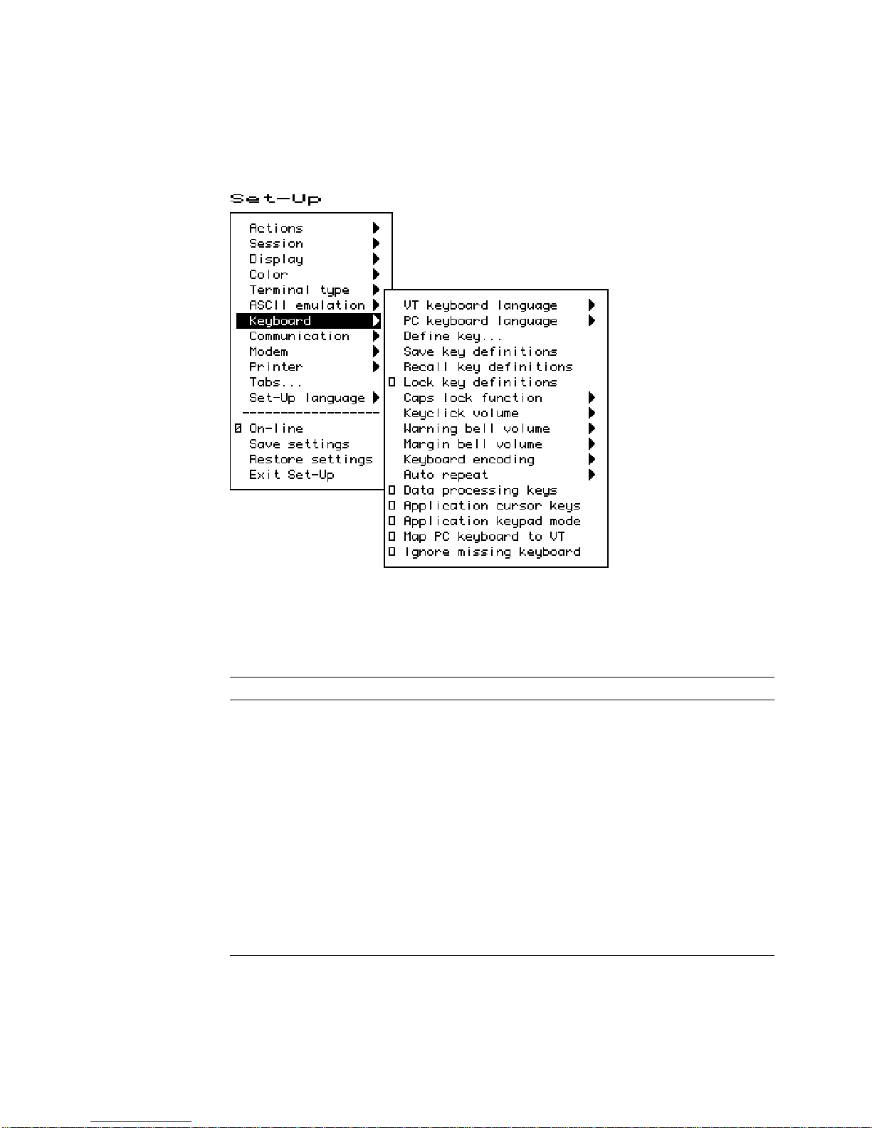
Set-Up
2.12 Keyboard Menu
2.12 Keyboard Menu
Figure 2–15 Keyboard Menu
Several of the features shown in Figure 2–15 are self-explanatory and correspond
directly to control functions listed in Table 2–7. For additional information, see
Chapters 4 and 5.
Table 2–7 Keyboard Features and Control Functions
Set-Up Feature Control Function
Keyboard language DECKBD
Switch between primary and
secondary keyboard language
Caps lock function DECLCK
Keyclick volume DECKCV
Warning bell volume DECWBV
Margin bell volume DECMBV
Keyboard encoding DECKPM
Auto repeat DECARM
Data processing keys DECKBUM
Application cursor keys DECCKM
Application keypad mode DECKPNM, DECKPAM, DECNKM
DECESKM (general), DECHEBM (Hebrew),
DECNAKB (Greek), DECCYRM (Cyrillic)
2–36 Set-Up
Page 69

2.12.1 Keyboard Language
Some keyboards allow you to select two different keyboard layouts and easily
switch between them (English and Hebrew, for example). This feature allows
the VT520 to support both existing conventions and emerging standards for
extending the graphic input and/or switching between languages in dual language
environments. (The North American keyboard has only one keyboard language,
English.)
The primary keyboard language corresponds to Group 1 (per DIN 2137) and
generally references the legends on the left half of the keytops.
The secondary keyboard language corresponds to Group 2 (Group Shift per DIN
2137) and generally references the legends on the right half of the keytops.
Set-Up
2.12 Keyboard Menu
Unless overridden,
Ctrl/Alt/F2
makes the secondary keyboard language active. (These are factory
defaults, standard on PCs.)
Selecting a new keyboard language in Set-Up automatically initializes the
keyboard character set, as described in Chapter 8.
Changes to this field take effect immediately. Changing this field to North
American or Dutch and then exiting Set-Up or going to another menu resets the
7-bit NRCS characters feature to disabled. There is no "7-bit characters" mode
for the North American or Dutch keyboards. This field affects the language of the
keyboard indicator line.
2.12.2 Define Key Editor
The Define Key Editor is an advanced function that allows the terminal to adapt
to environments that do not match the preprogrammed settings.
This function is designed to be easy to use; however, unless you
understand the consequences of remapping various key combinations,
use caution when using this feature.
The Define key menu invokes the Define Key Editor.
Ctrl/Alt/F1
makes the primary keyboard language active, and
Caution
To ensure consistent access to Set-Up features, the following rules apply for
interpreting keystrokes.
• Within Set-Up and the Define Key Editor, the four arrow keys along with
Enter,Return,Do,Select
standard definitions, regardless of how they may be redefined at other times.
The delete key will erase a field when defining an alphanumeric key. The one
exception is when pressing the key to be defined.
• When you pressF3as the first key after the terminal is powered on, you
always enter Set-Up, regardless of which keyboard you use or how
defined.
• When copying one key definition to another, the standard key definition for
a key is copied, not the current definition. This copy method ensures that
keyboard functions are not lost within the Define Key Editor.
and delete key <
x
are interpreted according to their
F3
Set-Up 2–37
is
Page 70

Set-Up
Return
; the Define Key Editor menu will appear.
2. Press the key for which you want to assign a new behavior. If the key
is a function key, a screen similar to Figure 2–16 is displayed. Names
are displayed in the Set-Up language selected (not according to keyboard
language). The ± symbol indicates a toggle feature. Names are truncated to
12 characters in the definition field.
3. Press
)
to highlight the Copy of key default radio button () and press
Enter
.
4. Press the key whose factory default behavior is what you want your defined
key to do.
5. Press
+
to highlight the OK or Apply button and press
Enter
.
2–38 Set-Up
2.12 Keyboard Menu
Figure 2–16 Define Key Editor, Select Function
MA−0324−93.GRA
2.12.2.1 Copy of Key Default—Moving a Standard Function
The simplest way to reprogram a key is to copy the behavior of another key. You
can use Copy of key default to copy the factory default for a key to be defined
to any position on the keyboard. You cannot, however, use this feature to edit the
code transmitted by individual keys. To move factory default key functions:
1. From the Keyboard menu item, select the Define key . . . function and
press
Page 71

2.12.2.2 Customization
If you want to program a key to behave differently than one of the factory defined
keys, then you will need to know about the following key categories:
Set-Up
2.12 Keyboard Menu
Function: Keys such as the arrow keys (*,+,(,)), the
Alphanumeric: Keys used to transmit alphanumeric characters.
Set-Up key, used to transmit function key sequences or to perform local
terminal functions.
2.12.2.3 Modifier Keys
Modifier keys vary from within the Function and Alphanumeric categories. A
modifier key is a key that modifies the behavior of other keys when it is pressed
and held down. For example, pressing an alphanumeric key in combination with
Shift
the
modifier key will normally send the shifted or uppercase characters for
that key.
Modifier keys are treated as a special kind of local terminal function. The VT520
function modifier keys are:
be modified by pressing
(Shift-2). Modifier keys themselves cannot normally be modified by other keys. A
key assigned to act as the
sequence when pressed in combination with
makes all assignable combinations of that key act as a modifier.
2.12.2.4 Creating a New Function
To define a new function key:
1. From the Keyboard menu item, select the Define key . . . function and
Return
press
; the Define Key Editor menu will appear.
2. Press the key for which you want to assign a new behavior.
Shift,Ctrl
Group Shift(Alt Gr
Shift
, and
modifier, for example, cannot transmit a function
Shift
modifier key, or the
Alt
. VT520 alphanumeric keys can also
on enhanced PC keyboards) and
Alt
. Defining a key as a modifier key
Alt/Shift
3. Press the
Enter
press
4. Press the
(
.
*
or
and
)
key to highlight the Function radio button () and
+
keys to highlight the modifier combination that you
want to define (Unshifted, Shifted, Control, and so on) and press
5. Press the
and
press
6. Press the
)
key to move to the Select function scroll box. Press the
+
keys to highlight the desired keystroke function from the list and
Enter
.
(
key to return to the Modifiers.
7. Repeat steps 4 through 6 to define other modifier combinations as desired.
8. Use the arrow keys (*,+,(,)) to highlight the OK or Apply button and
Enter
press
.
2.12.2.5 Examples of Creating New Functions
Examples of when to create new functions include:
x
• Changing the <
or
Delete
when shifted.
• Disabling the
Compose,Break
function.
Enter
.
key to delete when unshifted and to backspace
, and Set-Up keys by assigning them to have no
*
Set-Up 2–39
Page 72

Set-Up
2.12 Keyboard Menu
2.12.2.6 Correcting a Mistake
If you make a mistake or want to start over, choose the Cancel button. Use
Actions.Restore factory defaults to restore the factory default settings.
2.12.2.7 Creating A New Alphanumeric Key or Keyboard Layout
The method for creating a new alphanumeric key is similar to that for function
keys, except that you can define different modifier combinations and you enter
alphanumeric values differently.
If the key was previously programmed as a function key, the function definition
will be empty. Once any function definition is applied, all the alphanumeric
definitions for that key are lost. A single key cannot act as both a function key
and an alphanumeric key simultaneously.
To define a new alphanumeric key:
1. From the Keyboard menu item, select the Define key . . . function and
Return
press
2. Press the key for which you want to assign a new behavior.
; the Define Key Editor menu will appear.
3. Press the
and press
(
Enter
)
or
key to highlight the Alphanumeric radio button ()
. The character transmitted when this key is unshifted is
highlighted.
4. To select a different character, press the corresponding key on the keyboard,
or use the numeric compose key to generate a new character.
5. If desired, press the)key to move to the Non-spacing accent scroll box.
Press the
and press
*
Enter
and
.
+
keys to highlight any non-spacing accent from the list
6. The code transmitted by the unshifted alphanumeric key when pressed in
combination with the Control key is calculated automatically and displayed in
the Definition column. If desired, you may redefine this function.
7. If desired, select an Alt Function modifier combination for the alphanumeric
key from the Select Function scroll box. You may choose a function,
including a user-defined key (UDK) sequence. The default for the Alt
Function is None.
8. Press the(key to return to the modifier selection.
9. Use the arrow keys (*,+,(,)) to highlight the OK or Apply button and
Enter
press
.
To enter alphanumeric values you can type the desired character or numeral, you
can compose the desired character including numeric keypad compose, or you can
select a nonspacing accent from the nonspacing accent scroll box.
2.12.2.8 Examples of Creating New Alphanumeric Keys
Examples of when to create new alphanumeric keys include:
• Making the comma and period keys send comma and period instead of angle
brackets when shifted.
• Changing the keyboard from a QWERTY to QWERTZ layout.
• Defining an alternate key layout to match your own preference or local typing
conventions (Dvorak, or Russian Cyrillic, instead of Bulgarian Cyrillic).
2–40 Set-Up
Page 73

2.12.2.9 User-Defined Keys
The UDK radio button allows any key to be programmed with a user-defined
sequence. UDKs are a subset of function keys. A separate UDK dialog box is
provided for simplicity. Selecting UDK causes a UDK: text field to be displayed
so you can enter a key sequence. This text field can scroll left or right as needed
to allow longer strings to be entered.
Set-Up
2.12 Keyboard Menu
Enter control codes by holding the
decimal value for the code on the Numeric keypad. Codes may also be entered on
the Numeric keypad in column/row format as follows:
Compose 1 . 1 1
Press
+
again to move the highlighting cursor to select one of the following
UDK directions:
Normal The sequence is sent to the host and/or to the screen depending on
Terminal only The sequence is sent only to the screen, as if it had just been
Host only The sequence is sent only to the host, regardless of the
Press
+
again to select one of the following buttons:
OK Apply Cancel
When you select Cancel, you only cancel the changes to the currently selected
modifier combination.
2.12.2.10 Programming Notes
• When you pressF3as the first key after the terminal is powered on, you
always enter Set-Up, regardless of howF3is defined.
Compose
the communication settings (On-line, Local echo, Half duplex, and so
on).
received from the host.
communication settings.
Alt
or
key down and entering the
• The factory default Break function (unshifted F5) cannot be reprogrammed by
host control sequence. This is necessary to support secure attention. If the
sequence is received, the factory default keystroke table entry for Break is not
overwritten.
• If a key is programmed to act as a modifier key, it operates as a modifier with
any combination of
Shift,Alt
, or
Control
.
• If a key is programmed to be a modifier key and modifier key reporting is
enabled using DECSMKR, the key sends the VT sequence for the left modifier
key when there is more than one.
Caps Lock
•
combinations such as
extensions and cannot be reprogrammed by DECPFK. The
as a modifier. The
Caps Lock
Caps Lock/Print Screen
are local keyboard
Caps Lock
key acts
function can be moved to another key, but
Pause
must still send the Break.
• Use of the Define Key Editor to redefine keys on the numeric keypad affects
only the Num Lock off state of these keys. When Num Lock is engaged, these
keys will always send their factory default ASCII numerals (and related
characters) intended for numeric input. The Num Lock behavior of these
keys cannot be reprogrammed. (This Num Lock behavior does not apply to
numeric keypad mode on the VT keyboard or PC keyboard in VT style.)
Set-Up 2–41
Page 74

Set-Up
2.12 Keyboard Menu
• The toggle Num Lock function can be assigned to any single key combination.
Although the Num Lock state modifies other keys, the toggle Num Lock
function is not a modifier key. This means modifier combinations of
Num Lock/Key
• Use of the numeric keypad to compose characters by entering their decimal
code in combination with
work regardless of any reprogramming of keys on the numeric keypad, unless
such reprogramming directly conflicts with use of the keypad in this manner.
Example: A numeric keypad key has been defined as
• Function keys also work in VT100 mode.
2.12.3 Save Key Definitions
To save your key definitions so they will be available the next time you turn the
power on, select the Save key definitions menu item from the Keyboard menu.
This action field on the keyboard menu (Figure 2–15) causes the Define key
modifications to be saved to nonvolatile memory independently from any other
Set-Up features. Key definitions are saved on a first-come first-served basis and
are limited by the total amount of nonvolatile memory available.
This feature cannot be invoked by a host control function.
can be assigned to any other function or user-defined sequence.
Alt Gr
or
Compose
(held down) should continue to
Compose
or
Alt Gr
.
2.12.4 Recall Key Definitions
This action field causes previously saved Define key modifications to be recalled
from nonvolatile memory independently from any other Set-Up features.
2.12.5 Lock Key Definitions
The Lock key definitions menu item operates as a check box. When key
definitions are locked, they cannot be reprogrammed from the host.
2.12.6 Caps Lock Function
This function allows you to enable the
Caps lock Lock alpha keys on main keypad in uppercase setting.
Shift lock Lock alpha and numeric keys on main keypad in shifted setting.
Reverse lock Works the same as Caps Lock, except that pressing the
will send the lowercase or unshifted character assigned to a key.
Lock
or
Caps Lock
2.12.7 Keyclick, Warning Bell, and Margin Bell Volume
The volume of these settings can be set to high, low, or off, with high as the
default.
Suppress repeated warnings causes the terminal to ignore Control-G warning
bells encountered within two seconds of a previously sounded warning bell. When
using multiple sessions, this feature prevents broadcast messages sent to more
than one session from sounding the warning bell repeatedly for each session.
Alternatively, if several broadcast messages are pending in an inactive session,
the warning bell sounds once when the session is made active.
key to do the following:
Shift
key
2–42 Set-Up
Page 75

2.12.7.1 Visible Bell
The terminal provides a Visible bell feature, which flashes a bell ringing font
whenever a sound is generated. The fonts will flash six times and disappear in
2 seconds automatically. In ANSI mode, the bell is displayed at column 16 of
the keyboard indicator line (same place as the sticky keys indicator). In ASCII
mode, the bell is displayed at column 23 of the status line These bell fonts may
temporarily replace another indicator on the screen.
2.12.8 Keyboard Encoding
The Keyboard encoding menu allows you to select from the following:
Character (ASCII) The keyboard uses normal ANSI/ISO character encoding.
Scancode The terminal transmits make and break codes for each
Key position The keyboard transmits key position codes for each down
This feature corresponds to the DECKPM (key position mode) control function
described in Chapter 5.
Set-Up
2.12 Keyboard Menu
keystroke corresponding to the hardware scan codes used
by PC keyboards (scan set 1).
transition. This menu allows alternate keyboard layouts to be
supported by application software.
2.12.9 Auto Repeat
The Auto repeat feature selects whether keys begin auto repeating if still held
down after a delay interval:
Fast (30/sec)
Slow (10/sec)
Off
The repeat rate is the number of "keystrokes" per second, not characters per
second. Changes to this field take effect immediately.
This is a user-preference feature. When it is unlocked, this feature can be invoked
by the DECARM control function.
2.12.10 Data Processing Keys
This feature corresponds to the DECKBUM control function described in Chapter
5. Changes to this field take effect immediately.
2.12.11 Application Cursor Keys
This feature corresponds to the DECCKM control function described in Chapter
5. This feature is reset to the factory default setting by DECSTR.
Changes to this field take effect immediately.
Settings for Application cursor keys (AppCK) and Application keypad mode
(AppKM) selected in Set-Up can be saved to NVM and used as the power-on
settings. Settings for AppCK and AppKM selected by host control functions affect
the current operating state, as shown by the check boxes, but are not saved in the
NVM.
Set-Up 2–43
Page 76

Set-Up
2.12 Keyboard Menu
2.12.12 Application Keypad Mode
This feature selects whether the numeric keypad sends ASCII numerals or
application function sequences. It corresponds to the DECKPNM, DECKPAM,
and DECNKM control functions described in Chapter 5.
This field is reset to the power-up setting when a soft reset occurs (Reset Session
or receipt of DECSTR).
Changes to this field take effect immediately so you can use the keypad to enter
an Answerback message.
2.12.13 Map PC Keyboard to VT
Map PC keyboard to VT causes the terminal to treat a PC layout keyboard
as if it were a VT keyboard. F1-F5 behave as local function keys (Hold, Print,
Set-Up, Session, Break). Editing and numeric keypad keystrokes work the same
as the corresponding keys on a VT keyboard (PF1-PF4 are recognized instead of
NumLock and other PC legends).
This feature is only available when a PC keyboard is used and can be toggled on
or off by pressing CapsLock/NumLock.
2.12.14 Ignore Missing Keyboard
When selected, Ignore missing keyboard causes the terminal to ignore a
missing keyboard during power-up selftest instead of displaying a "Keyboard
error" message.
2–44 Set-Up
Page 77

2.13 Communication Menu
Figure 2–17 Communication Menu
Set-Up
2.13 Communication Menu
Several of the Communication features shown in Figure 2–17 are self-explanatory
and correspond directly to control functions listed in Table 2–8. These functions
are described in Chapter 5.
Table 2–8 Communication and Modem Features and Control Functions
Set-Up Feature Factory Default Host Control Code
Communication
Port select S1=comm1, S2=comm2,
Word size 8 bits DECSPP
Parity None DECSPP
Stop bits 1 bit DECSPP
Transmit speed 9600 DECSCS
Receive speed Transmit speed DECSCS
Transmit flow control XON/XOFF DECSFC
Receive flow control XON/XOFF or XPC DECSFC
Flow control threshold Low (64) -
.
DECSCP
Print=comm3
(continued on next page)
Set-Up 2–45
Page 78

Set-Up
2.13 Communication Menu
Table 2–8 (Cont.) Communication and Modem Features and Control Functions
Set-Up Feature Factory Default Host Control Code
Transmit rate limit 150 cps DECXRLM DECSTRL
Fkey rate limit 150 cps DECSTRL
[/] Ignore Null character DECNULM
[ ] Local echo SRM
[ ] Half duplex DECCHDPXM
[ ] Auto answerback Answerback message... DECLANS
[ ] Answerback concealed DECCANSM
Modem
.
[ ] Enable modem control DECMCM
Disconnect delay 2 seconds DECSDDT
Modem high speed Ignore Modem low speed Ignore -
2.13.1 Communication Port Select
The Communication.Port Select dialog box (Figure 2–18) allows you to
specify which of the VT520’s serial communication ports (comm1..comm3) are
used by each session. The sessions are identified across the top of the dialog box
with the session icon name.
Figure 2–18 Communications—Port Select
If more than one session is assigned to a single communications port, the
Terminal Device/Session Management Protocol (TD/SMP) is used. Pressing the
Session key (F4) cycles through each session 1 through 4 in order making it the
active session and establishing the corresponding connection as needed.
2–46 Set-Up
MA048493.GRA
Page 79

Set-Up
2.13 Communication Menu
If sessions are not yet enabled on the corresponding port, the TD/SMP enable
sessions command is issued and the first session connection on this port is
established. If the corresponding session connection has not yet been established
or the session is not the active session on this port, the TD/SMP open session
or select session command is sent. If opening a new session fails, the terminal
reverts back to the previous session.
Comm Radio Buttons
Selecting Comm = session off completely disables the corresponding session
virtual terminal such that it can no longer be made active, it is not included in
the switch session cycle order, and its icon does not appear in the framed windows
display. Resources previously assigned to this virtual terminal become available
to the others. At least one session must always be enabled. The terminal does not
allow "Comm = session off" to be set for the last remaining session. Notice that
selecting "Comm = session off" does not dim the corresponding session selection
in this dialog box.
Print Radio Buttons
This set of radio buttons control the printer port assignments. They are described
below with the Printer Port Select dialog box. This same dialog box appears in
both Communications and Printer Set-Up and affects all sessions. If comm3 is
assigned as the printer port for one or more sessions, it is dimmed and is not
available as a comm selection. Alternatively, if comm3 is assigned as the comm
port for any session, it is dimmed and is not available as a printer port selection.
The factory default is ‘‘Print=none’’ for all four sessions.
The Printer Port Select dialog box allows you to specify which port is to be
used for local print operations: serial port comm3 or the Centronics parallel port.
If more than one session is assigned to use a single printer port, the printer
will be shared on a first-come-first- served basis. The Print Page operation
and Printer Controller Mode can not be interrupted. If a session is using the
printer for either of these, other sessions attempting to use this printer port are
forced to wait (printer status: busy) until the previous operation completes. A
session assigned "Print = none" will have "printer status: no printer". Any print
operations attempted from this session will be ignored.
2.13.2 Word Size
The communication word size can be 8 bits (default) or 7 bits.
2.13.3 Parity
You can select any of the following parity checks:
2.13.4 Stop Bits
For communication, 1 (default) or 2 stop bits can be enabled.
None
Even
Odd
Even, unchecked
Odd, unchecked
Mark
Space
Set-Up 2–47
Page 80

Set-Up
2.13 Communication Menu
2.13.5 Transmit Speed
The communication Transmit speed is set to 9600 baud. You can select transmit
speeds from the menu shown in Figure 2–19.
Figure 2–19 Communication Transmit Speed Menu
2.13.6 Receive Speed
Like the communication Transmit speed, you can select the Receive speed
from 300 to 115.2K baud. The default receive speed matches the transmit speed
selection.
2.13.7 Transmit Flow Control
The Transmit flow control method can be one of the following:
None
XON/XOFF
DSR (Data Send Ready)
Both
When an ASCII emulation is selected, the default Transmit flow control
is None.
Note
2–48 Set-Up
Page 81

2.13.8 Receive Flow Control
The Receive flow control method can be one of the following:
None
XON/XOFF or XPC
DTR (Data Transmit Ready)
Both
2.13.9 Flow Control Threshold
You can set the Flow control threshold to Low (64 characters) or to High (768
characters).
2.13.10 Transmit Rate Limit, Fkey Rate Limit
The Transmit rate limit choice limits the character rate from the keyboard
to between 30 and 150 characters per second (selectable with fairly uniform
separation), regardless of baud rate. This is fast enough to allow any keystroke
to auto repeat at 30 Hz (baud rate permitting). The default is 150.
This feature allows you to limit the transmit rate from the terminal so as to
reduce the interrupt burden on the operating system.
You can select a different transmit rate for graphic keys and function keys using
Fkey rate limit. The F keys transmit more than 1 byte per key press. This
function may be selected through the DECXRLM and DECTRL control function.
Refer to Chapter 5, for details.
Set-Up
2.13 Communication Menu
Figure 2–20 Communication Fkey Rate Limit Menu
Set-Up 2–49
Page 82

Set-Up
2.13 Communication Menu
2.13.11 Ignore Null Character
The Ignore Null setting causes the terminal to discard Null characters
immediately without buffering them. This allows NUL to be used as a time
fill character to pace terminal output without overflowing the receive character
buffer. To pass NUL control codes to a printer, you must deselect the Ignore
Null character check box.
2.13.12 Local Echo
With Local echo enabled, most characters sent from the keyboard to the host
are also displayed on the screen. The answerback message and XON/XOFFs are
not echoed locally. Everything else is.
This feature corresponds to the SRM control function described in Chapter 5.
Local echo is different from the "Local" setting of On-line in the main
menu of the Set-Up directory. Local echo causes keystrokes to be echoed
on the screen, but it does not direct keyboard input to the ANSI parser,
which also updates the screen. Local echo is temporarily disabled when
the terminal is in either Local mode or Local Controller mode, because
the keyboard input is already being redirected to the screen through the
parser or to the printer.
Note
2.13.13 Half Duplex
You can enable or disable Half duplex communication. The default is disabled.
Half duplex communication is available only on the Comm1 communications port.
If communication is set for the Comm2 port, this feature is disabled (dimmed).
2.13.14 Auto Answerback
This item is used to enable or disable Auto answerback on power-up or upon
connection. The factory default is disabled.
2.13.15 Answerback Message
Each session can have an answerback message. The Answerback message . . .
menu item invokes a dialog box with a 30-character limit. All characters that
can be generated by the keyboard are legal in this field (including primary and
secondary keyboard language characters). As such, no errors are reported, except
when trying to enter more than 30 characters. In this case, the bell rings (if
enabled), and no more characters are accepted. The factory default message is no
message at all (a blank field).
If an Answerback message is currently defined, the message is displayed in the
text entry area. The
enter a new Answerback message.
<
x
Delete
or
key can then be used to delete backwards and
2–50 Set-Up
Page 83

Figure 2–21 Communication Answerback Dialog Box
Set-Up
2.13 Communication Menu
Control characters are displayed using the CRM font. Pressing
return character in the Answerback message. Pressing
cursor in the Answerback text field moves to the OK button.
The current Answerback message is displayed in the answerback dialog
box unless Answerback concealed is selected. In this case, the previous
Answerback message is not shown. Choosing the OK button to enter a new
Answerback message clears the Answerback concealed check box.
2.13.16 Answerback Concealed
Changes to this field take effect immediately. The factory default is disabled.
If disabled, the Answerback message is visible in Set-Up. If enabled, the message
is not visible and the text "<concealed>" replaces the message. The only way to
return this field to disabled (visible) is to enter a new message.
Return
enters a
+
with the highlighting
Set-Up 2–51
Page 84

Set-Up
2.14 Modem Menu
2.14 Modem Menu
Figure 2–22 Modem Menu
2.14.1 Enable Modem Control
The field allows you to select whether the additional hardware control signals
at the interface connector are used for modem control. Modem control disabled
is also referred to as "Data leads only." Refer to Chapter 9 for details on modem
control signals.
This feature corresponds to DECMCM in Chapter 5.
2.14.2 Disconnect Delay
When modem control is enabled, the Disconnect delay feature determines
the time allowed before the terminal disconnects from the communications line
when the received line signal detect (RLSD) is lost. Disconnect delay is in effect
only when RLSD (CD) is lost. If DSR is lost, the terminal performs a disconnect
immediately. The following selections are available:
2 seconds
60 ms
No disconnect
All countries except the United Kingdom should use a delay of 2 seconds. The 60
ms delay is for use in the United Kingdom.
If the VT520 detects a loss of carrier and you selected No disconnect, the VT520
ignores RLSD (CD) after the beginning of the connection.
If you try to disconnect and reconnect the line, the VT520 checks to "see" if RLSD
is asserted before granting the connection. Once it is connected, the terminal
ignores the loss of carrier.
You can select disconnect delay through Set-Up or through control function
DECDDT. Refer to Chapter 9 for details on the connect and disconnect process.
2–52 Set-Up
Page 85

2.14.3 Modem High Speed
Figure 2–23 Modem High Speed Menu
Set-Up
2.14 Modem Menu
When modem control is enabled, the speed indicator signal (SI) from the
modem may be used to select the communication rate. This feature sets the
communication rate to be used when the speed indicator line is "on." Selecting
Ignore causes the terminal to use its regular transmit and receive speeds as it
would when modem control is disabled.
This feature can be invoked by DECSCS.
2.14.4 Modem Low Speed
These selections are the same as the modem high speed selections shown in
Figure 2–23. When modem control is enabled, the speed indicator (SI) signal
from the modem may be used to select the communication rate. This feature sets
the communication rate to be used when the speed indicator line is "off." Selecting
Ignore causes the terminal to use its regular transmit and receive speed as it
would when modem control is disabled. This feature can be invoked by DECSCS.
Set-Up 2–53
Page 86

Set-Up
2.15 Printer Menu
2.15 Printer Menu
Figure 2–24 Printer Menu
Printer features shown in Figure 2–24 correspond to the control functions listed
in Table 2–9. These functions are described in Chapter 5 and Chapter 10.
2.15.1 Port Select
The Port select menu is the same one that appears in the Communication
menu (see Figure 2–18). It is displayed in both areas to be easy to find whether
you are selecting the printer port or the host port. Having a single feature avoids
complex interactions between printer port and host port selections.
2.15.2 Print Mode
The Print mode menu allows you to select the printer operating mode as follows:
Normal
Autoprint
Controller
2–54 Set-Up
Page 87

2.15 Printer Menu
Note
We recommend that you do not save the Controller mode selection in NVR
because this may result in a "hung" terminal if the printer does not have
DTR asserted.
Local echo is temporarily disabled when the terminal is in either Local
mode or Local Controller mode, because the keyboard input is already
being redirected to the screen through the parser or to the printer.
Table 2–9 Printer Features and Control Functions
Set-Up Feature Factory Default Host Control Code
Set-Up
Printer
.
Port select S1=comm1, S2=comm2,
Print=comm3
Print mode Normal MC
Printer type DEC ANSI DECSPRTT DECSDPT
DEC/ISO char sets National only DECSDPT
PC character sets PC International (437) DECSPPCS
Same as receive
Print extent Full page DECPEX
Print terminator None DECPFF
———————————–
Serial print speed 4800 baud DECSCS
[ ] 2-way communication MC
Transmit flow control XON/XOFF DECSFC
Receive flow control XON/XOFF DECSFC
Word size 8 bits DECSPP
Parity None DECSPP
Stop bits 1 bit DECSPP
DECSCP
2.15.3 Printer Type
You can select the printer type as follows:
DEC ANSI
IBM ProPrinter
DEC + IBM
2.15.4 Printer Character Sets
The printer character set menus allow you to match the characters printed to the
character sets the printer is capable of supporting.
Set-Up 2–55
Page 88

Set-Up
2.15 Printer Menu
2.15.4.1 DEC/ISO Character Sets
You can enable the character set categories shown in Figure 2–25.
Figure 2–25 DEC/ISO Character Sets Menu
2.15.4.2 PC Character Sets
The numbers in parentheses in this menu refer to standard PC code pages. Refer
to Chapter 10 for a listing of the PC character sets.
Same as receive—Use IBM ProPrinter sequences with control codes or
without host control codes.
2.15.5 Print Extent
This selection allows you to print a full page or just the scroll region.
2.15.6 Print Terminator
The print terminator can be None or FF (form feed).
2.15.7 Serial Print Speed
Like the Communication menu speed selection (see Figure 2–19), you can select
the serial printer speed from 300 to 115.2K baud. The default is 4800 baud.
2–56 Set-Up
Page 89

Figure 2–26 PC Character Sets Menu
Set-Up
2.15 Printer Menu
2.15.8 2-Way Communication
This item allows you to enable and disable bidirectional communications on the
serial printer port. The default is 2-way communication disabled.
2.15.9 Transmit Flow Control
The printer transmit flow control method can be one of the following:
None
XON/XOFF
DSR (Data Send Ready)
Both
2.15.10 Receive Flow Control
The printer receive flow control method can be one of the following:
None
XON/XOFF
DTR (Data Terminal Ready)
Both
2.15.11 Word Size
The printer word size can be 8 bits (default) or 7 bits.
Set-Up 2–57
Page 90

Set-Up
2.15 Printer Menu
2.15.12 Parity
You can select any of the following parity checks to the printer:
None
Even
Odd
Mark
Space
2.15.13 Stop Bits
For the printer, 1 (default) or 2 stop bits can be enabled.
2.15.14 Same as Receive
This item allows you to set the transmit speed to be the same as the receive speed
on the printer port.
2.16 Tabs . . .
The Tabs . . . menu item is used to invoke the Tab Set-Up dialog box, displaying
a 132-column tab ruler. Figure 2–27 shows that tab stops are indicated by the
letter T.
The highlighting cursor is initially displayed over the entire tab field. The normal
character cursor appears in column 1 of the tab field.
(
The
advances the cursor to the next tab stop in the tab field (if any). The character
cursor automatically wraps between the end of the first row and the beginning of
the second row in the tab field.
and
)
keys move the cursor within the tab field. Pressing
Tab
2–58 Set-Up
Page 91

Figure 2–27 Tab Set-Up Dialog Box
Set-Up
2.16 Tabs . . .
2.17 Sound
The labeled buttons allow you to clear all tabs or to set 8-column tabs directly. To
set individual tabs:
1. Position the cursor in the desired column.
2. Press
Enter
to set or clear a tab in that column.
Tab setting can also be invoked by the HTS and DECCTS control functions.
The VT520 is capable of producing a range of sound frequencies. Examples:
To communicate . . . Sound used
Power on 125 ms beep
Attention warning (also ^G) 125 ms beep
Programmable Alarm Four short beeps in rapid succession, pause 0.5
Sticky keys on Series of three rising notes (short beeps Eb Ab C)
Sticky keys off Series of three falling notes (C Ab Eb)
Hourly chime 125 ms beep
Keyclick 2 ms beep
Margin bell 125 ms beep
seconds repeat. Alarm 1 uses C. Alarm 2 uses Eb.
Set-Up 2–59
Page 92

Set-Up
2.17 Sound
Pnote
1 C5 14 C#6 1047
2 C#5 15 D6
3 D5 16 D#6
4 D#5(Eb) 632 17 E6
5 E5 18 F6
6 F5 19 F#6
7 F#5 20 G6
8 G5 21 G#6
9 G#5 847 22 A6
10 A5 23 A#6
11 A#5 944 24 B6
12 B5 25 C7
13 C6
Note ~F (Hz)
Pnote
Note ~F (Hz)
There is no local sound editor or customize dialog box as the terminal’s sound
capability is rather simple and does not justify sophisticated editing features. A
control function is defined to allow applications to generate custom sounds. The
general form is
ESC [ Pvolume ; Pduration ; Pnote ;... FINAL
Where:
Pvolume specifies the sound volume (0=off, 1-3=low, 4-7=high).
Pduration specifies the note duration in 1/32 of a second.
Pnote;...Pnote specifies one or more notes to sound at the specified volume
and duration (0=silent, 1=Eb, 2=Ab, 3=Bb, 4=C).
The final characters of the sequence are ,~ (2/12 7/14).
The terminal’s sound buffer can store 16 notes of specified volume and duration.
Additional sound controls are held in the communications input buffer invoking
receive data flow control as needed.
2–60 Set-Up
Page 93

2.18 Set-Up Factory Defaults
2.18 Set-Up Factory Defaults
Table 2–10 lists the default for the features in the Set-up Menu and their
corresponding host control code if available.
Table 2–10 Set-Up Factory Defaults
Set-Up Feature Factory Default Host Control Code
Set-Up
Actions
Session
Display
.
Clear display ED
Clear communications
Reset this session DECSTR RIS
Restore factory defaults
—————————–
Clock DECLTOD
Calculator
Show character sets
Banner message DECLBAN
.
Select session
Session name DECSWT DECSIN
Pages per session S1=3,S2=3 DECSPMA
Save settings for all
Restore settings for all
Copy settings from
Update session When available DECUS
.
Lines per screen 24, 25 or 26 DECSNLS
[ ] Auto resize DECARSM
Lines per page 24 lines x 3 pages DECSLPP
[ ] Review previous lines DECRPL
Columns per page 80 Columns DECCOLM
[/] Clear on change DECNCSM
Status display Local status DECSSDT
Scrolling mode Jump DECSCLM DECSSCLS
Screen background Dark DECSCNM
Cursor display Block DECSCUSR
[/] Blink
[/] Enable cursor DECTCEM
Cursor coupling
[/] Vertical coupling DECVCCM
[/] Page coupling DECPCCM
(continued on next page)
Set-Up 2–61
Page 94

Set-Up
2.18 Set-Up Factory Defaults
Table 2–10 (Cont.) Set-Up Factory Defaults
Set-Up Feature Factory Default Host Control Code
Cursor direction Left to right DECRLM
Copy direction Left to right DECRLCM
Zero 0 DECSZS
[ ] Auto wrap DECAWM
[ ] New line mode LNM
[ ] Lock user preferences
[ ] Show control characters CRM
CRT saver 15 minutes DECCRTSM
[/] Host wake-up DECHWUM
Energy saver 15 minutes DECEST
[ ] Overscan DECOSCNM
[ ] Framed windows
Screen alignment... DECALN
Color
.
Assign colors DECAC DECCTR
Alternate text colors DECATC
Define colors DECRSTS
Select color map ANSI SGR color DECSTGLT SGR
ASCII color mode Color
Blink and Bold style Foreground DECBBSM
Erase color Text background DECECM
Reverse and Blank attributes
[/] Intensity attributes
Terminal type
Emulation mode VT520... DECTME
Terminal ID to host VT520 DECTID
VT default char set ISO Latin-1 SCS
PCTerm character set PC International (437) DECPCTERM
[ ] 7-bit NRCS characters DECNRCM
[/] Transmit 7-bit controls S7C1T
ASCII emulation
Data lines 24 Lines
Pages 1 x Lines
Attribute Char
Write protect attributes
[ ] Blank
[ ] Underline
.
.
(mono model only)
(continued on next page)
2–62 Set-Up
Page 95

2.18 Set-Up Factory Defaults
Table 2–10 (Cont.) Set-Up Factory Defaults
Set-Up Feature Factory Default Host Control Code
[ ] Reverse
[ ] Blink
[/] Dim
[ ] Page edit
Received CR
[ ] Recognize DEL
[/] Enhance
[/] Autoscroll
[ ] Autopage
[/] Send ACK
[ ] Answerback mode
[/] TVI page-flip
[ ] Font load
Block mode Conversation
Block end US/CR
Set-Up
Keyboard
.
VT Keyboard language North American DECKBD
PC Keyboard language North American DECKBD
Define key... DECPFK DECPAK
DECUDK DECNUMLK
DECCAPSLK DECKLHIM
DECLL
Save key definitions
Recall key definitions
[ ] Lock key definitions DECPKA
Caps lock function Caps Lock DECSLCK
Keyclick volume High DECSKCV
Warning bell volume High DECSWBV
Suppress repeated warnings
Margin bell volume Off DECSMBV
Keyboard encoding Character (ASCII) DECPCTERM
Auto repeat Fast (30/sec) DECARM
[ ] Data processing keys DECBUM
[ ] Application cursor keys DECCKM
[ ] Application keypad mode DECPAM DECKPNM
[ ] Map PC keyboard to VT
[ ] Ignore missing keyboard
(continued on next page)
Set-Up 2–63
Page 96

Set-Up
2.18 Set-Up Factory Defaults
Table 2–10 (Cont.) Set-Up Factory Defaults
Set-Up Feature Factory Default Host Control Code
Communication
Port select S1=comm1, S2=comm2,
Word size 8 bits DECSPP
Parity None DECSPP
Stop bits 1 bit DECSPP
Transmit speed 9600 DECSCS
Receive speed Transmit speed DECSCS
Transmit flow control XON/XOFF DECSFC
Receive flow control XON/XOFF or XPC DECSFC
Flow control threshold Low (64)
Transmit rate limit 150 cps DECXRLM DECSTRL
Fkey rate limit 150 cps DECSTRL
[/] Ignore Null character DECNULM
[ ] Local echo SRM
[ ] Half duplex DECCHDPXM
[ ] Auto answerback
Answerback message... DECLANS
[ ] Answerback concealed DECCANSM
.
DECSCP
Print=comm3
Modem
Printer
.
[ ] Enable modem control DECMCM
Disconnect delay 2 seconds DECSDDT
Modem high speed Ignore
Modem low speed Ignore
.
Port select S1=comm1, S2=comm2,
Print=comm3
Print mode Normal MC
Printer type DEC ANSI DECSPRTT DECSDPT
DEC/ISO char sets National only DECSDPT
PC character sets PC International (437) DECSPPCS
Same as receive
Print extent Full page DECPEX
Print terminator None DECPFF
—————————–
Serial print speed 4800 baud DECSCS
DECSCP
(continued on next page)
2–64 Set-Up
Page 97

2.18 Set-Up Factory Defaults
Table 2–10 (Cont.) Set-Up Factory Defaults
Set-Up Feature Factory Default Host Control Code
[ ] 2-way communication MC
Transmit flow control XON/XOFF DECSFC
Receive flow control XON/XOFF DECSFC
Word size 8 bits DECSPP
Parity None DECSPP
Stop bits 1 bit DECSPP
Tabs...
Set-Up language
[/] On-line
Save settings
Restore settings
Exit set-Up
.
.
—————————–
.
.
.
.
DECST8C HTS
English DECSSL
Set-Up
Set-Up 2–65
Page 98

Page 99

3.1 Introduction
To enhance productivity, the VT520 provides local desktop features that can be
used at any time the terminal is powered up, even when the terminal is not
connected to a host. These features are:
• Calculator
• Clock
• Show character sets
• Banner message
• Copy and paste
This chapter describes these desktop features and their interaction with the
terminal.
3.2 Invoking Desktop Features
Overview
The local functions can be accessed through Set-Up or through a userprogrammable key combination. Chapter 2, Set-Up, describes how to invoke
these desktop features and how to assign a key combination to a specific feature.
When one is invoked, the screen is partially obscured by that feature. Pressing
Ctrl/Z,F10(Exit
screen contents.
), or
ESC
exits the current desktop feature and reveals the entire
3
Desktop Features
From the Actions menu, you can invoke Clock, Calculator, Show character
sets and the Banner message. When the feature is highlighted (displayed in
reverse video), press
of some keyboard features is provided, as well as how to implement the Copy
and Paste function. You can copy and paste within a session and between
sessions.
Enter
or
Return
to enable the feature. A quick start summary
Desktop Features 3–1
Page 100

Desktop Features
CtrlZ,F10,Exit
, or
Esc
to exit the feature.
3.3 Calculator
You can enable the Calculator function in Set-Up by pressing
Caps Lock Alt/F12
if you are not in an ASCII emulation mode.
When you select the Calculator function, the terminal displays a simple
calculator. See the leftmost layout in Figures 3–1 and 3–2. The keypad keys map
directly to the calculator keys. The layout depends on whether a VT or Enhanced
PC keyboard is attached, and whether a modifier key (
ShiftorAlt
) is currently
held down.
When a keypad key is pressed, the corresponding key is highlighted (shown
in reverse video) on the screen. If a modifier key is pressed down, the display
changes to show the new keypad assignment. See the two rightmost layouts in
Figures 3–1 and 3–2. All keys not associated with the calculator are ignored.
3–2 Desktop Features
3.2 Invoking Desktop Features
While these desktop features are enabled, other terminal functions are disabled.
Press
MA049193.GRA
 Loading...