

Digital Equipment VT50, VT52 Service Manual
VT50/VT52
Pocket
Service
Guide

E
K-VT502-PG-001
VT50/VT52
Pocket Service Guide
digital
equipment
corporation • maynard.
massachusetts
1st Edition, January
1979
Copyright ©
1979
by Digital Equipment Corporation
The material in this manual
is
for informational
purposes and
is
subject to change without notice.
Digital Equipment Corporation assumes no re-
sponsibility for any errors which may appear
in
this manual.
Printed in U.S.A.
The following are trademarks
of
Digital Equipment
Corporation, Maynard, Massachusetts:
DEC DECtape
DECCOMM DECUS
DECsystem-lO DIGITAL
DECSYSTEM-20 MASSBUS
UNIBUS
PDP
RSTS
TYPESET-8
TYPESETcll
CONTENTS
1
INTRODt:CTION
1.1
Purpose
.....................................
.
1.2 Reference Documentation
.....................
.
2 TROUBLESHOOTING
2.1
Troubleshooting Philosophy. . . . . . . . . . . . . . . . . . . . 2
3 REMOVAL AND
REPLACEMENT
3.1 Removing and Replacing the
EIA
or 20
rnA
Adapter
Card.
. . . . . . . . . . . . . . . .
..
. .
..
15
3.2 Removing and Replacing the Power Supply/
Monitor Assembly
Heat
Sink Panel. . . . . . . . . . . . . 16
3.3 Removing and Replacing the Base
Assembly . . . . . . . . . . . . . . . . . . . . . . . . . . . . . . . . . . . . 17
3.4 Removing and Replacing the Character
Generator. . . . . . . . . . . . . . . . . . . . . . . . . . . . . . . . . . . . 18
3.5 Removing and Replacing the
Printer
Interface Option. . . . . . . . . . . . . . . . . . . . . . . . . . . . . . 19
3.6 Removing and Replacing the
RUT
and
DP
Modules
....
. . . . . . . . . . . . . . . . . . . . . . . . . . .
..
20
3.7 Removing and Replacing the Anti-Static
Ground
Shield...
. .
..
. . . . . . . . . . . . . . . . . . . . . . . . .
21
3.8 Removing and Replacing the Keyboard. . . . . . . .
..
22
3.9 Removing and Replacing the
Power
Supply/Monitor Assembly. . . . . . . . . . . . . . . . . . .
..
23
3.10 Removing and Replacing the CRT
Assembly. . . . . . . . . . . . . . . . . . . . . . . . . . . . . . . . . .
..
26
3.11 Removing and Replacing the CRT Yoke. .
..
. . .
..
27
3.12 Removing and Replacing the Electrolytic
Copier
Option. . . . . . . . . . . . . . . . . . . . . . . . . . . . . .
..
28
3.13 Removing and Replacing the Transformer
Assembly. . . . . . . . . . . . . . . . . . . . . . . . . . . . . . . . . . . . 29
iii

iv CONTENTS
4 ALIGNMENT AND
ADJUSTMENTS
4.1
CRT
Yoke Alignment
........................
.
4.2 Display Adjustments
.........................
.
5 ACCEPTANCE
TEST
PROCEDURES
5.1
General. . . . . . . . . . . . . . . . . . . . . . . . . . . . . . . . . . . .
..
33
5.2
Terminal
Tests.
. . . . . . . . . . . . . . . . . . . . . . . . . . . . . . 33
5.3
Copier Option Tests. . . . . . . . . . . . . . . . . . . . . . . . .
..
36
5.4 Printer Interface Option
Tests.
. . . . . . . . . . . . . . .
..
36
6 INSTALLATION
A:"oID
OPERATION
6.1
Installation. . . . . . . . . . . . . . . . . . . . . . . . . . . . . . . . . . . 3 7
6.2
Operation. . . . . . . . . . . . . . . . . . . . . . . . . . . . . . . . . . . . 37
7 PMK04 OPERATION
APPENDIX
A CARE AND HANDLING
OF
CATHODE
RAY
TUBES
APPENDIX
B REPLACEABLE
:\10DULES
AND ASSEMBLIES PARTS LIST
FIGURES
2-1
Troubleshooting Procedures Index
..............
2-2
ROM
Chip Locations
.........................
2-3 Jumper
W7
Location
..........................
3-1
Removal and Replacement Guide
...............
3-2 Removing and Replacing the
EIA
or
20 rnA Adapter
Card
..........................
3-3 Removing and Replacing the Power
Supply/Monitor Assembly
Heat
Sink Panel
......
3-4 Removing and Replacing the Base
Assembly
....................................
3-5
Removing and Replacing the Character
Generator and Optional
Printer Interface
Module
......................................
3-6
Removing and Replacing the
RUT
and
DP
Modules
.................................
'
3-7
Removing and Replacing the Keyboard
.........
3
14
15
16
18
19
20
22

CONTENTS v
3-8 Removing and Replacing the Power
Supply/Monitor Assembly
.....................
23
,9
Discharging the
CRT
and Power Supply
Capacitors
...................................
24
3-10
Power Supply/Monitor Assembly
Capacitor Connections
........................
25
3-11
Installing the Power Supply /Monitor
Board Assembly
..............................
26
3-12 Removing and Replacing the CRT Assembly
.....
27
3-13 Removing and Replacing the Electrolytic
Copier
Option
................................
28
3-14
Copier
Power and Signal Connectors
............
29
3-15
Transformer Assembly Wiring Diagram
.........
30
4-1
Yoke Alignment
..............................
31
4-2 Display Adjustments
..........................
32
6-1
Function and Baud Rate Switch Settings
.........
38
6-2
Power
ON/OFF
Switch and Intensity Control
Locations
....................................
38
B-1
VT52 Replaceable Modules and
Assemblies/Parts List
.........................
46
C-l
Physical/Functional Block Diagram
.............
47
TABLES
2-1
Power on Troubleshooting Procedure. . . . . . . . . . . . 4
2-2 Character Display Troubleshooting
Procedure. . . . . . . . . . . . . . . . . . . . . . . . . . . . . . . . . . . . 7
2-3
Display Troubleshooting Procedure . . . . . . . . . . . . . 9
~-4
Copier Option Troubleshooting Procedure
..
. . . . .
11
l-5 Printer Interface Option Troubleshooting
Procedure. . . . . . . . . . . . . . . . . . . . . . . . . . . . . . . . . . . . 12
2-6 Printer Interface
Option Baud Rate Selection. . . . .
13
7-2 7-Bit ASCII
Code.
. . . . . . . . . . . . . . . . . . . . . . . . . . .
40

1 INTRODUCTION
1.1
PURPOSE
The purpose
of
this Pocket Service Guide
is
to provide Field Service engineers and technicians with a convenient
source
of
"memory
jogger"
reference
information for the VT50 and VT52 terminals. This in-
formation supplements detailed operation
and
mainte-
nance
information
contained
in
the
reference
documentation listed in Paragraph
1.2.
1.2 REFERENCE DOCUMENTATION
Document
VT52 DECscope Maintenance
Manual
DECscope User's Manual
PMK04 Operating and Service
Manual
Document No.
EK-VT52-MM-OOI
EK-
VT5X-OP-OOI
EK-PMK04-05-001
2 TROUBLESHOOTING
2.1
TROUBLESHOOTING
PHILOSOPHY
NOTE
Before attempting to troubleshoot the terminal ensure that
there actually
is
a malfunction by checking that the unit is
properly set
up
for operation with a host computer (Chap-
ter 6).
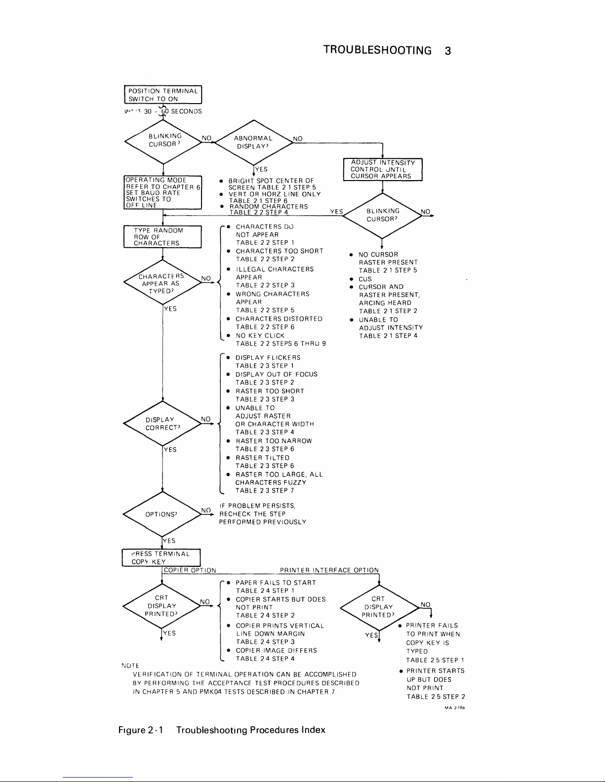
Figure
2-1
is
an index to the troubleshooting pro-
cedures contained in Tables
2-1
through 2-5. Step-by-
step turn-on
and
operating instructions are followed by
normal display indications.
If
these indications are ab-
sent
or
incorrect, refer
to
the corresponding tables for
troubleshooting information.
Possible equipment malfunctions are categorized by
abnormal symptoms. Corresponding causes are listed in
order
of
probability. Corrective actions are limited
mainly
to
the adjustments
and/or
substitutions
of
major
replaceable subassemblies suspected to be defective.
If after performing the off-line tests described
in
this
chapter the terminal functions properly
but
still does
not
operate correctly when connected to a host computer,
verify
that
portion
of
the terminal
not
checked by offline tests and the interface cabling with the PMK04
tester (Chapter
6).
2
TROUBLESHOOTING 3
YES
NOTE
NO
•
BRIGHT
SPOT
CENTER
OF
SCREEN
TABLE
21
STEP 5
•
VERT
OR
HORZ
LINE
ONLY
TABLE
21
STEP
6
•
RANDOM
CHARACTERS
TABLE
22
STEP 4
• CHARACTE
RS
Du
NOT
APPEAR
TABLE
22
STEP
1
•
CHARACTERS
TOO
SHORT
TABLE
22
STEP
2
• I
LLEGAL
CHARACTERS
APPEAR
TABLE
22
STEP
3
• WRONG
CHARACTERS
APPEAR
TABLE
22
STEP 5
•
CHARACTERS
DISTORTED
TABLE
22
STEP 6
• NO KEY
CLICK
TABLE
22
STEPS 6 THRU
9
• DISPLAY
FLICKERS
TABLE
23STEP
1
• DISPLAY OUT OF FOCUS
TABLE
2·3
STEP 2
•
RASTER
TOO
SHORT
TABLE
23
STEP 3
•
UNABLE
TO
ADJUST
RASTER
OR
CHARACTER
WIDTH
TABLE
23
STEP 4
• RASTE R
TOO
NAR
ROW
TABLE
23
STEP 6
•
RASTER
TILTED
TABLE
23
STEP
6
• RASTER
TOO
LARGE.
ALL
CHARACTERS
FUZZY
TABLE
23
STEP 7
IF PROBLEM PERSISTS,
RECHECK THE
STEP
PERFORMED
PREVIOUSLY
PAPER
FAILS
TO
START
TABLE
24
STEP
1
COPIER STARTS
BUT
DOES
NOT PRINT
TABLE
24
STEP
2
COPIER PRINTS
VERTICAL
LINE
DOWN
MARGIN
TABLE
24
STEP
3
COPIER IMAGE DIFFERS
TABLE
24
STEP 4
•
NO
CURSOR
RASTER
PRESENT
TABLE
21
STEP
5
• CUs
• CURSOR
AND
RASTER
PRESENT,
ARCING
HEARD
TABLE
2·'
STEP
2
•
UNABLE
TO
ADJUST INTENSITY
TABLE
2'
STEP
4
TYPED
TABLE
25
STEP'
VERIFICATION
OF
TERMINAL
OPERATION CAN
BE
ACCOMPLISHED
BY PERFORMING THE ACCEPTANCE TEST PROCEDURES DESCRIBED
IN
CHAPTER 5
AND
PMK04 TESTS DESCRIBED
IN
CHAPTER 7
• PRINTER STARTS
UP
BUT DOES
NOT
PRINT
TABLE
2·5
STEP
2
Figure 2-1 Troubleshooting Procedures Index

4 TROUBLESHOOTING
Table
2-1 Power
On
Troubleshooting Procedure
Symptom
I.
No
cursor
2.
No
cursor;
no
raster
WARNING
Possible
Cause
Unit
not
plugged
into
power
source
Intensity
control
turned
down
Blown fuse
or
tripped
circuit
breaker
Corrective Action
Plug
unit
into
appropriate
source
of
prime
power.
Adjust
intensity
control
(Paragraph
6.2).
Replace
fuse
or
reset
circuit
breaker.
No
prime
power
at
Restore
source
of
power
receptacle
prime
power.
There
are
high voltages present in the power supply and
CRT.
Ensure
that
the terminal power line is unplugged and the
CRT
and capacitors
are
discharged (Figure 3-9) before handling the
power supply
or
CRT
components. Ensure
that
ground connection
is made before discharging these points.
Defective
power
supply/monitor
assembly
Defective high
voltage
diode
assembly
Anode
cap
disconnected
Anode
clip
disconnected
Defective
ON/OFF
switch
Replace
power
supply
/monitor
assembly
(Paragraph
3.9).
Replace high
voltage
diode
assembly
(Figure
3-8).
Connect
anode
cap
at
power
supply
(Paragraph
3.2
and
Figure
3-8).
Connect
anode
clip
at
CRT
bell
(Paragraph
3.6
and
Figure
3-12).
Replace
transformer
assembly
(Paragraph
3.13).
TROUBLESHOOTING 5
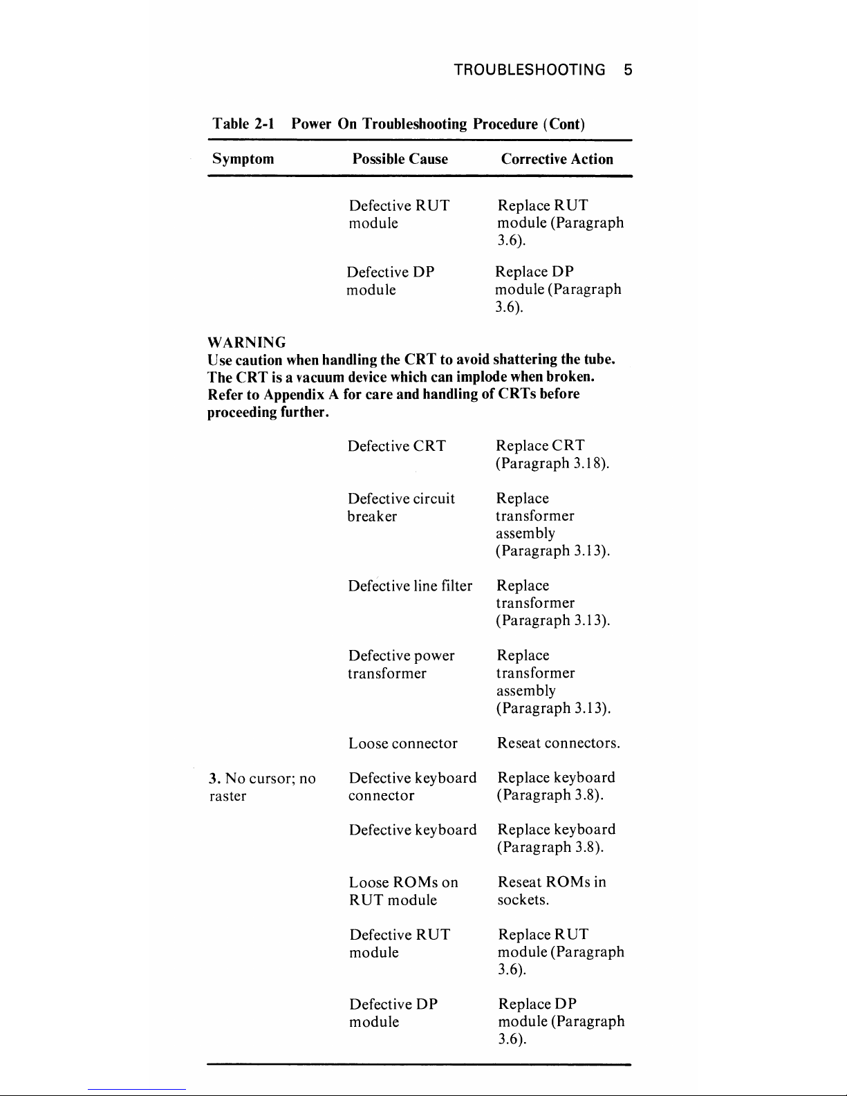
Table
2-1 Power On Troubleshooting Procedure (Cont)
Symptom
WARNING
Possible Cause
Defective
RUT
module
Defective
DP
module
Corrective Action
Replace
RUT
module
(Paragraph
3.6).
ReplaceDP
module
(Paragraph
3.6).
Use caution when handling the
CRT
to avoid shattering the tube.
The
CRT
is a vacuum device which can implode when broken.
Refer to Appendix A for
care
and handling
of
CRTs
before
proceeding further.
Defective
CRT
Replace
CRT
(Paragraph
3.18).
Defective circuit Replace
breaker
transformer
assembly
(Paragraph
3.13).
Defective line filter
Replace
transformer
(Paragraph
3.13).
Defective
power
Replace
transformer
transformer
assembly
(Paragraph
3.13).
Loose
connector
Reseat connectors.
3.
No
cursor; no
Defective
keyboard
Replace
keyboard
raster
connector
(Paragraph
3.8).
Defective
keyboard
Replace
keyboard
(Paragraph
3.8).
Loose
ROMs
on
Reseat
ROMs
in
RUT
module
sockets.
Defective
RUT
Replace
RUT
module
module
(Paragraph
3.6).
Defective
DP
ReplaceDP
module
module
(Paragraph
3.6).
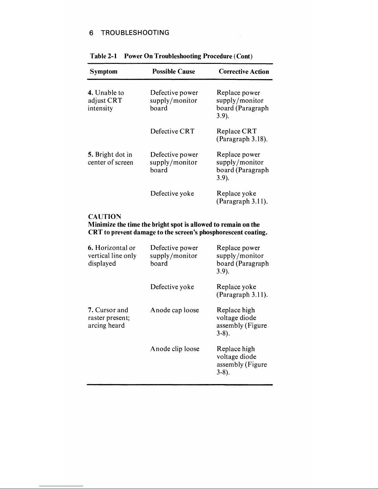
6 TROUBLESHOOTING
Table
2-1
Power On Troubleshooting Procedure (Cont)
Symptom Possible Cause
Corrective Action
4.
Unable to
Defective power Replace power
adjust
CRT
supply/monitor
supply
/monitor
intensity board board (Paragraph
3.9).
Defective
CRT
Replace
CRT
(Paragraph 3.18).
5. Bright dot
in
Defective power Replace power
center 0 f screen supply
/monitor
supply
/monitor
board
board
(Paragraph
3.9).
Defective yoke Replace yoke
(Paragraph 3.11).
CAlJTION
Minimize the time the bright spot
is
allowed to remain on the
CRT to prevent damage to the screen's phosphorescent coating.
6. Horizontal
or
vertical line only
displayed
7.
Cursor and
raster presen
t;
arcing heard
Defective power
supply
/monitor
board
Defective yoke
Anode cap loose
Anode clip loose
Replace power
supply
/monitor
board (Paragraph
3.9).
Replace yoke
(Paragraph 3.11).
Replace high
voltage diode
assembly (Figure
3-8).
Replace high
voltage diode
assembly (Figure
3-8).
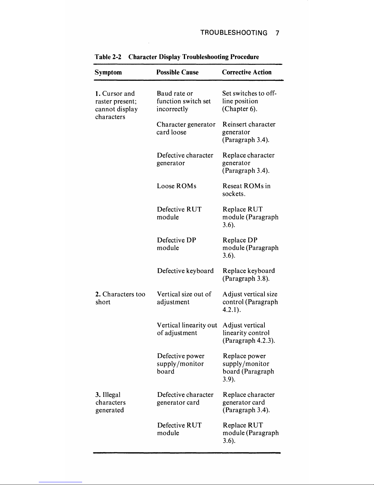
TROUBLESHOOTING
7
Table 2-2
Character Display Troubleshooting Procedure
Symptom Possible Cause Corrective Action
1. Cursor and
Baud rate
or
Set switches to off-
raster present; function switch set
line position
cannot display
incorrectly (Chapter 6).
characters
Character generator
Reinsert character
card loose
generator
(Paragraph 3.4).
Defective character Replace character
generator generator
(Paragraph 3.4).
Loose
ROMs
Reseat
ROMs
in
sockets.
Defective
RUT
Replace
RUT
module
module
(Paragraph
3.6).
Defective
DP
Replace
DP
module
module
(Paragraph
3.6).
Defective keyboard
Replace keyboard
(Paragraph 3.8).
2. Characters too Vertical size out
of
Adjust vertical size
short adjustment
control
(Paragraph
4.2.1).
V erticallinearity
out
Adjust vertical
of
adjustment linearity control
(Paragraph 4.2.3).
Defective power Replace power
supply
/monitor
supply
/monitor
board
board (Paragraph
3.9).
3. Illegal
Defective character
Replace character
characters generator card generator card
generated
(Paragraph 3.4).
Defective
RUT
Replace
RUT
module
module
(Paragraph
3.6).
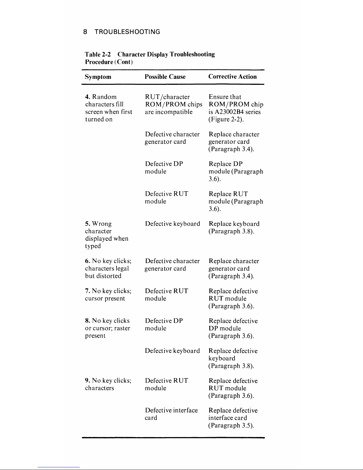
8 TROUBLESHOOTING
Table 2-2
Character
Display Troubleshooting
Procedure (Cont)
Symptom
4.
Random
characters
fill
screen when first
turned
on
5.
Wrong
character
displayed when
typed
6.
No
key clicks;
characters
legal
but
distorted
7.
:-;0
key clicks;
cursor
present
8.
No
key clicks
or
cursor; raster
present
9.
No
key clicks;
characters
Possible Cause
RUT
/character
ROM/PROM
chips
are
incompatible
Defective
character
generator
card
Defective
DP
module
Defective
RUT
module
Defective
keyboard
Defective
character
generator
card
Defective
RUT
module
Defective
DP
module
Defective
keyboard
Defective
RUT
module
Defective interface
card
Corrective Action
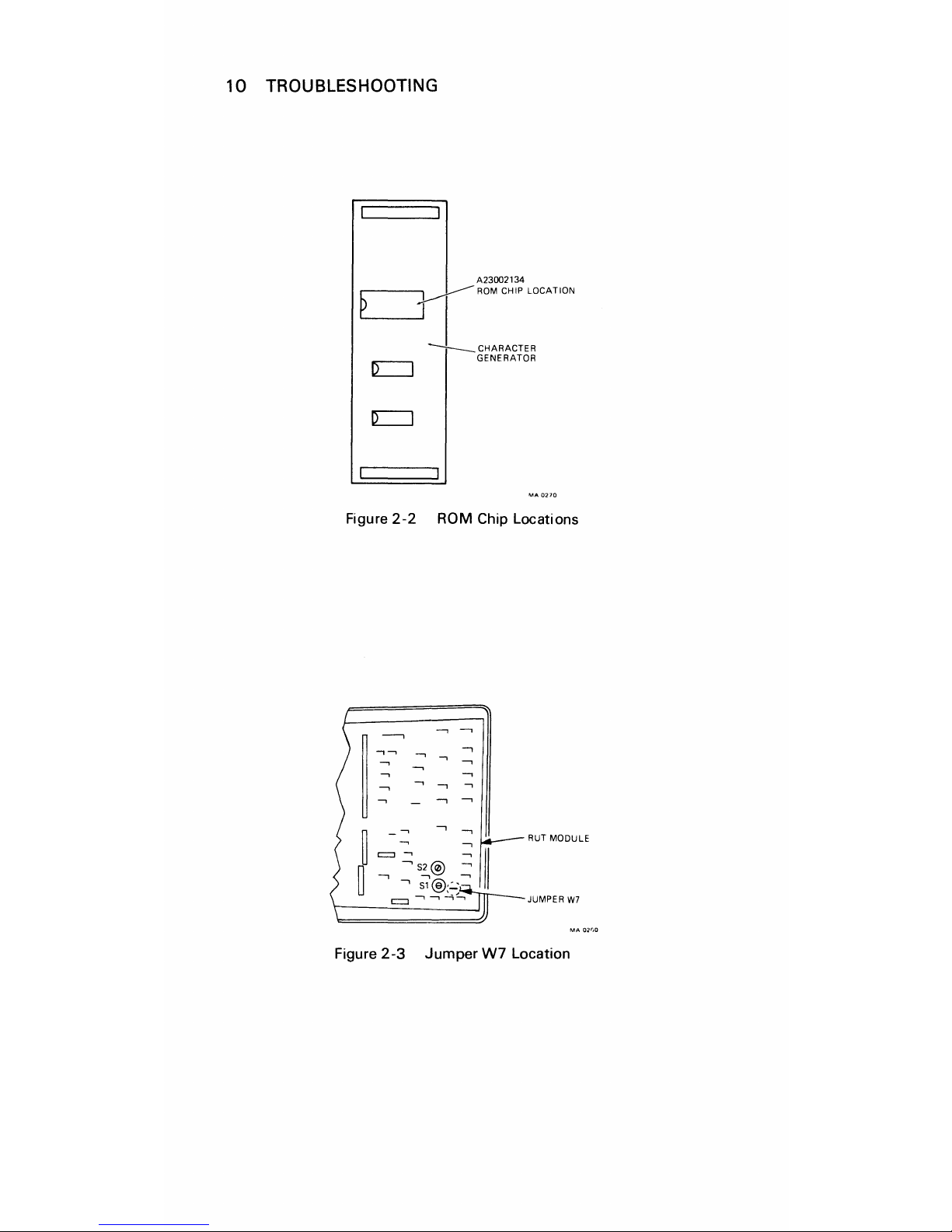
Ensure
that
ROM/PROM
chip
is
A23002B4 series
(Figure
2-2).
Replace
character
generator
card
(Paragraph
3.4).
Replace
DP
module
(Paragraph
3.6).
Replace
RUT
module
(Paragraph
3.6).
Replace
keyboard
(Paragraph
3.8).
Replace
character
generator
card
(Paragraph
3.4).
Replace defective
RUT
module
(Paragraph
3.6).
Replace defective
DPmodule
(Paragraph
3.6).
Replace defective
keyboard
(Paragraph
3.8).
Replace defective
RUT
module
(Paragraph
3.6).
Replace defective
interface
card
(Paragraph
3.5).
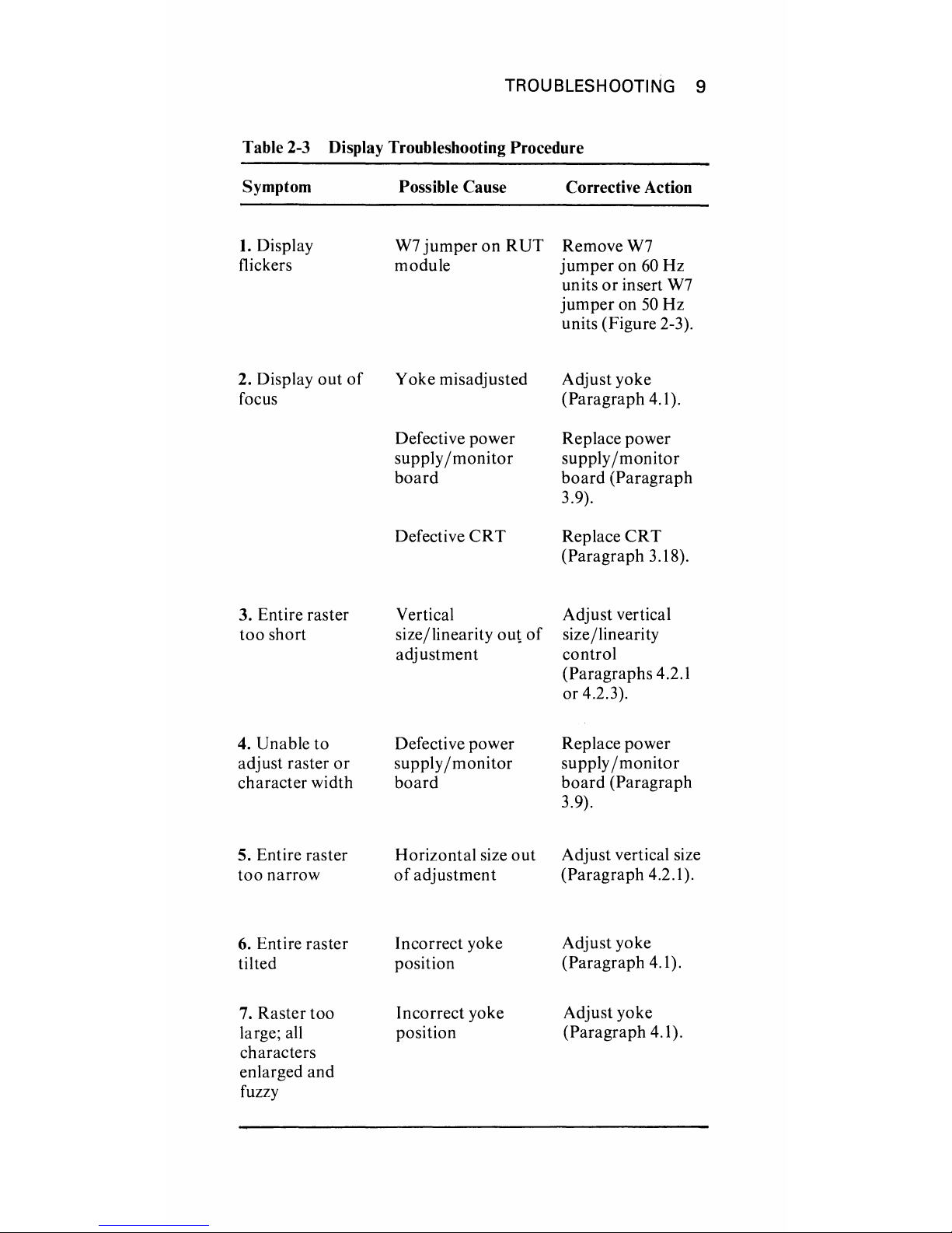
TROUBLESHOOTING
9
Table 2-3 Display Troubleshooting Procedure
Symptom
Possible Cause
Corrective Action
I.
Display
W7
jumper
on
RUT
RemoveW7
flickers module
jumper
on
60 Hz
units
or
insert W7
jumper
on
50
Hz
units (Figure 2-3).
2. Display
out
of
Yoke misadjusted Adjust yoke
focus
(Paragraph 4.1).
Defective power
Replace power
supply
/monitor
supply
/monitor
board
board
(Paragraph
3.9).
Defective
CRT
Replace
CRT
(Paragraph 3.18).
3. Entire raster Vertical Adjust vertical
too
short
size/linearity
out
of
size/linearity
adjustment
control
(Paragraphs 4.2.1
or 4.2.3).
4. Unable to Defective power Replace power
adjust raster
or
supply/monitor
supply
/monitor
character width
board board
(Paragraph
3.9).
5. Entire raster Horizontal size
out
Adjust vertical size
too narrow
of
adjustment (Paragraph 4.2.1).
6. Entire raster Incorrect yoke
Adjust yoke
tilted position
(Paragraph 4.1).
7. Raster too Incorrect yoke
Adjust yoke
large; all
position
(Paragraph 4.1).
characters
enlarged and
fULlY
10
TROUBLESHOOTING
A23002134
C=:3
------
ROM
CH"
LOCATIO'
~CHARACTER
GENERATOR
Figure
2-2
ROM
Chip Locations
Figure
2-3
Jumper
W7
Location
 Loading...