

Digital Equipment EK-VT100-UG-001, VT100 User Manual


VT100
USER
GUIDE
EK-VT100-UG-001

1
st
Edition, August 1978
Copyright @
The
material in this manual is for informational purposes and
is subject
1978
to
by Digital Equipment Corporation
change
without
notice.
Digital Equipment Corporation assumes no responsibility
any errors
Printed
This
puterized
The
Maynard. Massachusetts:
which
in
U.S.A.
document
typesetting
following are trademarks
may appear in this manual.
was
set
on
system.
DIGITAL's
of
Digital Equipment Corporation.
DECset-8000
for
com-
DIGITAL
DEC
PDP
DECUS
UNIBUS
ii
DECsystem-10
DECSYSTEM-20
DIBOL
EDUSYSTEM
VAX
VMS
MASS BUS
OMNIBUS
OS/8
RSTS
RSX
lAS
CONTENTS
Page
CHAPTER
PART 1 - KEYBOARD CONTROLS AND INDICATORS ..........................................
PART 2 -
1
SET-UP
SET-U P Features
SET -U P A ................................................................................................................ 1-7
OPERATOR
INFORMATION
MODE ............................................................................................... 1-7
at
a Glance ............................................................................... 1-7
SET-UP.B .................................................................................................................
Determining
How
to Change a SET-UP Feature ...................................................................
SETTING THE
SAVING
RECALLING SET-UP FEATURES ...............................................................................
RESETTING
PART 3 PART 4 - SELF-TESTING
PART 5 -
SET-UP FEATURES ......................................................................................
DEFINITION
Self-Test Error Codes ..........................................................................................
WHAT
CHAPTER
SITE CONSiDERATIONS ...............................................................................................
UNPACKING
USER MAINTENANCE ...................................................................................................
INTERFACE
EIA Interface ...........................................................................................................
Electrical Characteristics .......................................................................................
What
a SET-UP Feature Does ......................................................
ANSWERBACK
THE
TERMINAL. .....................................................................................
OF EACH
TO
DO IN THE EVENT
2
INSTALLATION,
AND
AND
INSTALLATION .............................................................................
INFORMATION
MESSAGE ..............................................................
THE
SET-'-UP
VT1
00
FEATURE .............................................
......................................................................
OF
A PROBLEM ....................................
INTERFACE
INFORMATION,
SPECIFICATIONS
.........................................................................................
1-10
1-12
1-12
1-13
1-13
1-13
1-15
1-15
1-16
1-4
1-8
1-9
2-3
2-3
2-6
2-6
2-6
2-7
iii
CONTENTS
(CONT)
Page
iv
OPTIONAL
EXTERNAL VIDEO CONNECTIONS .............................................................................
VT100
HOW
CHAPTER
THE
KEyBOARD ..............................................................................................................
COMMUNICATION PROTOCOLS .............................................................................
TERMINAL
ANSI COMPATIBLE MODE ........................................................................................
REPORTS ......................................................................... ; ..............................................
VALID
20
mA
CURRENT LOOP INTERFACE .....................................................
Electrica I Characteristics .......................................................................................
Composite Video Output (J9) ..............................................................................
Video
Input
(J8) ...................................................................................................
SPECiFiCATIONS ........................................................................................... .2-1 0
TO
ORDER
Control
Escape Sequences ...............................................................................................
Cursor
Line
Size
Character A ttri butes ............................................................................................
Erasing ...................................................................................................................
Programmable LEDs ...........................................................................................
Character Sets
Scrolling Region ......... : .........................................................................................
Tab Stops ..............................................................................................................
Modes ....................................................................................................................
Cursor Position Report. .......................................................................................
Status Report .......................................................................................................
What
Reset ......................................................................................................................
Confidence Tests .................................................................................................
ANSI
CPR Cursor Position Report CU
B Cursor Backward - Host
CU
D Cursor
CUF Cursor Forward - Host
CUP Cursor Position .........................................................................................
CUU Cursor Up - Host
DA
Device
DECALN Screen
DECANM
DECARM
DECAWM
D
ECCO
DECCKM Cursor Keys Mode (DEC Private) ..................................................
DECDHL Double Height Line (DEC Private) .................................................
HARDWARE
3
CONTROL
Are You .......................................................................................................
PROGRAMMER'S
COMMANDS
Cha
racters ...............................................................................................
Movement
(Double-height and Double-width) Commands ............................
MODE ESCAPE SEQUENCES (detailed) ...........................................
LM
Commands ...........................................................................
(GO
Down -Host
Attributes
Alignment
ANSI/VT52
Auto
Repeat
Autowrap
Column
DOCUMENTATION ..............................................
INFORMATION
........................................................................
and G 1 Designators) ........................................................
to
to
VT100
...................
Mode
Mode
Mode
Mode
(D
VT100
to
VT100
to
Display (DEC Private) .....................................
(DEC
(DEC Private) ................................................
(DEC Private) ....................................................
EC
to
Host.. ............................................
VT100
VT100
and
'"
Private) .......................................................
and
VT100
and
VT100
and
VT100
VT100
.................................................................. 3-1 9
Private) .................................................
to
to
Host ....................
to
Host ...........................
to
Host. ......................
Host ................................
2-7
2-8
2-9
2-9
2-10
2-12
3-4
3-10
3-12
3-12
3-13
3-14
3-14
3-14
3-14
3-14
3-14
3-15
3-15
3-15
3-15
3-15
3-15
3-15
3-16
3-16
3-16
3-17
3-17
3-18
3-18
3-18
3-18
3-19
3-19
3-19
3-19
3-20
3-20
3-20
3-20
CONTENTS
(CaNT)
Page
D ECDWL
DECGOFF Graphics Processor
DECGON Graphics Processor On (DEC Private) .......................................... 3-21
DECHCP Hard Copy (DEC Private) ................................................................. 3-21
DECID Identify Terminal (DEC Private) ......................................................... 3-21
DECIN LM Interlace
DECKPAM Keypad Application
DECKPNM Keypad Numeric
DECLL Load LEDs (DEC Private) ....................................................................
DECOM Origin
DECRC Restore Cursor (DEC Private) ............................................................
DEC REPTPARM Report Terminal Parameters ............................................
DEC REQTPARM Request Terminal Parameters ........................................
DECSC Save Cursor (DEC Private) .................................................................
DECSCLM Scrolling
DECSCNM Screen
DECSTBM Set Top and
DECSWL Single-width Line (DEC Private) ...................................................
DECTST Invoke Confidence Test.. ..................................................................
DSR Device Status Report ..............................................................................
ED
EL Erase
HTS Horizontal Tabulation Set .......................................................................
HVP
IN D Index ...........................................................................................................
LNM
NEL
RI
Reverse Index ...............................................................................................
RIS Reset To Initial State .................................................................................
RM Reset Mode ................................................................................................
SCS Select Character Set ................................................................................
SGR Select Graphic Rendition ........................................................................
SM
TBC Tabulation Clear ........................................................................................
MODES ...........................................................................................................................
ANSI
DEC Private Modes .............................................................................................
VALID
VT52
Double-Width
Mode
Erase
In
Display ...........................................................................................
In
Line .................................................................................................
Horizontal and Vertical Position ............................................................
Line
Feed/New
Next
Line ....................................................................................................
Set
Mode .....................................................................................................
Specified
MODE
Modes
ESCAPE SEQUENCES (detailed) ...........................................
Line (DEC Private) ................................................
Off
(DEC Private) ........................................
Mode
(DEC Private) ...................................................... 3-21
Mode
(DEC Private) ................................. 3-21
Mode
(DEC Private) ...................................... 3-21
(DEC Private) ...............................................................
Mode
(DEC Private) .....................................................
Mode
(DEC Private) ........................................................
Bottom
Line
.......................................................................................
Margins
Mode
....................................................................
(DEC Private) .............................
3-20
3-20
3-22
3-22
3-22
3-22
3-22
3-23
3-24
3-24
3-24
3-24
3-24
3-25
3-25
3-25
3-26
3-26
3-26
3-2~
3-26
3-26
3-27
3-27
3-27
3-27
3-28
3-28
3-28
3-28
3-28
3-29
CHAPTER
ADVANCED
20
4
Advanced Video Option Installation ..................................................................
mA
CURRENT LOOP OPTIONS -
20
mA
20
mA
VT100
VIDEO OPTION -
Current Loop Option Installation ............................................................
Current Loop Option Checkout.. ............................................................
OPTIONS
VT1XX-AA
.................................................................
VT1
XX-AA
......................................................
4-3
.4-4
4-6
4-6
.4-7
v
APPENDIX
CONTENTS
ANSI
A
DEFINITIONS
(CONT)
AND
Page
NOTATION
APPENDIX
Figure
1
1-2
1-3
1-4
1-5
1-6
2-1
2-2
2-3
2-4
3-1
3-2
4-1
4-2
4-3
4-4
No.
-1
ASCII
B
VT1
VT100
VT100
SET-U P A
SET-UP B
SET-UP B
VT100
VT100
20
mA
Composite Video
Terminal Data
VT1
VT100
Advance
20
mA
Terminal
CODE
CHART
FIGURES
Title
00
Terminal .............................................................................
Keyboard ............................................................................
Terminal (Rear View) .......................................................
Mode
Presentation .....................................................
Mode
Presentation .....................................................
Mode
Summary
Terminal Dimensions .......................................................
Rear
View
..........................................................................
Current Loop Interface ....................................................
Output
Flow
.......................................................................
00
Keyboard ............................................................................
Rear
View
..........................................................................
Video
Option
Current Loop Option ........................................................
Controller
Board ............................................................
..........................................................
..............................................................
Installation .............................................
Page
1-2
1-4
1-6
1-7
1-8
1-8
2-4
2-5
2-8
2-9
3-2
3-4
4-4
4-5
4-7
4-8
Table
1-1
1-2
1-3
1-4
2-1
3-1
3-2
3-3
3.,.4
3-5
vi
No.
TABLES
Title
Categories
SET-UP Feature Change
Nonfatal Displayed Error Codes ................................................
Problem Checklist ....................................................................... 1-1 7
EIA
Connector
SET-UP Features and
Alphabetic
Nonalphabetic
Function Key Codes ......................................................................
Control Codes Generated .............................................................
of
SET-UP Features ...................................................
Summary
Signals ..................................................................
Machine
Key Codes ...................................................................
Key Codes ............................................................
..........................................
States .......................................
Page
1-9
1-10
1-16
2-6
3-5
3-6
3-6
3-7
3-8
TABLES
Table No.
3-6
3-7
3-8
3-9
3-10
3-11
Title
Cursor Control Key Codes ............................................................
VT52
Mode
Auxiliary Keypad Codes ..........................................
ANSI
Mode
Auxiliary Keypad Codes .......................................... 3-9
Specia I Graphics Characters .....................................................
Control Characters ......................................................................
VT
100
Escape Sequences Summary ...................................... 3-1 3
Page
3-8
3-9
3-10
3-12
vii

INTRODUCTION
The
VT100
will
tell you everything you need
A
checklist
unique functions, and mode
the
keyboard and keep
basic
terminal
label is provided
status
of
your
is
designed
it
up-to-date
machine.
to
to
for
making a
of
operation
work
very much like a
know
to
use
semi-permanent
of
your
so
that
you
typewriter.
your
terminal.
record
terminal. Place
will
have a
quick
This guide
of
the
features,
this
label
reference
under
to
the

CHAPTER
1
Operator
Information
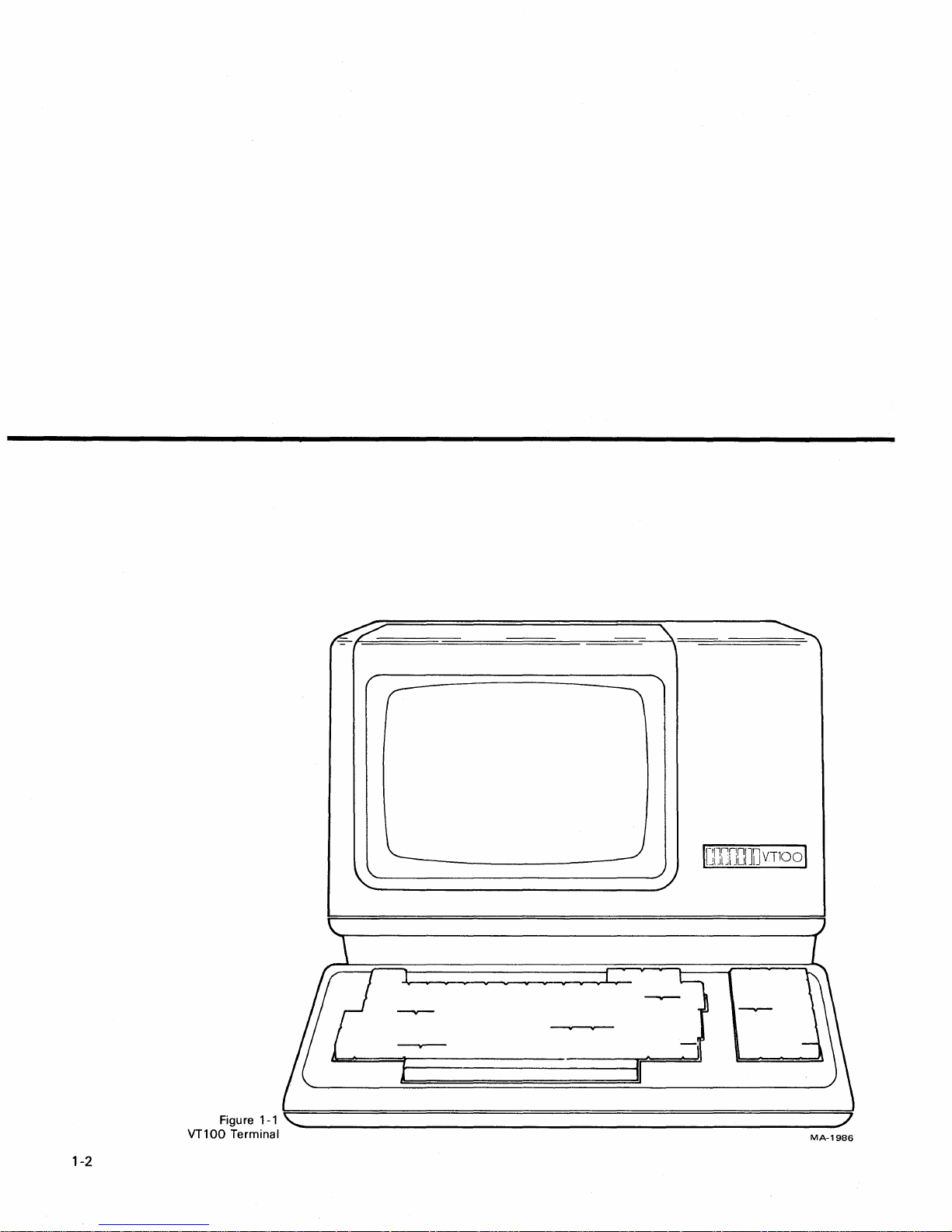
1-2
MA-1986
The
VT100
typewriter
computer.
CHAPTER
OPERATOR
is
a simple device
that
uses a video screen instead
If
you can operate a typewriter, you can operate a VT100.
to
operate. The terminal (Figure 1-1)
of
paper and communicates
INFORMATION
is
basically a
with
1
a
Chapter 1
is
divided
1.
Controls and Indicators
2. Setup Mode
3. Definition
Self- Testing the
4.
5.
What
Part 1 shows all the controls and indicators on the terminal and summarizes
the function
Part 2 defines the
Part 3 describes each feature in
further information on a feature mentioned in the
in Part 2.
Part 4 provides information on
required
the
tests have been
Part 5 provides a procedure
with
the VT100. Easily recognized failures
provided
into
five parts:
of
Each
Setup Feature
VT100
to
do
in
the Event
of
each, thus providing a quick reference for these functions.
SET-UP mode and briefly summarizes its features.
to
start the built-in self-tests and
ru
n.
for
each symptom. Check this Jist before calling
of
a Problem
detail. Refer
self-testing the VT100. It outlines the steps
to
follow
in case you encounter any problem
to
this section
SET-UP Summary provided
how
to
interpret the results once
with
simple corrective actions are
for
service.
if
you need
1-3
OPERATOR
INFORMATION
PART
The
a computer - information entered through the keyboard is sent
is simultaneously an
the
dicators on
1 -
KEYBOARD
VT100
computer is displayed on the video screen. The
terminal normally performs a
the
VT100
ET-UP
D
CLEAR
SETI
GDJ[!][XJrnrnGJ[IJwrnrnEJmo
GG000000~G0wwnB
~@000G0~00~~.~Dc:::JgJ
§;]I
'"'''
10000000[J[]ITJG@J
CONTROLS
output
CLEAR
TAB
device for the computer -
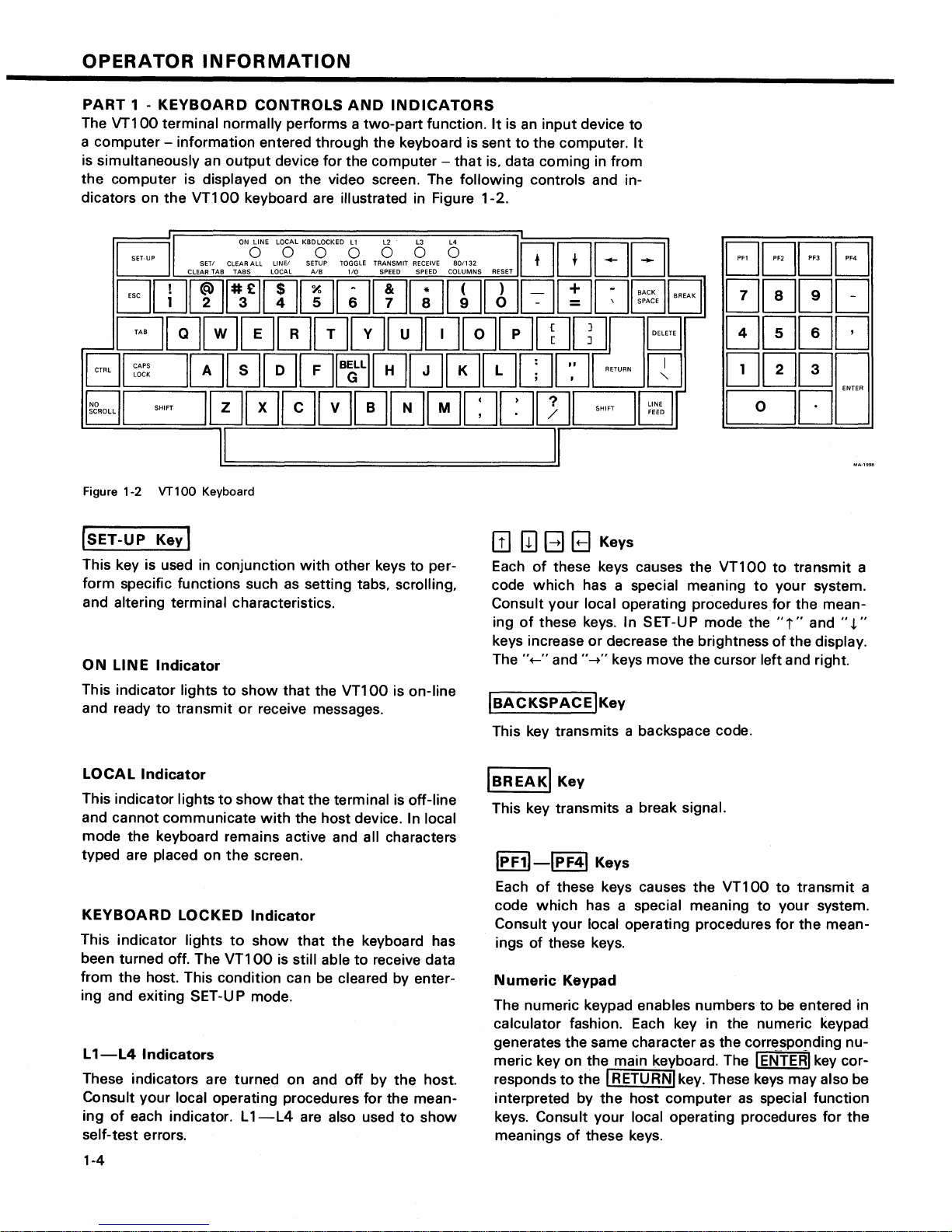
keyboard are illustrated in Figure 1-2.
ONONE
LOLKBDOCKED
ALL
LlNEI
TABS
LOCAL
AND
two-part
0 0 0 0
SETUP
TOGGLE
AlB
110
INDICATORS
function.
TRANSMIT
RECEIVE
SPEED SPEED COLUMNS
It
is
an
input
to
the computer.
that
is, data coming in from
following
801132
controls and in-
~~BB
T'
RESET
device to
It
--
[JF1
[JF2
~
~~;~E
EJ
000[J
[JF3 [JF4
0000
~000
0DD
I I
Figure 1-2 VT100 Keyboard
(SET-UP
This key is used
form specific functions such
and altering terminal characteristics.
ON
This indicator lights
and ready
LINE
Key I
in
Indicator
to
transmit
conjunction
as
to
show
that
or
receive messages.
with
other keys to per-
setting tabs, scrolling,
the VT100 is on-line
[!]
[II
B B Keys
Each
of
these keys causes the
code
which
Consult your local operating
ing
of
keys increase
The ''+-'' and
IBACKSPACE
This key transmits a backspace code.
has a special meaning
these keys. In SET-UP mode the
or
decrease the brightness
"-+"
keys move the cursor left and right.
IKey
VT100
proceduresfor
to
transmit
to
your system.
the mean-
"i"
and
of
the display.
a
",t."
LOCAL
This indicator lights
and cannot communicate
mode the keyboard remains active and all characters
typed are
KEYBOARD
This indicator lights
been turned off. The
from the host. This condition can be
ing and exiting SET-U P mode.
L
1-L4
These indicators are turned on and
Consult
ing
self-test errors.
1-4
Indicator
placed on
LOCKED
Indicators
your
local operating procedures for the mean-
of
each indicator. L
to
show
the
Indicator
to
VT100
1-L4
that
the terminal is off-line
with
the host device. In local
screen.
show
that
is still able
are also used
the
keyboard has
to
receive data
cleared by enter-
off
by
the
host.
to
show
IBREAKI
This key transmits a break signal.
IPF11-lpF41
Each
code
Consult
ings
Numeric
The numeric keypad enables numbers to be entered in
calculator fashion. Each key in the numeric keypad
generates the same character as the corresponding
meric key on the main keyboard. The I
responds
interpreted by
keys.
meanings
Key
Keys
of
these keys causes the
which
of
Consult your local operating procedures for
has a special meaning
your
local operating procedures for the mean-
these keys.
Keypad
to
the I RETURNI key. These keys may also be
the
host
computer
of
these keys.
VT100
to
to
your system.
ENTERI
as
special function
transmit
key cor-
a
nu-
the
I DELETEI
This key causes the
ter
code
or
may not be erased from the screen.
IRETURNI
This transmits either a carriage return
carriage return
SET-UP
I
LIN
This key transmits a linefeed code.
Key
to
the host system. The deleted character may
Key
(CR) and linefeed (LF) code. This
selectable feature.
EFEEDI
Key
VT100
to
transmit
a delete charac-
(CR)
code
or
is
SET-UP
When the terminal is in
switches the
from SET-UP B
a
LIN
a
In SET-UP mode this key switches the
municate
VT100
CAL).
Al8
E/LOCAL
with
from
~
Key
terminal from SET-UP A
to
SET-UP
~
Key
your system (ON
communicating
SET
-U P mode
A.
with
this
to
SET-UP B
VT100
LI
N
E)
your system (LO-
to
or
stops the
com-
key
or
ISHIFTI
When pressed, this key enables the uppercase function
of
tion
RESET~
When the terminal is in SET-UP mode this key starts
the reset sequence. This has the same
the
80/132
When the
switches
ters per
RECEIVE SPEED Q
When the terminal is in SET-UP B mode
the
ascending order.
Key
all keys.
the SHIFT key
terminal
terminal through
If
a key does
Key
power
COLUMNSr;]
terminal
the
display line size from
line
or
from
not
have an uppercase func-
will
be
disregarded.
result as turning
off
and then on.
Key
is
in SET-UP A mode this key
80
to
132
132
to
80
characters per line.
Key
this
the
receive baud rate settings in
charac-
key steps
CLEAR
In
the
SET/CLEAR
In
tal tabs.
ICAPSI
LOCK
This key enables
betic characters only. All numeric and special symbol
keys remain in lowercase.
I~~ROLLI
When
data from the
second time, transmission resumes from where
stopped. Check your local operating procedures
sure
ALL
TABS
SET
-U P A
VT100.
SET-UP A this key sets
Key
Key
first pressed, this key stops the transmission
that
your system recognizes
l!J
Key
this
key clears all horizontal tabs set in
TA8
~
Key
or
clears individual horizon-
the
transmission
computer
to
the VT100.
of
uppercase alpha-
When
this
key.
of
pressed a
it
was
to
en-
I#£l
TRANSMIT
When
the
terminal through the
ascending order.
TOGGLE
When
the
selected operational feature on or off.
When pressed in combination
key causes a bell code
SPEED
the terminal is in
1/0
the terminal is in SET-UP B mode
Key
~
~
Key
Key
SET
-U P B mode
transmit
to
be sent
baud rate settings in
with
to
this
key steps
this
key
the CTRL key
the
host.
turns
this
ICTRLI
When
causes the
cial meaning
ITABI
This key transmits a
I
Esci
This key transmits a code
meaning
your
mand.
Key
pressed in combination
VT100
Key
Key
to
system
to
transmit
to
your
system.
tab
your system. In
to
treat
the
with
another key, CTRL
a code
code.
which
many
next keys pressed as a
which
has a spe-
normally has a special
applications,
it
tells
com-
1-5
OPERATOR
INFORMATION
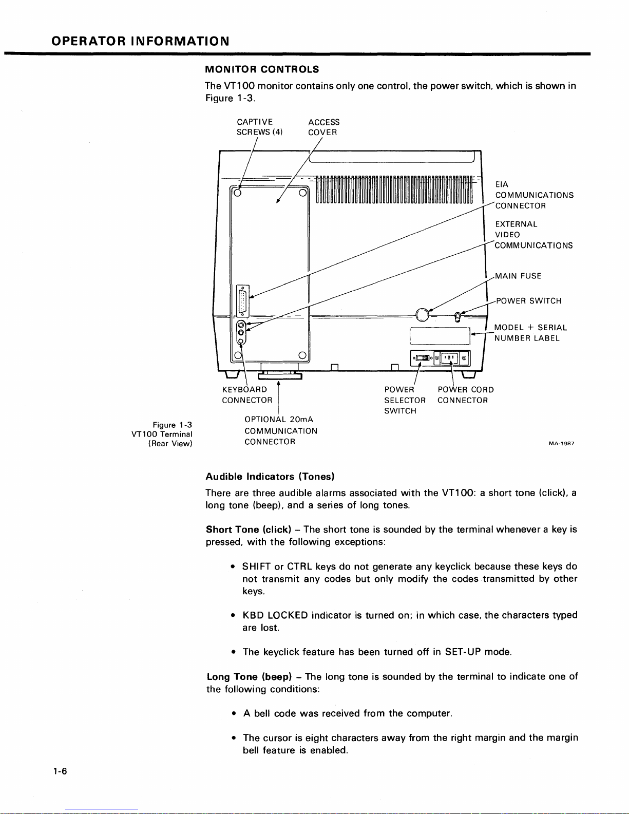
MONITOR
The
VT100
Figure 1-3.
CAPTIVE
SCREWS (4)
l
d
-r-r,
__
CONTROLS
monitor
contains
ACCESS
COVER
only
one control. the
~~~~~~~~~---
~===n~
__
~~
______
power
I
I
~
__
~o~ol@I~~
switch,
~/NUMBER
which
EIA
COMMUNICATIONS
CONNECTOR
EXTERNAL
VIDEO
COMMUNICATIONS
MAIN
POWER SWITCH
"\
MODEL
is
shown
FUSE
+ SERIAL
LABEL
in
VT1
00
(Rear View)
Figure
Terminal
KEYBOARD I POWER POWER CORD
CONNECTOR
1-3
Audible
There are three audible alarms associated
long tone (beep), and a series
Short
pressed,
Long
the
OPTIONAL
COMMUNICATION
CONNECTOR
Indicators
Tone
with
• SHIFT
not
keys.
• KBD LOCKED indicator
are lost.
• The keycJick feature has been turned
Tone
following
20mA
(Tones)
(click)
transmit
(beep) - The long tone is sounded by
- The short tone
the
following
or
CTRL keys
any codes
conditions:
exceptions:
do
SELECTOR CONNECTOR
SWITCH
with
the
VT100:
of
long tones.
is
sounded by the terminal whenever a key is
not
generate any keycJick because these keys
but
only modify
is
turned on; in
the
which
off
in SET-UP mode.
the
a short tone (click), a
codes transmitted by
case, the characters typed
terminal
to
MA-1987
other
indicate one
do
of
1-6
• A bell code
• The cursor is
bell feature
was
eight
is
enabled.
received
characters
from
the computer.
away
from the right margin and
the
margin
Series
rapid succession
reading
of
or
Long
writing
Tones
to
indicate
the
- The terminal
SET-UP features. (When this occurs, check
features and then perform the
will
sound the long tone several
that
the nonvolatile memory (NVR) had
Recall or Save operation again.)
times
difficulty
the
SET-UP
in
in
SET-UP
PART
MODE
2
Unlike
turn
memory
switch
The
mode
of
then change the features and store any
most
terminals,
the built-in terminal features on or off. Instead,
(NVR)
which
the
VT100
does
always remembers
not
use switches
what
features have been selected, as
the
or
VT100
had been set.
selection and storage
of
operation called SET-UP mode. When you enter SET-UP mode,
the features stored in the temporary memory
of
built-in terminal features
new
feature selections either temporarily,
is
shown
is
jumpers
to
individually
uses a nonvolatile
performed in a special
the
on the screen. You can
by leaving SET-UP mode; or on a fixed basis, by performing a Save operation. In
either case,
operation
OFF, all temporary feature settings are replaced by the features
the
terminal operation
is
performed, or the terminal is
will
reflect
reset
the
new
feature selection. If a recall
or the terminal power is turned
that
have been
stored on a fixed basis.
SET-UP
When entered, SET-UP mode provides
status. The first presentation - SET-UP A set in the
line. The second presentation - SET-UP B - summarizes the status
Features
at a Glance
terminal and a visual ruler
two
brief summaries
of
the current feature
displays the location
which
numbers each character position on
of
the
of
terminal features.
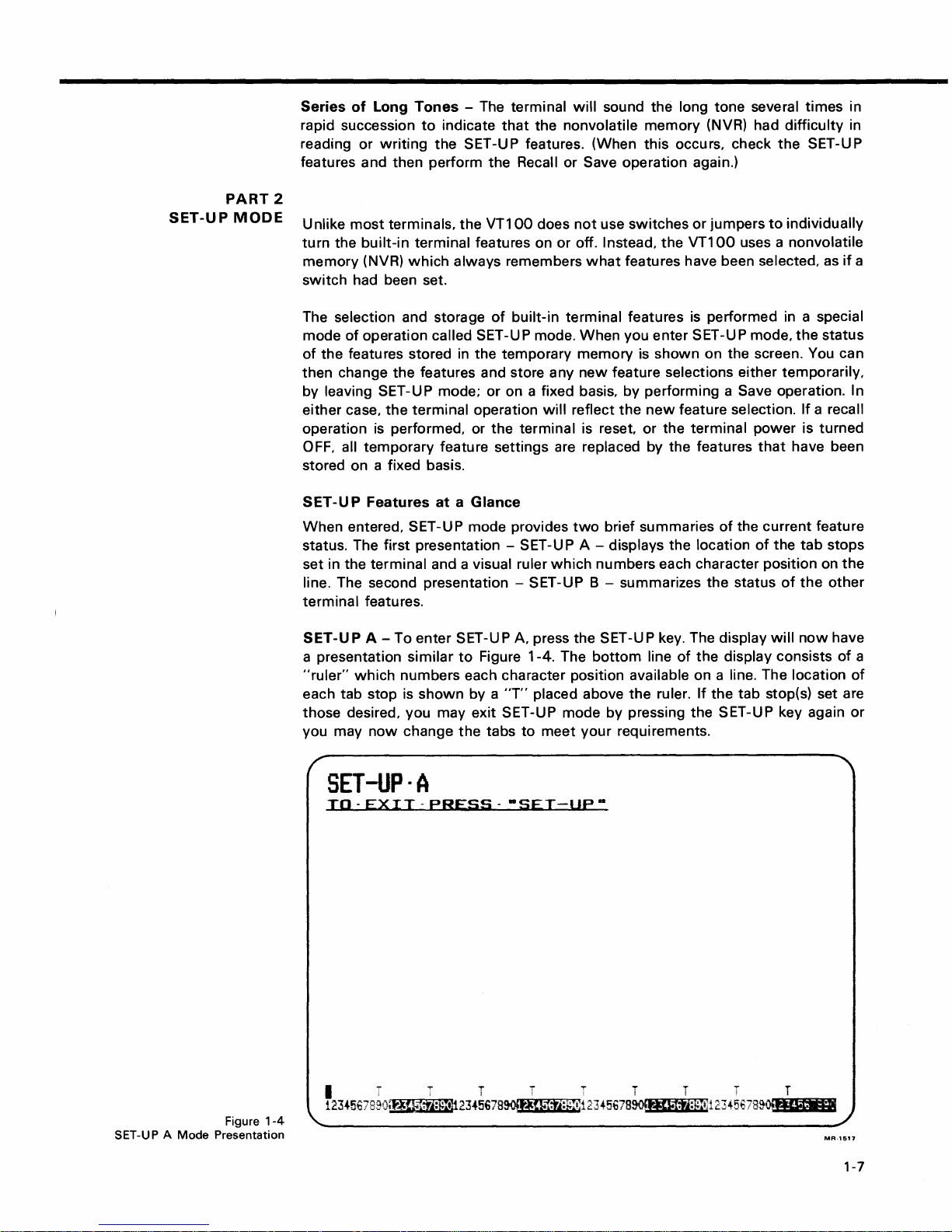
SET -U P A - To enter
a presentation
"ruler"
which
similar
numbers each character position available on a line. The location
each tab stop is
shown
SET
-U P A, press the
to
Figure 1-4. The
by a
"T"
SET
bottom
placed above
-U P key. The display
line
of
the
the
ruler. If the tab stop(s) set are
will
display consists
now
those desired, you may exit SET-UP mode by pressing the SET-UP key again
you may
now
change
the
tabs
to
meet
your
requirements.
tab
the
if
a
status
stops
the
other
have
of
a
of
or
Figure
SET-UP A
Mode
Presentation
1-4
SET-UP·A
TO-EXIT-PREss--SET-UP-
MR·1517
1-7
OPERATOR
INFORMATION
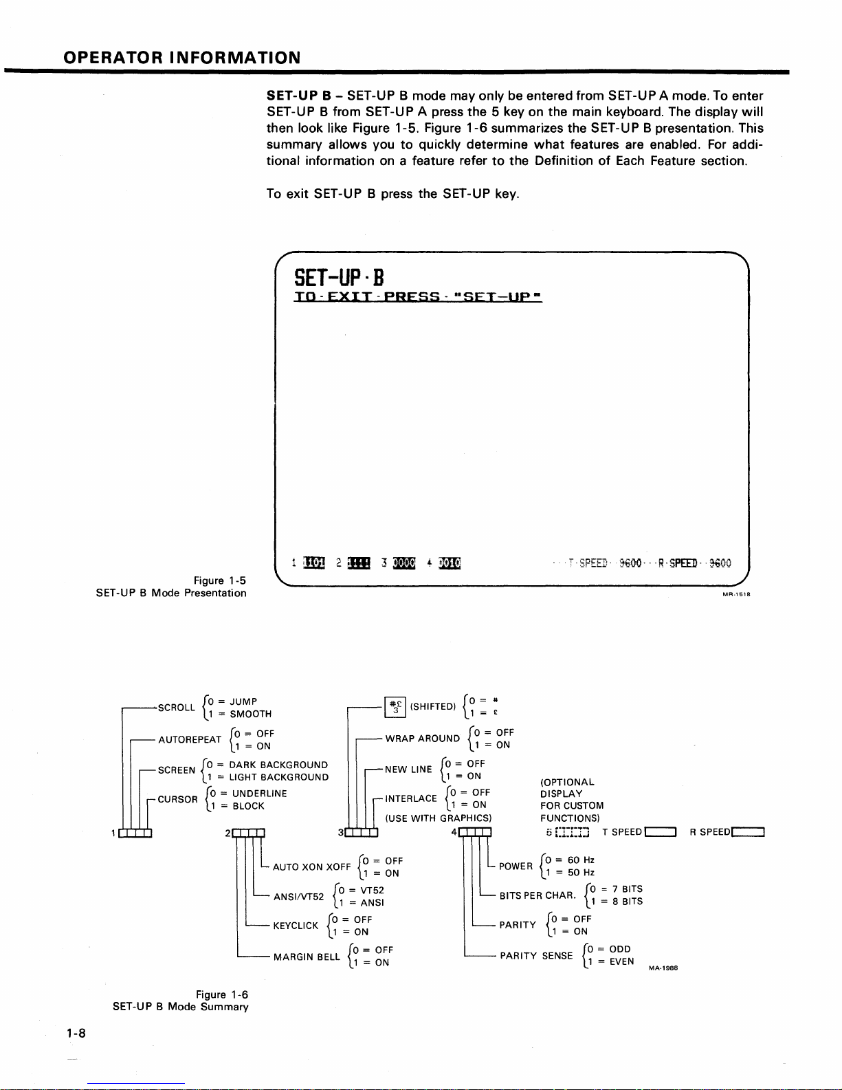
SET-UP B - SET-UP B mode may only be entered from SET-UP A mode. To enter
SET-UP B from SET-UP A press the 5 key on the main keyboard. The
then look like Figure 1-5. Figure
summary
tional information on a feature refer
To exit SET-UP B press the SET-UP key.
allows you
to
quickly determine
SET-Up·B
TO-EXIT-PRESS-"SET-Up·
display
1-6
summarizes the SET-U P B presentation. This
what
features are enabled.
to
the Definition
of
Each
Feature section.
For
will
addi-
Figure
SET-UP B Mode Presentation
SCROLL
AUTOREPEAT
SCREEN
1-5
[0 = JUMP
l1
= SMOOTH
[0
l.1
[0 =
DARK
L 1 = LIGHT BACKGROUND
CURSOR
[0
= UNDERLINE
l.1
= BLOCK
2 3
=
OFF
= ON
BACKGROUND
AUTO XON XOFF
ANSIIVT52
KEYCLICK
MARGIN
[0
L1
BELL
[0 =
l.1
=
= OFF
= ON
[0
l.1
~
(SHIFTED)
~
WRAP
AROUND
NEW LINE
INTERLACE
(USE WITH GRAPHICS)
[0
= OFF
L1
= ON
VT52
ANSI
= OFF
= ON
[0
l.1
[0
l.1
{a
= OFF
= ON
= OFF
= ON
4
= #
1 = £
{a
= OFF
1 = ON
POWER
PER
BITS
PARITY
PARITY
"SPEED'
(OPTIONAL
DISPLAY
FOR CUSTOM
FUNCTIONS)
5
[1:1:1:1
[0 = 60
\..1 = 50
SENSE
CHAR.
[0
= OFF
l.1
= ON
Hz
Hz
[0
l.1
[0 = ODD
l.1
1€OO--'R-SPEED-
T SPEED c:::::J R
= 7 BITS
= 8 BITS
= EVEN
MA-1988
·~oo
MR-1S1a
SPEEDc::::J
Figure
SET-UP B Mode Summary
1-6
1-8
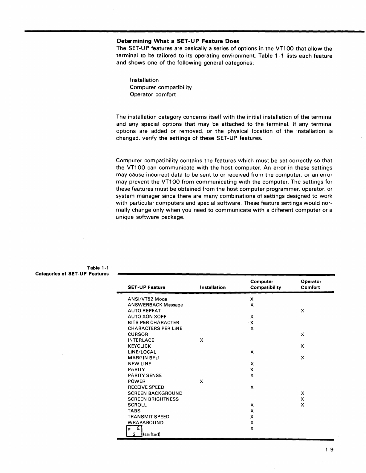
Determining
What
a SET -U P
Feature
Does
The SET-U P features are basically a series
terminal
and
to
shows
be
one
tailored
of
the
to
its operating environment. Table 1-1 lists each feature
following
general categories:
I nsta Ilation
Computer
Operator
compatibility
comfort
of
options in the
VT100
that
allow
the
Categories
of
SET-UP
Table 1-1
Features
The installation category concerns
and any special options
options
changed, verify
Computer
the
are added or removed,
the
compatibility
VT100
can communicate
may cause incorrect data
may
prevent
these features
the
must
VT100
that
settings
contains
to
from
be obtained
itself
may be attached
or
of
these SET-UP features.
the
with
the
be sent
to
communicating
from
system manager since there are many
with
particular
mally
unique
SET-UP
change only
software
computers
package.
Feature
when
and special software. These feature settings
you need
to
Installation
with
the
initial installation
to
the
physical location
features
which
host
computer. An error in these settings
or received from
with
the
host
computer
combinations
communicate
of
the
terminal
the
terminal.
must
be set correctly
the
If
any terminal
of
the
installation is
computer;
or
so
an
that
error
the computer. The settings for
programmer, operator, or
of
settings designed
with
a different
Computer
Compatibility
to
would
computer
Operator
Comfort
work
nor-
or a
ANSI/VT52
ANSWERBACK
AUTO REPEAT
AUTO XON XOFF
BITS
CHARACTERS
CURSOR
INTERLACE
KEYCLICK
LINE/LOCAL
MARGIN
NEW
PARITY
PARITY SENSE
POWER
RECEIVE SPEED
SCREEN
SCREEN
SCROLL
TABS
TRANSMIT
WRAPAROUND
E2]
3 (shifted)
Mode
PER
CHARACTER
BELL
LINE
BACKGROUND
BRIGHTNESS X
SPEED
Message
PER
LINE
X
X
X
X
X
X
X
X
X
X
X
X
X
X
X
X
X
X
X
X
X
X
X
1-9
OPERATOR
INFORMATION
The operator
comfort
category contains the SET-UP features designed exclusively
for the operator. These features
vidual
preference. These features do
terminal and the computer.
the
The next section, Definition
tion
of
each feature.
How
to
Change a
Changing any
performed by
1.
Enter SET-UP mode by pressing the SET-UP key.
2.
Select the appropriate SET -U P mode by pressing
SET-UP
or
all
of
following
keyboard each
from SET-UP B
of
Feature
the SET-UP features
the same basic steps.
time
to
SET-UP A.
3. Position the cursor above
To
position
TURN"
keys
the
cursor,
may
be used. Some features do
specific key is dedicated
4. Change the feature setting
or
the
keyboard
the
feature
appropriate dedicated key. Each
will
change, generally to the opposite state.
allow
the
operator
not
affect any operations
to
tailor
the
Each SET-UP Feature, describes
is
a simple operation and is generally
the
you
want
to
switch
the
feature
the
"SPACE"
to
changing the feature.
by
pressing either the 6 key on
from SET-UP A
switch
bar,
or
"+-",
tab
"-+",
not
use this step since a
time
VT100
that
the
to
fit
occur between
specific func-
5 key on the main
to
SET-UP B or
stop
to
be changed.
"TAB"
the
and "RE-
the
main
key is pressed
indi-
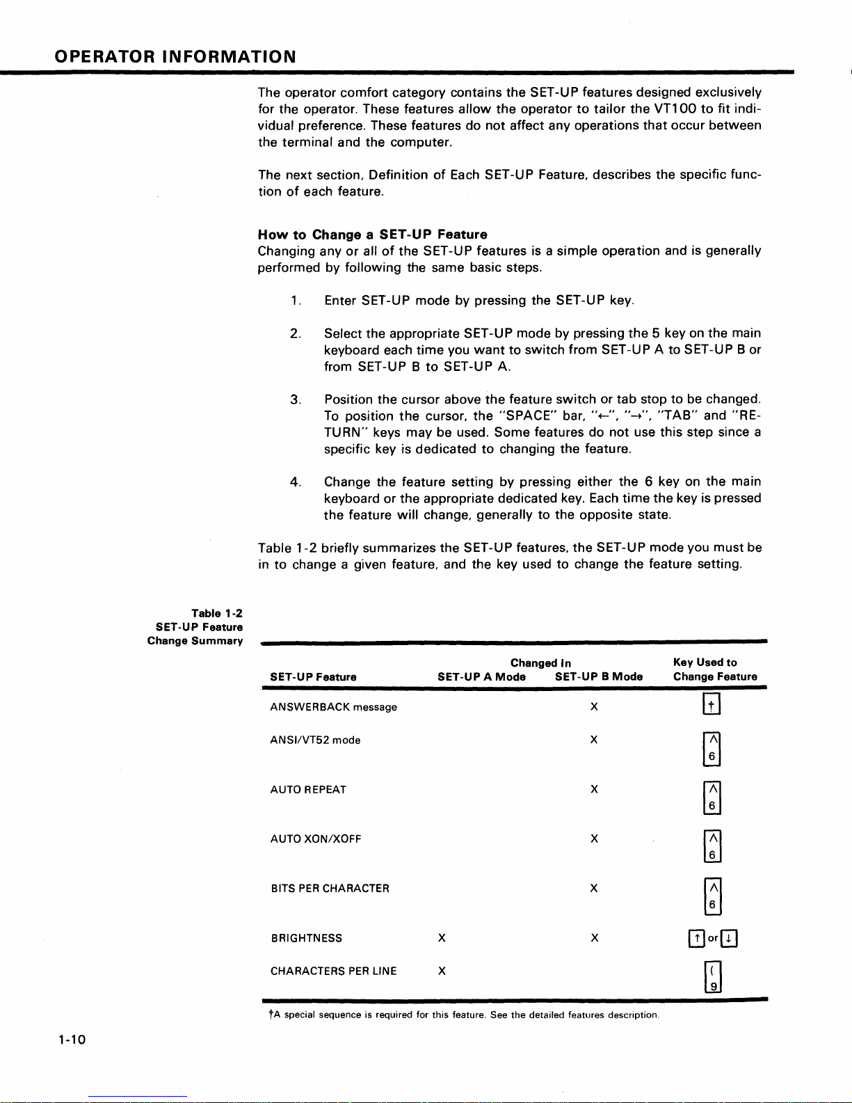
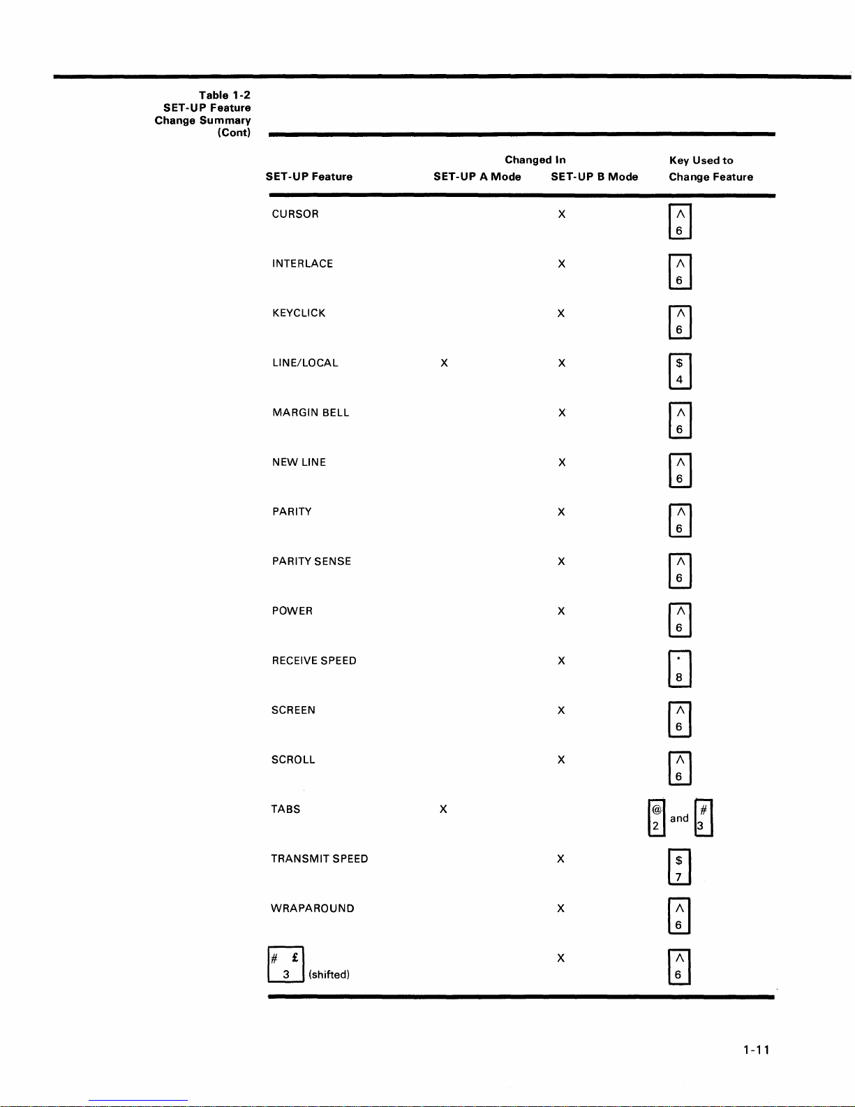
Table
SET-UP Feature
Change
Summary
1-2
Table
1-2
briefly summarizes the SET-UP features,
in
to
change a given feature, and the key used
SET-UP Feature
ANSWERBACK
ANSI/VT52
AUTO REPEAT
AUTO
XON/XOFF
BITS
PER
BRIGHTNESS x
message x
mode
CHARACTER x
SET-UP A
Changed
Mode
the
SET-UP mode you must be
to
change
In
SET-UP B
the
feature setting.
Mode
x
x
x
x
Key Used
Change Feature
to
CHARACTERS
tA
special sequence is required for
1-10
PER
LINE x
this
feature. See
the
detailed features description.
SET-UP
Change
Table
1-2
Feature
Summary
(Cont)
SET-UP
Feature
CURSOR
INTERLACE
KEYCLICK
LINE/LOCAL
MARGIN
NEW
PARITY
PARITY SENSE
BELL
LINE
Changed
SET-UP A Mode
X X
In
SET-UP B Mode
X
X
X
X
X
X
X
Key
Used
to
Change Feature
~
~
~
[TI
[J
~
~
[]
POWER
RECEIVE SPEED
SCREEN
SCROLL
TABS
TRANSMIT
WRAPAROUND
3 (shifted)
EJ
SPEED X
X
~
X
GJ
X
~
X
~
X
~and~
m
X
m
X
[]
1-11
OPERATOR
INFORMATION
Setting
Setting
the
Answerback
the
answerback message is
Message
different
from
features. An answerback message can be typed
ing steps:
1.
Place
the
terminal
2. Press the I SHI FTI and
spond by placing
I CAPS LOCKI key
3. Type the message
used in
ter
typing
again and
is
the
actual
not
a part
the
answerback
go
in SET-UP B mode.
[!]
A=
on
the
will
not
delimiter
answerback
of
the
answerback message.
message. type the message
back
to
step 2. This is the
keys simultaneously. The
screen. (The ISHI FT' key IS required. The
work
here.)
character
message. The message
answerback message.
4. Type
the
answerback
message. The message
ters. including space and control characters. Control characters
displayed as a • character
5.
Type the message
character is
typed
delimiter
the
to
indicate
character. Once the messsage
answerback
screen.
setting
into
the
which
only
way
their
presence in
message
any
of
the
other
VT100.
using
terminal
may
be any character
delimiter
If
a mistake is made
delimiter
to
correct errors in
may
be up
to
the
will
disappear
terminal
the
follow-
will
charac-
when
character
20
charac-
will
message.
delimiter
from
re-
not
the
be
the
The save
performed
keyboard. The
not
though
modify
VT100
perform
it
the
features.
operation
at
this operation, al-
can
the
computer
temporarily
setting
NOTE
must
be
terminal
can-
of
the
Once
the
above steps have been
porarily stored in
Saving
SET-UP
SET-UP features
basis. To
the
formed.
temporarily
terminal
or
the
Features
now
terminal
the
VT100
may
be changed and stored on
store a feature.
reacts
according
is reset.
feature settings are replaced
To
store SET-UP
a simple operation
1.
2. Press
feature
that
Place
the
terminal
the
ISHIFTI and
the message
brief
wait.
the
settings
is
"Wait"
terminal
completed
and can be saved
exit
to
the
or
the
terminal
by
the
features
on a fixed basis.
accomplished
in SET-UP mode.
rm
keys simultaneously. The screen
will
be displayed in
will
return
the
answerback
with
either a temporary
SET-UP
new
mode
setting.
power
that
have been stored on a fixed basis.
perform
by performing
the
to
SET-UP A mode.
the
after
If
is
Once these steps have been performed. SET-UP features
rarily stored
Recalling
The
temporarily
have been stored
perform
will
now
be
stored
SET -U P
Features
stored SET-U P feature settings may
on
a fixed basis.
the
recall operation as follows:
on a fixed basis.
If
you
wish
to
differ
return
message
will
be
tem-
Save operation.
or a fixed
changing
the
feature;
a recall operation is per-
turned
off. all
temporary
a save operation. This
the
following
upper-left
which
from
to
the
steps:
will
clear and
corner.
had been
the
settings
fixed settings.
After
tempo-
which
is
a
1-12
1.
Place the
terminal
in SET-UP mode.
When a
performed
screen are destroyed.
recall
the
operation
contents
NOTE
is
of
the
2.
Press
the
After a brief
the
ISHIFTland
message
"Wait"
wait
the
[B]
keys simultaneously. The screen
will
appear in
terminal
will
the
upper-left
return
to
SET-UP A mode.
corner
will
of
the
clear and
screen.
When a
formed
screen are destroyed.
PART
DEFINITION
reset
operation
the
contents
3
OF EACH
NOTE
is
per-
of
the
SET-UP
Resetting
The
nal
memory
switch
FEATURE
the
VT100
may
had been
1.
Place
2. Press
power
the
Terminal
be reset
is cleared and the self-test
turned
the
the
on self-test
fixed SET-UP features.
This section describes each SET -U P feature in detail (in
alphabetical order) and states
the
terminal.
NOTE
Unless
ing
the screen.
will
ANSI
VT52
previous
programmer's
ANSWERBACK
Answerback
the
The
with
sage
takes place
or
may
AUTO
otherwise
features does
ANSI/VT52
The
VT100
ming
standards -
stitute
(ANSI) and VT52. In
stated,
not
Mode
terminal
generate and respond
standards
mode,
the
DIGITAL
minal. Both
ANSI
section
is a
question
host
computer
VT100
answerback feature provides
the capability
to
the
host. The entire answerback sequence
automatically
requiring
also be
operator
transmitted
REPEAT
entering
result
follows
American
X3.41-1974
VT100
software
and
VT52
of
Message
asks
to
identify
action. The
The auto repeat feature
ically repeated
second
half
when
second. The auto repeat feature
board keys
SET-UP
ESC
NO SCROLL
at
the
except
the
key
the
rate
is
following:
TAB
RETURN
CTRL and
how
in the loss
ANSI
to
terminal
using the
modes are
this
manual.
and
answer
the
terminal
itself
without
by
typing
allows
of
about
held
down
each feature
SET-UP
of
two
different
National
mode, the
mode
data
Standards
affects
and
chang-
displayed
program-
VT100
coded sequences per
and
X3.64-1977.
is
compatible
VT52
outlined
sequence
to
identify
the
with
video
in
where
itself.
terminal
by sending a mes-
affecting
answerback
the
mesage
screen
CTRL-BREAK.
a key
to
be
automat-
30
characters per
for
more
than
one-
any
affects
key
all key-
on
In-
ter-
the
from
the keyboard.
When
program
OFF and
terminal
0 key on
AUTO
The
chronizing codes
then
back ON. To reset
in SET-UP mode.
the
main keyboard. The
will
be run, and
XON/XOFF
VT100
is capable
the
XON (DC1) and XOFF (DC3). The
XOFF control sequence is used
sion
of
data
from
the
XON sequence is used
the feature enabled,
code
when
one
1.
The internal
of
the
the
2. The NO SCROLL key is pressed
When
pressed again,
mode,
In
the
puter
If
the
3. The
4.
the
or
XO
N code
to
host
terminal
CTR
L-S is pressed.
buffer
empties,
the
terminal
CTRL-Q is pressed, the
to
resu me transmission
the
terminal.
computer
XON/XOFF codes, data sent during
tions,
or
when
the
terminal
lost.
NOTE
The
VTT
00
will
(DC3) code is
an
XON
XON/XOFF
(DC1) code is received regardless
BITS PER
This feature
either 7 - or
ation,
bit
mitted
and is ignored for a
CHARACTERS
The
VT100
characters
the screen is
the
132
characters
is equipped
always
received
feature
setting.
CHARACTER
allows
8 is set
8-bit
the
characters.
to
PER LINE
is capable
per
line.
In
80
characters
character
wide
with
by
per
14
the
and
a space (or
Advanced
the
terminal
is run as
VT100
terminal
of
automatically
computer
to
resume transmission.
VT100
following
buffer
is reset,
if
the
the
terminal:
will
will
react according
to
stop
to
the
will
generate the XOFF
events occur:
is nearly full
is placed in SET-UP
the
I NO SCRO LLl key
is taken
VT100
software
does
buffer
is in SET-UP mode,
stop
transmission
will
resume transmission
terminal
of
the
line mode,
lines high
to
transmit
When
set
0)
for
characters trans-
II
characters received.
displaying either
80
character per line mode,
wide
by
24
the
(24
lines
Video Option). In
the
termi-
terminal
power
be reset,
generating syn-
the
transmis-
terminal;
With
mode
out
of
SET -U P
will
transmit
from
the
com-
not
support
full condi-
may
when
an
XOFF
of
when
the A UTa
and receive
for
8-bit
oper-
80
or
132
lines high. In
screen is
if
the
132
VT100
the
1-13
the
to
the
is
the
be
OPERATOR
132
character
physically
line
NOTE
When
vice-versa, the
mode
changing
the
but
current
INFORMATION
per
line
same
width
the
characters are
from
80
to
contents
mode,
as in
132
the
character
of
displayed lines
the
80
character
more
compact.
per
line
the screen are lost.
mode
are
per
or
When
key
generates
terminal
NOTE
If
double
since
the
the
new
only
to
perform a line
line
feeds
computer
line
occur
is
feature
the
CR
consistently,
already
is disabled,
code;
an
feed only.
performing
the
LF
code causes
turn
this
this
function.
RETURN
feature
the
off
CURSOR
The
VT100
indicate
acter
displayed
ing
block
ditional
definition
the
will
(.).
function;
offers a
"active
be
placed
as
either a blinking
The
in
Chapter
INTERLACE
This
feature
is used
interlace feature
is
not
installed.
KEYCLICK
The
keyclick
TONE
is a
key is pressed. The
suit
the
operator's
rience has
when
Like
there
the
shown
is an
bell tone,
able.
LINE/LOCAL
The
LINE/LOCAL
the
place
(off-line)
keyboard
typed
puter
on
the
LOCAL
connected
to
or
on
the
MARGIN
The
a
typewriter.
end
a
tone
terminal
condition.
ON-LINE
on
the
keyboard are
and messages
screen. In
indicator
from
received
from
keyboard are
BELL
margin
of
bell
the
current
to a lert
If
the
the
the
feature
choice
positions"
on
cursor
see
3.
for
should
tone
which
keyclick
needs.
that
audible
the
feature
in
either
When
indicator
from
the
LOCAL
is ON),
computer;
the
echoed
cursor
line
while
operator.
of
or
the
screen. The
underline
selection
the
SGR escape sequence
high
resolution options. The
be
turned
is
generated
may
However,
an
operator
feedback
keyclick
allows
an
the
terminal
is ON) all
sent
the
computer
condition
the
terminal
computer;
on
is
much
is
eight
typing,
two
cursor
where
displays
the
cursor
(-)
may
perform
off
if
such an
every
be
turned
on
research and
is
more
from
the
keyboard.
volume
the
ON-LINE
directly
is
not
operator
or a LOCAL
is
on-line
to
are
(the keyboard
is
electrically
messages are
and characters
the
the
screen
same
directly.
as
characters
the
VT100
to
next
char-
may
be
or a blink-
an
ad-
option
time
or
off
to
expe-
accurate
adjust-
to
easily
(the
characters
the
com-
displayed
dis-
not
sent
typed
the
bell
in
from
the
sounds
PARITY
Parity,
sion.
tect
checkerboard
the
determines
disabled,
a
when
enabled,
If a transmission
it
and
character
if
the
no
parity
PARITY
the
methods
by
parity
puter
match,
parity
the
VT100.
sense
is sending.
most
SENSE
sense feature
of
parity
must
characters
rejected even
rectly
by
the
VT100.
the
checkerboard
screen in place
checks
error
indicate
character
with
the
parity
bit
its
(::::::
error. The
is even
is
transmitted
checking,
If
the
parity
be
matched
If
the
parity
sent
though
the
If a parity
character ( :::::: ) will
of
the
received character.
for
occurs,
presence
) on
defines
odd
feature
character
NOTE
If
the
parity
will
be
disregarded.
feature
is
turned
off, the
POWER
During
be
set
set
to
the
to
60
initial
the
hertz.
installation,
power
line
frequency. In
the
RECEIVE SPEED
The receive speed
transmit
anyone
speed. The
of
the
110,134.5,150,200,300,600,1200,1800,2000,
2400,
3600,
The receive speed is
speed;
transmit
the
data
terminal
must
be
VT100
following
4800,
9600,
independent
may
at a different
set
is capable
preselected
19,200
receive
speed.
correct
the
data
VT100
by
the
screen in place
parity
sense
or
odd.
When
or
received.
which
or
even, is
is on,
the
to
the
parity
sense features
to
the
computer
was
received
incompatibility
be
shown
parity
sense
terminal
the
to
match
the
of
speeds:
baud.
of
the
data
at
one
transmis-
can
placing
feature
parity
of
the
being
terminal's
the
do
will
occurs,
on
selection
display
U.S.
this
computer
receiving
50,
transmit
speed
de-
a
of
is
two
used
com-
not
be
cor-
the
must
is
at
75,
and
NEW
LINE
The
new
line
feature
terminal
typewriter.
pressing
turn
(CR)
to
function
When
the
and
RETURN
code is received,
enables
like
the
the
new
key
line
feed (LF) codes.
the
code
the
RETURN key
RETURN key on an
line
feature
generates
is
interpreted
return and line feed.
1-14
the
When
on
electric
is enabled,
carriage re-
a line feed
as a
carriage
the
SCREEN
The screen
the
operator
screen. In
tains
light
verse
characters
screen
BACKGROUND
background
to
determine
the
normal
characters
mode,
on a light
feature
screen
on a dark
the
background.
of
the
the
background
mode,
the
background;
display
VT100
display
in
contains
allows
of
the
con-
the
re-
dark
SCREEN
Unlike
tain
stead, the
brightness. This feature
of
mechanical controls and still
select
comfort
may
BRIGHTNESS
most
video terminals,
switches
the
or
knobs
VT100
desired level
under
varied
electronically
be saved like any
to
eliminates
of
lighting
other
SCROLL
Scrolling is
isting lines on the screen
the
bottom
two
ways:
mode,
computer
the
or
jump
new
lines appear
sends
upward
top
of
scroll
them
the
or
to
screen.
or
smooth
on
to
baud rates, the data is very
rapid
upward
mode, a
of
data
ment
of
the
data
NOTE
Smooth
per
second
feature
puter
to ensure
mode
is enabled.
must
movement
limit
is placed on
may
be sent
lines occurs
to
be read as
scroll
mode
to
be
added
be
enabled
that
of
the
to
the
at a smooth
it
appears on
allows a maximum
to
the
and
data
is
TABS
Just
like a
typewriter,
preselected
points
individually changed,
the
on a line. These
or
totally
the
VT100
adjust
screen brightness. In-
does
controls
the
high failure rate
allows
the
brightness for
conditions. This
feature in
downward
make
It
the
movement
room
for
new
can be performed in
scroll. In
the
screen as fast as
the terminal.
difficult
the
lines. In
speed
terminal. The
At
to
read due
at
which
upward
smooth
steady rate
the
screen.
of
when
can
tab
six lines
Auto
by
the
smooth
jump
stops
screen. The
supported
not
lost
VT100
cleared and then reset.
not
con-
the screen
operator
to
maximum
setting
terminal.
of
ex-
lines
at
jump
scroll
the
the
higher
to
the
scroll
new
lines
move-
allowing
of
data
XON/XOFF
host
com-
scroll
or
tab
to
may
be
TRANSMIT
Transmit
receive speed. The
anyone
speed
of
the
SPEED
must
VT100
following
be set
to
is capable
preselected
match
of
transmit
the
computer
transmitting
speeds:
50,75,110,134.5,150,200,300,600,1200,1800,
2000, 2400,
Transmit
terminal
data at a
3600,
speed is
may
transmit
different
4800,
9600,
independent
data
at
speed.
and
19,200
of
receive speed;
baud.
the
one speed and receive
WRAPAROUND
When
this
feature is enabled,
the
81
st
or
133rd
character (depending upon the line size selected) inserted
on a line is
position
not
enabled, the
lowing
character position
automatically
of
the next line.
characters
81
st
would
of
or
the
placed in
If
the
wraparound
133rd
be
overwritten
current
the
first
character
feature
was
character and all fol-
into
the
last
line.
ri£l
L.!J (shifted)
The
VT100
United
acter sets is one character,
the standard U.S. character
percase 3 key on
character. The £ character is displayed
character set is selected.
contains character sets for
Kingdom. The difference
the # or
set
the
main keyboard displays the #
the
between
£ symbol.
is selected,
U.S. and
the
when
two
the
the
the
char-
When
up-
U.
K.
at
PART
4
SELF-TESTING
THE
VT100
A
self-test
the condition
checks the
mode
is
of
the
following
built
Advanced Video M
Nonvolatile
Internal
Memory
memory
Keyboard
This
test
is performed
Self-Test Error Codes
There are
Fatal errors cause
information
random
characters)
LEOs, L
guaranteed
two
broad categories
is displayed on
pattern
1-L4;
of
is
a possible error code displayed on
however,
if
a fatal
the
characters. The
into
the
terminal
should a
items:
emory
(NVR)
automatically
terminal
the
screen; however,
no
terminal
error
is found.
VT100
(if
of
to
that
automatically,
fault
be suspected. The
option
is installed)
whenever
the
terminal
errors: fatal and nonfatal.
immediately
stop all operations. No
the
only
error indication (in
function,
including
or
is
screen
most
addition
the
programmable
the
on
command,
self-test
turned
likely
to
lighting
tests
program
on.
intelligible
contains
the random
keyboard
of
LEOs, is
1-15
a

OPERATOR
INFORMATION
The
loopback
formed
be
invoked
the
proper
See the
for
further
test.
test
on
power-up;
programmer's
information
Nonfatal
is
separately
escape sequence.
Error
NOTE
not
per-
it
must
with
section
on
this
Table
1-3
Displayed
Codes
Nonfatal errors
LOCAL
the
mode
screen.
There are
1.
2.
3. Keyboard missing
do
not
halt
the
terminal
and an error code character is displayed in the
four
types
of
nonfatal errors:
Advanced Video
Nonvolatile
data
Option
RAM
or
malfunction
4. Data loopback error (Data)
Table
1-3
shows
the
possible
nonfatal
screen and the failure represented
Displayed
Character
AVO
Faulty
NVR
Module
KBD
Data
processor. Instead, the
data
RAM
(AVO)
checksum
error (NVR)
(KBD)
error
characters
by
each character.
that
terminal
upper-left
may
appear on
is forced
corner
to
of
the
1
2
3 X
4
5 X X
6
7
8
9 X
X
X
X
X X
X X
X
X
X
X
<
X
>
PART
If
procedure. This
some
If
items
it
appears
other
the
terminal
an
5 -
operator
WHAT
that
part
X X
X X X
TO DO
there is a problem in the terminal, you should
test
will
of
the
appears
can check
X
X
X
X
X
X
X
X
X
X
X
IN
THE EVENT OF A
help
to
determine
computer
to
be faulty, refer
prior
system.
to
making
PROBLEM
if
the
problem lies in
to
Table 1-4. This
a service call.
initiate
your
table
the
self-test
terminal
describes
or
in
the
1-16
Table
1-4
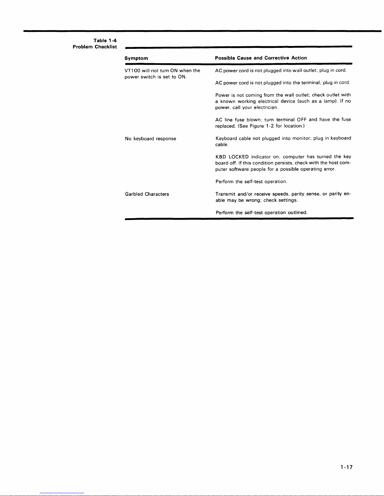
Problem Checklist
Symptom
VT1
00
will
not
turn ON
power
switch
is set
No
keyboard response
Garbled Characters
to
when
ON.
the
Possible Cause and Corrective Action
AC
power
cord is
not
plugged
AC
power
cord is
not
plugged
Power is
a
power.
AC line fuse
replaced. (See Figure
Keyboard cable
cable.
KBD LOCKED indicator on;
board off.
puter
Perform the self-test operation.
Transmit
able
Perform
not
known
coming from
working
call your electrician.
blown;
If
this condition persists. check
software
and/or
may
be
wrong;
the
self-test operation outlined.
electrical device (such as a lamp).
not
plugged into
people for a possible operating error.
receive speeds. parity sense.
check settings.
the
turn
terminal 0
1-2
for location.)
into
wall
into
the
wall
outlet;
monitor;
computer
terminal;
FF
outlet; plug in cord.
plug in cord.
check
outlet
with
If
and have the fuse
plug in keyboard
has turned the key
with
the host
or
parity en-
com-
no
1-17

 Loading...