

Page 1

InstallingandUsing
theVR320ColorMonitor
Order Number EK-VR320-IN-001
digital equipment corporation
maynard, massachusetts
Page 2

First Edition, January 1990
The information in this document is subject to change without notice and should not
be construed as a commitment by Digital Equipment Corporation. Digital Equipment
Corporation assumes no responsibility for any errors that may appear in this document.
The software described in this document is furnished under a license and may be used or
copied only in accordance with the terms of such license.
No responsibility is assumed for the use or reliability of software on equipment that is not
supplied by Digital Equipment Corporation or its affiliated companies.
Restricted Rights: Use, duplication, or disclosure by the U. S. Government is subject to
restrictions as set forth in subparagraph ( c) ( 1) ( ii) of the Rights in Technical Data and
Computer Software clause at DFARS 252.227–7013.
Copyright © Digital Equipment Corporation 1990
All Rights Reserved.
Printed in U.S.A.
FCC NOTICE: The equipment described in this manual generates, uses, and may emit
radio frequency energy. The equipment has been type tested and found to comply with
the limits for a Class A computing device pursuant to Subpart J of Part 15 of FCC
Rules, which are designed to provide reasonable protection against such radio frequency
interference when operated in a commercial environment. Operation of this equipment in
a residential area may cause interference, in which case the user at his own expense may
be required to take measures to correct the interference.
The following are trademarks of Digital Equipment Corporation:
DEC DIBOL UNIBUS
DEC/CMS EduSystem VAX
DEC/MMS IAS VAXcluster
DECnet MASSBUS VMS
DECsystem–10 PDP VT
DECSYSTEM–20 PDT
DECUS RSTS
DECwriter RSX
dt
BASIC Service DECall DECmailer
DECservice
This document was prepared and published by Educational Services Development and
Publishing, Digital Equipment Corporation.
Page 3

Contents
About This Manual v
1 Unpacking
Identify the boxes. ...................................... 1–1
Unpack the monitor box. . ................................ 1–2
Place the monitor on a level surface. ........................ 1–3
2 Installation
Make sure the power switch is in the out position (off). . . . ....... 2–2
Connect the video cable to the monitor. ...................... 2–3
Connect the power cord. . . ................................ 2–4
3 Operation
Identify monitor controls and power indicator.. . ............... 3–1
Turn the system power on. ................................ 3–3
Adjust the contrast and brightness controls. . . . ............... 3–4
Adjust the tilt-swivel stand. ............................... 3–5
Adjust the centering controls. ............................. 3–6
Press the degauss switch for clear color. ..................... 3–7
4 Maintenance
Clean the screen. ....................................... 4–1
Identify and correct problems. ............................. 4–1
iii
Page 4

iv Contents
5 Service
On-Site Repair . ........................................ 5–1
DECservice . ........................................ 5–1
BASIC Service ....................................... 5–1
Site Servicenter ...................................... 5–1
Per Call ............................................ 5–1
DECall............................................. 5–2
Off-Site Service ........................................ 5–2
Carry-In Servicenters. . ................................ 5–2
DECmailer . . ........................................ 5–2
How To Get Service ..................................... 5–2
6 Specifications
Tables
3–1 Monitor Controls and Power Indicator . . . ............... 3–1
4–1 Identifying and Correcting Problems ................... 4–2
6–1 Video Timing—128021024 Resolution . . ............... 6–3
Page 5

AboutThisManual
VR320 Color Video Monitor
The VR320 is a color video monitor with a direct-view antiglare screen
and an auto-ranging power supply for worldwide operation. Its built-in
tilt-swivel stand lets you adjust the screen for your viewing comfort.
When connected to a host system, the VR320 can display information sent
by the host system.
Before You Start
This guide describes how to install, operate, and maintain your VR320
color monitor. You do not have to know a lot about computers to install
the VR320 monitor. Follow the steps in sequential order. No tools are
needed.
The kind of host system you have affects the way you prepare to operate
your monitor. Check the host system documentation to see if you need a
color video option installed in your host system to support the VR320
color monitor.
Check the host system package for the following:
• Video cable
• Keyboard
• Mouse (if ordered)
• Power cord
v
Page 6
vi About This Manual
Conventions
This document uses the following conventions:
Convention Meaning
CAUTION Provides information to prevent damage to the
NOTE Provides general information.
WARNING Provides information that relates to personnel safety.
!
equipment.
Refers to a number in a black circle in an illustration.
Page 7

Unpacking
Identify the boxes.
If any boxes or items inside the boxes are missing or damaged:
• Contact your salesperson.
• Contact your delivery agent.
NOTE
The monitor power cord comes with the host system.
IMPORTANT: Save the opened boxes and the packing material in case
you need to return the monitor for any reason.
1
1–1
Page 8
1–2 Unpacking
Unpack the monitor box.
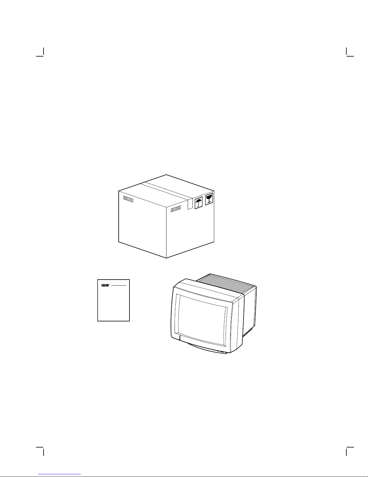
The contents in the monitor box consist of the VR320 color monitor and
this manual.
WARNING
The monitor weighs approximately 29 kg (63 lbs). Because of the
monitor weight, it will require two people to unpack the monitor
box and place it on a level surface.
VR320
Installing and Using the
VR320 Monochrome Monitor
MA-1258-89.DG
Page 9
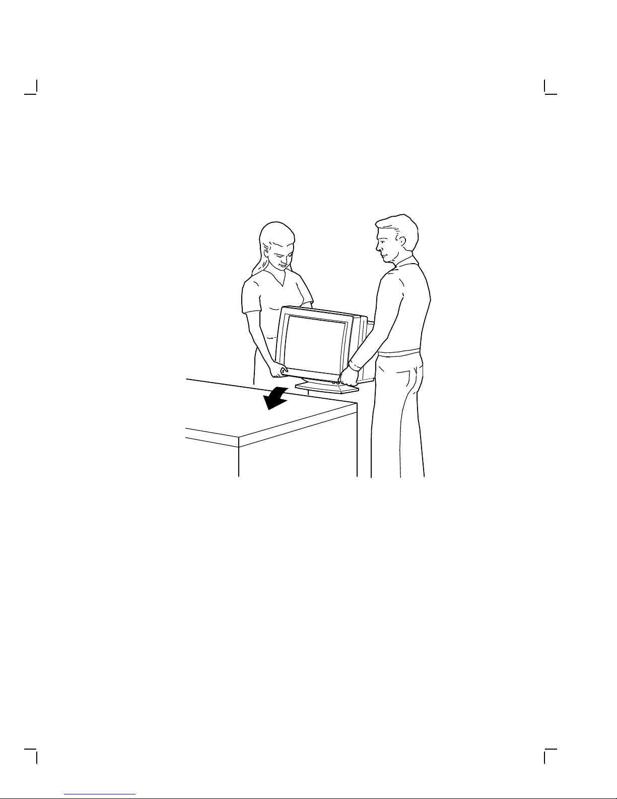
Place the monitor on a level surface.
Unpacking 1–3
MA-1259-89.DG
Page 10

2
Installation
NOTES
The monitor can operate at either 66 Hz or 72 Hz. The monitor is
preset for the system as ordered before it is shipped. If you wish
to change the monitor to another system, you need to check the
refresh rate of the new system. If it is different from the initial
system refresh rate, contact your local Customer Services office.
If your host system needs a color video option with your monitor,
make sure the option is installed.
Model
Number Pixels x Lines
VR320-CA 1280 x 1024 66 Hz Northern
VR320-C4 1280 x 1024 66 Hz Southern
VR320-DA 1280 x 1024 72 Hz Northern
VR320-D4 1280 x 1024 72 Hz Southern
Refresh
Rate Applicable Area
Hemisphere
Hemisphere
Hemisphere
Hemisphere
2–1
Page 11
2–2 Installation
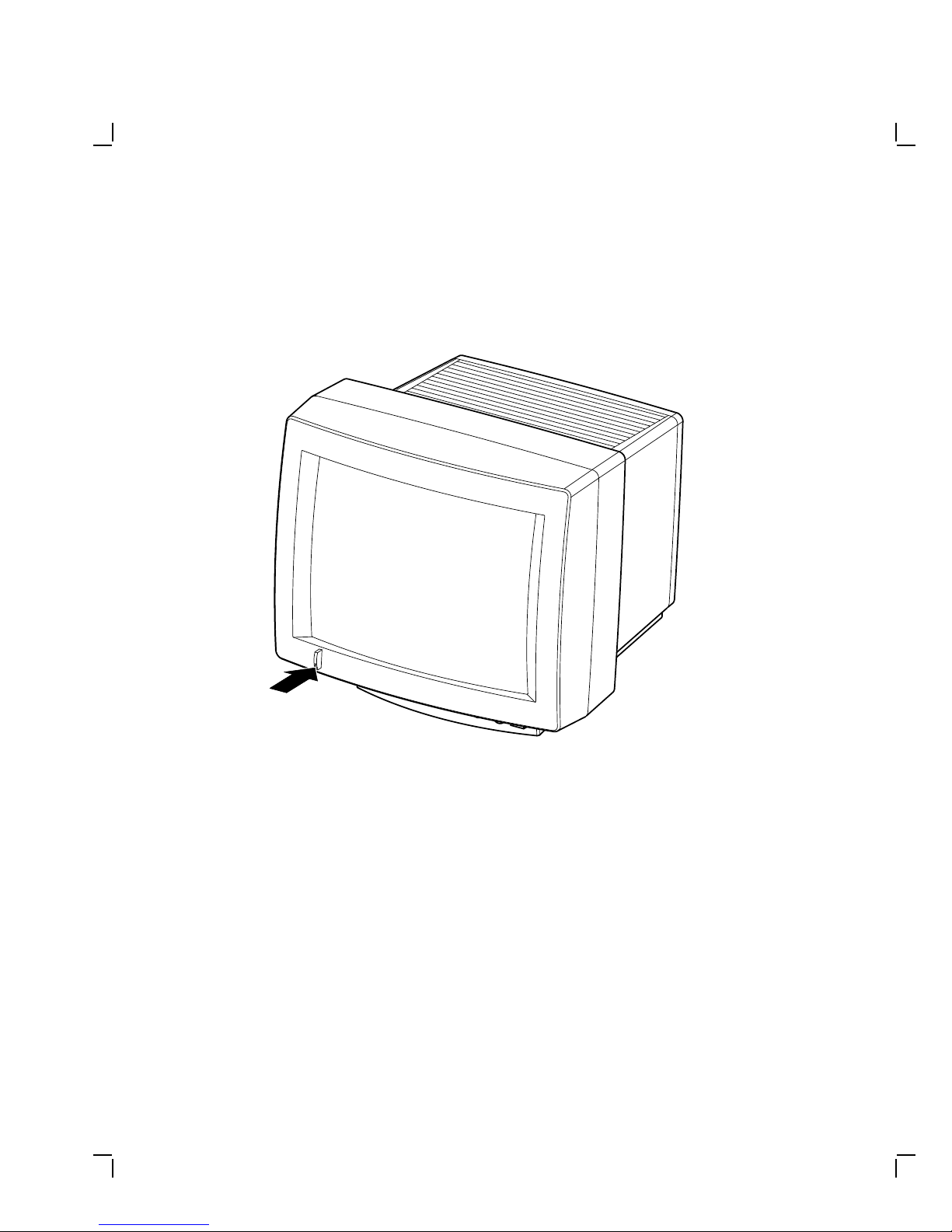
Make sure the power switch is in the out position
(off).
MA-1012-89.DG
Page 12
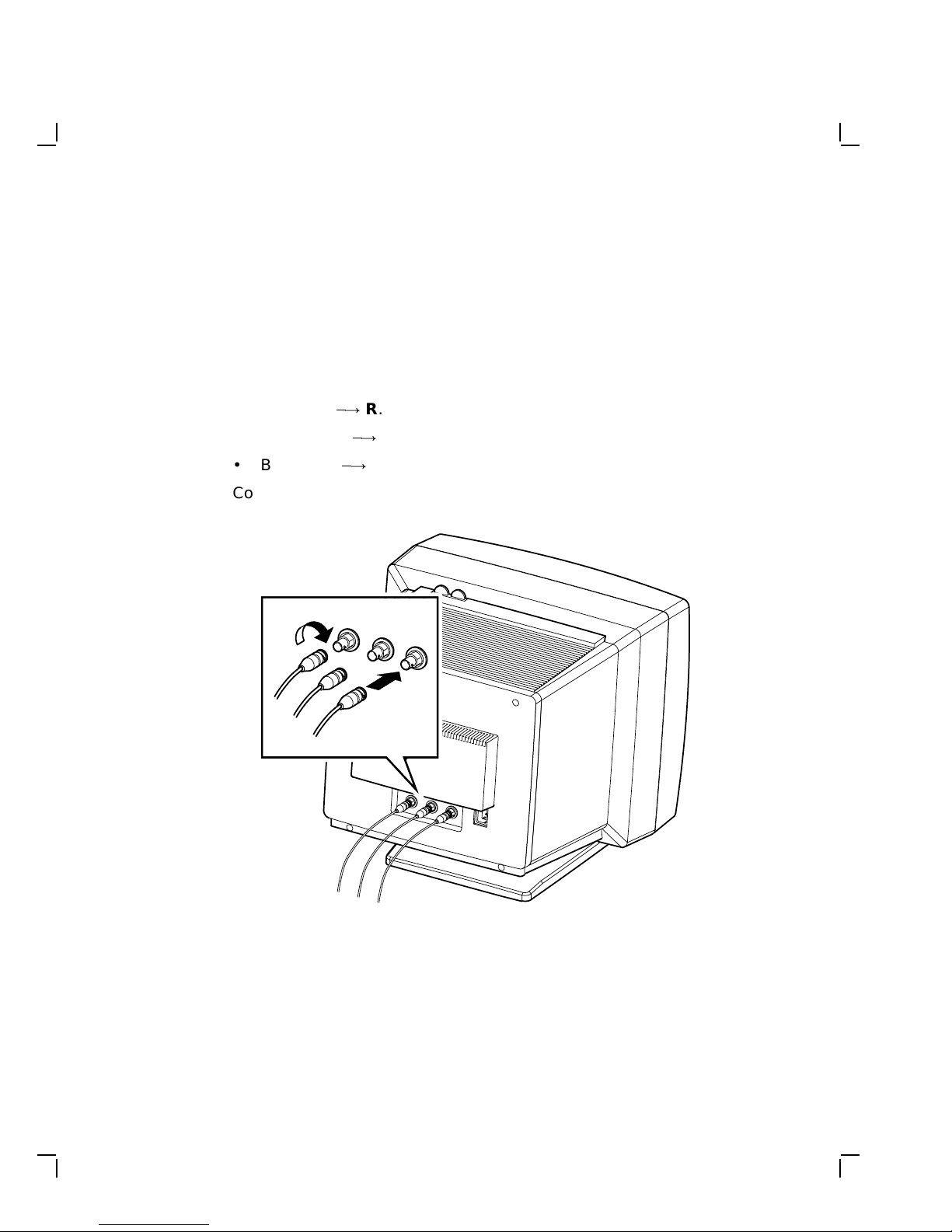
Installation 2–3
Connect the video cable to the monitor.
NOTE
The video cable is shipped with your host system.
1. Attach each BNC connector to the back of the monitor as follows.
Then turn the connector right until it locks in place.
• Red cable
• Green cable
• Blue cable
0!
0!
0!
R.
G.
B.
2. Connect the other ends of the cable to the host system.
MA-1013-89.DG
Page 13
2–4 Installation
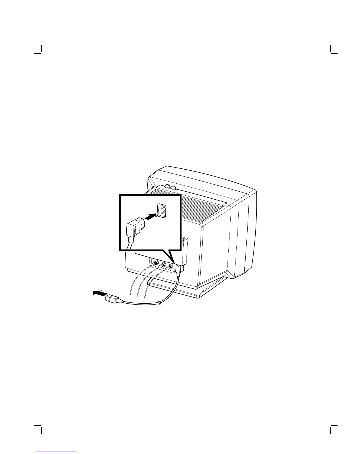
Connect the power cord.
NOTE
The power supply automatically selects the correct voltage.
1. Plug the power cord firmly into the power connector on the back of
the monitor.
2. Connect the other end of the power cord to the host system.
To Host System
MA-1014-89.DG
Page 14
3
Operation
CAUTION
To avoid damage to the monitor, allow a cold monitor to warm to
room temperature before turning it on.
Identify monitor controls and power indicator.
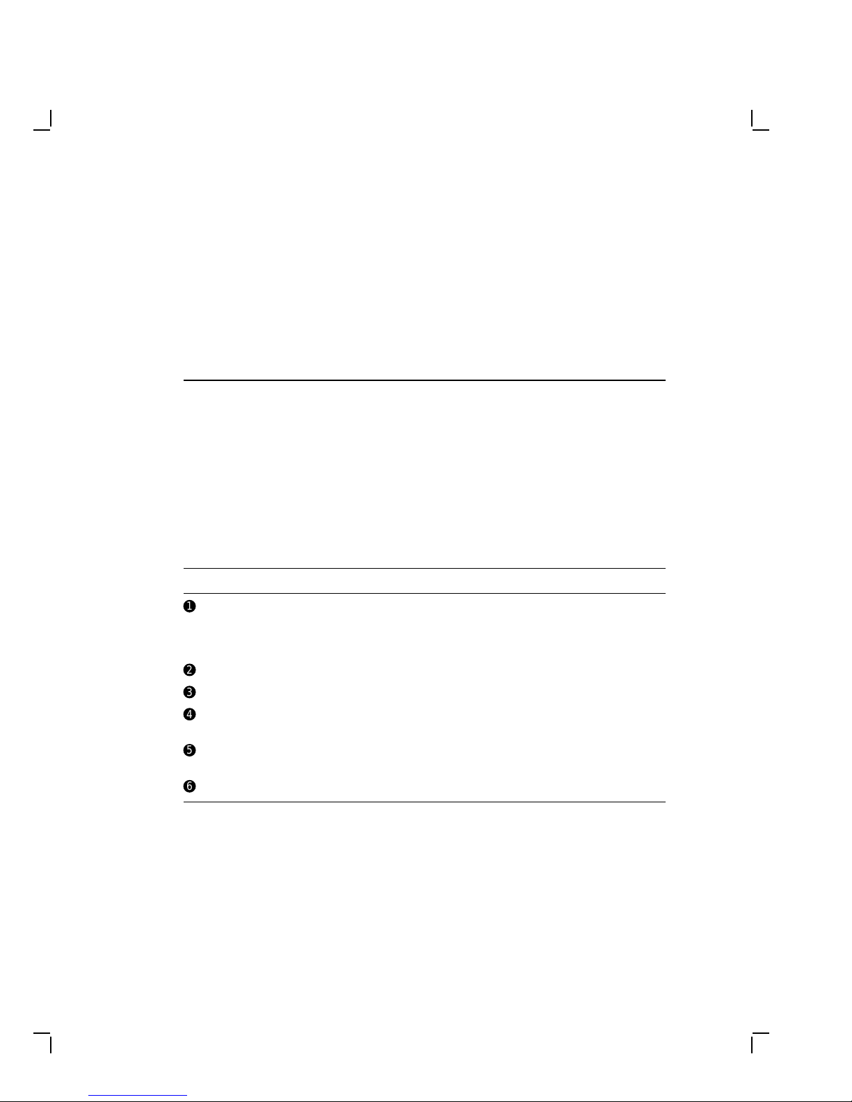
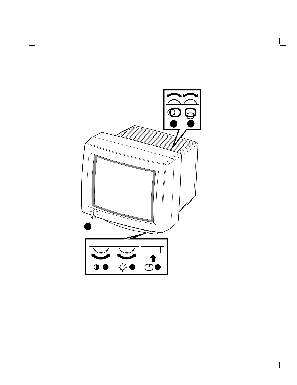
Use Table 3–1 and the next illustration to identify the monitor controls
and power indicator.
Table 3–1 Monitor Controls and Power Indicator
Item Control/Indicator Function
!
"
#
$
%
&
Power switch/
indicator
Contrast Adjusts the video display intensity.
Brightness Adjusts the video background intensity.
Horizontal centering Adjusts the horizontal position of the active
Vertical centering Adjusts the vertical position of the active
Degauss Eliminates color distortion.
Turns the power on and off. When the power
is on, the switch is lit up. For extended
monitor life, switch the power off when not
in use.
area with respect to the bezel.
area with respect to the bezel.
3–1
Page 15
3–2 Operation
4
1
5
2
3
6
Monitor Controls and Indicator
MA-1016-89.DG
Page 16
Operation 3–3
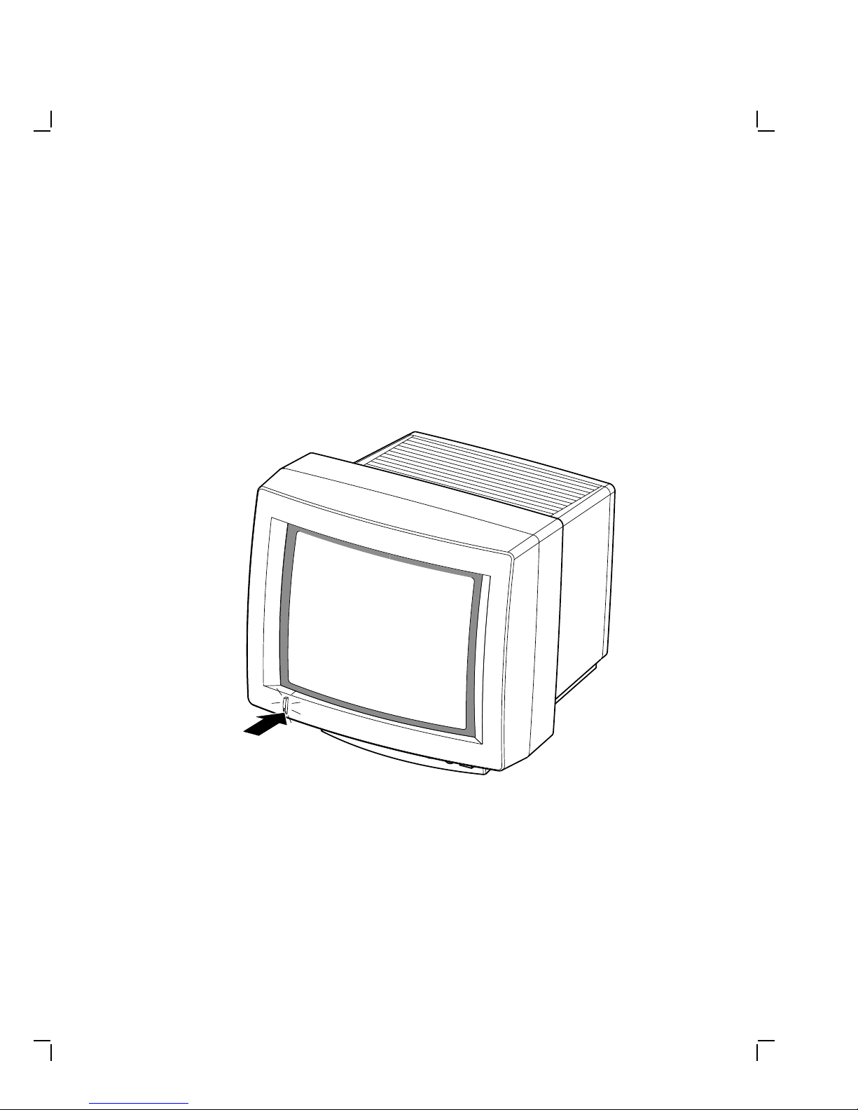
Turn the system power on.
Make sure your host system is on; then, push in the video monitor power
switch.
The power switch should light up. Wait about 20 seconds for a video
display.
NOTE
If the video display is not visible within 20 seconds, or if the
switch did not light up, refer to Chapter 4 of this manual.
MA-1015-89.DG
Page 17
3–4 Operation
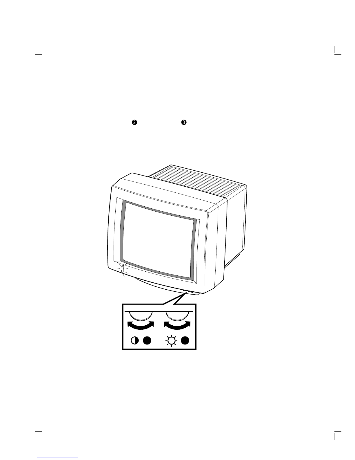
Adjust the contrast and brightness controls.
1. Set the contrast"and brightness#to the maximum level.
2. Decrease the brightness just until the background intensity
disappears.
3. Adjust the contrast to your viewing preference.
2
3
MA-1017-89.DG
Page 18
Operation 3–5
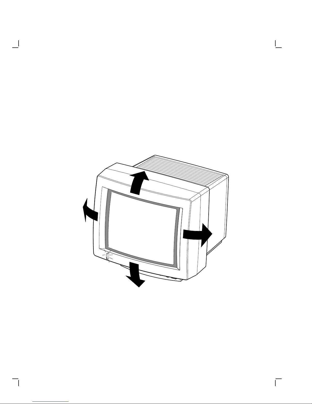
Adjust the tilt-swivel stand.
CAUTION
The monitor does not swivel in a complete circle. If you try to
swivel the monitor in a complete circle, you could damage the
base.
You can swivel the monitor about its base and still maintain the tilt angle.
Using two hands, gently press down on the top, or pull up on the bottom,
of the front of the monitor.
MA-1018-89.DG
Page 19
3–6 Operation
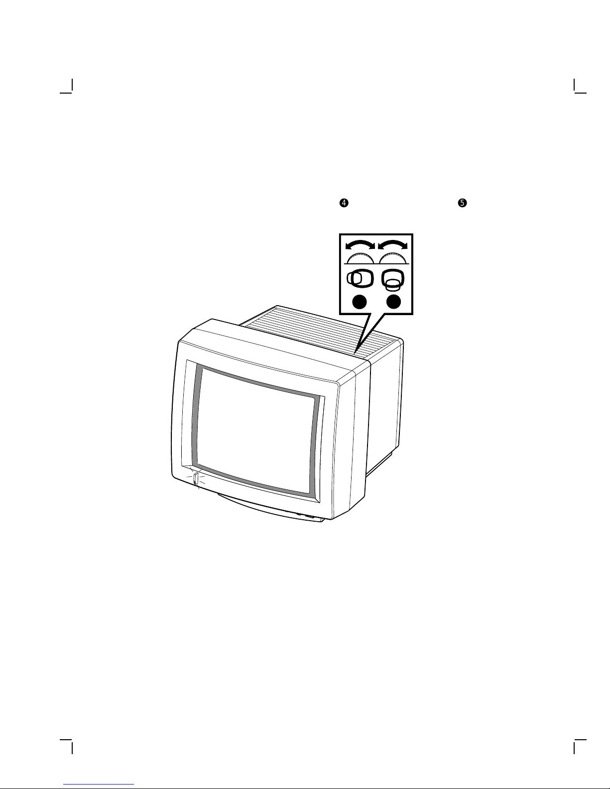
Adjust the centering controls.
If necessary, adjust the horizontal centering$and vertical centering
controls for a centered display.
4
5
%
MA-1262-89.DG
Page 20
Operation 3–7
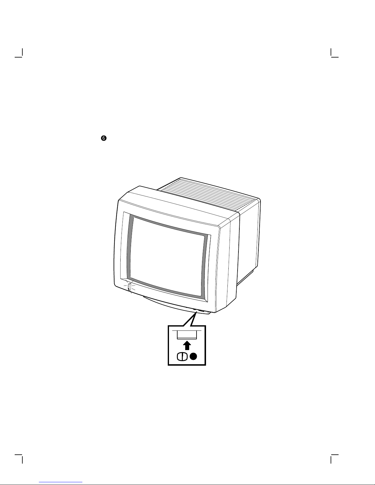
Press the degauss switch for clear color.
The monitor may develop poor color after the swivel action.
If you see other colors scattered on the screen, press the degauss
switch&.
NOTE
If the color is still poor, wait 10 minutes before pressing the
degauss switch again to allow the circuit to fully reactivate.
6
MA-1019-89.DG
Page 21

4
Maintenance
Clean the screen.
Before cleaning the screen, turn the monitor power switch off and wait 20
seconds to let static electricity dissipate.
Clean the screen with a good quality, nonabrasive, nonflammable glass
cleaner.
Identify and correct problems.
Table 4–1 will help you determine if the problem is in the monitor or in
a source external to the monitor. The following devices can be sources of
problems:
• Host video cable
• Host system
• Nearby power or electrical sources
If you have a problem with the monitor, follow these steps:
1. Note the symptoms of the problem.
2. Check your symptoms against the Symptom column in Table 4–1.
3. Check the cause(s) for that symptom in the Possible Cause column. If
the column contains more than one possible cause, check the possible
causes and their suggested solutions in the order listed.
4. Follow the steps in the Suggested Solution column.
4–1
Page 22

4–2 Maintenance
Table 4–1 Identifying and Correcting Problems
Symptom Possible Cause Suggested Solution
Power indicator
does not light
up when you
turn the monitor
power switch on.
Screen is blank,
but power
indicator is
on.
Power cord is
not connected to
the power source
or the monitor.
There is no
power at the
wall outlet.
Monitor is faulty. Turn the monitor power switch off.
Host system
screen saver
feature is
activated.
Brightness and
contrast controls
are set too low.
Host system
power switch is
not turned on.
Signal cables are
not connected to
the monitor or
the host system.
Monitor or host
system is faulty.
Turn the monitor power switch off.
Reconnect the power cord to the power
source and the monitor. Turn the
monitor power switch on.
Check the outlet by plugging in a lamp.
If the lamp does not work, call the
responsible facilities person.
Contact Customer Services.
Press any key to reactivate the display.
Increase the brightness and contrast
control settings. A raster should be
displayed.
Turn the host system power switch on.
Refer to Chapter 2 of this manual
and the host system documentation to
reconnect the signal cables.
Turn the monitor power switch off.
Contact Customer Services.
Screen displays
poor color.
Monitor has
been swiveled.
Press degauss switch to correct color
distortions.
Page 23

Table 4–1 (Cont.) Identifying and Correcting Problems
Symptom Possible Cause Suggested Solution
Maintenance 4–3
Raster can
be seen using
the brightness
control, but
no video or
cursor can be
seen using the
contrast control.
Erratic or
moving
colors on the
screen. Screen
display may
be distorted,
flickering, or
rolling. Green
color may be
missing.
Signal cables are
disconnected to
the monitor or
the host system.
Monitor or host
system is faulty.
Electromagnetic
interference is
coming from
other appliances.
(CAUTION: Before moving the monitor, turn the monitor off
and wait 20 seconds to let static electricity dissipate.)
Green signal
cable has a loose
connection or is
not connected to
the monitor or
the host system.
Wrong variation
(66 or 72 Hz) of
the monitor for
the system.
Monitor or host
system is faulty.
Refer to Chapter 2 of this manual
and the host system documentation to
reconnect the signal cables.
Turn the monitor power switch off.
Contact Customer Services.
Press Degauss switch. If color
problems cannot be corrected, then
electromagnetic interference exists.
Therefore, move any electromechanical
device, such as a fan, a motor, or an
electric pencil sharpener, away from
the monitor or move the monitor.
Refer to Chapter 2 of this manual
and the host system documentation to
reconnect the cable.
Contact Customer Services to check
your monitor and change the variation
if needed.
Turn the monitor power switch off.
Contact Customer Services.
Page 24

4–4 Maintenance
Table 4–1 (Cont.) Identifying and Correcting Problems
Symptom Possible Cause Suggested Solution
Red or blue color
is missing.
Display area is
not centered on
the screen.
Red or blue
signal cable is
loose or is not
connected to the
monitor or host
system.
Host system or
cable for the
missing color is
faulty.
Monitor is faulty. Verify this problem by again swapping
Centering
adjustments
are not correct,
or there is
magnetic
interference
in the area.
The monitor is
faulty.
Refer to Chapter 2 of this manual
and the host system documentation to
reconnect the cables.
Verify this problem by swapping the red
and blue signal cables on the monitor.
If the missing color returns, then the
host system or the cable for the missing
color is faulty.
the red and blue signal cables on the
monitor. If the missing color does not
return, then the monitor is faulty.
Turn the monitor power switch off.
Contact Customer Services.
Use the horizontal and vertical
adjustments to adjust the display
area.
Turn the monitor power switch off.
Contact Customer Services.
NOTE
If you perform all the suggested solutions and the problem still
exists, refer to the "Service" section in your host system owner’s
manual. If that does not work, refer to Chapter 5 of this manual
for service options.
Page 25

5
Service
Digital provides a wide range of maintenance programs that cover small
systems and terminals. You can use these programs to select a plan that
suits your service needs.
On-Site Repair
Digital offers fast, low-cost, quality maintenance performed at your site
by Digital-trained Service Specialists. There are several on-site services
available which are described next.
DECservice
DECservice provides on-site service with a guaranteed response time
when equipment is located within a specified distance of the service
facility. DECservice guarantees a continuous repair effort until service is
restored. You can choose the hours of coverage, up to 24 hours a day, 7
days a week.
BASIC Service
BASIC service provides on-site service during regular business hours,
Monday through Friday.
Site Servicenter
The Site Servicenter repair service provides an on-site technician for a
predetermined, periodic time interval, if you have at least 50 terminals or
small systems and can provide workspace at your site. This repair service
is provided for a variety of models.
Per Call
The Per Call service is a noncontractual offering that provides on-site
repair based on time and materials. Per Call service is available during
regular business hours, Monday through Friday.
5–1
Page 26

5–2 Service
DECall
DECall provides similar service as the Per Call service; however, the
difference is you pay a fixed fee per call with an annual retainer fee.
Off-Site Service
Digital also provides several options for off-site service which are
described below.
Carry-In Servicenters
Digital Carry-In Servicenters are located in major cities around the
world. They offer convenient, cost-effective repair service with a 48-hour
turnaround time. Both contract and Per Call coverage is offered.
DECmailer
DECmailer provides mail-in service for module and subassembly repairs.
DECmailer provides a five-day turnaround time.
How To Get Service
Digital has a central service center in your area to help you keep your
system running efficiently. To find out more about Digital hardware and
software service offerings:
In the United States
Call 1-800-554-3333
Worldwide
Contact your local Digital Customer Services office.
Page 27

6
Specifications
Dimensions
Height 457 mm (18 in)
Width 495 mm (19.5 in)
Depth 452 mm (17.8 in)
Weight
Tilt Range -5° forward to +15° backward
Swivel Range ± 90° (left and right)
Display
Cathode ray tube (CRT) 483 mm (19 in) diagonal
Display Area 1280 pixels horizontal x 1024 lines vertical.
Light Transmissivity 58% nominal
29 kg (63 lb)
Approximate picture size = 342 mm (13.5
in) x 273 mm (10.75 in) with a 5:4 aspect
ratio.
6–1
Page 28

6–2 Specifications
Video Input Red (with sync) 1 Vpp, 75 ohm, ac or dc
Video Timing See Table 6–1.
Electrical Requirements
AC input voltage 88 - 132 Vac or 176 - 264 Vac,
Line frequency 47 to 63 Hz
Power consumption 220 watts maximum
Operating Temperature 10° to 40° C (50° to 104° F)
Humidity 10% to 95% relative humidity
coupled
Green (with sync) 1 Vpp, 75 ohm, ac or dc
coupled
Blue (with sync) 1 Vpp, 75 ohm, ac or dc
coupled
auto-ranging, single phase, 3-wire
Maximum wet bulb = 32° C
Minimum dew point = 2° C (noncondensing)
Page 29
Specifications 6–3
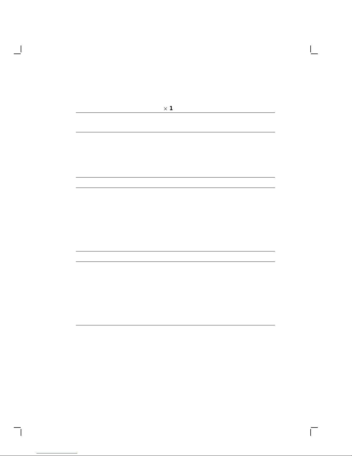
Table 6–1 Video Timing—128021024 Resolution
Pixels: 1280 x 1024 1280 x 1024
Refresh Rate: @72 Hz @66 Hz
Horizontal frequency 77.13 kHz 70.66 kHz
Vertical frequency 72.56 Hz 66.47 Hz
Pixel frequency 130.81 MHz 119.84 MHz
Pixel period 7.64 ns 8.34 ns
Horizontal Timing no. pixels µs µs
Entire line 1696 12.97 14.15
Active visible line 1280 9.79 10.68
Blanking interval 416 3.18 3.47
Sync front porch 32 0.245 0.267
Sync pulse 160 1.22 1.34
Sync back porch 224 1.71 1.87
Vertical Timing no. lines ms ms
Vertical period
(Entire frame)
Visible raster 1024 13.28 14.49
Blanking interval 39 0.506 0.552
Sync front porch 3 0.03889 0.04246
Sync pulse 3 0.03889 0.04246
Sync back porch 33 0.4279 0.4670
1063 13.78 15.04
 Loading...