

Digital Equipment VAXstation 4000 Model 60, VAXstation 4000 Model 90 Upgrade Manual
VAXstation 4000 Model 60
to VAXstation 4000 Model 90
Upgrade Guide
EK-VX690-UP. A01
Digital Equipment Corporation

August 1992
The information in this document is subject to change without notice and should not
be construed as a commitment by Digital Equipment Corporation. Digital Equipment
Corporation assumes no responsibility for any errors that may appear in this document.
Possession, use, duplication, or dissemination of the software described in this
documentation is authorized only pursuant to a valid written license from Digital or
the third-party owner of the software copyright.
No responsibility is assumed for the use or reliability of software on equipment that is
not supplied by Digital Equipment Corporation.
Copyright © Digital Equipment Corporation 1992
All Rights Reserved.
Printed in U.S.A.
The following are trademarks of Digital Equipment Corporation: DEC, DEC PHIGS,
DIGITAL, ThinWire, TK, TURBOchannel, VAX DOCUMENT, VAXstation, and the
DIGITAL logo.
MS–DOS is a registered trademark of Microsoft Corporation.
This document was prepared and published by Documentation and Course Development,
Digital Equipment Corporation

Contents
About This Guide
1 Overview of the VAXstation 4000 Model 60 and the VAXstation 4000 Model 90
Overview . . . . . . . . . . . . . . . . . . . . . . . . . . . . . . . . . . . . . . . . . . . . . . . . . . . . . . . 1–1
VAXstation 4000 Model 60 Product Description . . . . . . . . . . . . . . . . . . . . . . . . 1–2
Contents of the Upgrade Kit . . . . . . . . . . . . . . . . . . . . . . . . . . . . . . . . . . . . . . . . 1–3
VAXstation 4000 Model 90 Product Description . . . . . . . . . . . . . . . . . . . . . . . . 1–7
2 Disassembly of the VAXstation 4000 Model 60 and Removal of Components
Overview . . . . . . . . . . . . . . . . . . . . . . . . . . . . . . . . . . . . . . . . . . . . . . . . . . . . . . . 2–1
Preparing VAXstation Model 60 for Disassembly . . . . . . . . . . . . . . . . . . . . . . . 2–3
Shutting Down Peripherals and Disconnecting Cables . . . . . . . . . . . . . . . . . . . 2–5
Protecting Against Static . . . . . . . . . . . . . . . . . . . . . . . . . . . . . . . . . . . . . . . . . . . 2–6
System FRU Locations . . . . . . . . . . . . . . . . . . . . . . . . . . . . . . . . . . . . . . . . . . . . 2–8
Removing Top Cover of the VAXstation 4000 Model 60 . . . . . . . . . . . . . . . . . . 2–9
Removing Mass Storage Devices . . . . . . . . . . . . . . . . . . . . . . . . . . . . . . . . . . . 2–10
Removing Power Supply . . . . . . . . . . . . . . . . . . . . . . . . . . . . . . . . . . . . . . . . . . . 2–12
Removing Lights and Switches Module . . . . . . . . . . . . . . . . . . . . . . . . . . . . . . . 2–13
Removing Graphics Module (if applicable) . . . . . . . . . . . . . . . . . . . . . . . . . . . . 2–15
Removing Synchronous Communications Option (if applicable) . . . . . . . . . . . 2–19
Removing TURBOchannel Adapter Module and Option (if applicable) . . . . . . 2–20
Removing KA46 System Module (CPU) . . . . . . . . . . . . . . . . . . . . . . . . . . . . . . 2–21
Removing MS44 Memory SIMMs . . . . . . . . . . . . . . . . . . . . . . . . . . . . . . . . . . . . 2–22
Removing Ethernet ROM . . . . . . . . . . . . . . . . . . . . . . . . . . . . . . . . . . . . . . . . . . 2–24
Swapping Medallions . . . . . . . . . . . . . . . . . . . . . . . . . . . . . . . . . . . . . . . . . . . . . 2–25
3 Installation of Upgrade Components and Reassembly of the New VAXstation 4000
Model 90
Overview . . . . . . . . . . . . . . . . . . . . . . . . . . . . . . . . . . . . . . . . . . . . . . . . . . . . . . . 3–1
System FRU Locations . . . . . . . . . . . . . . . . . . . . . . . . . . . . . . . . . . . . . . . . . . . . 3–3
Installing Ethernet ROM . . . . . . . . . . . . . . . . . . . . . . . . . . . . . . . . . . . . . . . . . . . 3–5
Installing MS44 Memory SIMMs . . . . . . . . . . . . . . . . . . . . . . . . . . . . . . . . . . . . . 3–6
Installing the KA49 System Module (CPU) . . . . . . . . . . . . . . . . . . . . . . . . . . . . 3–10
Installing TURBOchannel Adapter Module and Option (if applicable) . . . . . . . 3–11
Installing Synchronous Communications Option (if applicable) . . . . . . . . . . . . 3–12
Swapping SPXg/gt Diagnostic ROM (if applicable) . . . . . . . . . . . . . . . . . . . . . . 3–13
Installing Graphics Module (if applicable) . . . . . . . . . . . . . . . . . . . . . . . . . . . . . 3–14
Contents–iii

Installing Lights and Switches Module . . . . . . . . . . . . . . . . . . . . . . . . . . . . . . . . 3–18
Installing Power Supply . . . . . . . . . . . . . . . . . . . . . . . . . . . . . . . . . . . . . . . . . . . . 3–19
Installing Mass Storage Devices . . . . . . . . . . . . . . . . . . . . . . . . . . . . . . . . . . . . . 3–20
Restoring the System . . . . . . . . . . . . . . . . . . . . . . . . . . . . . . . . . . . . . . . . . . . . . 3–21
Appendix A Packing Instructions and Upgrade Return Forms
Packing Instructions . . . . . . . . . . . . . . . . . . . . . . . . . . . . . . . . . . . . . . . . . . . . . . A–1
Digital Services Upgrade Worksheet ..... . . . . . . . . . . . . . . . . . . . . . . . . . . . . A–3
Installation Receipt—Customer Copy . . . . . . . . . . . . . . . . . . . . . . . . . . . . . . . . . A–5
Installation Receipt—Digital Services Copy . . . . . . . . . . . . . . . . . . . . . . . . . . . . A–7
Return Material Checklist . . . . . . . . . . . . . . . . . . . . . . . . . . . . . . . . . . . . . . . . . . A–9
Customer Administrative Services District Offices . . . . . . . . . . . . . . . . . . . . . . . A–11
Index
Examples
2–1 Typical Screen Display of a SHOW CONFIG Command (Model 60) . . . . . . . . 2–4
3–1 Typical Screen Display of a SHOW CONFIG Command (Model 90) . . . . . . . . 3–23
Figures
2–1 VAXstation 4000 Model 60 FRU Locations . . . . . . . . . . . . . . . . . . . . . . . . . . . . . 2–8
2–2 Avoid Touching This Area . . . . . . . . . . . . . . . . . . . . . . . . . . . . . . . . . . . . . . . . . . 2–13
2–3 Removing a MS44 Memory SIMM (Model 60) . . . . . . . . . . . . . . . . . . . . . . . . . . 2–23
3–1 VAXstation 4000 Model 90 FRU locations . . . . . . . . . . . . . . . . . . . . . . . . . . . . . 3–4
3–2 Memory Slots in the Model 90 . . . . . . . . . . . . . . . . . . . . . . . . . . . . . . . . . . . . . . . 3–7
3–3 Installing the First MS44 Memory SIMM (Model 90) . . . . . . . . . . . . . . . . . . . . . 3–9
3–4 Installing the Synchronous Communications Option. . . . . . . . . . . . . . . . . . . . . . 3–12
Tables
1–1 Contents of PV71U-AF . . . . . . . . . . . . . . . . . . . . . . . . . . . . . . . . . . . . . . . . . . . . . 1–4
1–2 Contents of PV71U-AH . . . . . . . . . . . . . . . . . . . . . . . . . . . . . . . . . . . . . . . . . . . . 1–5
1–3 Contents of PV71U-AJ . . . . . . . . . . . . . . . . . . . . . . . . . . . . . . . . . . . . . . . . . . . . . 1–6
3–1 Memory Configurations (Model 90) . . . . . . . . . . . . . . . . . . . . . . . . . . . . . . . . . . . 3–8
Contents–iv

AboutThisGuide
Purpose of this
Guide
Who Should
Use This Guide
Note
This guide describes how to upgrade a VAXstation 4000 Model
60 to a VAXstation 4000 Model 90, a faster, more powerful
VAXstation. The VAXstation 4000 Model 90 utilizes the new
KA49 CPU module, which houses up to 128 Mbytes of SIMM
main memory.
The upgrade is accomplished by removing the Ethernet ROM
and the SIMM memory modules from the VAXstation 4000 Model
60 KA46 CPU module and installing them into the KA49 CPU
module. Also one of the following graphics modules (LCSPX,
SPXg or SPXgt) can be installed. The SPXg and SPXgt modules
require a SPXg/gt diagnostic ROM with a version of 1.2 or higher.
Only Digital Services or qualified self-maintenance personnel
should perform this upgrade. You must have a working knowledge
of, and experience working on, the internal hardware devices of
the VAXstation 4000 systems. If you are not qualified to perform
this upgrade, call Digital Services to schedule an upgrade.
It is the customer’s responsibility to perform all software
backups of the system and user disks. All backups should
be performed before the Digital Services representative
arrives at the site. Backups are mandatory to ensure that
data is not lost during the upgrade.
Continued on next page
v
About This Guide, Continued
Structure of
this Guide
Related
Documentation
This guide is comprised of three chapters and one appendix:
Chapter 1 describes an overview of the VAXstation 4000
Model 60 and Model 90. It also lists the contents of the
upgrade kits.
Chapter 2 describes how to disassemble the VAXstation
4000 Model 60 and remove the necessary components for the
upgrade.
Chapter 3 describes how to install the necessary components
and reassemble the VAXstation 4000 Model 90.
Appendix A describes how to pack the modules and
components to be sent back to Digital and also provides
the necessary forms to be completed and returned to Digital
after the upgrade.
If additional information is needed for the procedures in this
guide, refer to the following documents:
The following documents provide additional information relating
to the VAXstation 4000 Model 60:
VAXstation 4000 Options Installation Guide, EK-VAXOP-IN
VAXstation 4000 Model 60 Service Information,
EK-V466B-SV
The following documents provide additional information relating
to the VAXstation 4000 Model 90:
VAXstation 4000 Options Installation Guide, EK-VAXOP-IN
VAXstation 4000 Model 90 Service Information,
EK-KA490-SV
VAXstation 4000 Model 90 Owner’s Installation Guide,
EK-VAXOG-IN
Continued on next page
vi
About This Guide, Continued
Conventions
Used in this
Guide
The following conventions are used in this guide:
Convention Meaning
Return
Warning Warnings contain information to prevent
Caution Cautions provide information to prevent damage
Note Notes provide general information about the
A name enclosed in a box in interactive
examples indicates a key you press on the
keyboard.
personal injury. Read warnings carefully.
to equipment or software. Read cautions
carefully.
current topic.
vii


Chapter 1
OverviewoftheVAXstation4000Model
60andtheVAXstation4000Model90
Overview
Purpose
The purpose of this chapter is to provide an overview of the
VAXstation 4000 Model 60, and the VAXstation 4000 Model 90,
and to provide a list of the contents of the upgrade kits.
1–1
VAXstation4000 Model 60 Product Description
Product
Description
The VAXstation 4000 Model 60 system is a single-user engineering
workstation, based on the KA46 system module. The Model 60
includes:
An LK401 keyboard
A VSXXX-GA mouse or VSXXX-AB tablet
A monochrome or color video monitor
One or more storage devices
SCSI and Ethernet controllers
Memory SIMMs, which supports up to 108 MB
Each Model 60 system is housed in a desktop BA46 system
enclosure that contains a KA46 system module and an H7819-AA
power supply.
1–2

Contents of the Upgrade Kit
Note
Upgrade Kit
Versions
If a system started out as a VAXstation 3100 and was
upgraded to a VAXstation 4000 Model 60, then it may not
be upgraded to a VAXstation 4000 Model 90.
The following is a list of the various PV71U upgrade kits that can
be used to upgrade to a VAXstation 4000 Model 90:
Part
Number Description
PV71U-AF Includes the LCSPX graphics module
PV71U-AH For the SPXg graphics module
PV71U-AJ For the SPXgt graphics module
Continued on next page
1–3
Contents of the Upgrade Kit, Continued
PV71U-AF
Table 1–1 lists the contents of the PV71U-AF upgrade kit.
Table 1–1 Contents of PV71U-AF
Part Number Description
75-00003-04 Software licenses
70-30299-01 VAXstation Model 60 to 90, which includes the
following:
Part Number Contents
54-21177-01 CPU system module
54-21795-01 LCSPX graphics module
EK-VAXOG-DK Documentation kit, which
includes the following:
– VS4000 Owner’s
Installation Guide
– VS4000 Options
Installation Guide
– VS4000 Quick Installation
EK-VX690-UP VAXstation 4000 Model 60
to VAXstation 4000 Model 90
Upgrade Guide
74-41856-08 A Medallion, VAXstation 4000 90
74-42680-02 Clamp, video board
12-36175-01 Disposable wrist strap
Card
Continued on next page
1–4

Contents of the Upgrade Kit, Continued
PV71U-AH
Table 1–2 lists the contents of the PV71U-AH upgrade kit.
Table 1–2 Contents of PV71U-AH
Part Number Description
75-00020-01 PHIGS 3D software licenses, including the DEC
PHIGS/V RT license.
75-00003-04 Software licenses
70-30299-02 VAXstation Model 60 to 90, which includes the
following:
Part Number Contents
54-21177-01 CPU system module
EK-VAXOG-DK Documentation kit, which
includes the following:
– VS4000 Owner’s
Installation Guide
– VS4000 Options
Installation Guide
– VS4000 Quick Installation
EK-VX690-UP VAXstation 4000 Model 60
to VAXstation 4000 Model 90
Upgrade Guide
74-41856-09 A Medallion, VAXstation 4000 90
SPXg
23-226E8-00 SPXg/gt diagnostic ROM
12-36175-01 Disposable wrist strap
Card
Continued on next page
1–5

Contents of the Upgrade Kit, Continued
PV71U-AJ
Table 1–3 lists the contents of the PV71U-AJ upgrade kit.
Table 1–3 Contents of PV71U-AJ
Part Number Description
75-00020-01 PHIGS 3D software licenses, including the DEC
PHIGS/V RT license.
75-00003-04 Software licenses
70-30299-03 VAXstation Model 60 to 90, which includes the
following:
Part Number Contents
54-21177-01 CPU system module
EK-VAXOG-DK Documentation kit, which
includes the following:
– VS4000 Owner’s
Installation Guide
– VS4000 Options
Installation Guide
1–6
– VS4000 Quick Installation
Card
EK-VX690-UP VAXstation 4000 Model 60
to VAXstation 4000 Model 90
Upgrade Guide
74-41856-10 A Medallion, VAXstation 4000 90
SPXgt
23-226E8-00 SPXg/gt diagnostic ROM
12-36175-01 Disposable wrist strap
VAXstation4000 Model 90 Product Description
Product
Description
The VAXstation 4000 Model 90 is housed in a BA46 system
enclosure. The KA49 system module with either 4-MB or 16-MB
SIMM modules form the CPU/memory subsystem.
The VAXstation 4000 Model 90 supports three graphics options:
Option Description
LCSPX Standard 2D graphics
SPXg 8-Plane 3D graphics
SPXgt 24-Plane 3D graphics
Some of the main features of the VAXstation 4000 Model 90 are:
Up to 128 Mbytes of SIMM main memory
ThinWire or Thickwire connection for Ethernet network
Subsystem uses the SCSI-1 bus to communicate with mass
storage devices
A 16 bit programmed I/O port connection for synchronous
communications
Four serial lines controllers for:
— Keyboard
— Pointing device
— Printer
— Asynchronous communication
Audio input/output connector supported by the sound
generator interface
Continued on next page
1–7
VAXstation4000Model 90Product Description,Continued
Product
Description
(continued)
ROM-based diagnostics (field programmable flash ROMs)
for:
— Power-up self-test
— User selected self-test
— System level tests
VMS software distribution by:
— CDROM disk
— TK tape
— VMS Version 5-5.2 or higher
— System down line loaded over Ethernet
MS–DOS applications distribution by floppy diskette
1–8

Chapter 2
DisassemblyoftheVAXstation4000
Model60andRemovalofComponents
Overview
Purpose
Caution
Note
The purpose of this chapter is to provide information so that
Digital Services Engineers or knowledgeable Digital customers
can disassemble an existing VAXstation 4000 Model 60 and
remove the necessary components for the upgrade.
Only Digital Services or qualified self-maintenance
personnel should perform this upgrade. You must have
a working knowledge of, and experience working on,
the internal hardware devices of the VAXstation 4000
systems. If you are not qualified to perform this upgrade,
call Digital Services to schedule an upgrade.
It is the customer’s responsibility to back up the software
before Digital Services personnel arrive at the site. This
is important to ensure that data is not lost during the
service process. The customer should also shut down the
workstation software. Before performing any maintenance
work, Digital Services personnel must confirm that the
customer has completed both of these tasks.
Continued on next page
2–1

Overview, Continued
Summary
of Removal
Process
The following table summarizes the recommended removal
process and lists the applicable page number for reference to
that procedure.
Found
on
Procedure
Preparing VAXstation 4000 Model 60 for disassembly 2-3
Shutting down peripherals and disconnecting cables 2-5
Protecting against static 2-6
Removing top cover of the VAXstation 4000 Model 60 2-9
Removing mass storage devices 2-10
Removing power supply 2-12
Removing lights and switches module 2-13
Removing graphics module 2-15
Removing synchronous communications option 2-19
Removing TURBOchannel adapter module and option 2-20
Removing KA46 system module (CPU) 2-21
Page
Removing MS44 memory SIMMs 2-22
Removing Ethernet ROM 2-24
Swapping medallions 2-25
2–2
Preparing VAXstationModel 60 for
Disassembly
Run SHOW
CONFIG
Command
To run the SHOW CONFIG command, complete the following
steps and refer to Example 2–1.
Step Action
1 Press the Halt button located behind the door in the front
of the system box.
Results:
screen.
2 Enter SHOW CONFIG at the console prompt and press
Return
>>> SHOW CONFIG
3 Record the Ethernet hardware address. This address will
be verified upon completion of the upgrade.
4 Record the SPXg/gt diagnostic ROM version. If the
version is Version 1.1 or lower, then you will need to
replace the ROM during the assembly.
The system displays the console prompt on the
.
Return
Continued on next page
2–3

Preparing VAXstationModel 60 for
Disassembly,Continued
Example 2–1 Typical Screen Display of a SHOW CONFIG Command (Model 60)
KA46-A V1.1-31E-V4.0 ! CPU type and firmware revision
08-00-2B-F3-31-03 ! Ethernet hardware address
16 MB ! Total memory
DEVNBR DEVNAM INFO
------ ------ ---1 NVR OK ! Non-volatile RAM
2 LCG OK ! 2D high res. color graphics rev 2.7
3 DZ OK ! Serial line controller
4 CACHE OK ! Cache memory
5 MEM OK ! Memory configuration
6 FPU OK ! Floating point unit
7 IT OK ! Interval Timer
8 SYS OK ! Other system functions
9 NI OK ! Ethernet
10 SCSI OK ! SCSI and drives
11 AUD OK ! Sound
12 COMM OK ! DSW21 communications device
>>>
HR - 8 PLN FB -2.7
16MB = SY=8MB, S0/S1=8MB, S2/S3=0MB, S4/S5=0MB
1-RZ23L 6-INITR ! One RZ23L at ID 1, system at ID 6.
2–4

Shutting Down Peripherals and Disconnecting Cables
Shut Down the
System
Warning
Disconnect
Cables
After shutting down the operating system, turn the system
peripherals off in the following order:
1. System unit
2. Monitor
3. Printer, modem, and any other equipment
4. Expansion boxes
The monitor power should be off for at least three minutes
before removing the power cord. You should remove the
power cord before moving the monitor.
The monitor is heavy and may require two people to lift it.
Disconnect the following cables from the back of the system in the
following order:
1. System power cord, first from the wall and then from the
system unit
2. Monitor power cord (set monitor aside)
3. Keyboard cable
4. Mouse cable
5. ThinWire Ethernet and/or standard Ethernet
connector/terminator
6. SCSI terminator or external SCSI cable
7. Monitor video cable
8. Printer and communications cables
2–5
Protecting Against Static
Use the
Antistatic Wrist
Strap
Note
The following rules must be adhered to while handling system
components:
Wear a properly grounded antistatic wrist strap.
Any module or device removed from the system unit must be
placed on an antistatic mat.
It is recommended that you have two antistatic mats for
which to place all the removed devices and components.
Continued on next page
2–6

Protecting Against Static, Continued
Static
Protection
Method
To protect against static, complete the following steps:
If you have... Then...
An alligator clip
1. Place the antistatic strap on your
wrist.
2. Attach the alligator clip to the
metal latch located on the left
center of the power supply. Refer
to Figure 2–1.
A disposable wrist strap
1. At the wrist end, wrap the shiny
black side firmly around the
wrist touching the skin.
2. At the system end, peel the strip
off the metal grounding contact
and stick the contact to the inside
rear of the enclosure.
2–7
System FRU Locations
System FRU
Locations
Note
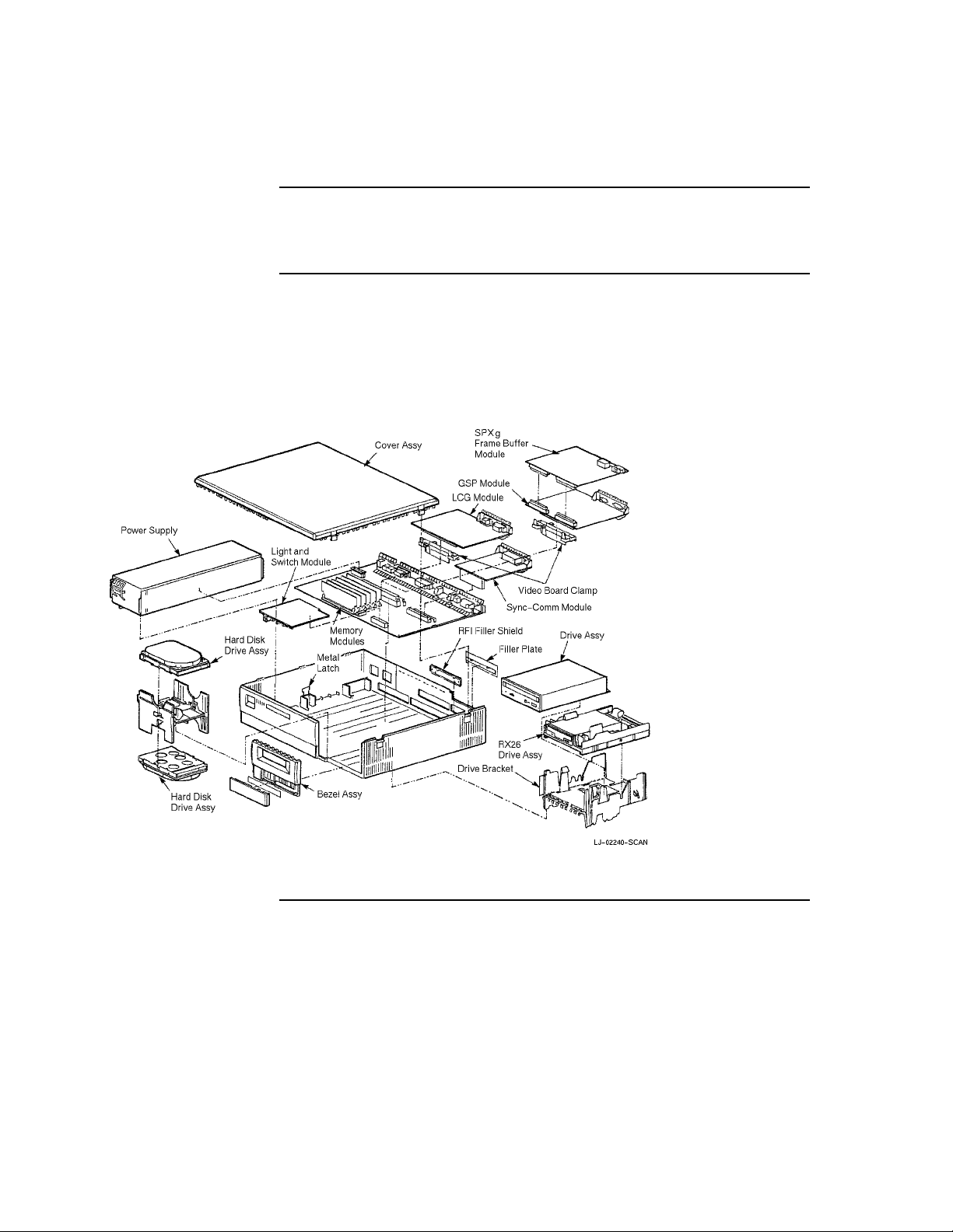
Figure 2–1 VAXstation 4000 Model 60 FRU Locations
Refer to Figure 2–1 for the VAXstation 4000 Model 60 FRU
locations mentioned in this chapter.
The SPXgt, TURBOchannel adapter module, and any
TURBOchannel option are not shown in Figure 2–1.
2–8

Removing TopCover of the VAXstation 4000 Model 60
Warning
Remove the
Top Cover
Be careful not to touch the sharp edges of the system cover.
The top cover of the VAXstation 4000 Model 60 needs to be
removed to gain access to the modules and components in the
BA46 system enclosure.
To remove the top cover, complete the following steps:
Step Action
1 Carefully release the latches on the right side of the
system unit.
2 Pull the cover up and away from the system. You will
need to pull forcefully to release the retention devices on
the middle front and rear edges of the cover.
3 Place the cover aside.
2–9
 Loading...