

Digital Equipment VAXstation 4000/90 Series Owner's And System Installation Manual

VAXstation4000Model90Series
Owner’sand System Installation
Guide
Order Number: EK–VAXOG–IN. B01
Digital Equipment Corporation
Maynard, Massachusetts

First Printing, August 1992
Second Printing, March 1994
Digital Equipment Corporation makes no representations that the use of its
products in the manner described in this publication will not infringe on
existing or future patent rights, nor do the descriptions contained in this
publication imply the granting of licenses to make, use, or sell equipment or
software in accordance with the description.
© Digital Equipment Corporation March 1994. All Rights Reserved.
The postpaid Reader’s Comments form at the end of this document requests
your critical evaluation to assist in preparing future documentation.
The following are trademarks of Digital Equipment Corporation: DEC,
DECconnect, DECwindows, ThinWire, RX, VAX, VAXstation, OpenVMS, and
the DIGITAL logo.
S2530
This document is available on CDROM.
This document was prepared using VAX DOCUMENT Version 2.1.

Contents
Preface ..................................................... xi
1 Your VAXstation 4000 Model 90 System
Introduction . . . ................................... 1–1
Chapter Topics . ................................... 1–1
System Capabilities ................................... 1–1
Overview of Features ............................... 1–1
The VAXstation 4000 Model 90 System ................. 1–2
System Components ................................... 1–3
Components Shipped ............................... 1–3
System Components ................................ 1–4
Front of System Unit ............................... 1–5
Front Components ................................. 1–6
Back of System Unit ............................... 1–7
Component Descriptions . ........................... 1–8
Available Options . . ................................... 1–9
Options ......................................... 1–9
Ordering Options .................................. 1–11
Installing Options ................................. 1–11
2 Installing Your VAXstation 4000
Introduction . . . ................................... 2–1
Chapter Topics . ................................... 2–1
Installing Your System ................................. 2–2
Installation Overview ............................... 2–2
Assemble the T-connector . ........................... 2–2
Attach the Loopback and T-connector .................. 2–3
Connect the Mouse and Keyboard . . ................... 2–4
Attach the Monitor Cables ........................... 2–5
Recommended Power Source ......................... 2–5
Universal Strain Relief Strap ......................... 2–6
iii

Attach the Monitor Video Cable ....................... 2–7
Video In/Video Out Connectors........................ 2–7
Attach the Monitor Power Cord ....................... 2–8
Factory Installed Software Sticker ..................... 2–9
Connect the System Power Cord ...................... 2–10
Turn On (|) Your System . . . ........................ 2–11
Successful Start-Up Display. . ........................ 2–12
Putting Your System in Console Mode ..................... 2–13
Console Mode ..................................... 2–13
Halt Button ...................................... 2–13
Recording Information About Your System . ................ 2–14
Why Record Information?............................ 2–14
Where to Find Information . . ........................ 2–14
Attaching the Network Label . ........................ 2–16
3 Connecting Your System to the Network
Introduction ...................................... 3–1
Chapter Topics .................................... 3–1
Verifying the Ethernet Subsystem ........................ 3–2
Steps to Verify .................................... 3–2
Connecting to the Network ............................. 3–3
Connecting to Standard Ethernet ..................... 3–3
Connecting to ThinWire Ethernet ..................... 3–5
Verifying the Ethernet Connection ........................ 3–8
Verify Command . . ................................ 3–8
Removing a System from ThinWire Ethernet................ 3–9
Caution: Follow Shutdown Procedures . ................ 3–9
Removal Steps .................................... 3–9
4 Using Your System
Introduction ...................................... 4–1
Chapter Topics .................................... 4–1
Turning Your Workstation On and Off ..................... 4–2
Turning On the Monitor ............................. 4–2
Turning On Your System . . . ........................ 4–2
Adjusting Your Monitor ............................. 4–2
Turning Your System Off ............................ 4–2
Starting Your System . . ................................ 4–3
Enter the Boot Command . . . ........................ 4–3
Reviewing Your System Configuration ..................... 4–3
Console Mode ..................................... 4–3
iv

The SHOW CONFIG Command ....................... 4–3
Error Messages ................................... 4–6
Using Console Commands . . . ........................... 4–7
Using HELP . . . ................................... 4–7
SHOW Commands ................................. 4–7
SET Commands ................................... 4–8
TEST Commands .................................. 4–8
Using the Password Security Feature . . ................... 4–9
Restricted Access .................................. 4–9
Privileged Console Commands ........................ 4–9
Nonprivileged Console Commands . . ................... 4–10
Choosing a Security Password ........................ 4–10
Setting Your Password . . . ........................... 4–10
Enabling the Security Feature ........................ 4–11
Disabling the Security Feature ....................... 4–11
Changing the Password . . ........................... 4–11
Moving Your System .................................. 4–12
Shutting Down . ................................... 4–12
Turning Off the Monitor . . ........................... 4–12
Packing Material .................................. 4–12
Reconnecting Your System ........................... 4–12
5 Testing System Components
Introduction . . . ................................... 5–1
Chapter Topics . ................................... 5–1
Interpreting System Start-Up Displays . ................... 5–1
Start-Up Display .................................. 5–1
Start-Up Display with Error Message .................. 5–2
!
The ID Number ................................. 5–3
"
and#The Faulty Component . . . ................... 5–4
$
The Error Message Number ........................ 5–5
Interpreting Diagnostic Lights ........................... 5–6
Where the Lights Are ............................... 5–6
What the Lights Mean . . . ........................... 5–7
Testing System Components . ........................... 5–8
Testing a Single Component .......................... 5–8
Example ......................................... 5–8
Testing Several Components ......................... 5–9
Example ......................................... 5–9
Testing All Components . . ........................... 5–9
Testing All Components Simultaneously ................ 5–9
Using the System Exerciser .......................... 5–10
v

Interrupting the System Exerciser ..................... 5–11
Successful Test .................................... 5–12
Unsuccessful Test. . ................................ 5–13
Requesting a Test Summary . ........................ 5–14
Requesting No Test Summary Display . . ................ 5–15
After Any Testing . . ................................ 5–15
Resuming Normal Operation After Testing . ................ 5–15
Two Ways to Reboot ................................ 5–15
Device Mnemonic . . ................................ 5–16
Example . ........................................ 5–16
6 Handling Problems
Introduction ...................................... 6–1
Chapter Topics .................................... 6–1
Checking Cable Connections ............................ 6–2
Shut Down the System ............................. 6–2
Check Cable Connections ............................ 6–2
Turn System Back On .............................. 6–3
Troubleshooting System Components ...................... 6–3
Troubleshooting Overview . . . ........................ 6–3
System Unit ...................................... 6–4
Monitor . ........................................ 6–5
Mouse/Tablet ..................................... 6–6
Keyboard ........................................ 6–6
Network ........................................ 6–7
Audio . . . ........................................ 6–7
Reporting Problems to Your Digital Service Representative ..... 6–8
Before You Call . . . ................................ 6–8
A Alternate Start-Up Procedures
Introduction ...................................... A–1
Appendix Topics . . . ................................ A–1
Changing the Keyboard Language ........................ A–2
Turning Off Your System ............................ A–2
Steps to Change Keyboard Language . . . ................ A–2
Setting the Default Boot Device . . ........................ A–3
The Default Boot Device ............................ A–3
Changing the Boot Device . . . ........................ A–3
Example . ........................................ A–4
Short-Cut ........................................ A–4
Changing the Default Recovery Action..................... A–4
vi

Default Recovery Options. ........................... A–4
Changing Default Recovery Action . . ................... A–5
Setting the Default Boot Flags ........................... A–6
Who Should Set the Boot Flag ........................ A–6
Setting the Boot Flag ............................... A–6
Using the Alternate Console Feature . . . ................... A–6
If Monitor Screen Is Blank........................... A–6
Connecting a Terminal as an Alternate Console .......... A–7
B DSW21 Synchronous Communications Adapter Installation
Information for the United Kingdom
Appendix Topics ................................... B–1
Cables . . ........................................... B–1
Approval ........................................ B–1
Safety Warning Conditions........................... B–2
Equipment Between the DSW21 Adapter and a Digital
Circuit . . ........................................... B–2
Equipment Requirements ........................... B–2
Host Power Rating . ................................... B–3
Module Power . ................................... B–3
Approved Service Specifications .......................... B–4
UK Compliance ................................... B–4
BABT Host-Independent Approvals ....................... B–5
Approval Criteria .................................. B–5
Clearance ........................................ B–6
Checking Creepage Distances ........................ B–7
Warning: Approval Invalidated ....................... B–7
C Model 90 System Specifications
Appendix Topics ................................... C–1
System Specifications .................................. C–2
Dimensions . . . ................................... C–2
Electrical Specifications . . ........................... C–2
General Specifications . . . ........................... C–3
Storage Specifications . . . ........................... C–4
Operating Conditions............................... C–4
Nonoperating Conditions . ........................... C–4
vii

Index
Figures
1–1 Your VAXstation 4000 Model 90 System ................ 1–2
1–2 System Components ................................ 1–4
1–3 Front of System Unit ............................... 1–5
1–4 Back of System Unit ............................... 1–7
2–1 Assembling the T-connector . . ........................ 2–2
2–2 Attaching the Loopback and T-connector ................ 2–3
2–3 Connecting the Mouse and Keyboard . . . ................ 2–4
2–4 Attaching the Monitor Cable . ........................ 2–5
2–5 Attaching the Universal Strain Relief Strap ............. 2–6
2–6 Attaching the Monitor Cable to the Monitor ............. 2–7
2–7 Attaching the Monitor Power Cord .................... 2–8
2–8 OpenVMS Factory Installed Software Sticker ............ 2–9
2–9 Attaching the System Power Cord ..................... 2–10
2–10 On/Off Switch .................................... 2–11
2–11 Successful Start-Up Display. . ........................ 2–12
2–12 Press Halt Button for Console Mode . . . ................ 2–13
2–13 Attaching the Network Label . ........................ 2–16
3–1 Start-Up Display . . ................................ 3–2
3–2 Network Switch . . . ................................ 3–4
3–3 Ethernet Cable in Ethernet Port ...................... 3–5
3–4 Adding ThinWire Cable ............................. 3–6
3–5 Reconnecting ThinWire Cable ........................ 3–6
3–6 Connecting to the DECconnect Faceplate ................ 3–7
3–7 Removing the T-connector from the System .............. 3–9
4–1 SHOW CONFIG Display ............................ 4–4
4–2 SHOW CONFIG Display with Error . . . ................ 4–6
5–1 Start-Up Display with Error Message . . ................ 5–2
5–2 Diagnostic Lights . . ................................ 5–6
5–3 Successful System Exerciser Test ...................... 5–12
5–4 System Exerciser Display with an Error Line ............ 5–13
5–5 Test Summary Display With Error ..................... 5–14
A–1 Changing the Keyboard Language ..................... A–2
B–1 Creepage Distance . ................................ B–7
viii

Tables
1–1 Components: Front of System Unit . ................... 1–6
1–2 Components: Back of System Unit . ................... 1–8
1–3 VAXstation 4000 Devices and Options .................. 1–10
2–1 Installation Steps for Your VAXstation 4000 Model 90
System .......................................... 2–2
2–2 Your System Information . ........................... 2–14
4–1 Graphics Board Mnemonics .......................... 4–5
4–2 SHOW Commands ................................. 4–7
4–3 SET Commands ................................... 4–8
4–4 TEST Commands .................................. 4–8
4–5 Nonprivileged Console Commands . . ................... 4–10
4–6 Setting Your Password . . . ........................... 4–10
4–7 Enabling the Password Security Feature................ 4–11
4–8 Disabling the Password Security Feature ............... 4–11
4–9 Changing Your Console Password . . ................... 4–11
5–1 ID Numbers and Definitions ......................... 5–3
5–2 Component Numbers and Mnemonics .................. 5–4
5–3 Error Messages ................................... 5–5
5–4 Diagnostic Light Patterns of Common Problems .......... 5–7
5–5 OpenVMS Device Mnemonic ......................... 5–16
6–1 Problems with the System Unit ....................... 6–4
6–2 Problems with the Monitor .......................... 6–5
6–3 Problems with the Mouse or Tablet . ................... 6–6
6–4 Problems with the Keyboard ......................... 6–6
6–5 Problems with the Network .......................... 6–7
6–6 Audio Problems ................................... 6–7
A–1 OpenVMS Device Mnemonic ......................... A–3
A–2 Values for Recovery Action ........................... A–4
B–1 Module Power . ................................... B–3
B–2 BABT Approved Service Specifications for the DSW21
Synchronous Communications Adapter for UK
Compliance . . . ................................... B–4
B–3 Clearance and Creepage Distances . ................... B–6
C–1 System Unit Dimensions (Diskless System) .............. C–2
C–2 System Electrical Specifications ....................... C–2
C–3 System Component Specifications . . ................... C–3
ix

C–4 System Storage Specifications ........................ C–4
C–5 VAXstation 4000 Operating Conditions . ................ C–4
C–6 VAXstation 4000 Nonoperating Conditions .............. C–4
x

Preface
Purpose
Intended
Audience
Structure
This guide describes how to install, use, and troubleshoot the
hardware components of a VAXstation 4000 Model 90 system.
This guide also includes information on how to connect your
system to an Ethernet network.
This guide is for anyone installing and using the VAXstation
4000 Model 90 workstation.
This guide contains six chapters, three appendixes, and an index.
It is organized as follows:
• Chapter 1 provides an overview of the Model 90 workstation.
It introduces you to some of the features and options
available.
• Chapter 2 explains how to install the standalone system,
run system start-up tests, and record information about your
system.
• Chapter 3 explains how to connect your system to a ThinWire
Ethernet network or to a standard Ethernet network.
• Chapter 4 tells you how to use your system, including how
to start up and turn off your system, display the system
configuration, use commands in console mode, and how to set
up the console security feature.
• Chapter 5 explains how to perform and interpret system
tests, and how to reboot your system after testing.
• Chapter 6 provides basic information to help you diagnose
and solve problems.
xi

• Appendix A tells you how to set alternate startup procedures,
including how to reboot your system and change the default
recovery action. It also describes how to change your
keyboard language setting.
• Appendix B includes installation information that is
applicable to the United Kingdom.
• Appendix C provides hardware specifications for system
components.
Conventions
Return
The following conventions are used in this guide:
A key name is shown enclosed to indicate that you press a named
key on the keyboard.
Ctrl/x
A sequence such as
Ctrl/x
indicates that you must hold down the
key labeled Ctrl while you press another key or a pointing device
button.
bold Bold type in examples indicates information that you must enter
at the keyboard.
italics Italics indicate important information, a document title, or
variables.
WARNING: Warnings contain information to prevent personal injury. Read
these carefully.
CAUTION: Cautions provide information to prevent damage to equipment or
software. Read these carefully.
xii

1
Your VAXstation 4000 Model 90 System
Introduction
Chapter Topics
This chapter provides an overview of the Model 90 workstation.
It introduces you to the features and available options.
This chapter describes the VAXstation 4000 Model 90 system:
• System Capabilities
• System Components
• Available Options
System Capabilities
Overview of
Features
The VAXstation 4000 workstation offers all the advantages of an
integrated computing environment based on Digital Equipment
Corporation’s VAX architecture. The Model 90 system offers the
following features:
• Desktop computing
• Industry-standard personal productivity tools
• Transparent access to local or distributed applications and
resources
• An optional DECwindows user interface that provides a
consistent, windows-style of interaction in any application
• 16, 32, 64, 80, or 128 megabytes of memory
Your VAXstation 4000 Model 90 System 1–1
System Capabilities
• A variety of options for increasing storage capacity, as well
as adding communications, memory, enhanced graphics, and
other capabilities to your system
• Standard Ethernet and ThinWire Ethernet ports for
connection to a DECnet network
• A password security feature for additional system security
The VAXstation
4000 Model 90
System
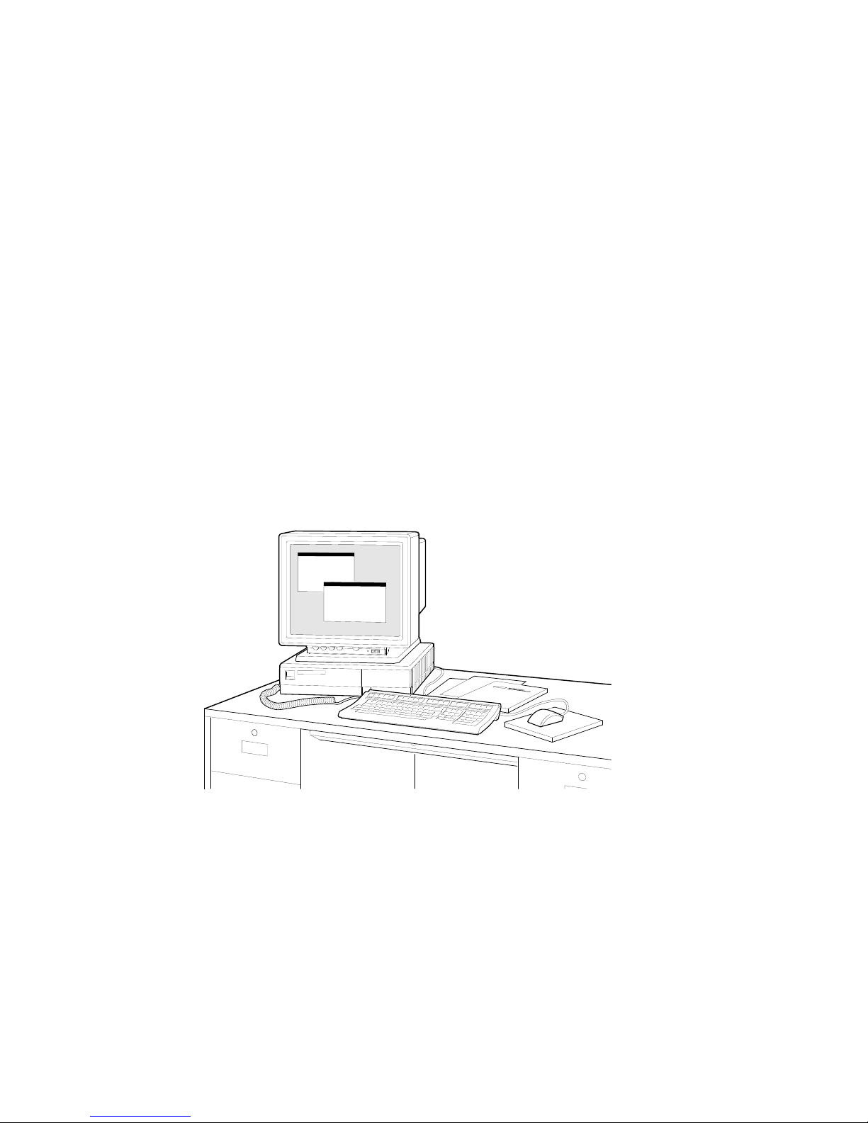
Figure 1–1 shows a fully configured system.
Figure 1–1 Your VAXstation 4000 Model 90 System
MLO-008071
1–2 Your VAXstation 4000 Model 90 System

System Components
System Components
Components
Shipped
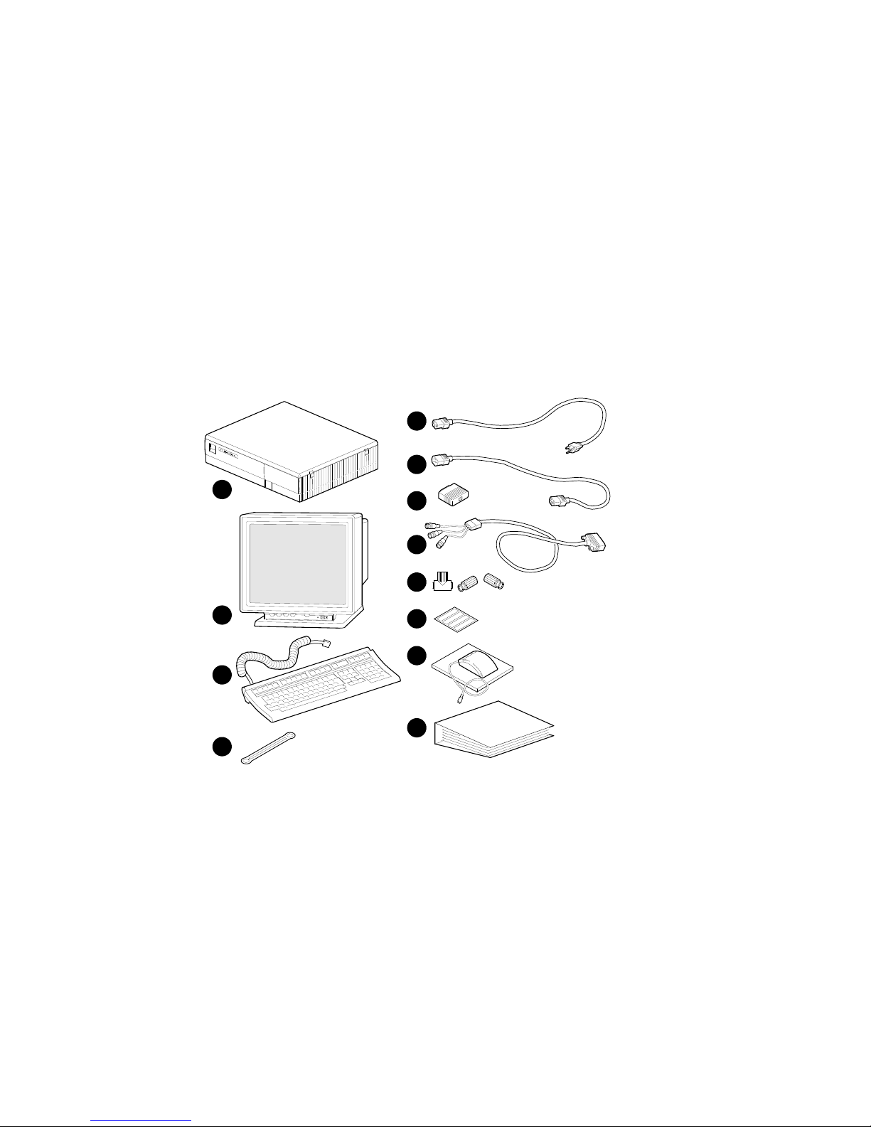
Listed below are the basic components of your system.
Figure 1–2 shows each component.
!
System unit
"
Monitor
#
Keyboard
$
Universal strain relief strap
%
System power cord
&
Monitor power cord
'
Loopback connector
(
Monitor video cable
)
One T-connector and two terminators
+>
Network label
+?
Mouse with mousepad
+@
Documentation
Your VAXstation 4000 Model 90 System 1–3
System Components
System
Components
Figure 1–2 shows all the basic components of your system.
Figure 1–2 System Components
5
6
1
2
3
4
7
8
9
10
11
12
MLO-008074
1–4 Your VAXstation 4000 Model 90 System
System Components
Front of
System Unit
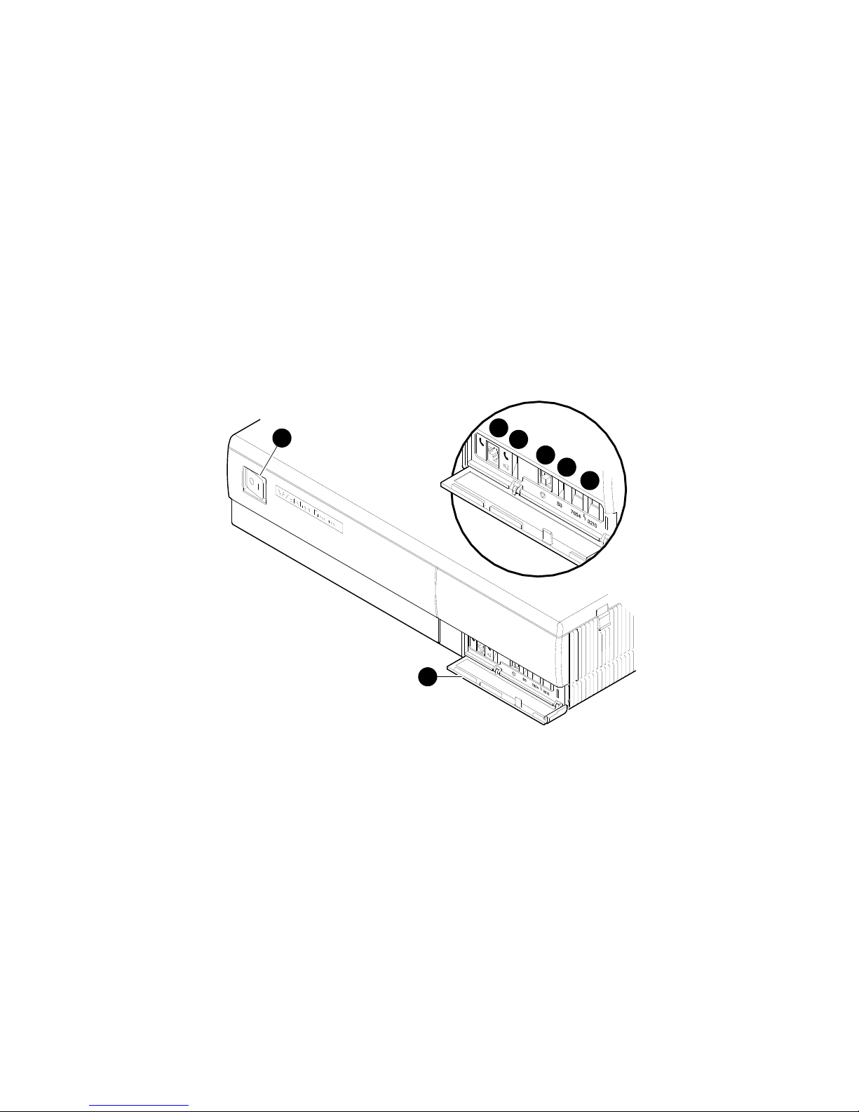
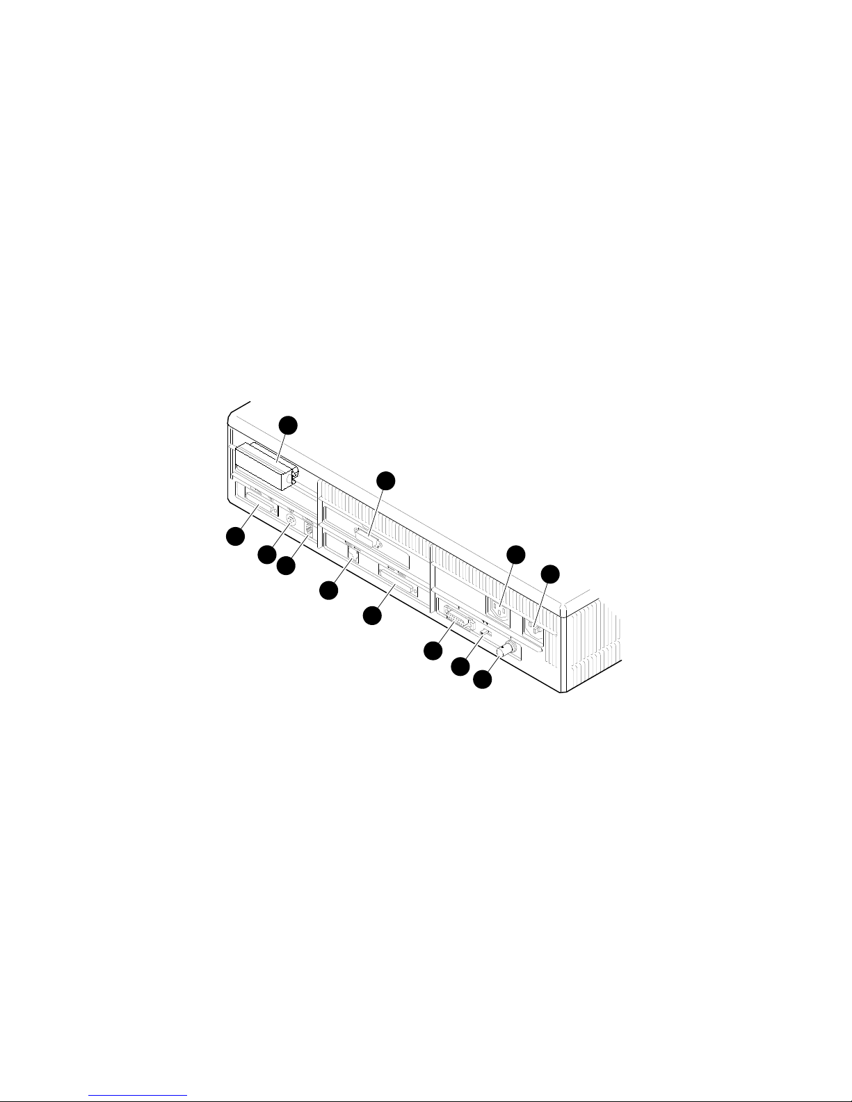
Figure 1–3 shows the ports, switches, and indicators on the front
of the system unit. Table 1–1 explains the function of each.
Figure 1–3 Front of System Unit
1
2
3
4
5
6
7
MLO-008072
Your VAXstation 4000 Model 90 System 1–5
System Components
Front
Components
Table 1–1 describes the ports, switches, and indicators on the
front of the system unit.
Table 1–1 Components: Front of System Unit
Number Feature Function
!
"
#
$
%
&
'
On/Off switch Power switch for system unit
Front door Protects switches.
Headset jack For audio output to
Audio speaker switch Turns speaker on (down) and
Halt button Used to put the system into
Alternate console
switch
Diagnostic lights Show status of the system
(shown in Figure 1–3 in off
(O) position).
a headset. (software
controlled)
off (up).
console mode.
Set to the up position to
select a terminal as an
alternate console for testing
purposes, or to the down
position to return to normal
use of the workstation
monitor.
during diagnostic tests. (See
Chapter 5.)
1–6 Your VAXstation 4000 Model 90 System
System Components
Back of System
Unit
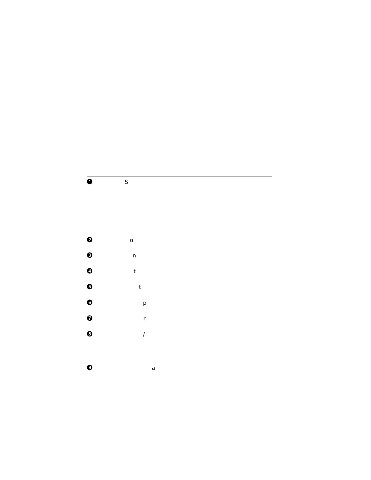
Figure 1–4 shows the ports, switches, and indicators on the back
of the system unit. Table 1–2 explains the function of each.
Figure 1–4 Back of System Unit
1
2
5
6
7
8
9
10
11
3
4
12
MLO-008073
Your VAXstation 4000 Model 90 System 1–7
System Components
Component
Descriptions
Table 1–2 describes the ports, switches, and indicators on the
back of the system unit.
Table 1–2 Components: Back of System Unit
Number Feature Function
!
"
#
$
%
&
'
(
)
SCSI port Used to connect Small
Monitor video port Used to connect the monitor
Monitor power port Used to connect the monitor
System power port Used to connect the system unit
Remote mouse/
keyboard port
Mouse port Used to connect the mouse
Keyboard port Used to connect the keyboard
Printer/
communications port
(TTA3)
Communications/
printer port (TTA2)
Computer System Interface
(SCSI) peripheral devices to
the system unit. Your system
comes with a SCSI terminator
pre-installed. Remove this
terminator if you attach
external options to the system
unit or expansion boxes.
video cable.
power cord.
power cord.
Used to connect the remote
mouse and keyboard cable.
cable.
cable.
Used primarily to connect a
printer or hardcopy terminal
through an RS423 cable.
OpenVMS does not support
modems on this port.
Used primarily to connect an
asynchronous communications
device such as a modem,
through an RS232 cable. The
secondary use is to attach a
printer or hardcopy terminal.
1–8 Your VAXstation 4000 Model 90 System
(continued on next page)
System Components
Table 1–2 (Cont.) Components: Back of System Unit
Number Feature Function
+>
+?
+@
Available Options
Options
Table 1–3 lists the internal and external options for the
VAXstation 4000 Model 90. Internal options must be installed
inside the system unit or in an expansion box. External options,
including the BA46 storage expansion box and peripheral
devices, such as printers and modems, can be attached by a cable
to the system unit.
Standard Ethernet
port
Network switch Used to select ThinWire
ThinWire Ethernet
port
Used to connect to a standard
Ethernet network.
Ethernet or standard Ethernet
networking options. Move the
switch to the left for standard
Ethernet or right for ThinWire
Ethernet.
Used to connect to a ThinWire
Ethernet network.
Your VAXstation 4000 Model 90 System 1–9

Available Options
An ‘‘X’’ in Table 1–3 indicates that the option can be installed in
either the system unit or an expansion box.
Table 1–3 VAXstation 4000 Devices and Options
Option
RZ23L, RZ24, RZ24L, RZ25 fixed disk drives X
RZ56, RZ57, RZ58 fixed disk drives X
RX26 diskette drive X
RRD42 compact disc drive X X
TZK10 cartridge tape drive X X
TLZ06 (RDAT) cassette tape drive X X
TZ30 tape drive X
MS44L-AA or MS44-CA memory modules X
TURBOchannel option X
DSW21 synchronous communications adapter X
LCSPX 8-plane graphics board X
SPXg 8-plane high-resolution color board X
SPXgt 24-plane high-resolution board X
System
Unit
Expansion
Box
1–10 Your VAXstation 4000 Model 90 System

Available Options
External options for the VAXstation 4000 Model 90 include:
• Button box (programmable function keyboard)
• Dial box
• Floor stand
• Headset
• Multiple-box rack
• Printer
• Remote cable option
• Tablet
Ordering
Options
Installing
Options
Contact your Digital sales representative for more information
about ordering any of these options.
To install options in the system unit, refer to the VAXstation
4000 Options Installation Guide.
To install options in the BA46 expansion box, refer to the BA46
Storage Expansion Box Owner’s Guide, which is shipped with the
expansion box.
Your VAXstation 4000 Model 90 System 1–11


2
Installing Your VAXstation 4000
Introduction
Chapter Topics
This chapter explains how to install the standalone system, run
system start-up tests, and record information about your system.
This chapter covers the following topics:
• Installing Your System
• Putting Your System in Console Mode
• Recording Information About Your System
Installing Your VAXstation 4000 2–1
Installing Your System
Installing Your System
Installation
Overview
Assemble the
T-connector
Table 2–1 lists the steps you take to install your VAXstation
4000 Model 90 system. The remaining pages in this section
explain and illustrate these steps in detail.
Table 2–1 Installation Steps for Your VAXstation 4000 Model
90 System
1. Connect the loopback and T-connector to the system
unit.
2. Connect the mouse and keyboard to the system unit.
3. Attach the monitor cable to the system unit and the
back of the monitor.
4. Attach the monitor power cable to the system unit and
the back of the monitor.
5. Connect the system power cord to the system unit and a
power outlet.
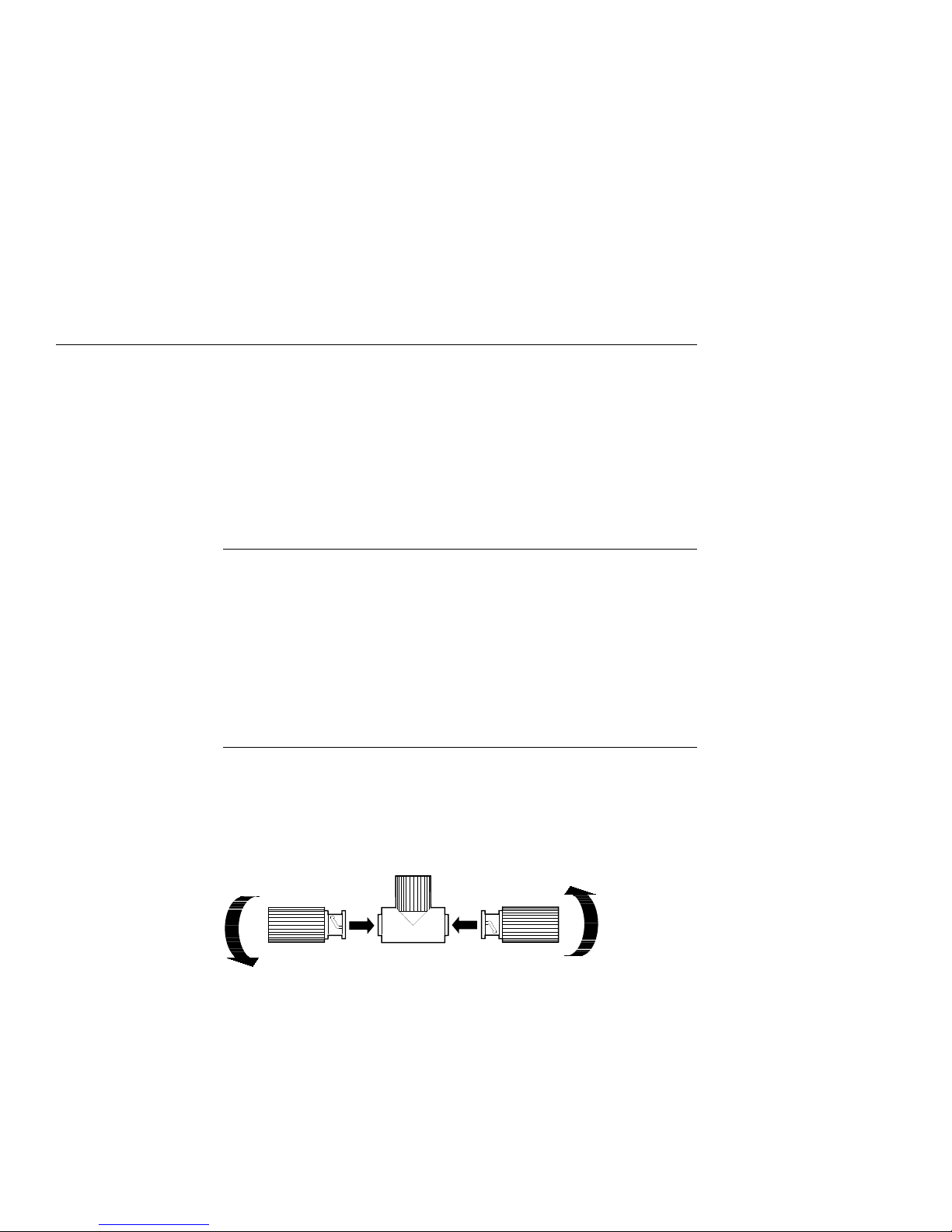
Follow the arrows in Figure 2–1 to assemble the T-connector.
Figure 2–1 Assembling the T-connector
2–2 Installing Your VAXstation 4000
MLO-008076
Installing Your System
Attach the
Loopback and
T-connector
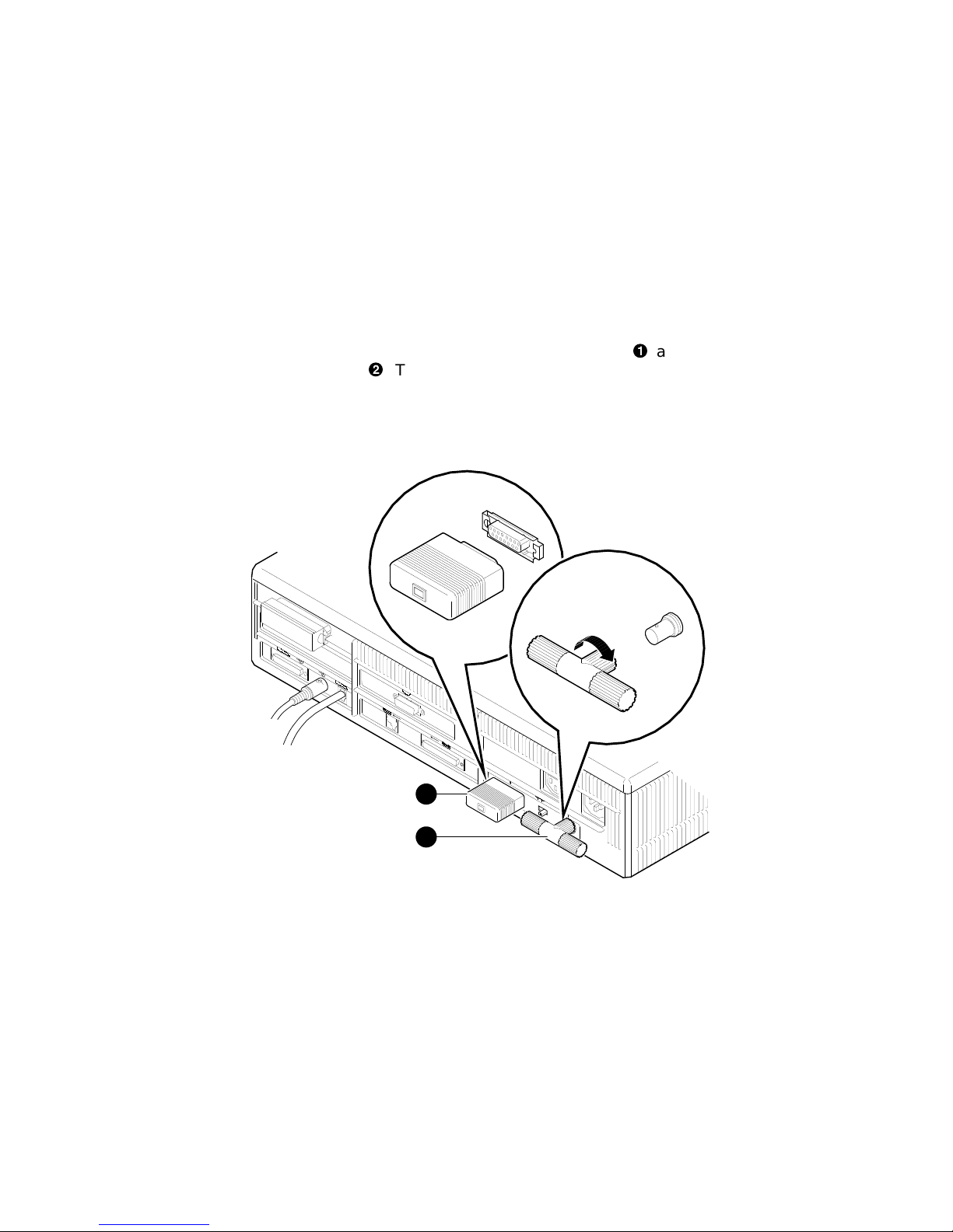
Follow Figure 2–2 to attach the loopback connector!and
the T-connector". Turn the T-connector to the right after you
connect it to the system unit.
Figure 2–2 Attaching the Loopback and T-connector
1
2
MLO-008077
Installing Your VAXstation 4000 2–3
Installing Your System
Connect the
Mouse and
Keyboard
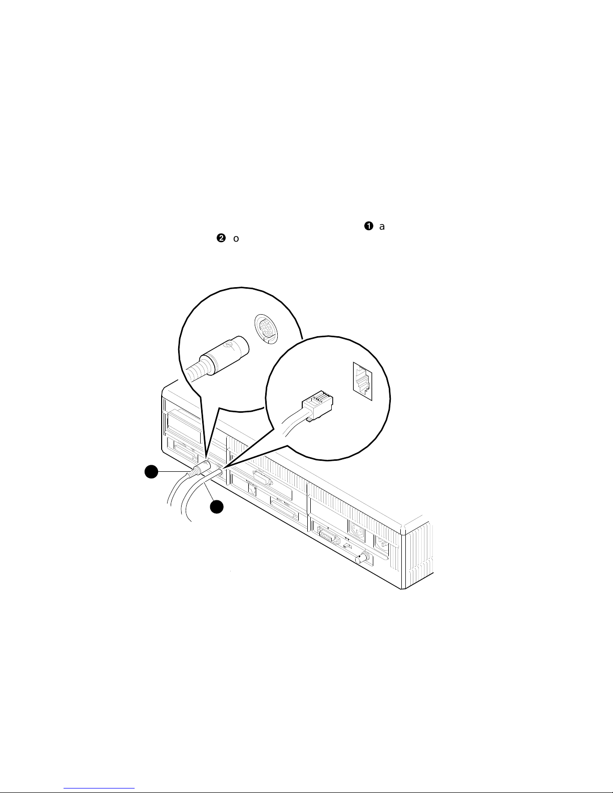
Follow Figure 2–3 to connect the mouse cable!and the
keyboard cable"to the system unit.
Figure 2–3 Connecting the Mouse and Keyboard
1
2
2–4 Installing Your VAXstation 4000
MLO-008075
Installing Your System
Attach the
Monitor Cables
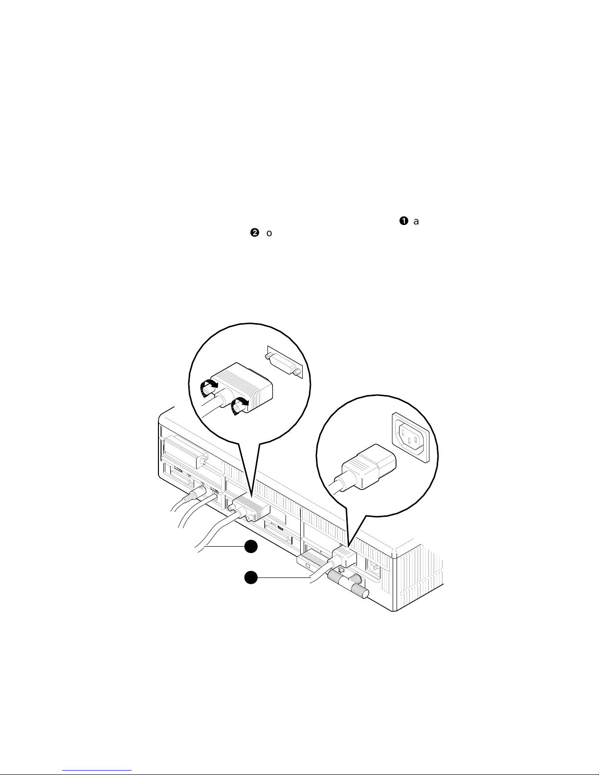
Follow Figure 2–4 to attach the monitor video cable!and the
monitor power cord"to the system unit. Make sure you align
the connectors in the monitor video cable; the alignment for the
LCSPX connector is opposite of the alignment for the SPXg and
SPXgt connectors.
Figure 2–4 Attaching the Monitor Cable
Recommended
Power Source
Digital recommends the system unit as the power source for the
monitor power cable. If you need a longer cable, order the remote
cable kit, described in the VAXstation 4000 Options Installation
Guide.
1
2
MLO-008078
Installing Your VAXstation 4000 2–5
Installing Your System
Universal Strain
Relief Strap
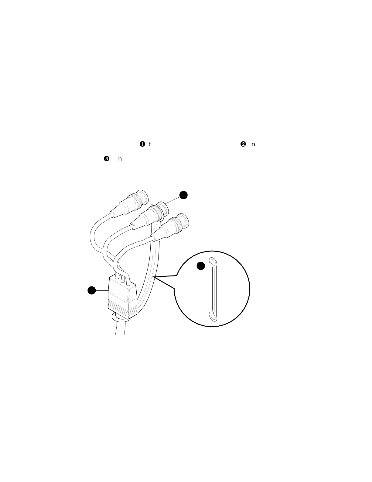
Follow Figure 2–5 to attach the notched end of the universal
strain relief strap!to the green (G) BNC connector"on the
monitor video cable, and the other end under the cable junction
block#. This strap reduces strain on the video cables.
Figure 2–5 Attaching the Universal Strain Relief Strap
R
G
3
2
B
1
2–6 Installing Your VAXstation 4000
MLO-008079
 Loading...