

Digital Equipment VAXstation 3100 Series, VAXstation 4000 Model 60, VAXstation 4000 Model 90 Upgrade Manual

Order Number: EK-VX463-IN. A01
VAXstation3100Family
toVAXstation4000Model60/90
UpgradeGuide

July, 1993
The information in this document is subject to change without notice and
should not be construed as a commitment by Digital Equipment Corporation.
Digital Equipment Corporation assumes no responsibility for any errors that
may appear in this document.
The software described in this document is furnished under a license and may
be used or copied only in accordance with the terms of such license.
No responsibility is assumed for the use or reliability of software on equipment
that is not supplied by Digital Equipment Corporation or its affiliated
companies.
Restricted Rights: Use, duplication, or disclosure by the U. S. Government is
subject to restrictions as set forth in subparagraph (c) (1) (ii) of the Rights in
Technical Data and Computer Software clause at DFARS 252.227–7013.
© Digital Equipment Corporation 1993.
The following are trademarks of Digital Equipment Corporation: DEC, VAX,
VAX DOCUMENT, VAXstation, VMS, and the Digital logo.
S2322
This document was prepared using VAX DOCUMENT, Version 2.1.

Contents
Preface . . . . . . . . . . . . . . . . . . . . . . . . . . . . . . . . . . . . . . . . . . . . . . . . . . . . . vii
1 Preparing for the System Upgrade
Upgrading Your Options to the VAXstation 4000 . . . . . . . . . . . . 1–1
Recording VAXstation 3100 System Information . . . . . . . . . . . . . 1–4
Shut Down the Software . . . . . . . . . . . . . . . . . . . . . . . . . . . . 1–4
Enter the SHOW DEVICE Command . . . . . . . . . . . . . . . . . . 1–4
Removing the System Unit Cover . . . . . . . . . . . . . . . . . . . . . . . . 1–6
Turn Off the System . . . . . . . . . . . . . . . . . . . . . . . . . . . . . . . 1–6
Disconnect the Cables . . . . . . . . . . . . . . . . . . . . . . . . . . . . . . 1–6
Remove the Cover . . . . . . . . . . . . . . . . . . . . . . . . . . . . . . . . . 1–7
Protecting Against Static Discharge . . . . . . . . . . . . . . . . . . . . . . 1–8
Checking the VAXstation 3100 Model Number . . . . . . . . . . . . . . 1–9
2 Removing Options from a Model 30 and 38 Workstation
Purpose . . . . . . . . . . . . . . . . . . . . . . . . . . . . . . . . . . . . . . . . . 2–1
Chapter Content . . . . . . . . . . . . . . . . . . . . . . . . . . . . . . . . . . 2–1
Removing Fixed Disk Drives . . . . . . . . . . . . . . . . . . . . . . . . . . . . 2–2
Typical Drive Plate Layout . . . . . . . . . . . . . . . . . . . . . . . . . . 2–2
Remove RZ2x Disk Drives . . . . . . . . . . . . . . . . . . . . . . . . . . . 2–3
Remove the Mass Storage Controller . . . . . . . . . . . . . . . . . . . 2–5
Remove the Drive Plate . . . . . . . . . . . . . . . . . . . . . . . . . . . . . 2–7
Removing the Ethernet ROM . . . . . . . . . . . . . . . . . . . . . . . . . . . 2–9
Remove the Scanline Coprocessor . . . . . . . . . . . . . . . . . . . . . 2–9
Remove the Ethernet ROM . . . . . . . . . . . . . . . . . . . . . . . . . . 2–12
iii

3 Removing Options from a Model 40 and 48 Workstation
Purpose . . . . . . . . . . . . . . . . . . . . . . . . . . . . . . . . . . . . . . . . . 3–1
Chapter Content . . . . . . . . . . . . . . . . . . . . . . . . . . . . . . . . . . 3–1
Removing Fixed Disk Drives . . . . . . . . . . . . . . . . . . . . . . . . . . . . 3–2
Typical Drive Plate Layout . . . . . . . . . . . . . . . . . . . . . . . . . . 3–2
Remove the Upper Drive Plate . . . . . . . . . . . . . . . . . . . . . . . . 3–4
Remove RZ2x Disk Drives . . . . . . . . . . . . . . . . . . . . . . . . . . . 3–6
Removing the Ethernet ROM . . . . . . . . . . . . . . . . . . . . . . . . . . . 3–8
Remove the Lower Drive Plate . . . . . . . . . . . . . . . . . . . . . . . . 3–8
Remove the Scanline Coprocessor . . . . . . . . . . . . . . . . . . . . . 3–11
Remove the Ethernet ROM . . . . . . . . . . . . . . . . . . . . . . . . . . 3–14
4 Removing Options from a Model 76 Workstation
Purpose . . . . . . . . . . . . . . . . . . . . . . . . . . . . . . . . . . . . . . . . . 4–1
Chapter Content . . . . . . . . . . . . . . . . . . . . . . . . . . . . . . . . . . 4–1
Removing Fixed Disk Drives . . . . . . . . . . . . . . . . . . . . . . . . . . . . 4–2
Typical Drive Plate Layout . . . . . . . . . . . . . . . . . . . . . . . . . . 4–2
Remove the Drive Plate . . . . . . . . . . . . . . . . . . . . . . . . . . . . . 4–3
Remove RZ2x Disk Drives . . . . . . . . . . . . . . . . . . . . . . . . . . . 4–5
Removing Memory Modules . . . . . . . . . . . . . . . . . . . . . . . . . . . . 4–7
Memory Configurations . . . . . . . . . . . . . . . . . . . . . . . . . . . . . 4–7
Remove the Modules . . . . . . . . . . . . . . . . . . . . . . . . . . . . . . . 4–7
Removing the Ethernet ROM . . . . . . . . . . . . . . . . . . . . . . . . . . . 4–9
Remove the Scanline Coprocessor . . . . . . . . . . . . . . . . . . . . . 4–9
Remove the Ethernet ROM . . . . . . . . . . . . . . . . . . . . . . . . . . 4–12
5 Completing the System Upgrade
Preparing the VAXstation 4000 System . . . . . . . . . . . . . . . . . . . 5–1
Unpack the New System . . . . . . . . . . . . . . . . . . . . . . . . . . . . 5–1
Remove the System Unit Cover . . . . . . . . . . . . . . . . . . . . . . . 5–2
Installing Options in the VAXstation 4000 System . . . . . . . . . . . 5–3
Ethernet ROM . . . . . . . . . . . . . . . . . . . . . . . . . . . . . . . . . . . . 5–3
Install the Memory Modules . . . . . . . . . . . . . . . . . . . . . . . . . 5–4
Install Disk Drives . . . . . . . . . . . . . . . . . . . . . . . . . . . . . . . . . 5–4
Installing the VAXstation 4000 System . . . . . . . . . . . . . . . . . . . . 5–5
Set Up the System . . . . . . . . . . . . . . . . . . . . . . . . . . . . . . . . . 5–5
Test Installation . . . . . . . . . . . . . . . . . . . . . . . . . . . . . . . . . . . 5–5
Returning the VAXstation 3100 System to Digital . . . . . . . . . . . 5–5
Pack the System . . . . . . . . . . . . . . . . . . . . . . . . . . . . . . . . . . 5–5
Service Contract . . . . . . . . . . . . . . . . . . . . . . . . . . . . . . . . . . . 5–5
iv

Index
Figures
1–1 Typical Screen Display of a SHOW DEVICE Command . . . . . 1–5
1–2 Disconnecting the System Unit and Monitor Cables . . . . . . . 1–6
1–3 Removing the VAXstation 3100 System Unit Cover . . . . . . . . 1–7
1–4 Attaching the Antistatic Wrist Strap to the System Unit . . . . 1–8
2–1 Common Configuration for a Model 30 and 38 Drive
Plate . . . . . . . . . . . . . . . . . . . . . . . . . . . . . . . . . . . . . . . . . . . 2–2
2–2 Removing RZ2x Fixed Disk Drives from the Drive Plate . . . . 2–4
2–3 SCSI Mass Storage Controller Module Cables . . . . . . . . . . . . 2–5
2–4 Removing the SCSI Mass Storage Controller Module . . . . . . 2–6
2–5 Removing the Drive Plate from a Model 30 or 38 System . . . 2–8
2–6 Scanline Coprocessor Mounting Brackets . . . . . . . . . . . . . . . . 2–10
2–7 Removing the Scanline Coprocessor from the Model 30 and
38 System . . . . . . . . . . . . . . . . . . . . . . . . . . . . . . . . . . . . . . . 2–11
2–8 Removing the Ethernet ROM from the Model 30 and 38
System . . . . . . . . . . . . . . . . . . . . . . . . . . . . . . . . . . . . . . . . . . 2–12
3–1 Common Configuration for a Model 40 and 48 Drive
Plate . . . . . . . . . . . . . . . . . . . . . . . . . . . . . . . . . . . . . . . . . . . 3–3
3–2 Disconnecting the SCSI and Power Cables . . . . . . . . . . . . . . 3–5
3–3 Removing the Upper Drive Plate from the Model 40 and 48
System . . . . . . . . . . . . . . . . . . . . . . . . . . . . . . . . . . . . . . . . . . 3–6
3–4 Removing RZ2x Fixed Disks from the Drive Plate . . . . . . . . . 3–7
3–5 Lower Drive Plate Configuration . . . . . . . . . . . . . . . . . . . . . . 3–9
3–6 Removing the Lower Drive Plate . . . . . . . . . . . . . . . . . . . . . . 3–10
3–7 Scanline Coprocessor Mounting Brackets . . . . . . . . . . . . . . . . 3–12
3–8 Removing the Scanline Coprocessor from the Model 40 and
48 System . . . . . . . . . . . . . . . . . . . . . . . . . . . . . . . . . . . . . . . 3–13
3–9 Removing the Ethernet ROM from the Model 40 and 48
System . . . . . . . . . . . . . . . . . . . . . . . . . . . . . . . . . . . . . . . . . . 3–14
4–1 Common Configuration of the Model 76 Drive Plate . . . . . . . 4–2
4–2 Disconnecting the SCSI Signal and Power Cables . . . . . . . . . 4–4
4–3 Removing RZ2x Fixed Disks from the Drive Plate . . . . . . . . . 4–6
4–4 Removing Memory Boards from the Model 76 System . . . . . . 4–8
4–5 Scanline Coprocessor Mounting Brackets . . . . . . . . . . . . . . . . 4–10
v

4–6 Removing the Scanline Coprocessor from the Model 76
System . . . . . . . . . . . . . . . . . . . . . . . . . . . . . . . . . . . . . . . . . . 4–11
4–7 Removing the Ethernet ROM from the Model 76 System . . . 4–12
5–1 VAXstation 4000 Model 60/90 System Upgrade Kit . . . . . . . . 5–1
5–2 Removing the VAXstation 4000 System Unit Cover . . . . . . . . 5–2
5–3 Installing the Ethernet ROM in the VAXstation 4000
System . . . . . . . . . . . . . . . . . . . . . . . . . . . . . . . . . . . . . . . . . . 5–3
5–4 Attaching a Mounting Plate to a Disk Drive . . . . . . . . . . . . . 5–4
Tables
1–1 Options You Can Upgrade . . . . . . . . . . . . . . . . . . . . . . . . . . . 1–1
1–2 Model Numbers of VAXstation 3100 Family Systems . . . . . . . 1–9
vi

Preface
Purpose of this
Guide
Who Should
Use This Guide
This guide describes how to upgrade the VAXstation 3100 family
of systems to a VAXstation 4000 Model 60 or Model 90 only. The
VAXstation 3100 family consists of five models–30, 38, 40, 48,
and 76.
You perform the upgrade by removing supported options from
the VAXstation 3100 system unit and installing them in the
VAXstation 4000 system unit. The upgrade information includes
how to remove and install RZ2x disk drives, Ethernet ROMs,
memory modules, and execute some console commands.
This guide also describes how to repackage the VAXstation 3100
system for shipment back to Digital after completing the system
upgrade.
Only a Digital service representative or qualified self–
maintenance customer should perform this upgrade. You must
have a working knowledge of and experience working on the
internal hardware devices of a VAXstation 3100 system. If
you are not qualified to perform this upgrade, call your Digital
service representative to schedule an upgrade.
Note
It is the customer’s responsibility to perform software
backups of the system and user disks. The backups
should be performed before the Digital service
representative arrives at the site. Backups are
mandatory to ensure that data is not lost during the
upgrade.
vii

Structure of
this Guide
The guide contains five chapters, as follows:
Chapter Content
1 Options you can upgrade; preparing the VAXstation
3100 system.
2 Removing options from the Model 30 and 38.
3 Removing options from the Model 40 and 48.
4 Removing options from the Model 76.
5 Installing the VAXstation 4000 system; returning the
VAXstation 3100 system.
Conventions
Used in this
Guide
The following conventions are used in this guide:
Convention Meaning
Return
italic type Italic type emphasizes important
UPPERCASE Words in uppercase indicate a command.
RZ2x A lowercase italic x indicates a variable
CAUTION Cautions indicate information that prevents
NOTE Notes provide general information about the
A key name enclosed in a box indicates that
you press that key.
information, indicates variables, and
indicates complete titles of manuals.
model number.
damage to equipment or software. Read
cautions carefully.
current topic.
viii

Preparing for the System Upgrade
Upgrading Your Options to the VAXstation 4000
Table 1–1 lists the options you can move from a VAXstation 3100
system to a VAXstation 4000 system.
Table 1–1 Options You Can Upgrade
Monitors: Comments:
VR262-Ax 60 Hz (Supported on Model 60 only)
VR290-Dx 60 Hz (Supported on Model 60 only)
VR297-Dx 60 Hz (Supported on Model 60 only)
VR299-Dx 60 Hz (Supported on Model 60 only)
VR319-Cx 66 Hz
VR319-Dx 72 Hz
VR320-Cx 66 Hz
VR320-Dx 72 Hz
VRC16-Cx 72 Hz
VRM17-Ax 72 Hz
VRT13-Dx 60 Hz (Supported on Model 60 only)
VRT16-Dx 66 Hz
VRT16-Hx 66/72 Hz
VRT19-Dx 66 Hz
1
(continued on next page)
Preparing for the System Upgrade 1–1

Upgrading Your Options to the VAXstation 4000
Table 1–1 (Cont.) Options You Can Upgrade
Monitors: Comments:
VRT19-Hx 66/72 Hz
Fixed Disk Drives: Comments:
RZ23L
RZ24
RZ24L
RZ25
RZ55 Supported on expansion box only
RZ56 Supported on expansion box only
RZ57 Supported on expansion box only
RZ58 Supported on expansion box only
Removable-Media
Drives: Comments:
RRD42 Supported on expansion box/tabletop
TLZ04 Supported on expansion box/tabletop
TLZ06 Supported on expansion box/tabletop
TZ30 Supported on expansion box only
TZK10 Supported on expansion box only
Memory:
MS44-AA
MS44L-Bx
1–2 Preparing for the System Upgrade
only
only
only
(continued on next page)

Upgrading Your Options to the VAXstation 4000
Table 1–1 (Cont.) Options You Can Upgrade
Input Devices: Comments:
LK401-xx Keyboard
VSXXX-AA/GA Mouse
VSXXX-AB Tablet
Expansion Boxes:
SZ03
SZ12
SZ16
RZ5X
Graphics
You cannot upgrade the graphics module from your
VAXstation 3100 system to the VAXstation 4000 system.
Preparing for the System Upgrade 1–3

Recording VAXstation 3100 System Information
Recording VAXstation 3100 System Information
Shut Down the
Software
Enter the
SHOW DEVICE
Command
Refer to the VMS Installation and Operations Manual for the
proper operating system shutdown procedure.
Before you begin the upgrade you need to record the system
Ethernet address (only if you are moving the Ethernet ROM to
the new system) and the SCSI ID settings on your disk drives.
Follow these steps and refer to Figure 1–1:
1. Press the Halt button on the rear of the system unit.
Result:
screen.
2. Enter the SHOW DEVICE command at the console prompt
and press
3. Record the system Ethernet address (if applicable).
4. Record the SCSI ID number for each drive.
The system displays the console prompt (>>>) on the
Return
.
1–4 Preparing for the System Upgrade
Recording VAXstation 3100 System Information
Figure 1–1 Typical Screen Display of a SHOW DEVICE Command
>>> SHOW DEVICE
Ethernet Hardware
Address
Device Name
SCSI Bus
SCSI ID Setting
Device Type
VMS/VMB ADDR DEVTYP NUMBYTES RM/FX WP DEVNAM REV
------- ---- ------ -------- ----- -- ------ --ESAO 08-00-2B-07-E3-83
DKA300 A/3/0 DISK 121.64 MB FX RZ23L xxxx
MKA500 A/5/0 TAPE ....... RM WP
..HostID.. A/6 INITR
DKA200 A/2/0 DISK 121.64 MB FX RZ23L xxxx
DKA400 A/4/0 RODISK 205.12 MB RM WP RRD42 xxxx
>>>
MLO-010942
Preparing for the System Upgrade 1–5
Removing the System Unit Cover
Removing the System Unit Cover
Turn Off the
System
After shutting down the operating system and recording
the VAXstation 3100 system information, turn the system
peripherals off in the following order:
1. Expansion boxes
2. Printer, modem, and other equipment
3. Monitor
4. System unit
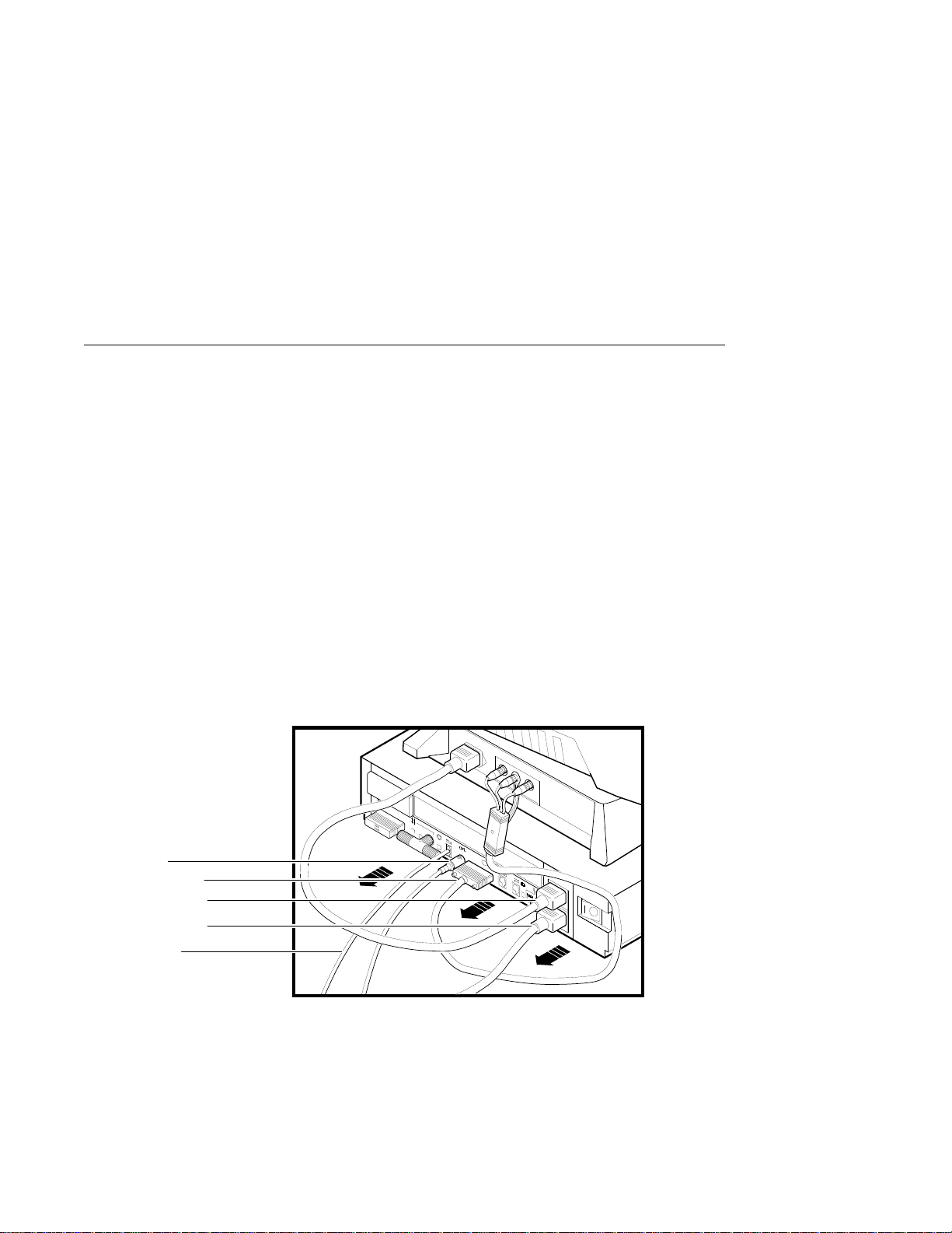
Disconnect the
Cables
Disconnect the cables shown in Figure 1–2 from the back of the
system unit.
Figure 1–2 Disconnecting the System Unit and Monitor Cables
Mouse Cable
Monitor Video Cable
Monitor Power Cord
System Power Cord
Keyboard Cable
1–6 Preparing for the System Upgrade
MLO-010907
Removing the System Unit Cover
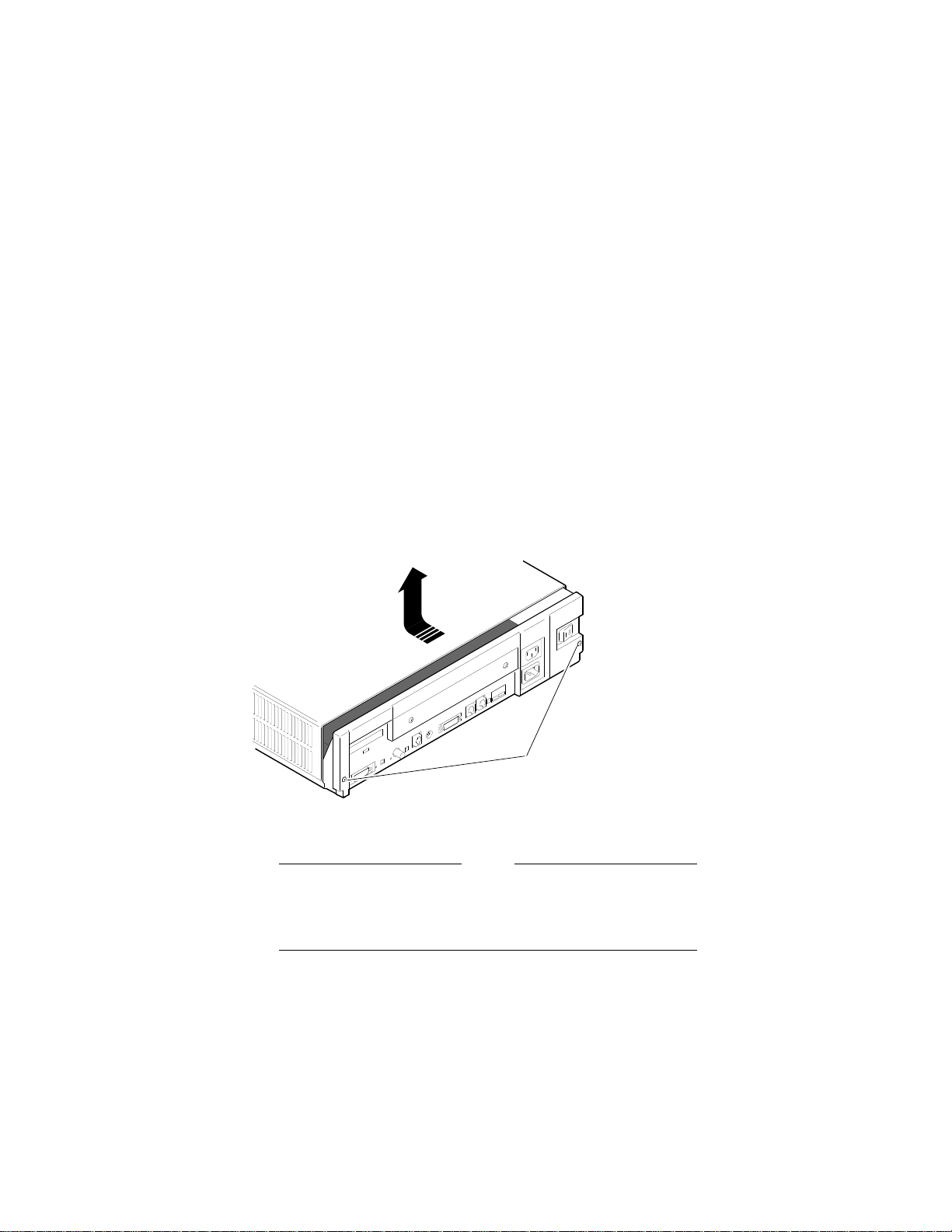
Remove the
Cover
To remove the system unit cover from the VAXstation 3100
workstation, do the following and refer to Figure 1–3:
1. Using a Phillips screwdriver, loosen the two captive screws
at the back of the system unit on the outside edges. Do not
remove the screws.
2. Slide the cover towards the front of the system and lift it up
and away from the system unit.
Figure 1–3 Removing the VAXstation 3100 System Unit Cover
Screws
MLO-010841
3. Place the cover aside for use later during repackaging.
Note
The height of the system unit enclosure is different for
some of the VAXstation 3100 models, but the procedure
for removing the cover is the same.
Preparing for the System Upgrade 1–7

Protecting Against Static Discharge
Protecting Against Static Discharge
Caution:
To eliminate any static charge that you may have built
up, touch the top of the power supply in the system unit.
This discharges any static electricity.
Always wear an antistatic wrist strap when working inside the
system unit to avoid damage caused by static discharge. Attach
the wrist strap as shown in Figure 1–4.
Figure 1–4 Attaching the Antistatic Wrist Strap to the System Unit
Power Supply
Alligator Clip
System Unit Frame
Antistatic Wrist Strap
1–8 Preparing for the System Upgrade
MLO-005484

Checking the VAXstation 3100 Model Number
Checking the VAXstation 3100 Model Number
After you have disconnected the cables and before beginning
the upgrade, check the model number of the system you are
upgrading.
Each system has a model code number stamped on the rear of
the system unit. Look at the label and refer to the next table to
determine which chapter to use for the upgrade procedures.
Table 1–2 Model Numbers of VAXstation 3100 Family Systems
Model Code
Number
VS42A-xx Model 30 Chapter 2
WS42A-xx Model 38 Chapter 2
VS42S-xx Model 40 Chapter 3
WS42B-xx Model 48 Chapter 3
WS43A-xx Model 76 Chapter 4
1
VAXstation 3100 System Go To:
1
xx: variable extensions
Preparing for the System Upgrade 1–9


2
Removing Options from a Model 30 and 38
Workstation
Purpose
Chapter
Content
The purpose of this chapter is to provide upgrade information so
that a Digital service representative or knowledgeable Digital
customer can upgrade an existing VAXstation 3100 Model 30 or
38 workstation to a VAXstation 4000 Model 60 or 90 workstation.
Caution:
Only a Digital service representative or qualified
self–maintenance customer should perform this
upgrade. You must have a working knowledge of and
experience working on the internal hardware devices
of a VAXstation 3100 system. If you are not qualified
to perform this upgrade, call your Digital service
representative to schedule an upgrade.
This chapter describes how to remove options from a Model
30 and Model 38 workstation. These two models are very
similar in structure. When there are differences in the upgrade
instructions they are called out with a Note specifying the
differences between the two models. This chapter contains the
following information:
• Removing Fixed Disk Drives
• Removing the Ethernet ROM
Removing Options from a Model 30 and 38 Workstation 2–1
Removing Fixed Disk Drives
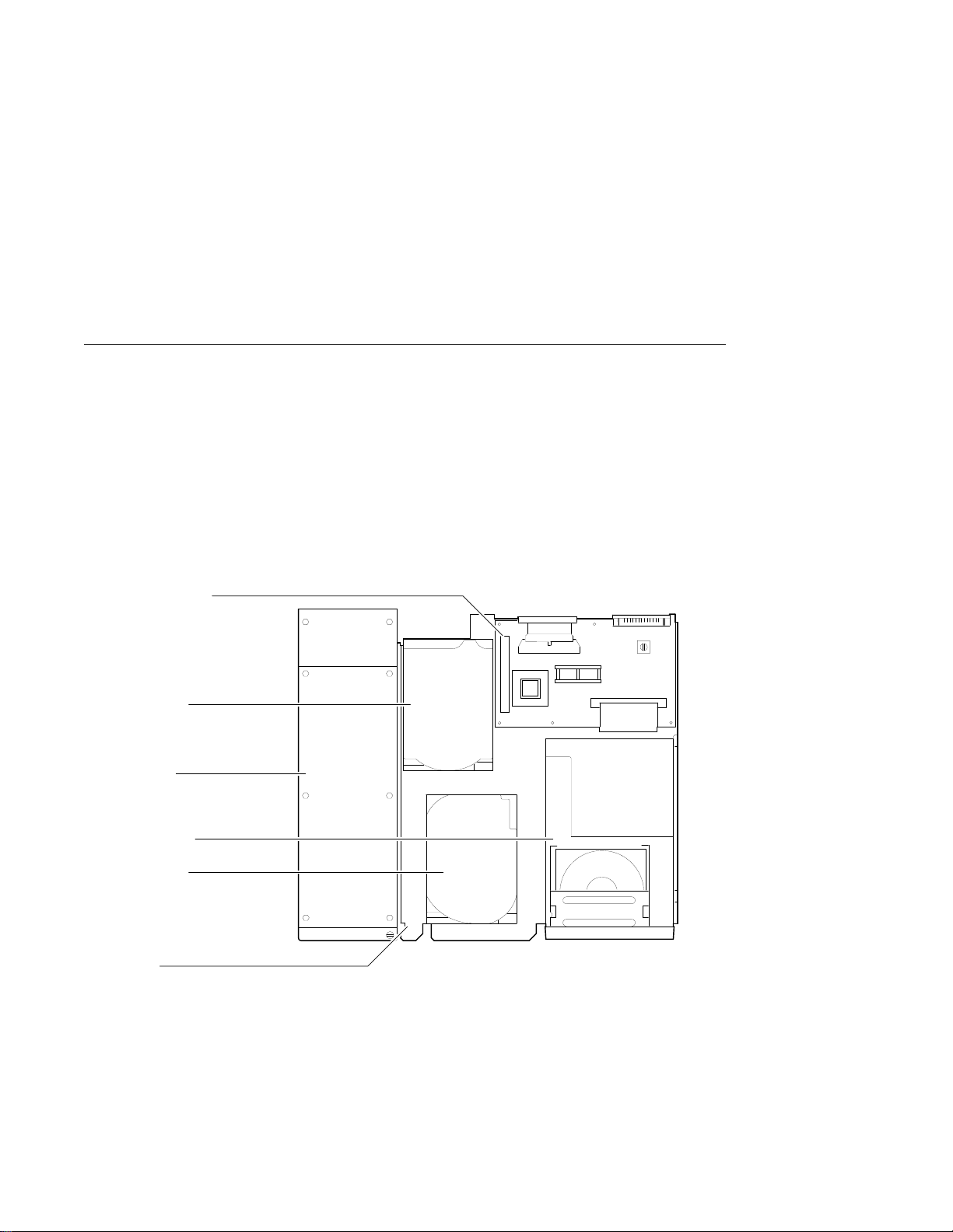
Removing Fixed Disk Drives
Typical Drive
Plate Layout
There are several possible drive plate configurations for the
Model 30 and 38, including two different types of drive plates.
There are also different kinds of SCSI mass storage controllers
depending on the model you are upgrading. Figure 2–1 shows a
common configuration of a Model 30 or 38 drive plate.
Figure 2–1 Common Configuration for a Model 30 and 38 Drive Plate
SCSI Mass Storage
Controller Module
RZxx Hard Disk
Power Supply
TZ30 Tape Drive
RZxx Hard Disk
System Rear
Drive Plate
2–2 Removing Options from a Model 30 and 38 Workstation
System Front
MLO-004579
 Loading...