

Digital Equipment VAXstation 3100, VAXstation 3100 30, VAXstation 3100 40 Upgrade Installation Manual

VAXstation3100Upgrade
InstallationGuide
Models30to38
Models40to48
Order Number EK-345AA-IN-002
digital equipment corporation
maynard, massachusetts

Second Edition, January 1990
The information in this document is subject to change without notice and should not
be construed as a commitment by Digital Equipment Corporation. Digital Equipment
Corporation assumes no responsibility for any errors that may appear in this document.
The software described in this document is furnished under a license and may be used or
copied only in accordance with the terms of such license.
No responsibility is assumed for the use or reliability of software on equipment that is not
supplied by Digital Equipment Corporation or its affiliated companies.
Restricted Rights: Use, duplication, or disclosure by the U. S. Government is subject to
restrictions as set forth in subparagraph ( c) (1 ) ( ii) of the Rights in Technical Data and
Computer Software clause at DFARS 252.227–7013.
Copyright © Digital Equipment Corporation 1990
All Rights Reserved.
Printed in U.S.A.
FCC NOTICE: The equipment described in this manual generates, uses, and may emit
radio frequency energy. The equipment has been type tested and found to comply with
the limits for a Class A computing device pursuant to Subpart J of Part 15 of FCC
Rules, which are designed to provide reasonable protection against such radio frequency
interference when operated in a commercial environment. Operation of this equipment in
a residential area may cause interference, in which case the user at his own expense may
be required to take measures to correct the interference.
The following are trademarks of Digital Equipment Corporation:
DEC DIBOL UNIBUS
DEC/CMS EduSystem VAX
DEC/MMS IAS VAXcluster
DECnet MASSBUS VMS
DECsystem–10 PDP VT
DECSYSTEM–20 PDT
DECUS RSTS
DECwriter RSX
This document was prepared and published by Educational Services Development and
Publishing, Digital Equipment Corporation.

Contents
About This Guide vii
1 Upgrading a Diskless Model 30
1.1 PV11U-AA Kit Contents . . . . . . . . . . . . . . . . . . . . . . . . . . . . . 1
1.2 Preparing the System for Installation . . . . . . . . . . . . . . . . . . 2
1.3 Installing the Modules . . . . . . . . . . . . . . . . . . . . . . . . . . . . . . 7
1.4 Replacing the Power Supply Screws . . . . . . . . . . . . . . . . . . . . 12
1.5 Installing the New Bezel Insert . . . . . . . . . . . . . . . . . . . . . . . 13
1.6 Installing the Upgrade Label . . . . . . . . . . . . . . . . . . . . . . . . . 15
1.7 Reinstalling the System Box Cover . . . . . . . . . . . . . . . . . . . . 15
1.8 Completing the Installation . . . . . . . . . . . . . . . . . . . . . . . . . . 15
2 Upgrading a Model 30 (No Diskette)
2.1 PV11U-CA Kit Contents . . . . . . . . . . . . . . . . . . . . . . . . . . . . . 16
2.2 Preparing the System for Installation . . . . . . . . . . . . . . . . . . 17
2.3 Installing the Modules . . . . . . . . . . . . . . . . . . . . . . . . . . . . . . 26
2.4 Installing the New Drive Plate . . . . . . . . . . . . . . . . . . . . . . . 31
2.5 Configuring the Drives on the New Drive Plate . . . . . . . . . . 33
2.6 Installing the RZ22/RZ23 Disk Drive(s) . . . . . . . . . . . . . . . . . 34
2.7 Installing the TZ30 Tape Drive . . . . . . . . . . . . . . . . . . . . . . . 38
2.8 Replacing the Power Supply Screws . . . . . . . . . . . . . . . . . . . . 43
2.9 Changing the Medallion . . . . . . . . . . . . . . . . . . . . . . . . . . . . . 44
2.10 Installing the Upgrade Label . . . . . . . . . . . . . . . . . . . . . . . . . 44
2.11 Reinstalling the System Box Cover . . . . . . . . . . . . . . . . . . . . 44
2.12 Completing the Installation . . . . . . . . . . . . . . . . . . . . . . . . . . 44
iii

iv Contents
3 Upgrading a Model 30 (With Diskette)
3.1 PV11U-BA Kit Contents . . . . . . . . . . . . . . . . . . . . . . . . . . . . . 45
3.2 Preparing the System for Installation . . . . . . . . . . . . . . . . . . 46
3.3 Installing the Modules . . . . . . . . . . . . . . . . . . . . . . . . . . . . . . 54
3.4 Installing the New Drive Plate . . . . . . . . . . . . . . . . . . . . . . . 59
3.5 Configuring the Drives on the New Drive Plate . . . . . . . . . . 61
3.6 Installing the RZ22/RZ23 Disk Drive(s) . . . . . . . . . . . . . . . . . 62
3.7 Installing the RX23 Diskette Drive . . . . . . . . . . . . . . . . . . . . 65
3.8 Replacing the Power Supply Screws . . . . . . . . . . . . . . . . . . . . 70
3.9 Installing the New Bezel Window . . . . . . . . . . . . . . . . . . . . . 71
3.10 Installing the Upgrade Label . . . . . . . . . . . . . . . . . . . . . . . . . 73
3.11 Reinstalling the System Box Cover . . . . . . . . . . . . . . . . . . . . 73
3.12 Completing the Installation . . . . . . . . . . . . . . . . . . . . . . . . . . 73
4 Upgrading the Model 40
4.1 PV15U-AA Kit Contents . . . . . . . . . . . . . . . . . . . . . . . . . . . . 74
4.2 Preparing the System for Installation . . . . . . . . . . . . . . . . . . 75
4.3 Installing the Modules . . . . . . . . . . . . . . . . . . . . . . . . . . . . . . 84
4.4 Replacing the MSC Module . . . . . . . . . . . . . . . . . . . . . . . . . . 93
4.5 Changing the Medallion . . . . . . . . . . . . . . . . . . . . . . . . . . . . . 93
4.6 Installing the Upgrade Label . . . . . . . . . . . . . . . . . . . . . . . . . 94
4.7 Reinstalling the System Box Cover . . . . . . . . . . . . . . . . . . . . 94
4.8 Completing the Installation . . . . . . . . . . . . . . . . . . . . . . . . . . 94
A Upgrade and Return Forms
Index

Contents v
Tables
1 Related Documents . . . . . . . . . . . . . . . . . . . . . . . . . . . . . . . . viii
3–1 RX23 SCSI ID Switch Settings . . . . . . . . . . . . . . . . . . . . . . . 66

AboutThisGuide
This installation guide describes how to install the upgrade options that
are available for the VAXstation 3100 systems. The upgrade is available
on both the model 30 and model 40 VAXstation 3100 systems. The
VAXstation system becomes a VAXstation 3100 system models 38 and 48
once the upgrade is complete.
Organization
There are four upgrade kits available. Each chapter describes how to
install one of the four kits.
Chapter Upgrade From To
1 A diskless VAXstation 3100 model
30 system
2 A VAXstation 3100 model 30
system without a diskette drive
3 A VAXstation 3100 model 30
system with a diskette drive
4 A VAXstation 3100 model 40
system
A diskless VAXstation
3100 model 38 system
A VAXstation 3100 model
38 system without a
diskette drive. This
system may or may not
contain a TZ30 tape drive.
A VAXstation 3100 model
38 system with a diskette
drive
A VAXstation 3100 model
48 system
Intended Audience
This document is only for Digital Customer Services personnel.
vii

viii About This Guide
Tools and Equipment
You need the following tools to service the VAXstation 3100 systems:
Tools and Equipment Part Number
Wrist strap and antistatic mat (included in Field Service
antistatic kit)
29-26246-00
Related Documents
You can order the following documents from Digital:
Table 1 Related Documents
Documents Order Number
VAXstation 3100 Maintenance Guide EK-285AA-MG
VAXstation 3100 Maintenance Guide Addendum EK-344AA-AD
Models 38 & 48
VAXstation 3100 Model 40 Customer Information Kit EK-VS310-IL
Managing your VAXstation 3100 Model 30 Standalone EK-260AA-OM
VAXstation 3100 Hardware Information Model 30 EK-265AA-OM
VAXstation 3100 Hardware Information Model 40 EK-266AA-OM
Using your VAXstation 3100 Model 30 Satellite EK-259AA-UG
VAXstation 2000, MicroVAX 2000, VAXmate Network Guide EK-NETAB-UG
Digital personnel may order the documents shown in Table 1 from:
Digital Equipment Corporation
444 Whitney Street
Northboro, MA 01532
Attn: Publishing and Circulation Services (NRO3/W3)
Order Processing Section

About This Guide ix
Conventions
This document uses the following conventions:
Convention Meaning
Note Provides general information
Caution Provides information to prevent damage to the
PN Part number
equipment

1
UpgradingaDisklessModel30
This chapter contains installation procedures for upgrading a diskless
VAXstation 3100 model 30 system to a diskless VAXstation 3100 model 38
system.
1.1 PV11U-AA Kit Contents
The following table lists the contents and part numbers of the PV11U-AA
kit:
Kit Item Part Number
Bezel insert for FCC shielding 74-37499-02
KA42-BA system module 54-19356-01
Owners manual, network guide, site planning
guide
VAXstation 3100 Upgrade Installation Guide EK-345AA-IN
Upgrade label 36-15946-01
Power supply caution label 36-20124-01
Medallion, VAXstation 3100 M 38
Three power supply safety screws
One screw is extra.
EK-VSM30-DK
12-30934-01
1

2 Upgrading a Diskless Model 30
1.2 Preparing the System for Installation
To prepare the system for installation:
Shut Down the System
1. Shut down the system software.
2. Run a self-test to verify the operation of the present configuration.
>>> TEST F 1
3. Turn the system power switch off.
Open the System Box
CAUTION
Wear a static wrist strap and use a static mat (PN 29-26242-00)
when replacing FRUs.

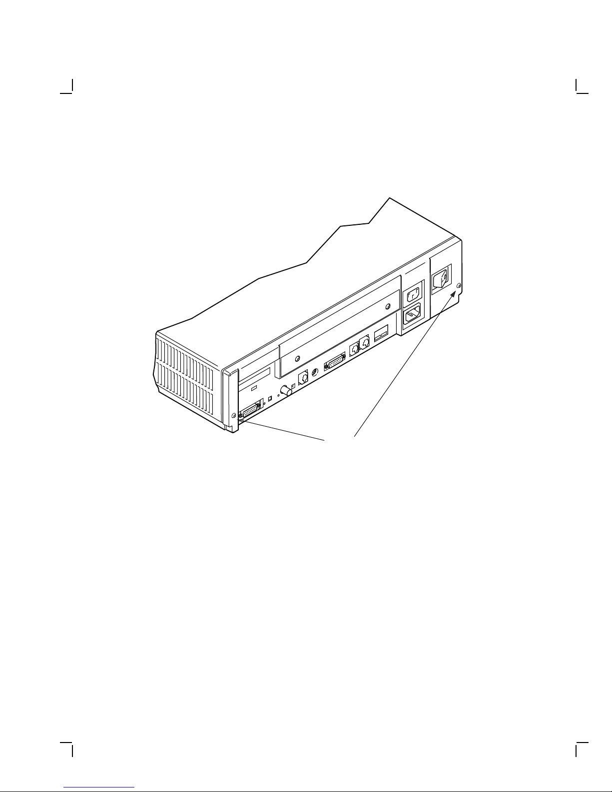
1. Unscrew the two cover screws.
Upgrading a Diskless Model 30 3
COVER
SCREW
LOCATIONS
2. Slide the cover forward and up off the system box.
MA-X0796-88
4 Upgrading a Diskless Model 30
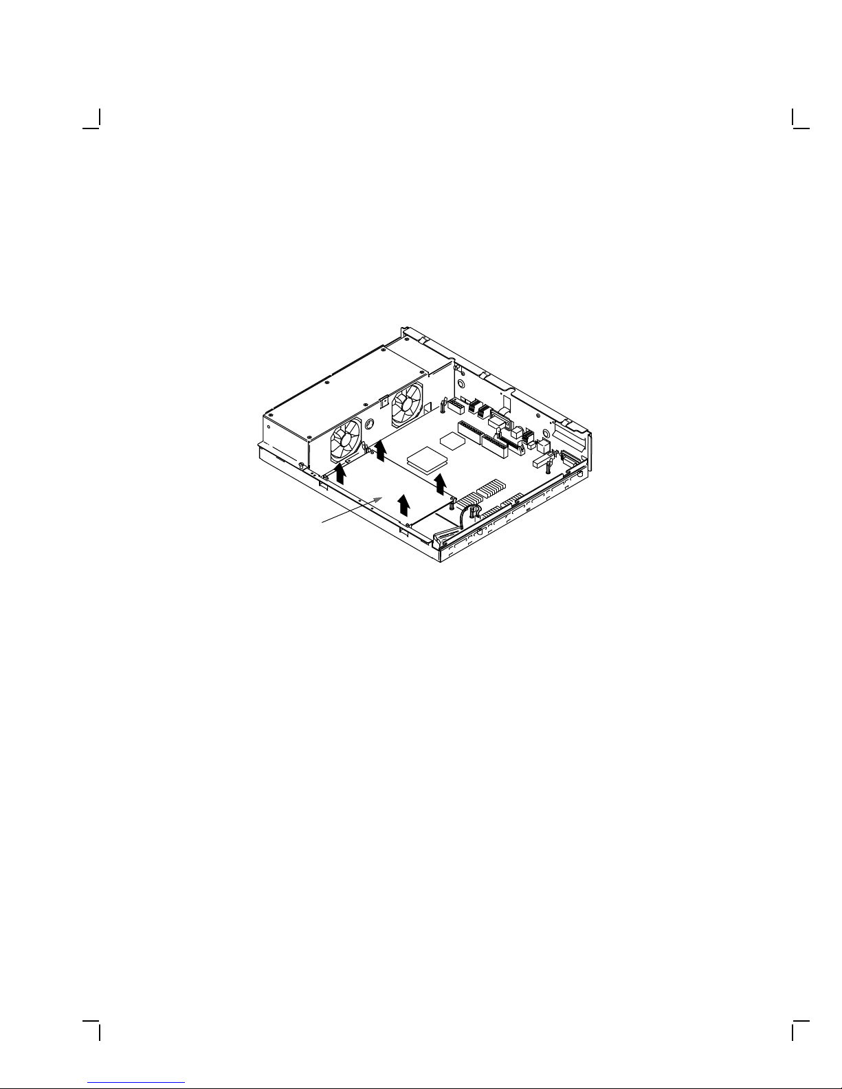
Remove the Memory Module
Remove the memory module from the four standoffs, then lift the memory
module off the system module. Two connectors will disconnect as you lift
the module.
MEMORY
MODULE
MA-X0804-88

Upgrading a Diskless Model 30 5
Remove the Graphic Module (if present)
Remove the graphic module from the four standoffs, then lift the graphic
module off the system module. Two connectors will disconnect as you lift
the module.
GRAPHICS
MODULE
MA-X0803-88
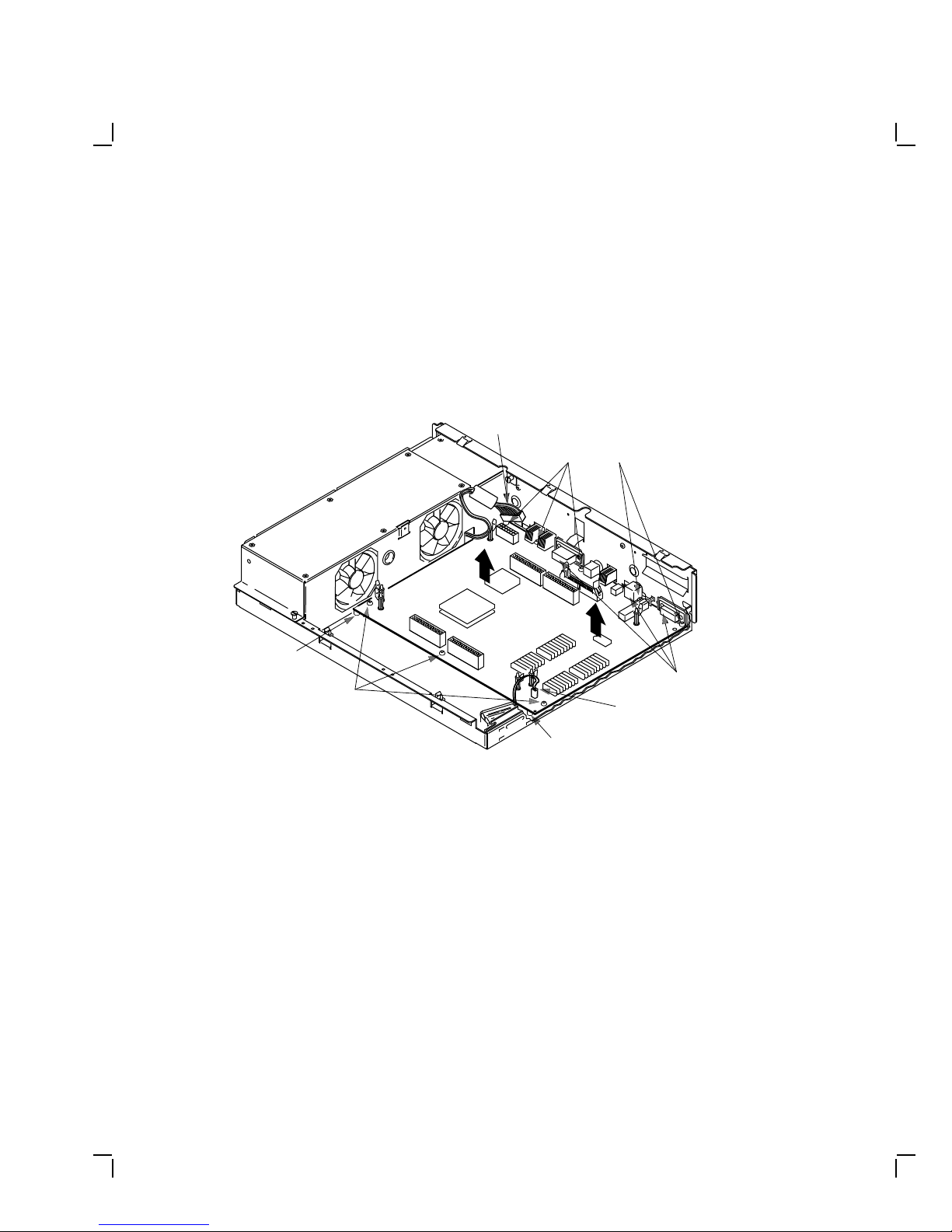
Remove the System Module
1. Disconnect all cables from the back of the system box.
6 Upgrading a Diskless Model 30
NOTE
Before disconnecting the power cable in the next step, be sure
to release the connector latch on the back side of the power
connector.
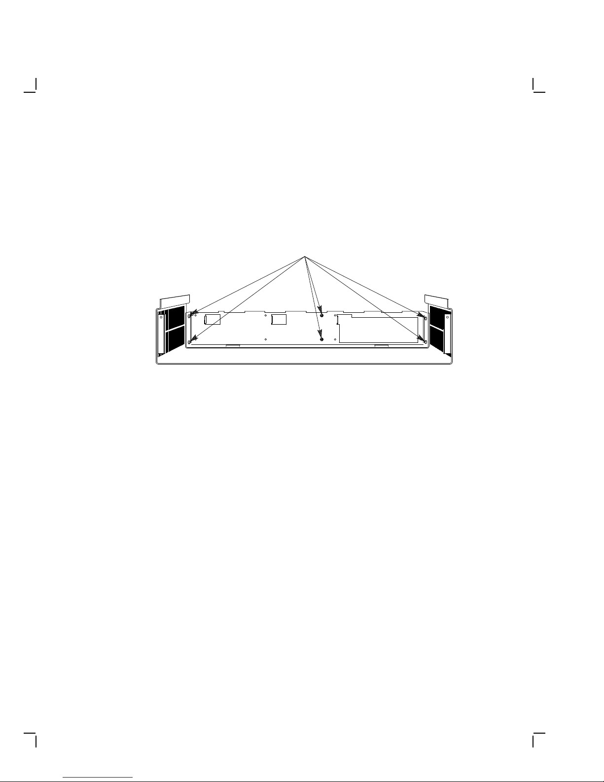
2. Disconnect the power cable and the battery cable from the system
module.
POWER
LOCATING
STANDOFF
PANHEAD
SCREWS
(3)
CABLE
PANHEAD
SCREWS
(5)
LOCATING
STANDOFF
BATTERY
CABLE
GROUND
TABS
3. Remove the eight screws from the system module.
4. Remove the system module by carefully popping off the two front
corners of the two locating standoffs.
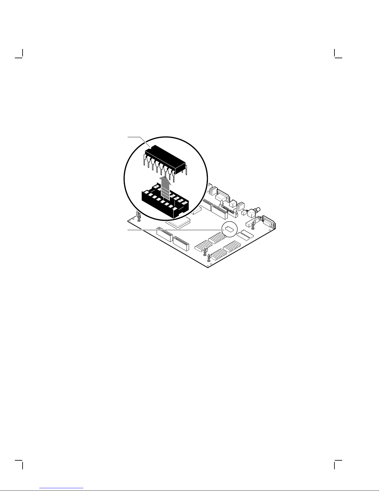
CAUTION
In the next step, you will swap the Ethernet ID ROMs on both
the new system module and the old system module that you
just removed. Be careful not to bend the pins on the ROM or
not to mix up the ROM that goes on each system module.
MA-X0805-88
Upgrading a Diskless Model 30 7
5. Remove the Ethernet ID ROM from the system module you just
removed. Set the ROM aside.
Ethernet
ID ROM
Key
Ethernet
ID ROM
MLO-002918
MA-X0872-89
6. Remove the Ethernet ID ROM from the new system module in the kit
and reinstall it on the old system module.
7. Take the ID ROM that you just removed from the old system module
and install it on the new system module.
1.3 Installing the Modules
To install the modules:
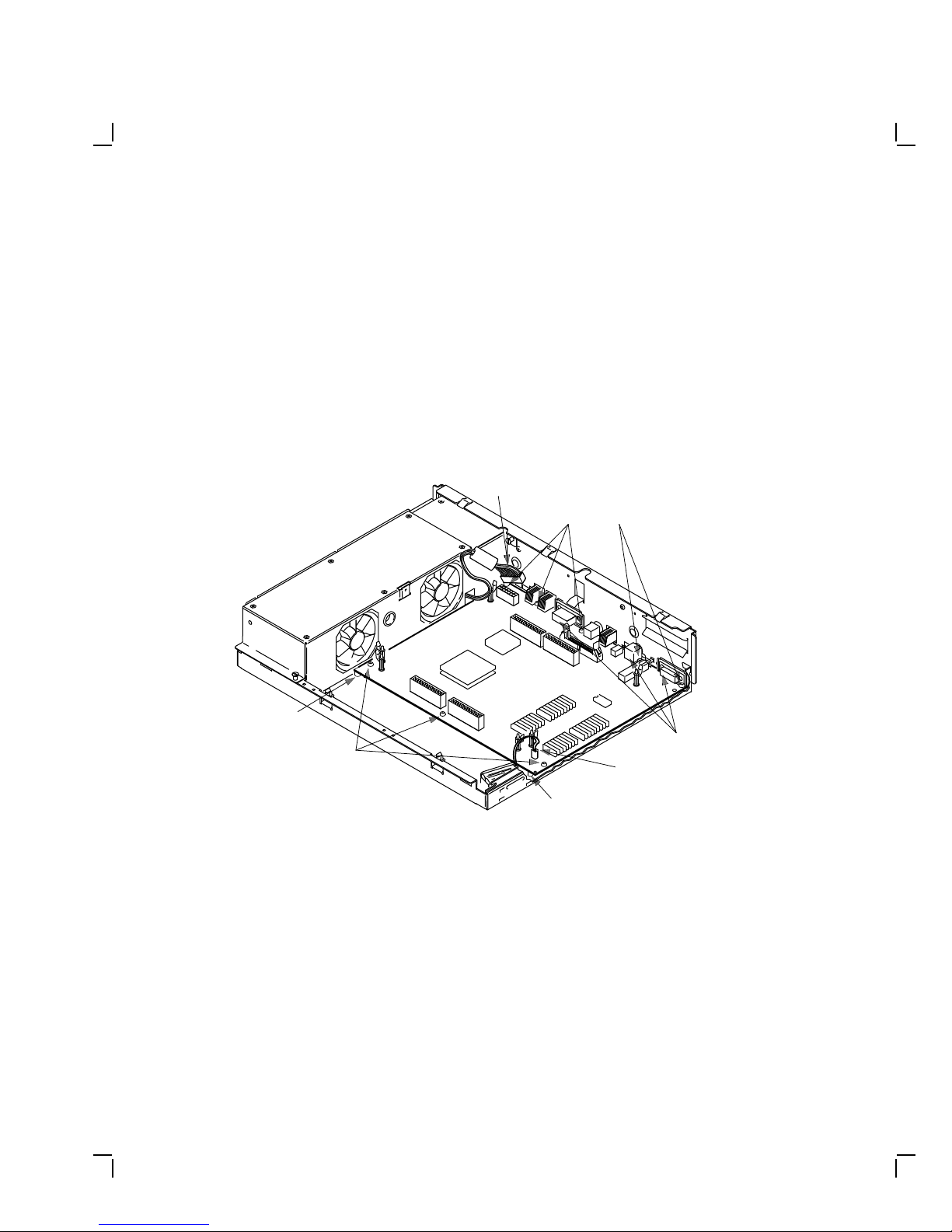
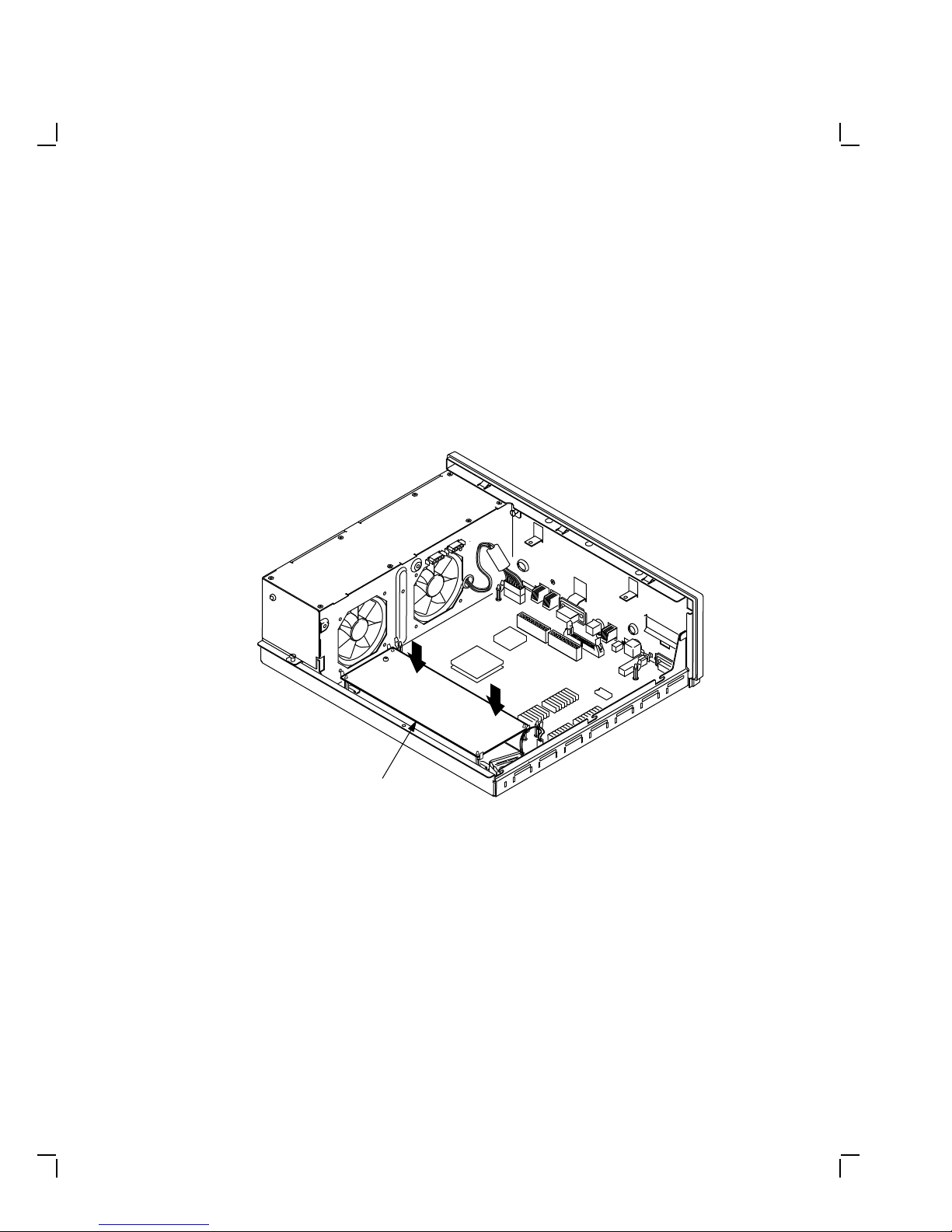
Install the New System Module
NOTE
When installing the new system module, install the connector end
first through the openings in the rear of the box. Push the module
back to load the connector ground tabs. Snap the module on both
locating standoffs. All screw holes will then be aligned.
8 Upgrading a Diskless Model 30
1. Check the position of the S3 switch next to the LEDs on the back of
the system module. Be sure S3 is in the down position. The down
position enables the monitor to be the console, and the up position
enables a terminal connected to the printer port to be the console.
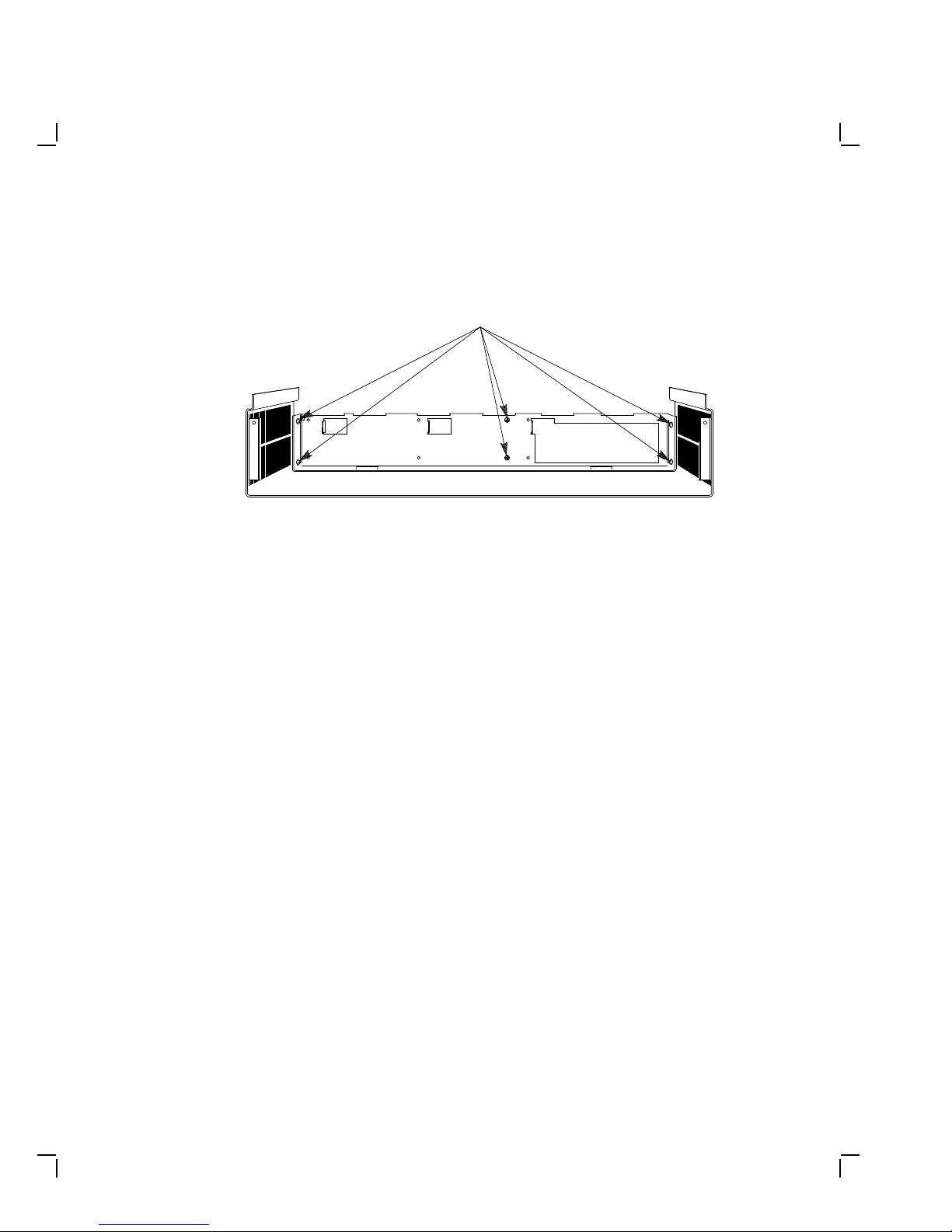
2. Install the connector end of the system module through the openings
in the rear of the box. Push the module back to load the connector
ground tabs, then snap the module on both locating standoffs. All
screw holes will then be aligned.
3. Install the eight screws on the system module.
POWER
CABLE
PANHEAD
SCREWS
(5)
LOCATING
STANDOFF
PANHEAD
SCREWS
(3)
LOCATING
STANDOFF
BATTERY
CABLE
GROUND
TABS
MA-X0805-88A
4. Connect the power cable and the battery cable to the system module.
5. Reconnect all cables to the back of the system box.
Upgrading a Diskless Model 30 9
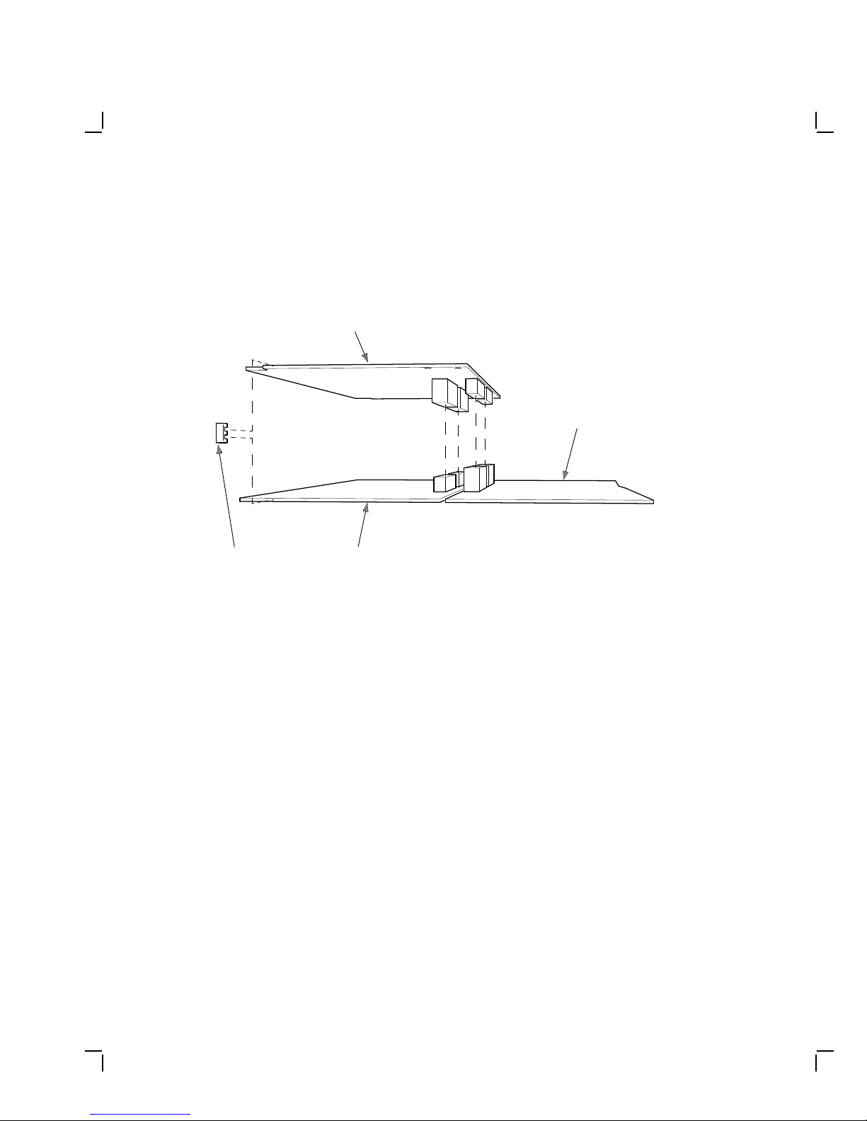
Reinstall the Memory Module
Install the memory module(s) on the new system module as shown in the
following two figures. The first figure is for 4 or 12 Mbyte (single) memory
module; the second figure is for 8 or 16 Mbyte (dual) memory module.
After the module(s) are installed, press down on top of the module’s
connectors to firmly seat the connectors.
4 or 12 Mbyte (single) Memory Module Installation
MEMORY
MODULE
MA-X0848-88A
10 Upgrading a Diskless Model 30
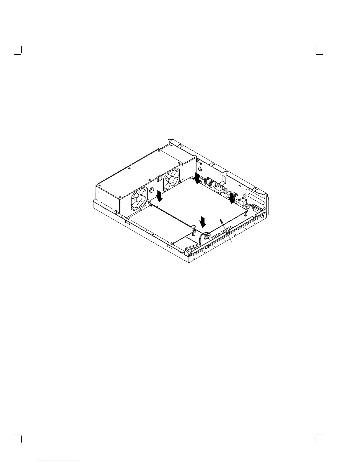
8 or 16 Mbyte (dual) Memory Module Installation
8 OR 16 MBYTE
MEMORY
MODULE
SYSTEM
MODULE
"E" CLIPS
(2 PLACES)
4 OR 12 MBYTE
MEMORY
MODULE
MA-X1174-88A
Upgrading a Diskless Model 30 11
Reinstall the Graphic Module (if present)
Reinstall the graphics module on the new system module. After the
module is installed, press down on top of the module’s connectors to firmly
seat the connectors.
GRAPHICS
MODULE
MA-X0803-88A
12 Upgrading a Diskless Model 30
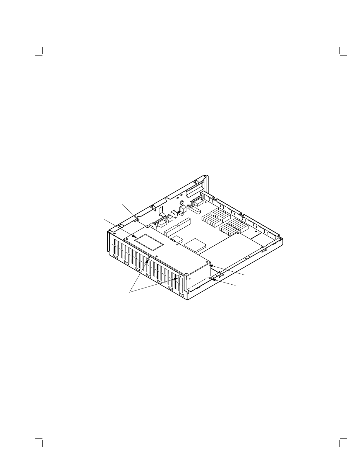
1.4 Replacing the Power Supply Screws
To replace the power supply screws:
1. Remove the two phillips-head screws from the side of the power
supply.
2. Install two of the three torx-head power supply safety screws (PN
12-30934-01) from the kit into the side of the power supply using the
torx-head screwdriver.
CAPTIVE SCREW
WARNING LABEL
WARNING
FDGSVXCWERADSFX
GHTYRUFJGHIV,DHS
HGUTKDHCBVNFHGD
POWER SUPPLY
CAPTIVE SCREW
TORX-HEAD SCREWS
3. Install the power supply warning label on the power supply.
MA-X0808-88A
Upgrading a Diskless Model 30 13
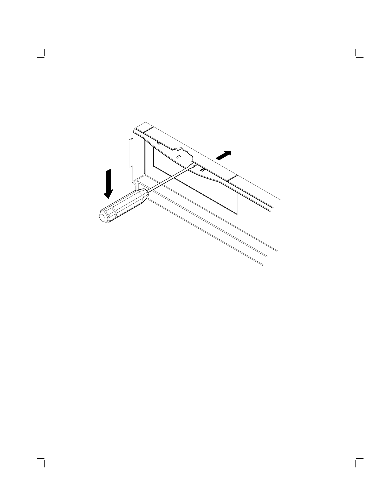
1.5 Installing the New Bezel Insert
To install the new bezel insert:
1. Remove the six screws on the cover of the system box, and remove the
front bezel from the cover.
PHILLIPS SCREWS
MA-X0517-89
14 Upgrading a Diskless Model 30
2. Separate the bezel insert from the front bezel.
MA-X0518-89
3. Install the new bezel insert from the kit on the front bezel by
reversing steps 1 and 2.
4. Remove the VAXstation 3100 medallion from the system box cover.
5. Install the new VAXstation 3100 M 38 medallion from the kit in the
cover.
Upgrading a Diskless Model 30 15
6. Reinstall the front bezel on the cover, then reinstall the six screws.
PHILLIPS SCREWS
MA-X0517-89
1.6 Installing the Upgrade Label
Install the upgrade label from the kit beside the original label on the back
of the system box.
1.7 Reinstalling the System Box Cover
To reinstall the system box cover:
1. Install the system box cover and tighten the two cover screws.
2. Refer to Chapter 1 of the maintenance guide. Run a self-test and the
system exerciser to verify the status of the new system module.
1.8 Completing the Installation
The VAXstation 3100 replaced components as well as the excess materials
(if any) from the upgrade kit are the property of Digital. You and the
customer will need to fill out the upgrade forms in Appendix A and return
them to the appropriate locations, as described in Appendix A.

2
UpgradingaModel30(NoDiskette)
This chapter contains installation procedures for upgrading a
VAXstation 3100 model 30 system without a diskette drive to a
VAXstation 3100 model 38 system without a diskette drive.
2.1 PV11U-CA Kit Contents
The following table lists the contents and part numbers of the PV11U-CA
kit:
Kit Item Part Number
KA42-BA system module 54-19356-01
Owners manual, network guide, site planning EK-VSM30-DK
VAXstation 3100 Upgrade Installation Guide EK-345AA-IN
Upgrade label 36-15946-01
Power supply caution label 36-20124-01
Medallion, VAXstation 3100 M 38
Three power supply safety screws (one screw is extra) 12-30934-01
Drive plate, MSC module, 4 cables 70-26723-01
Thirteen screw/grommets (6-32) (RZ22/RZ23 mounting
screws/grommets, four per drive)
12-31734-01
Only Used if a TZ30 Tape Drive is Installed:
Five screw/grommets(metric M3) 12-31734-02
Bezel insert for the TZ30 tape drive 74-37501-01
TZ30 plate 74-39199-01
TZ30 mounting screws/grommets, one screw is extra.
16

Upgrading a Model 30 (No Diskette) 17
Kit Item Part Number
Two TZ30 plate mounting screws 90-09984-07
2.2 Preparing the System for Installation
To prepare the system for installation:
Shut Down the System
1. Shut down the system software.
2. Run a self-test to verify the operation of the present configuration.
>>> TEST F 1
3. Turn the system power switch off.
Open the System Box
CAUTION
Wear a static wrist strap and use a static mat (PN 29-26242-00)
when replacing FRUs.
18 Upgrading a Model 30 (No Diskette)
1. Unscrew the two cover screws.
COVER
SCREW
LOCATIONS
2. Slide the cover forward and up off the system box.
MA-X0796-88
Upgrading a Model 30 (No Diskette) 19
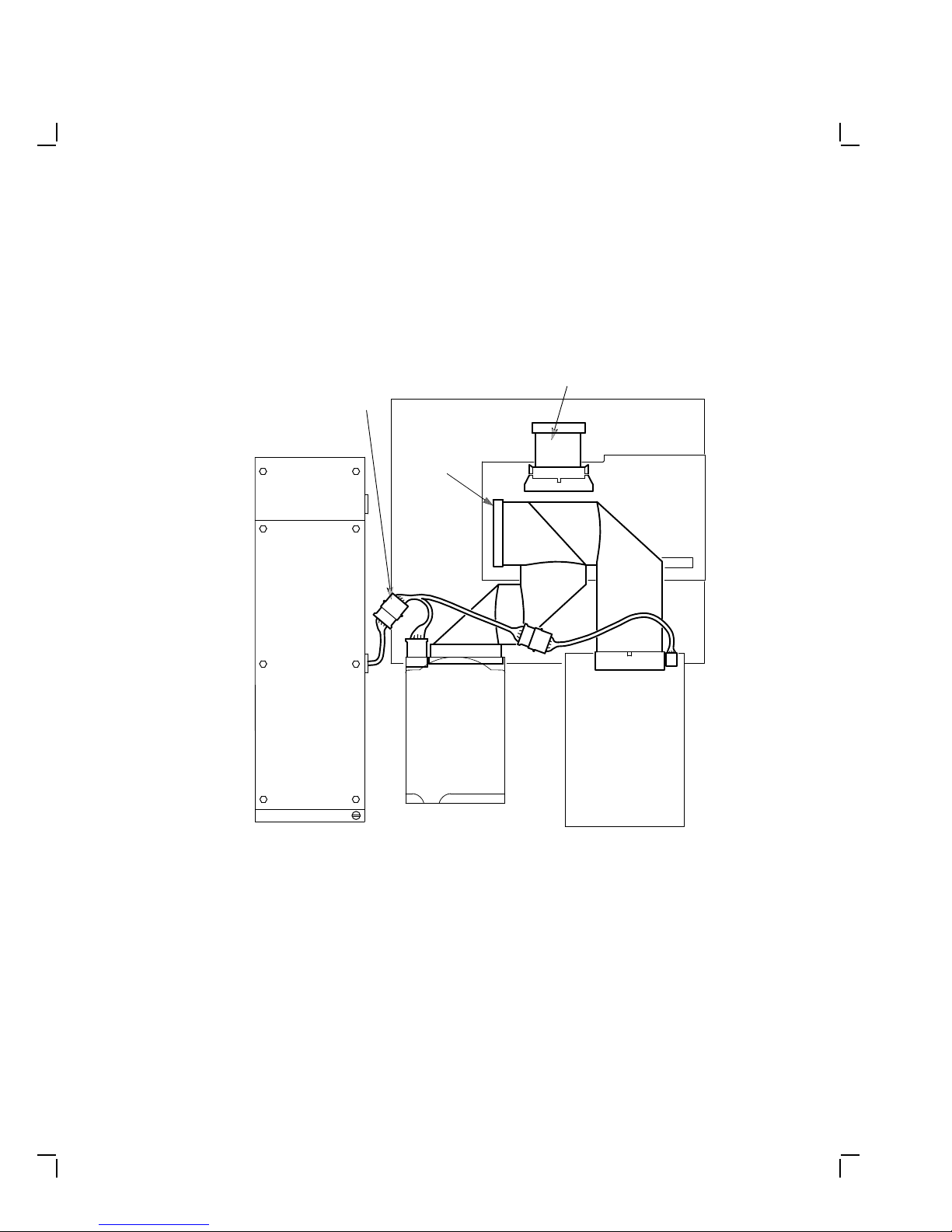
Remove the Drive Mounting Plate
1. Disconnect the power cable from the power supply and disconnect the
cable on the mass storage controller (MSC) module that goes to the
system module.
POWER
SUPPLY
POWER
CABLE
SYSTEM MODULE
A-BUS
RZ23
MSC CABLE
TZ30
MSC
MODULE
2. Disconnect the external SCSI cable or the terminator from the SCSI
port.
MA-X1172-88
20 Upgrading a Model 30 (No Diskette)
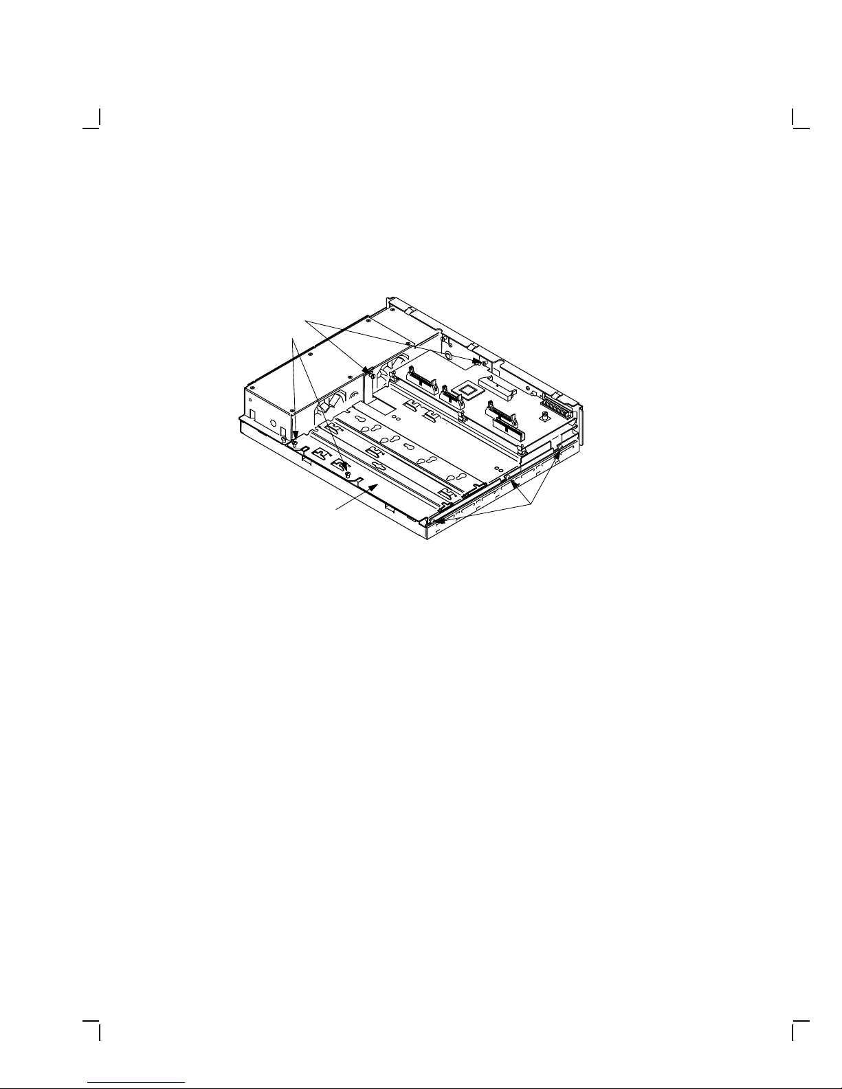
3. Unscrew the four captive screws, loosen the three panhead screws,
and remove the drive mounting plate.
CAPTIVE
SCREWS
(4)
DRIVE PLATE
PANHEAD
SCREWS
(3 LOOSENED)
MA-X0527-89A
Remove the Drives from the Drive Plate
1. Disconnect all cables from all drives on the old drive mounting plate
and set them aside. They will not be reused.
2. Remove all drives from the old drive mounting plate. The mounting
screws and their grommets will not be reused.
Upgrading a Model 30 (No Diskette) 21
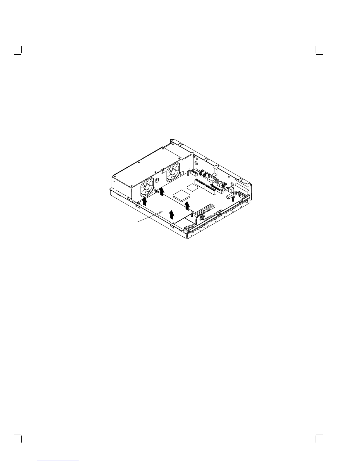
Remove the Memory Module
Remove the memory module from the four standoffs, then lift the memory
module off the system module. Two connectors will disconnect as you lift
the module.
MEMORY
MODULE
MA-X0804-88
22 Upgrading a Model 30 (No Diskette)
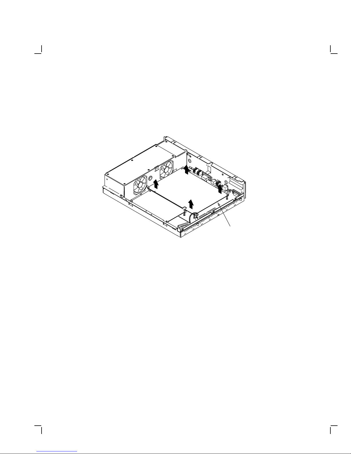
Remove the Graphic Module (if present)
Remove the graphic module from the four standoffs, then lift the graphic
module off the system module. Two connectors will disconnect as you lift
the module.
GRAPHICS
MODULE
MA-X0803-88
 Loading...