

Digital Equipment VAX 6000 XMI-1, VAX 6000 XMI Series, VAX 6000 XMI-2 Conversion Manual

VAX 6000 XMI Conversion Manual
Order Number EK–650EB–UP–002
This manual details the procedure for the full power
and packaging upgrade from a VAX 6000 Model 200,
300, or 400 system with an XMI-1 card cage to a
system with an XMI-2 card cage.
digital equipment corporation
maynard, massachusetts

First Printing, December 1990
Revised, July 1991
The information in this document is subject to change without notice and should not be
construed as a commitment by Digital Equipment Corporation.
Digital Equipment Corporation assumes no responsibility for any errors that may appear in
this document.
The software, if any, described in this document is furnished under a license and may be used
or copied only in accordance with the terms of such license. No responsibility is assumed
for the use or reliability of software or equipment that is not supplied by Digital Equipment
Corporation or its affiliated companies.
Copyright ©1991 by Digital Equipment Corporation.
All Rights Reserved.
Printed in U.S.A.
The following are trademarks of Digital Equipment Corporation:
DEC PDP VAXcluster
DEC LANcontroller ULTRIX VAXELN
DECnet UNIBUS VMS
DECUS VAX XMI
DWMVA VAXBI
FCC NOTICE: The equipment described in this manual generates, uses, and may emit
radio frequency energy. The equipment has been type tested and found to comply with the
limits for a Class A computing device pursuant to Subpart J of Part 15 of FCC Rules, which
are designed to provide reasonable protection against such radio frequency interference when
operated in a commercial environment. Operation of this equipment in a residential area
may cause interference, in which case the user at his own expense may be required to take
measures to correct the interference.

Contents
Preface vii
Chapter 1 Specifications and Preparation
1.1 Upgrade Kit Overview . . . . . . . . . . . . . . . . . . . . . . . . . . . . . . 1–2
1.2 Battery Backup Kit Specifications . . . . . . . . . . . . . . . . . . . . . 1–4
1.3 Save EEPROM Contents to TK Tape . . . . . . . . . . . . . . . . . . . 1–6
1.4 Record System Parameters . . . . . . . . . . . . . . . . . . . . . . . . . . 1–8
1.5 Prepare Area, Kits, and Tools . . . . . . . . . . . . . . . . . . . . . . . . 1–10
1.6 Unpacking Checklist . . . . . . . . . . . . . . . . . . . . . . . . . . . . . . . 1–12
Chapter 2 XMI-1 to XMI-2 Conversion
2.1 Full Upgrade Procedure Overview . . . . . . . . . . . . . . . . . . . . . 2–2
2.2 Step 1, Remove the XMI-1 Card Cage . . . . . . . . . . . . . . . . . . 2–4
2.2.1 Prepare for Removal . . . . . . . . . . . . . . . . . . . . . . . . . . . . . 2–4
2.2.2 Remove the XMI-1 Card Cage from the Cabinet . . . . . . . . 2–8
2.3 Step 2, Remove the H7214 Power Regulator(s) . . . . . . . . . . . 2–10
2.3.1 Replace the H7214 in Position 2, if Necessary . . . . . . . . . . 2–12
2.3.2 Remove the H7214 in Position 3 . . . . . . . . . . . . . . . . . . . . 2–14
2.4 Step 3, Install the H7242 Power Regulator . . . . . . . . . . . . . . 2–16
2.5 Step 4, Install the XMI-2 Card Cage . . . . . . . . . . . . . . . . . . . 2–18
2.5.1 Attach the Daughter Card and Install the Card Cage . . . . 2–19
2.5.2 Attach XMI-2 Card Cage Cables . . . . . . . . . . . . . . . . . . . . 2–20
2.5.3 Complete XMI-2 Cabling . . . . . . . . . . . . . . . . . . . . . . . . . . 2–24
2.6 Step 5, Replace the XTC Power Sequencer . . . . . . . . . . . . . . 2–26
2.7 Step 6, Remove the H7231-N Battery Backup Unit . . . . . . . . 2–28
2.8 Step 7, Replace the Power and Logic Unit . . . . . . . . . . . . . . . 2–30
2.8.1 Remove the H7206-A Power and Logic Unit . . . . . . . . . . . 2–31
2.8.2 Replace the Power and Logic Unit Mounting Plate . . . . . . 2–32
iii

2.8.3 Install the H7206-B Power and Logic Unit . . . . . . . . . . . . 2–34
2.8.4 Apply Power to Check Conversion . . . . . . . . . . . . . . . . . . . 2–36
Chapter 3 Wrap-Up and Troubleshooting
3.1 Insert XMI Modules . . . . . . . . . . . . . . . . . . . . . . . . . . . . . . . . 3–2
3.2 Install DWMBB Adapters . . . . . . . . . . . . . . . . . . . . . . . . . . . 3–4
3.3 Reattach Doors, Change System Number, and Attach Product
Conversion Label . . . . . . . . . . . . . . . . . . . . . . . . . . . . . . . . . . 3–6
3.4 Restore Power to System . . . . . . . . . . . . . . . . . . . . . . . . . . . . 3–8
3.5 H7206-B Diagnostic LEDs . . . . . . . . . . . . . . . . . . . . . . . . . . . 3–10
3.6 H7206-B LEDs During Normal Power-Up . . . . . . . . . . . . . . . 3–12
3.7 Sample Self-Test Failures . . . . . . . . . . . . . . . . . . . . . . . . . . . 3–14
3.8 Pack Up and Return Replaced Items . . . . . . . . . . . . . . . . . . . 3–16
Appendix A Module Handling
A.1 Handling Modules . . . . . . . . . . . . . . . . . . . . . . . . . . . . . . . . . A–2
A.2 Inserting Modules . . . . . . . . . . . . . . . . . . . . . . . . . . . . . . . . . A–4
Appendix B Power-Up Troubleshooting Procedures
B.1 Power-Up with Inhibit Cable and XMI-1 Modules Installed . . B–2
B.2 Normal Operation with Model 500 CPUs and No Inhibit
Cable . . . . . . . . . . . . . . . . . . . . . . . . . . . . . . . . . . . . . . . . . . . B–3
Index
Examples
1–1 SAVE EEPROM Command . . . . . . . . . . . . . . . . . . . . . . . . . . 1–6
1–2 Show All System Parameters . . . . . . . . . . . . . . . . . . . . . . . . . 1–8
3–1 Sample Self-Test Failures . . . . . . . . . . . . . . . . . . . . . . . . . . . 3–14
iv

Figures
1–1 Overview of Full Upgrade . . . . . . . . . . . . . . . . . . . . . . . . . . . 1–2
1–2 Battery Backup Installation . . . . . . . . . . . . . . . . . . . . . . . . . . 1–4
1–3 System Space Requirements . . . . . . . . . . . . . . . . . . . . . . . . . 1–10
2–1 Upgrade Overview . . . . . . . . . . . . . . . . . . . . . . . . . . . . . . . . . 2–2
2–2 XMI-1 Backplane Cables and Power Connections . . . . . . . . . 2–4
2–3 XMI-1 Backplane Diagram . . . . . . . . . . . . . . . . . . . . . . . . . . . 2–6
2–4 Power Control/Status Cable . . . . . . . . . . . . . . . . . . . . . . . . . . 2–6
2–5 XMI-1 Card Cage . . . . . . . . . . . . . . . . . . . . . . . . . . . . . . . . . . 2–8
2–6 Remove the H7214 Power Regulator(s) . . . . . . . . . . . . . . . . . 2–10
2–7 Replace the H7214 in Position 2 . . . . . . . . . . . . . . . . . . . . . . 2–12
2–8 Bulk Power Cable to Power Regulators . . . . . . . . . . . . . . . . . 2–13
2–9 Remove the H7214 in Position 3 . . . . . . . . . . . . . . . . . . . . . . 2–14
2–10 H7242 Power Regulator Installation . . . . . . . . . . . . . . . . . . . 2–16
2–11 XMI Backplane and Daughter Card . . . . . . . . . . . . . . . . . . . . 2–18
2–12 XMI-2 Card Cage . . . . . . . . . . . . . . . . . . . . . . . . . . . . . . . . . . 2–20
2–13 XMI-2 Bus Bars . . . . . . . . . . . . . . . . . . . . . . . . . . . . . . . . . . . 2–21
2–14 Power Control/Status Cable . . . . . . . . . . . . . . . . . . . . . . . . . . 2–22
2–15 Complete XMI-2 Cabling . . . . . . . . . . . . . . . . . . . . . . . . . . . . 2–24
2–16 Replace the XTC Power Sequencer Module . . . . . . . . . . . . . . 2–26
2–17 H7231-N Battery Backup Unit Removal . . . . . . . . . . . . . . . . 2–28
2–18 H7206-A Power and Logic Unit Removal (Top View) . . . . . . . 2–30
2–19 Attaching BeCu Clips to New Mounting Plate . . . . . . . . . . . . 2–32
2–20 H7206-B Power and Logic Unit (Top View) . . . . . . . . . . . . . . 2–34
2–21 H7242 Inhibit Cable . . . . . . . . . . . . . . . . . . . . . . . . . . . . . . . . 2–36
3–1 Module Utilization Label . . . . . . . . . . . . . . . . . . . . . . . . . . . . 3–2
3–2 VAX 6000 Series Slot Numbers . . . . . . . . . . . . . . . . . . . . . . . 3–4
3–3 Front Door (Inside View) . . . . . . . . . . . . . . . . . . . . . . . . . . . . 3–6
3–4 Product Conversion Label . . . . . . . . . . . . . . . . . . . . . . . . . . . 3–7
3–5 AC Power Controller Circuit Breaker . . . . . . . . . . . . . . . . . . 3–8
3–6 Power-Up Troubleshooting Flowchart . . . . . . . . . . . . . . . . . . 3–9
3–7 H7206-B Diagnostic LEDs . . . . . . . . . . . . . . . . . . . . . . . . . . . 3–10
3–8 H7206-B LEDs During Normal Power-Up . . . . . . . . . . . . . . . 3–12
A–1 Holding 6000 Series Processor Modules . . . . . . . . . . . . . . . . . A–2
A–2 Inserting the Scalar Processor in an XMI Card Cage . . . . . . . A–4
A–3 Inserting the Vector Processor in an XMI Card Cage . . . . . . . A–4
v

Tables
1 VAX 6000 Series Documentation . . . . . . . . . . . . . . . . . . . . . . viii
2 VAX 6000 Model Level Documentation . . . . . . . . . . . . . . . . . ix
3 Associated Documents . . . . . . . . . . . . . . . . . . . . . . . . . . . . . . x
1–1 Components to Be Replaced . . . . . . . . . . . . . . . . . . . . . . . . . . 1–3
1–2 Battery Backup Kit H7236-A . . . . . . . . . . . . . . . . . . . . . . . . . 1–5
1–3 Tools and Supplies Required . . . . . . . . . . . . . . . . . . . . . . . . . 1–11
1–4 H9657-CU Platform Upgrade Components. . . . . . . . . . . . . . . 1–12
B–1 H7206-B Diagnostic LEDs . . . . . . . . . . . . . . . . . . . . . . . . . . . B–1
vi

Preface
Intended Audience
This manual is written for the Digital customer service engineer who is
upgrading a VAX 6000 Model 200, 300, or 400 system with a +5V XMI-1
card cage to a +3.3V XMI-2 card cage.
Document Structure
This manual uses a structured documentation design. There are many
topics, organized into small sections for efficient reference. Each topic
begins with an abstract. You can gain an overview by reading only the
abstracts. Next is an illustration or example, which also provides quick
reference. Last in the structure is descriptive text.
This manual has three chapters and two appendixes, as follows:
• Chapter 1, Specifications and Preparation, gives an overview of
the power upgrade and conversion described in this manual.
• Chapter 2, XMI-1 to XMI-2 Conversion, gives the details of the XMI
and power upgrade.
• Chapter 3, Wrap-Up and Troubleshooting, explains how to verify
the system and what to do if something goes wrong.
• Appendix A describes the proper handling of modules.
• Appendix B describes power-up troubleshooting procedures.
vii
Conventions Used in This Document
The icons shown below are used in illustrations for designating part
placement in VAX 6000 systems. A shaded area in the icon shows the
location of the component or part being discussed.
FRONT
REAR
VAX 6000 Series Documents
There are two sets of documentation: manuals that apply to all VAX 6000
series systems and manuals that are specific to one VAX 6000 model.
Table 1 lists the manuals in the VAX 6000 series documentation set.
Table 1: VAX 6000 Series Documentation
Title Order Number
Operation
VAX 6000 Series Owner ’s Manual EK–600EA–OM
VAX 6000 Series Vector Processor Owner ’s Manual EK–60VAA–OM
VAX 6000 Vector Processor Programmer’s Guide EK–60VAA–PG
Service and Installation
VAX 6000 Platform Technical User’s Guide EK–600EA–TM
VAX 6000 Series Installation Guide EK–600EA–IN
VAX 6000 Installationsanleitung EK–600GA–IN
VAX 6000 Guide d’installation EK–600FA–IN
VAX 6000 Guia de instalacion EK–600SA–IN
viii

Table 1 (Cont.): VAX 6000 Series Documentation
Title Order Number
Service and Installation
VAX 6000 Platform Service Manual EK–600EA–MG
Options and Upgrades
VAX 6000: XMI Conversion Manual EK–650EB–UP
VAX 6000: Installing MS65A Memories EK–MS65A–UP
VAX 6000: Installing the H7236-A Battery Backup Option EK–60BBA–IN
VAX 6000: Installing the FV64A Vector Option EK–60VEA–IN
VAX 6000: Installing the VAXBI Option EK–60BIA–IN
Manuals specific to models are listed in Table 2.
Table 2: VAX 6000 Model Level Documentation
Title Order Number
Models 200/300/400
VAX 6000 Model 300 and 400 Service Manual EK–624EA–MG
VAX 6000: Installing Model 200/300/400 Processors EK–6234A–UP
Model 500
VAX 6000 Model 500 Mini-Reference EK–650EA–HR
VAX 6000 Model 500 Service Manual EK–650EA–MG
VAX 6000 Model 500 System Technical User’s Guide EK–650EA–TM
VAX 6000: Installing Model 500 Processors EK–KA65A–UP
Associated Documents
Table 3 lists other documents that you may find useful.
ix

Table 3: Associated Documents
Title Order Number
System Hardware Options
VAXBI Expander Cabinet Installation Guide EK–VBIEA–IN
VAXBI Options Handbook EB–32255–46
System I/O Options
CIBCA User Guide EK–CIBCA–UG
CIXCD Interface User Guide EK–CIXCD–UG
DEC LANcontroller 200 Installation Guide EK–DEBNI–IN
DEC LANcontroller 400 Installation Guide EK–DEMNA–IN
InfoServer 100 Installation and Owners Guide EK–DIS1K–IN
KDB50 Disk Controller User’s Guide EK–KDB50–UG
KDM70 Controller User Guide EK–KDM70–UG
RRD40 Disc Drive Owner’s Manual EK–RRD40–OM
RA90/RA92 Disk Drive User Guide EK–ORA90–UG
SA70 Enclosure User Guide EK–SA70E–UG
Operating System Manuals
Guide to Maintaining a VMS System AA–LA34A–TE
Guide to Setting Up a VMS System AA–LA25A–TE
Introduction to VMS System Management AA–LA24A–TE
ULTRIX–32 Guide to System Exercisers AA–KS95B–TE
VMS Upgrade and Installation Supplement: VAX 6000 Series AA–LB36C–TE
VMS Networking Manual AA–LA48A–TE
VMS System Manager’s Manual AA–LA00A–TE
VMS VAXcluster Manual AA–LA27B–TE
x

Table 3 (Cont.): Associated Documents
Title Order Number
Peripherals
HSC Installation Manual EK–HSCMN–IN
H4000 DIGITAL Ethernet Transceiver Installation Manual EK–H4000–IN
Installing and Using the VT320 Video Terminal EK–VT320–UG
RV20 Optical Disk Owner ’s Manual EK–ORV20–OM
SC008 Star Coupler User’s Guide EK–SC008–UG
TA78 Magnetic Tape Drive User’s Guide EK–OTA78–UG
TA90 Magnetic Tape Subsystem Owner’s Manual EK–OTA90–OM
TK70 Streaming Tape Drive Owner ’s Manual EK–OTK70–OM
TU81/TA81 and TU/81 PLUS Subsystem User’s Guide EK–TUA81–UG
VAX Manuals
VAX Architecture Reference Manual EY–3459E–DP
VAX Systems Hardware Handbook — VAXBI Systems EB–31692–46
VAX Vector Processing Handbook EC–H0739–46
xi

Chapter 1
Specifications and Preparation
This chapter describes the preliminary steps to be performed in upgrading
a VAX 6000 XMI-1 platform to an XMI-2 platform. This upgrade converts
an older Model 200, 300, or 400 system to a Model 500.
If the Model 500 does not need more than four processors, more than 12 XMI
slots, or require battery backup, a simpler upgrade is possible as described
in the VAX 6000: Installing Model 500 Processors manual.
Sections in this chapter include:
• Upgrade Kit Overview
• Battery Backup Kit Specifications
• Save EEPROM Contents to TK Tape
• Record System Parameters
• Prepare Area, Kits, and Tools
• Unpacking Checklist
Specifications and Preparation 1–1
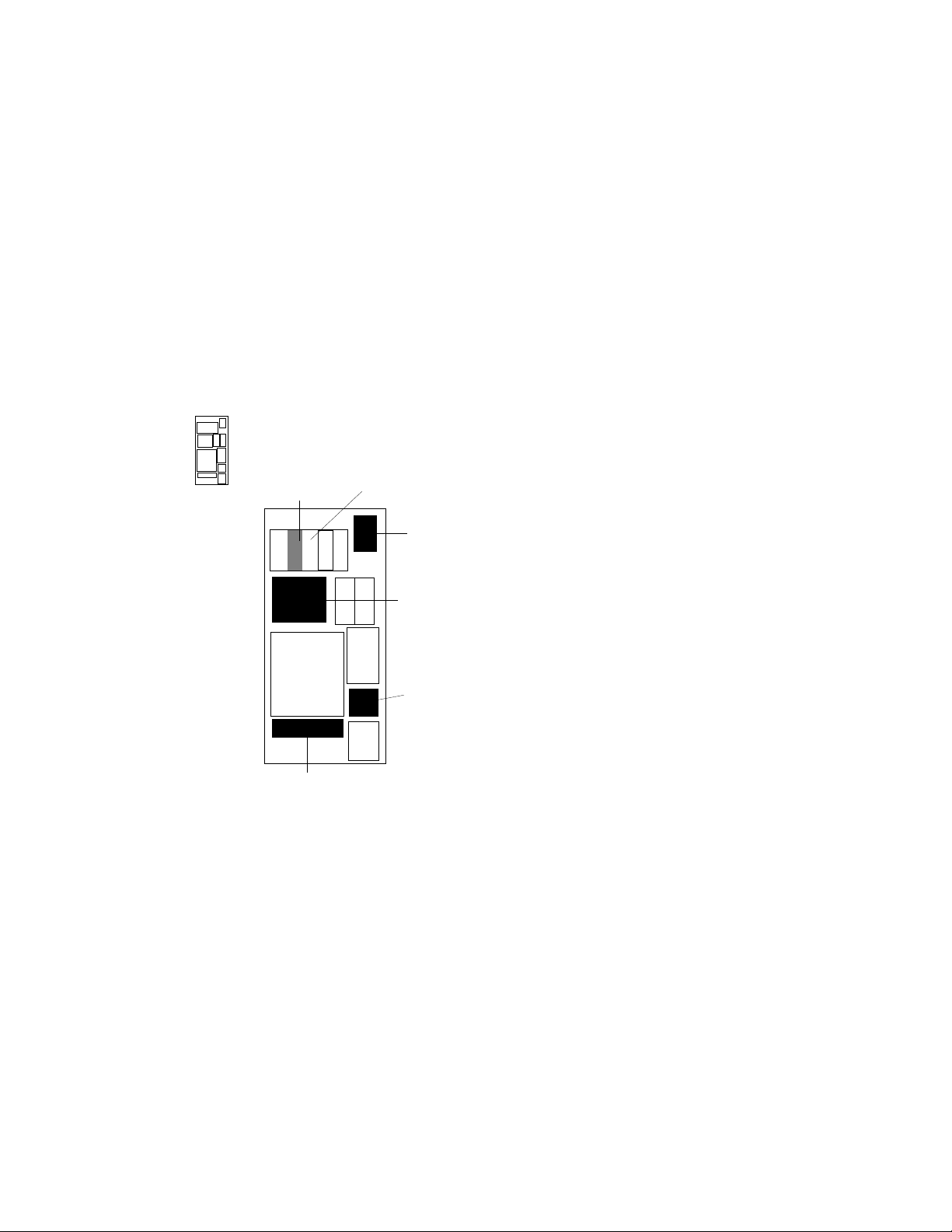
1.1 Upgrade Kit Overview
Upgrade order number H9657–CU takes a VAX 6000 Model
200, 300, or 400 system with an XMI-1 power system and
upgrades it to a VAX 6000 Model 500 with an XMI-2 power
system. The upgrade adds +3.3 volt power, an XMI-2
backplane preassembled with bus bars and cables, and an
H7206-B power and logic unit.
Figure 1–1: Overview of Full Upgrade
REAR
POSSIBLE
UPGRADE TO
H7214
REMOVE H7231
BATTERY BACKUP
UNIT
REPLACE H7214
WITH AN H7242
REPLACE XTC
POWER SEQUENCER
MODULE
REPLACE XMI
CARD CAGE
ASSEMBLY
REPLACE H7206
POWER AND LOGIC
UNIT
msb-0379-90
1–2 VAX 6000 XMI Conversion Manual

Table 1–1 lists the components you will remove. See Table 1–4 for the
listing of components in the upgrade kit. See Chapter 2 for the full upgrade
procedures.
NOTE: Before you start, make sure you have enough ESD boxes for
all processor, DWMBA, and memory modules from the system you are
upgrading.
Table 1–1: Components to Be Replaced
Part Number Description
H7206-A Power and logic unit
70-24902-01 XMI-1 card cage assembly
H7214 +5V regulator, located in position 3
H7214 The second XMI +5V regulator, if at A or B revision level
20-29176-01 XTC power sequencer module
17-01833-01 H405 fail safe enable cable
KA64A/KA62A/KA62B Processors
MS62A Memories
74-39700-XX Old system name plate mounted on the door
17-01549-01 H7206 to H405 DEC power bus cable
H7231-N Battery backup unit, if present
Specifications and Preparation 1–3
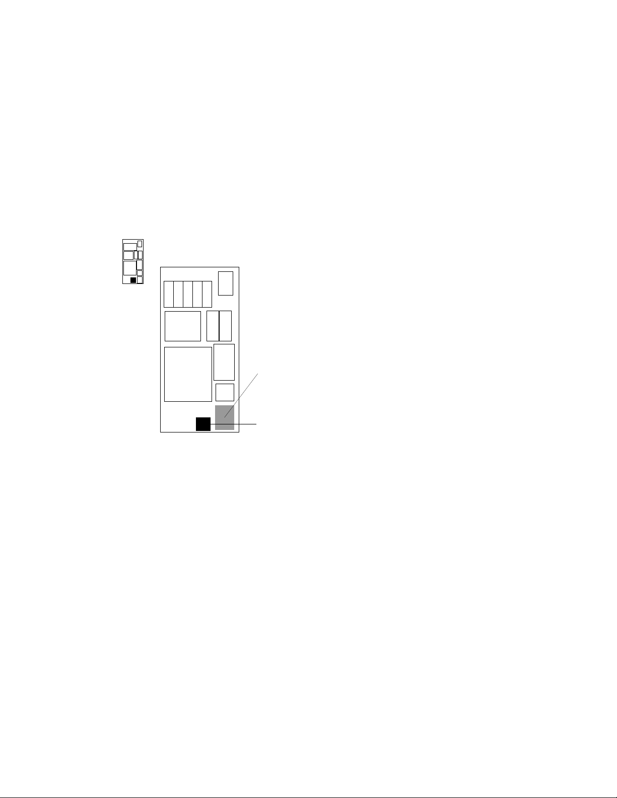
1.2 Battery Backup Kit Specifications
If the VAX 6000 system that you are upgrading has or
requires battery backup, you must install the battery
backup option kit order number H7236-A.
Figure 1–2: Battery Backup Installation
REAR
REPLACE THE H405
AC POWER CONTROLLER,
IF NECESSARY
INSTALL BATTERY
BACKUP UNIT
1–4 VAX 6000 XMI Conversion Manual
msb-0380-90

See VAX 6000: Installing the H7236-A Battery Backup Option, which
ships with the battery backup unit (BBU), for a description of the BBU
installation procedures. Table 1–2 lists the major components in the BBU
kit.
Table 1–2: Battery Backup Kit H7236-A
Part Number Description
30-31264-01 Battery backup unit
17-02975-01 Battery backup signal cable
17-02485-01 Battery backup DC power cable
17-00442-27 Battery backup AC power cable
If the H405-E AC power controller is below revision level F, it must be
replaced. If an H405-F AC power controller is below revision level H, it
must be replaced when an H7236-A battery backup unit is installed.
Specifications and Preparation 1–5

1.3 Save EEPROM Contents to TK Tape
Begin preparation for the upgrade by saving the EEPROM
contents to a TK tape. With a blank cartridge in the tape
drive, use the SAVE EEPROM command to copy the contents
of the boot processor’s EEPROM to tape.
Example 1–1: SAVE EEPROM Command
! A blank TK tape is in the tape drive. With the upper
! key switch at Enable and the lower key switch at Halt,
! press the Restart button.
#123456789 0123456789 0123456789 01234567#
F E D C B A 9 8 7 6 5 4 3 2 1 0 NODE #
A A . . M M . . . . . . P P TYP
o o . . + + . . . . . . + + STF
. . . . . . . . . . . . E B BPD
. . . . . . . . . . . . + + ETF
. . . . . . . . . . . . E B BPD
. . . . . . . . . + . + . . + . XBI D +
. . . . . . . . . + . + . . + . XBI E +
. . . . A2 A1 . . . . . . . . ILV
. . . . 32 32 . . . . . . . . 64 Mb
ROM0 = V1.00 ROM1 = V1.00 EEPROM = 1.00/1.00
>>> SAVE EEPROM
Proceed with save to tape? (Y or N) >>> Y
?6B EEPROM saved to tape successfully.
7
>>>
4
! Enter SAVE command.
! System prompts user to proceed.
! Enter a Y to continue.
! System confirms SAVE is complete.
2
3
SN = SG01234567
5
6
1
Before doing an upgrade you should save the contents of the boot processor’s
EEPROM by copying the image to a TK cartridge. Earlier VAX 6000
systems have TK50 tape drives; later models have TK70 tape drives. The
operation of the TK50 differs slightly from the TK70. See Appendix A of
the Owner’s Manual for your system for more information on the TK tape
drive.
1–6 VAX 6000 XMI Conversion Manual

Example 1–1 shows the steps to save the EEPROM contents:
1
Put a blank TK cartridge in the tape drive. Put the control panel’s
upper key switch in the Enable position and the lower key switch in
the Halt position, and then press the Restart button to generate self-test
results. See the Owner’s Manual for your system for a full explanation
of self-test results.
2
These numbers appear for Model 400 systems and indicate the progress
of self-test. The progress trace line is displayed by the processor in slot
1.
3
Note the values here for the EEPROM. The second number indicates if
any patches have been installed. Whenever you do an upgrade, make
sure that the boot processor has the latest patches installed on its
EEPROM before you perform the save operation.
4
Following self-test, the console prompt appears. At the prompt, enter
SAVE EEPROM. This operation saves the information from the boot
processor and overwrites any existing information on the TK cartridge.
5
The console program queries you, requiring your confirmation to
proceed with the SAVE EEPROM operation. Enter Y. The save process
takes less than a minute to complete.
6
The console program confirms that the save operation has completed
successfully. When the console prompt returns, the save operation is
complete. Saved information includes:
System serial number
Systemwide console parameters (baud rate, interleave, terminal
characteristics)
Saved boot specifications
Diagnostic patches
Console patches
Boot primitives
7
Rewind the tape and remove the cartridge from the drive. Label and
write-protect the tape.
NOTE: This tape should be used only on this system. Each system
has its own identifying information stored in the processor EEPROMs.
Furthermore, tapes written by a TK50 tape drive are formatted differently
from those written by a TK70 tape drive. The TK70 can read data from a
tape written by a TK50, but it cannot overwrite a tape originally written by
a TK50. A TK50, however, cannot read data from a tape written by a TK70.
Specifications and Preparation 1–7

1.4 Record System Parameters
Save a printout of the system parameters, which you’ll want
to restore after the power conversion and installation of the
KA65A modules.
Example 1–2: Show All System Parameters
>>> SHOW ALL
Type Rev ! Lists all system parameters,
1+ KA64A (8082) 0006 ! beginning with the system
2+ KA64A (8082) 0006 ! configuration
9+ MS62A (4001) 0002
A+ MS62A (4001) 0002
D+ DWMBA/A (2001) 0002
E+ DWMBA/A (2001) 0002
XBI D
1+ DWMBA/B (2017) 0007
4+ KDB50 (010E) 0F1C
6+ DEBNI (0118) 0100
XBI E
1+ DWMBA/A (2017) 0007
4+ CIBCA (0108) 41C1
6+ TBK70 (410B) 0307
Current Primary: 1 ! Shows the status of CPUs
/NOENABLED/NOVECTOR_ENABLED/NOPRIMARY- 2
F E D C B A 9 8 7 6 5 4 3 2 1 0 NODE #
. . . . A2 A1 . . . . . . . . ILV
. . . . 32 32 . . . . . . . . 64 Mb
/INTERLEAVE:DEFAULT
/SCOPE /SPEED: 1200 /BREAK ! Shows the terminal characteristics
English ! Shows the language mode
XMI:D 08-00-2B-08-3D-64 ! Shows the Ethernet address
DEFAULT /XMI:E /BI:4 DU0 ! Shows Boot specs saved
DIAG /R5:00000010 XMI:E /BI:5 DU1
HSC /R5:40000000 XMI:D /BI:2 /NODE:00000405 DU0
>>>
1
! Shows the memory interleave
2
! Print the console display for reference.
1–8 VAX 6000 XMI Conversion Manual

To direct the console terminal output to a printer, use the Print Screen key
(the second key at the top left of the keyboard) on the VT320 terminal,
or you can select from four printing modes. See Installing and Using
the VT320 Video Terminal. Initialize to reset the entire system. The
self-test results are displayed. These should also be saved as they show
the processor and memory configurations, adapters installed, and other
important information.
Example 1–2 shows the steps to produce a record of the system parameters.
1
Following self-test, the console prompt appears. At the prompt, enter
SHOW ALL.
2
If you have not selected one of the printing modes, use the Print Screen
key to print this screen.
NOTE: Store these two printouts in the Site Management Guide for later
reference.
Specifications and Preparation 1–9
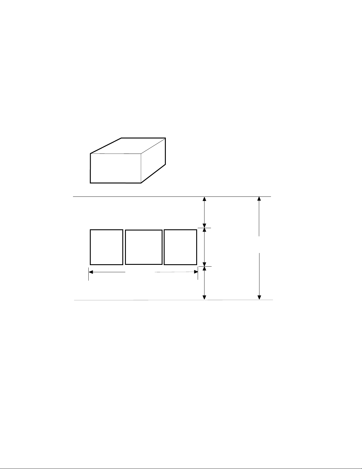
1.5 Prepare Area, Kits, and Tools
Set up a work space near the system where you can store
components, upgrade kits, and modules while you work on
the system upgrade. Prepare the system for shutdown.
Figure 1–3: System Space Requirements
H9657-CU
UPGRADE KIT
46.2 CM (18.5 IN)
68.8 CM (27.5 IN)
70 CM (28.0 IN)
REAR
CLEARANCE
1 M (39 IN)
TAPE
CABINET
SYSTEM
CABINET
WIDTH
1.9 M (74 IN)
DISK
CABINET
1–10 VAX 6000 XMI Conversion Manual
.9 M
(36 IN)
FRONT
CLEARANCE
1 M (39 IN)
DEPTH
2.9 M (114 IN)
msb-0119A-90

1. Prepare an area near the system where you can place system
components during the upgrade.
2. Perform an orderly shutdown of the system.
3. Turn the upper key switch on the front control panel to the Off (0)
position.
4. Pull the circuit breaker on the AC power controller to the Off position.
The AC power controller is at the bottom rear of the cabinet.
5. Unplug system power cord; wait 2 minutes for capacitors to discharge.
6. Using a Phillips screwdriver, remove the ground straps from the doors.
Remove the doors from the cabinet and set them aside.
7. Remove the screws and drop the I/O bulkhead tray to expose the card
cages.
8. As you work, save all screws that you remove.
Table 1–3: Tools and Supplies Required
Item Description
VAXBI tool kit
A2-M1094-10
Other tools 3/8", 5/16", and 11/32" nutdrivers, pliers, 7/16" socket wrench, flash-
ESD boxes Antistatic boxes; correct box for each module to be removed from the
Torque screwdriver, 11/32" nutdriver, large Phillips and flat screwdrivers, small Phillips screwdriver with magnetic tip
light
XMI-1 card cage
Specifications and Preparation 1–11

1.6 Unpacking Checklist
Carefully unpack the full power and packaging upgrade kit
(H9657-CU). Check the contents against Table 1–4. If any
components are missing, note items on the bill of lading and
do not start installation until you receive all components.
Table 1–4: H9657-CU Platform Upgrade Components
Part Number Description
70-24902-02 14-slot XMI-2 card cage assembly
H7242-00 +3V regulator
H7206-B Power and logic unit
DWMBB-AB XMI-2 adapters for VAXBI; 2 required
20-29176-02 XTC module
17-02500-01 Power supply enable cable
17-02521-01 XMI-2 card cage to H405 cable
74-40932-01 Mounting plate for H7206 power and logic unit
12-28686-07 Shield, RFI (BeCU spring clips)
12-28686-10 Shield, RFI (BeCU spring clips)
12-28686-11 Shield, RFI (BeCU spring clips)
36-33598-01 XMI module utilization label
17-02522-01 H7242 inhibit cable
36-15946-01 Product change label
17-02759-01 Fail safe enable cable
1–12 VAX 6000 XMI Conversion Manual

Chapter 2
XMI-1 to XMI-2 Conversion
This chapter describes how to upgrade a VAX 6000 XMI-1 platform to a
VAX 6000 XMI-2 platform.
Sections include:
• Full Upgrade Procedure Overview
• Step 1, Remove the XMI-1 Card Cage
Prepare for Removal
Remove the XMI-1 Card Cage from the Cabinet
• Step 2, Remove the H7214 Power Regulator(s)
Replace the H7214 in Position 2, if Necessary
Remove the H7214 in Position 3
• Step 3, Install the H7242 Power Regulator
• Step 4, Install the XMI-2 Card Cage
Attach the Daughter Card and Install the Card Cage
Attach the XMI-2 Card Cage Cables
Complete XMI Cabling
• Step 5, Replace the XTC Power Sequencer
• Step 6, Remove the H7231-N Battery Backup Unit
• Step 7, Replace the Power and Logic Unit
Remove the H7206-A Power and Logic Unit
Replace the Power and Logic Unit Mounting Plate
Install the H7206-B Power and Logic Unit
Apply Power to Check Conversion
XMI-1 to XMI-2 Conversion 2–1
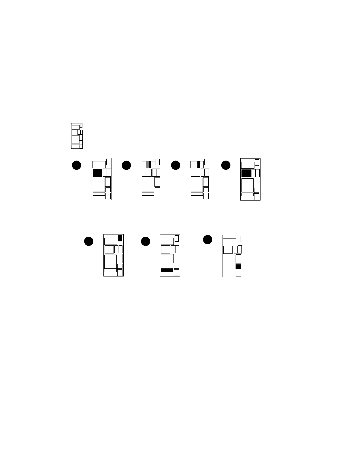
2.1 Full Upgrade Procedure Overview
Figure 2–1 shows the order of the upgrade procedure.
Detailed instructions follow.
Figure 2–1: Upgrade Overview
REAR
1
REMOVE THE
XMI CARD CAGE
5
REPLACE THE
XTC POWER
SEQUENCER
MODULE
2
REMOVE THE
H7214(s) POWER
REGULATOR(s)
6
3
INSTALL THE
H7242 POWER
REGULATOR
REMOVE BATTERY
BACKUP UNIT, IF
PRESENT
4
XMI CARD CAGE
7
INSTALL THE NEW
H7206-B POWER
AND LOGIC UNIT
INSTALL THE
3.3 VOLT
msb-0370-90
2–2 VAX 6000 XMI Conversion Manual

Figure 2–1 shows the optimal order for the full upgrade. The steps include:
1
The XMI-1 card cage must be removed first. This step requires two
people to guide the unit from the front and the back at the same time.
The daughter card from the XMI-1 card cage will be used on the XMI-2
card cage.
2
The H7214 power regulator above and to the right of the XMI card
cage is removed next. If the other XMI H7214 regulator is at A or B
revision level (120 amps), you also need to exchange this H7214 with a
C revision level or above (130 amps).
3
Install the H7242 +3.3V power regulator.
4
Install the XMI-2 card cage, after the daughter card from the XMI-1
card cage has been attached. This unit comes with preassembled bus
bars.
5
Replace the XTC power sequencer module, which is mounted on the
back of the system control assembly.
6
Remove the battery backup unit, if the system has one. To replace
the battery backup unit, follow the procedures described in VAX 6000:
Installing the H7236-A Battery Backup Option.
7
Replace the H7206-A power and logic unit with an H7206-B unit.
Three new cables are installed in the steps above. For cable information,
see Section 1.6.
XMI-1 to XMI-2 Conversion 2–3
2.2 Step 1, Remove the XMI-1 Card Cage
The XMI-1 card cage is removed from the front of the cabinet
after you disconnect cables from the backplane.
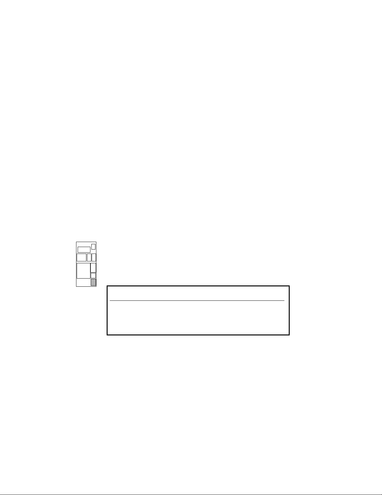
2.2.1 Prepare for Removal
Prepare the system for shutdown. Set up a work space
nearby where you can store the modules and work on the
XMI-1 card cage. Label and disconnect the signal and power
connections.
Figure 2–2: XMI-1 Backplane Cables and Power Connections
REAR
2–4 VAX 6000 XMI Conversion Manual
Product Conversion
From:
To: H9657-CU
By: Date:
DEC
36-15946-06-A01
msb-0686B-91

1. Perform an orderly shutdown of the system.
2. Turn the upper key switch on the front control panel to the Off position.
3. Pull the circuit breaker on the AC power controller to the Off position.
The AC power controller is at the bottom rear of the cabinet.
4. Unplug the system.
5. Open the rear cabinet door.
6. Remove the screws and drop the I/O bulkhead tray to expose the card
cages.
NOTE: Figure 2–2 shows the end to disconnect for each of the following
cables.
7. Disconnect all I/O adapter cables from the XMI-1 card cage. See7in
Figure 2–2.
8. Loosen the 5/16 inch nut on the H7215 cable retainer bracket. Swing
the bracket to one side.
9. Disconnect the power supply cable (17-01566-01) from J3 of the H7215
power regulator. See9.
10. If present, remove the plastic covers over the power connections on the
H7214 power regulators. To do this, remove the three 5/16 inch nuts
that connect each cover to the back of a regulator.
11. Disconnect the power connections from the H7214 power regulators.
(On each regulator, remove the four screws from the leads.) See11.
12. Disconnect the remote sense wires (17-01525-01) from the H7214 power
regulators. (Remove connector J4 from the regulator.) See12.
XMI-1 to XMI-2 Conversion 2–5
 Loading...