

Page 1

VAX 6000: Installing the
VAXBI Option
Order Number EK–60BIA–IN–001
This manual is intended for Digital customer service
engineers and self-maintenance customers installing
the VAXBI option or the TK tape drive option. The
VAXBI option includes the VAXBI card cages, power
regulators, the DWMBB adapter, and cables.
digital equipment corporation
maynard, massachusetts
Page 2
First Printing, February 1991
The information in this document is subject to change without notice and should not be
construed as a commitment by Digital Equipment Corporation.
Digital Equipment Corporation assumes no responsibility for any errors that may appear in
this document.
The software, if any, described in this document is furnished under a license and may be used
or copied only in accordance with the terms of such license. No responsibility is assumed
for the use or reliability of software or equipment that is not supplied by Digital Equipment
Corporation or its affiliated companies.
Copyright ©1991 by Digital Equipment Corporation.
All Rights Reserved.
Printed in U.S.A.
The following are trademarks of Digital Equipment Corporation:
DEMNA PDP VAXcluster
DEC ULTRIX VAXELN
DEC LANcontroller UNIBUS VMS
DECnet VAX XMI
DECUS VAXBI
dt
FCC NOTICE: The equipment described in this manual generates, uses, and may emit
radio frequency energy. The equipment has been type tested and found to comply with the
limits for a Class A computing device pursuant to Subpart J of Part 15 of FCC Rules, which
are designed to provide reasonable protection against such radio frequency interference when
operated in a commercial environment. Operation of this equipment in a residential area
may cause interference, in which case the user at his own expense may be required to take
measures to correct the interference.
Page 3

Contents
Preface vii
Chapter 1 Specifications and Preparation
1.1 VAXBI Option Description ........................... 1–2
1.2 Prepare Area, Kit, and Tools . . . ...................... 1–4
1.3 Unpacking Checklist . .............................. 1–6
Chapter 2 Installing the VAXBI Option
2.1 Remove the Baffle Assembly . . . ...................... 2–2
2.2 Install the VAXBI Assembly.......................... 2–4
2.2.1 Disengage the System Control Assembly . ............. 2–4
2.2.2 Insert the VAXBI Assembly . . ...................... 2–6
2.2.3 Cable the VAXBI Assembly . . ...................... 2–8
2.3 Install the H7214 Power Regulator .................... 2–10
2.4 Install the H7215 Power Regulator .................... 2–12
2.5 Install the DWMBB Modules . . . ...................... 2–14
Chapter 3 Acceptance and Troubleshooting
3.1 Restore Power to System ............................ 3–2
3.2 Check Self-Test Results ............................. 3–4
3.3 VAXBI Troubleshooting ............................. 3–6
3.4 H7206-B Diagnostic LEDs ........................... 3–8
iii
Page 4

Chapter 4 Installing the TK70 Tape Drive Option
4.1 TK70 Tape Drive Option Description ................... 4–2
4.2 Install the TK Tape Drive ........................... 4–4
4.2.1 Attach the Tape Drive Housing ..................... 4–4
4.2.2 Prepare the Cabinet and Remove the Filler Bezel . . ..... 4–6
4.2.3 Cable the TK Tape Drive .......................... 4–8
4.2.4 Install the TBK70 Module . . . ...................... 4–10
4.3 Check the TK Tape Drive Load Path ................... 4–12
Appendix A TK70 Tape Drive Instructions
A.1 Controls and Indicators ............................. A–2
A.2 Loading a Tape ................................... A–3
A.3 Unloading a Tape.................................. A–4
A.4 Write-Protecting Your Tape Cartridge .................. A–4
A.5 Labeling a Tape Cartridge ........................... A–5
A.6 Tape Handling and Storage Guidelines ................. A–5
Index
Examples
4–1 TK ROM-Based Diagnostic .......................... 4–12
Figures
1–1 VAXBI Card Cage Connections . ...................... 1–2
1–2 Overview of VAXBI Installation . ...................... 1–3
1–3 System Space Requirements . . . ...................... 1–4
2–1 Baffle Assembly ................................... 2–2
2–2 System Control Assembly (Front View) ................. 2–4
2–3 System Control Assembly (Rear View) .................. 2–5
2–4 VAXBI Card Cages . . . .............................. 2–6
2–5 VAXBI Backplane Cables and Power Connections ......... 2–8
2–6 H7214 Power Regulator (Rear View) ................... 2–10
2–7 H7215 Power Regulator (Rear View) ................... 2–12
iv
Page 5

2–8 VAX 6000 Series Slot Numbers . ...................... 2–14
3–1 AC Power Controller Circuit Breaker .................. 3–2
3–2 Self-Test Results .................................. 3–4
3–3 H7206-B Diagnostic LEDs ........................... 3–8
4–1 TK70 Tape Drive Location ........................... 4–2
4–2 Tape Drive Housing . . .............................. 4–4
4–3 Filler Bezel Removal . .............................. 4–6
4–4 Plate Removal and TK70 Tape Drive Connectors.......... 4–8
4–5 Numbering of VAXBI Slots........................... 4–10
A–1 TK Tape Drive .................................... A–2
A–2 TK Tape Cartridge . . . .............................. A–4
Tables
1 VAX 6000 Series Documentation ...................... viii
2 VAX 6000 Model Level Documentation ................. ix
3 Associated Documents .............................. x
1–1 Tools Required .................................... 1–5
1–2 VAXBI Option Kit . . . .............................. 1–6
2–1 VAXBI Assembly Cables to Be Installed . . . ............. 2–9
3–1 VAXBI Troubleshooting Checklist ..................... 3–6
3–2 VAXBI Connector Cleaning Supplies ................... 3–7
3–3 H7206-B LEDs .................................... 3–9
4–1 TK70 Tape Drive Option Kit . . . ...................... 4–3
4–2 TK Tape Drive Cables to Be Installed .................. 4–9
A–1 TK70 Light Summary .............................. A–3
v
Page 6

Preface
Intended Audience
This manual is written for Digital customer service engineers and selfmaintenance customers who install the VAXBI option or the TK tape drive
option.
Document Structure
This manual uses a structured documentation design. There are many
topics, organized into small sections for efficient reference. Each topic
begins with an abstract. You can quickly gain a comprehensive overview
by reading only the abstracts. Next is an illustration or example, which
also provides quick reference. Last in the structure is descriptive text.
This manual has four chapters and one appendix, as follows:
• Chapter 1, Specifications and Preparation, gives an overview of
the VAXBI option, including specifications.
• Chapter 2, Installing the VAXBI Option, gives instructions on
how to install and cable the VAXBI card cage assembly, the DWMBB
modules, and the power regulators in the system cabinet.
• Chapter 3, Acceptance and Troubleshooting, describes the
acceptance procedure.
• Chapter 4, Installing the TK Tape Drive Option, gives instructions
on how to install and cable the TK tape drive.
• Appendix A, TK70 Tape Drive Instructions, gives instructions on
how to operate the tape drive.
vii
Page 7
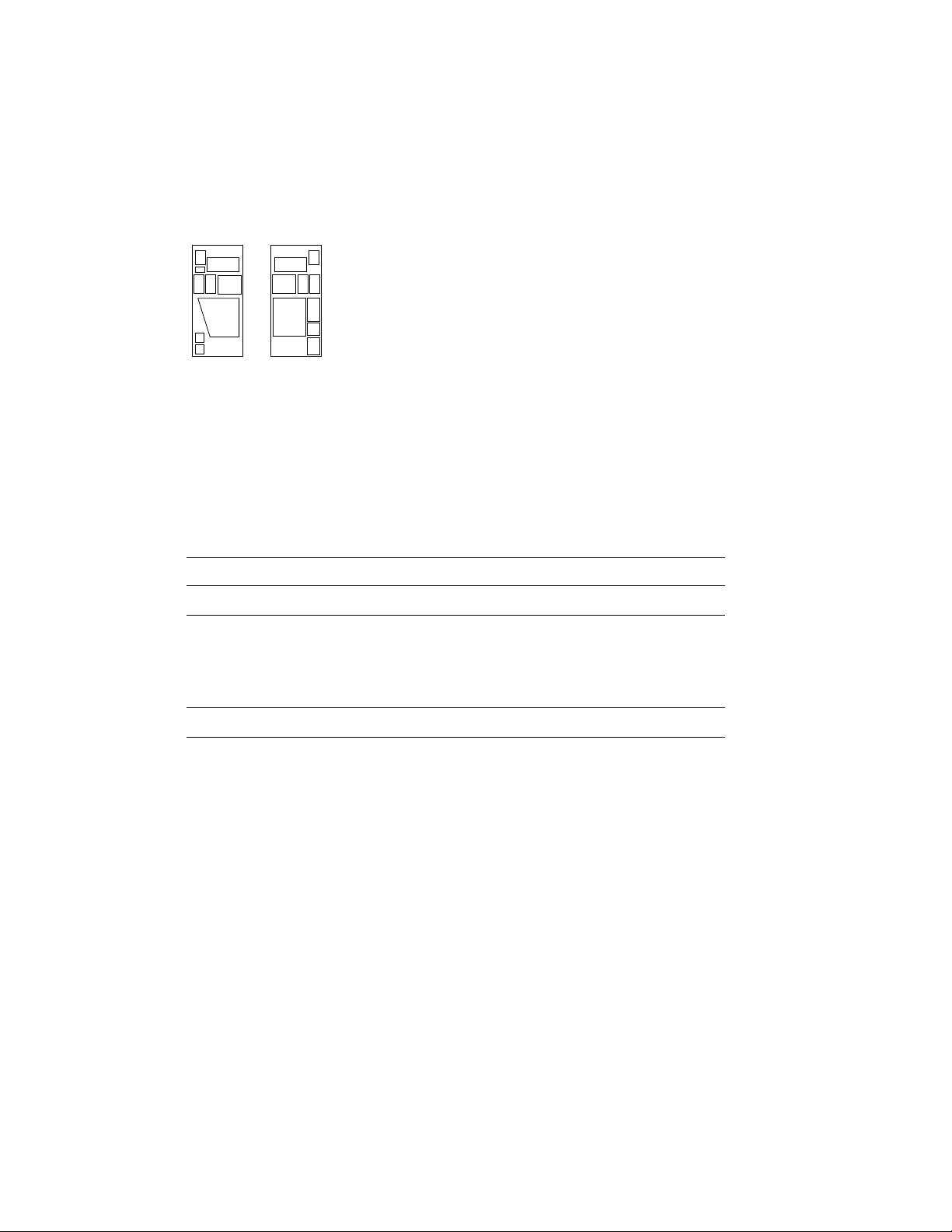
Conventions Used in This Document
The icons shown below are used in illustrations for designating part
placement in VAX 6000 series systems. A shaded area in the icon shows
the location of the component or part being discussed.
FRONT
REAR
VAX 6000 Series Documents
There are two sets of documentation: manuals that apply to all VAX 6000
series systems and manuals that are specific to one VAX 6000 model.
Table 1 lists the manuals in the VAX 6000 series documentation set.
Table 1: VAX 6000 Series Documentation
Title Order Number
Operation
VAX 6000 Series Owner’s Manual EK–600EA–OM
VAX 6000 Series Vector Processor Owner’s Manual EK–60VAA–OM
VAX 6000 Vector Processor Programmer’s Guide EK–60VAA–PG
Service and Installation
VAX 6000 Platform Technical User’s Guide EK–600EA–TM
VAX 6000 Series Installation Guide EK–600EA–IN
VAX 6000 Installationsanleitung EK–600GA–IN
VAX 6000 Guide d’installation EK–600FA–IN
VAX 6000 Guia de instalacion EK–600SA–IN
VAX 6000 Platform Service Manual EK–600EA–MG
viii
Page 8

Table 1 (Cont.): VAX 6000 Series Documentation
Title Order Number
Options and Upgrades
VAX 6000: XMI Conversion Manual EK–650EA–UP
VAX 6000: Installing MS65A Memories EK–MS65A–UP
VAX 6000: Installing the H7236-A Battery Backup Option EK–60BBA–IN
VAX 6000: Installing the FV64A Vector Option EK–60VEA–IN
VAX 6000: Installing the VAXBI Option EK–60BIA–IN
Manuals specific to models are listed in Table 2.
Table 2: VAX 6000 Model Level Documentation
Title Order Number
Models 200/300/400
VAX 6000 Model 300 and 400 Service Manual EK–624EA–MG
VAX 6000: Installing Model 200/300/400 Processors EK–6234A–UP
Model 500
VAX 6000 Model 500 Mini-Reference EK–650EA–HR
VAX 6000 Model 500 Service Manual EK–650EA–MG
VAX 6000 Model 500 System Technical User’s Guide EK–650EA–TM
VAX 6000: Installing Model 500 Processors EK–KA65A–UP
Associated Documents
Table 3 lists other documents that you may find useful.
ix
Page 9

Table 3: Associated Documents
Title Order Number
System Hardware Options
VAXBI Expander Cabinet Installation Guide EK–VBIEA–IN
VAXBI Options Handbook EB–32255–46
System I/O Options
CIBCA User Guide EK–CIBCA–UG
CIXCD Interface User Guide EK–CIXCD–UG
DEC LANcontroller 200 Installation Guide EK–DEBNI–IN
DEC LANcontroller 400 Installation Guide EK–DEMNA–IN
InfoServer 100 Installation and Owners Guide EK–DIS1K–IN
KDB50 Disk Controller User’s Guide EK–KDB50–UG
KDM70 Controller User Guide EK–KDM70–UG
RRD40 Disc Drive Owner’s Manual EK–RRD40–OM
RA90/RA92 Disk Drive User Guide EK–ORA90–UG
SA70 Enclosure User Guide EK–SA70E–UG
SA70/6000 Cabinet Series Upgrade Installation Guide EK–SA7CK–IN
Operating System Manuals
Guide to Maintaining a VMS System AA–LA34A–TE
Guide to Setting Up a VMS System AA–LA25A–TE
Introduction to VMS System Management AA–LA24A–TE
ULTRIX–32 Guide to System Exercisers AA–KS95B–TE
VMS Upgrade and Installation Supplement: VAX 6000 Series AA–LB36C–TE
VMS Networking Manual AA–LA48A–TE
VMS System Manager’s Manual AA–LA00A–TE
VMS VAXcluster Manual AA–LA27B–TE
x
Page 10

Table 3 (Cont.): Associated Documents
Title Order Number
Peripherals
HSC Installation Manual EK–HSCMN–IN
H4000 DIGITAL Ethernet Transceiver Installation Manual EK–H4000–IN
Installing and Using the VT320 Video Terminal EK–VT320–UG
RV20 Optical Disk Owner’s Manual EK–ORV20–OM
SC008 Star Coupler User’s Guide EK–SC008–UG
TA78 Magnetic Tape Drive User’s Guide EK–OTA78–UG
TA90 Magnetic Tape Subsystem Owner’s Manual EK–OTA90–OM
TK70 Streaming Tape Drive Owner’s Manual EK–OTK70–OM
TU81/TA81 and TU/81 PLUS Subsystem User’s Guide EK–TUA81–UG
VAX Manuals
VAX Architecture Reference Manual EY–3459E–DP
VAX Systems Hardware Handbook — VAXBI Systems EB–31692–46
VAX Vector Processing Handbook EC–H0739–46
xi
Page 11

Chapter 1
Specifications and Preparation
This chapter describes the VAXBI option and gives preparation guidelines
for installing the VAXBI option in a VAX 6000 cabinet. Chapter 2 describes
the installation. If you are also installing the TK70 tape drive option, see
Chapter 4 for that installation procedure. Sections in this chapter include:
• VAXBI Option Description
• Prepare Area, Kit, and Tools
• Unpacking Checklist
Specifications and Preparation 1–1
Page 12
1.1 VAXBI Option Description
The VAXBI assembly can be installed to provide additional
I/O. The two cages provide a single VAXBI channel. The
interface between the VAXBI bus and the XMI bus is the
DWMBB adapter. The DWMBB/A module is in the XMI card
cage, and the DWMBB/B module is in the VAXBI card cage.
Figure 1–1: VAXBI Card Cage Connections
H7215 H7214
XMI
VAXBI
CHASSIS
I/O DEVICES
msb-0108A-90
1–2 VAX 6000: Installing the VAXBI Option
Page 13
The three major components you will install are the VAXBI assembly, the
H7214 power regulator, and the H7215 power regulator.
Figure 1–2: Overview of VAXBI Installation
REAR
ADD
H7215
ADD
H7214
ADD VAXBI
CARD CAGE
ASSEMBLY
msb-0736-91
Specifications and Preparation 1–3
Page 14
1.2 Prepare Area, Kit, and Tools
Set up a work space near the system where you can store
components and modules while you work on the VAXBI
option installation. Some steps in this installation require
two people. Prepare the system for shutdown.
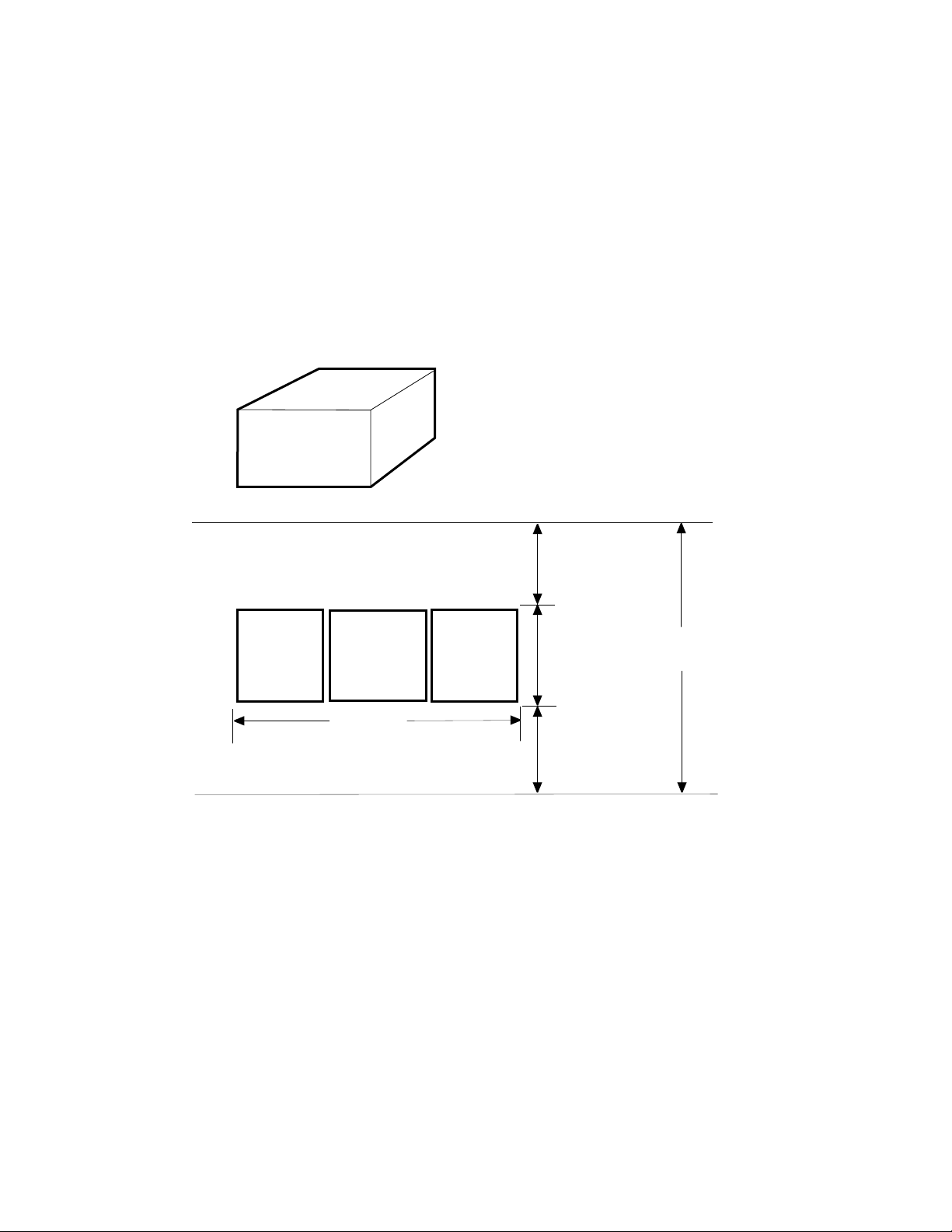
Figure 1–3: System Space Requirements
VAXBI OPTION
KIT
57 CM (22 IN)
73 CM (28.8 IN)
72 CM (28.0 IN)
REAR
CLEARANCE
1 M (39 IN)
TAPE
CABINET
SYSTEM
CABINET
WIDTH
1.9 M (74 IN)
DISK
CABINET
1–4 VAX 6000: Installing the VAXBI Option
.9 M
(36 IN)
FRONT
CLEARANCE
1 M (39 IN)
DEPTH
2.9 M (114 IN)
msb-0119B-91
Page 15

1. Prepare an area near the system where you can place system
components during the installation.
2. Perform an orderly shutdown of the system.
3. Turn the upper key switch on the front control panel to the Off position.
4. Pull the circuit breaker on the AC power controller to the Off position.
The AC power controller is at the bottom rear of the cabinet.
5. Unplug the system power cord; wait 2 minutes for the capacitors to
discharge.
6. Open the front and rear cabinet doors. Using a Phillips screwdriver,
remove the ground straps from the doors. Remove the doors from the
cabinet and set them aside.
7. Remove the two Phillips screws and drop the I/O bulkhead tray to
expose the card cage area.
8. As you work, save all screws that you remove.
Table 1–1: Tools Required
Item Description
VAXBI Tool Kit
A2-M1094-10
Other tools 3/8" and 5/16" nutdrivers, 7/16" socket wrench, flashlight
Torque screwdriver, 11/32" nutdriver, large Phillips and flat screwdrivers, small Phillips screwdriver with magnetic tip
Specifications and Preparation 1–5
Page 16

1.3 Unpacking Checklist
Carefully unpack the VAXBI option kit (DWMBB-D-DBP).
Check the contents against Table 1–2. If any components
are missing, note items on the bill of lading and do not start
installation until you receive all components.
Table 1–2: VAXBI Option Kit
Part Number Description
70-24126-02 VAXBI card cage assembly
H7214-A Power regulator
H7215-A Power regulator
T2018-00 DWMBB/A module
T1043-00 DWMBB/B module
17-01458-02 VAXBI ground strap
17-01569-01 DWMBB to H7206 power OK signal cable
17-01897-02 7" DWMBB I/O cables (two pairs)
74-35973-01 Cable retainer
74-35974-01 H7214 cover
36-33598-02 VAXBI module utilization label
36-12680-02 Ground symbol labels
EK-60BIA-IN VAX 6000: Installing the VAXBI Option
1–6 VAX 6000: Installing the VAXBI Option
Page 17

Chapter 2
Installing the VAXBI Option
This chapter describes the installation of the VAXBI assembly into a VAX
6000 cabinet. Sections include:
• Remove the Baffle Assembly
• Install the VAXBI Assembly
• Install the H7214 Power Regulator
• Install the H7215 Power Regulator
• Install the DWMBB Modules
Installing the VAXBI Option 2–1
Page 18
2.1 Remove the Baffle Assembly
Remove the baffle assembly installed in the VAXBI space.
The assembly directs the airflow when the VAXBI card cages
are not present.
Figure 2–1: Baffle Assembly
FRONT
21
2–2 VAX 6000: Installing the VAXBI Option
msb-0735-91
Page 19

1. Remove the clear plastic door in front of the VAXBI area.
2. Peel and stick on the VAXBI label beneath the mounting bracket (see
!
in Figure 2–1).
3. Using a flat screwdriver, remove two screws in front and slide the baffle
assembly out of the cabinet (see"). Remove the two screws at the top of
the VAXBI area. Save these four screws to attach the VAXBI assembly
to the cabinet.
Installing the VAXBI Option 2–3
Page 20

2.2 Install the VAXBI Assembly
Tilt the system control assembly upward to allow clearance
for the VAXBI assembly. Then slide the VAXBI assembly into
the cabinet. Finally, make the necessary cable connections.
NOTE: This step requires two people. One person must tilt the
system control assembly upward to allow for clearance while the
other person slides the VAXBI assembly into the cabinet.
2.2.1 Disengage the System Control Assembly
Working from the front and rear of the cabinet, remove the
six mounting screws and slide the system control assembly
forward.
Figure 2–2: System Control Assembly (Front View)
2
2
2
msb-0064B-90
2–4 VAX 6000: Installing the VAXBI Option
Page 21

1. At the rear of the cabinet, loosen the two mounting screws that secure
the system control assembly to the cabinet side (see!in Figure 2–3).
2. At the front of the cabinet, loosen the four mounting screws (see"in
Figure 2–2). Remove three screws and, supporting the system control
assembly with one hand, remove the last loosened screw with your
hand. Using both hands, carefully pull the system control assembly
forward until you are able to tilt it upward.
Figure 2–3: System Control Assembly (Rear View)
1
msb-0066C-91
Installing the VAXBI Option 2–5
Page 22

2.2.2 Insert the VAXBI Assembly
Working at the front of the cabinet, insert the VAXBI
assembly while the system control assembly is tilted up to
allow for clearance. This step requires two people.
Figure 2–4: VAXBI Card Cages
2
FRONT
2
2–6 VAX 6000: Installing the VAXBI Option
msb-0116B-90
Page 23

1. Slide the VAXBI assembly into the cabinet taking care not to damage
the power harnesses or bus bars. Youwill also need to pull the assembly
from the back.
2. Install a mounting screw in the upper left corner of the VAXBI assembly
(see"in Figure 2–4). Then carefully slidethe system control assembly
into the cabinet. Install the three remaining mounting screws that
secure the VAXBI assembly to the cabinet.
3. Reinstall the six Phillips screws that secure the system control
assembly to the cabinet (see Section 2.2.1).
Installing the VAXBI Option 2–7
Page 24

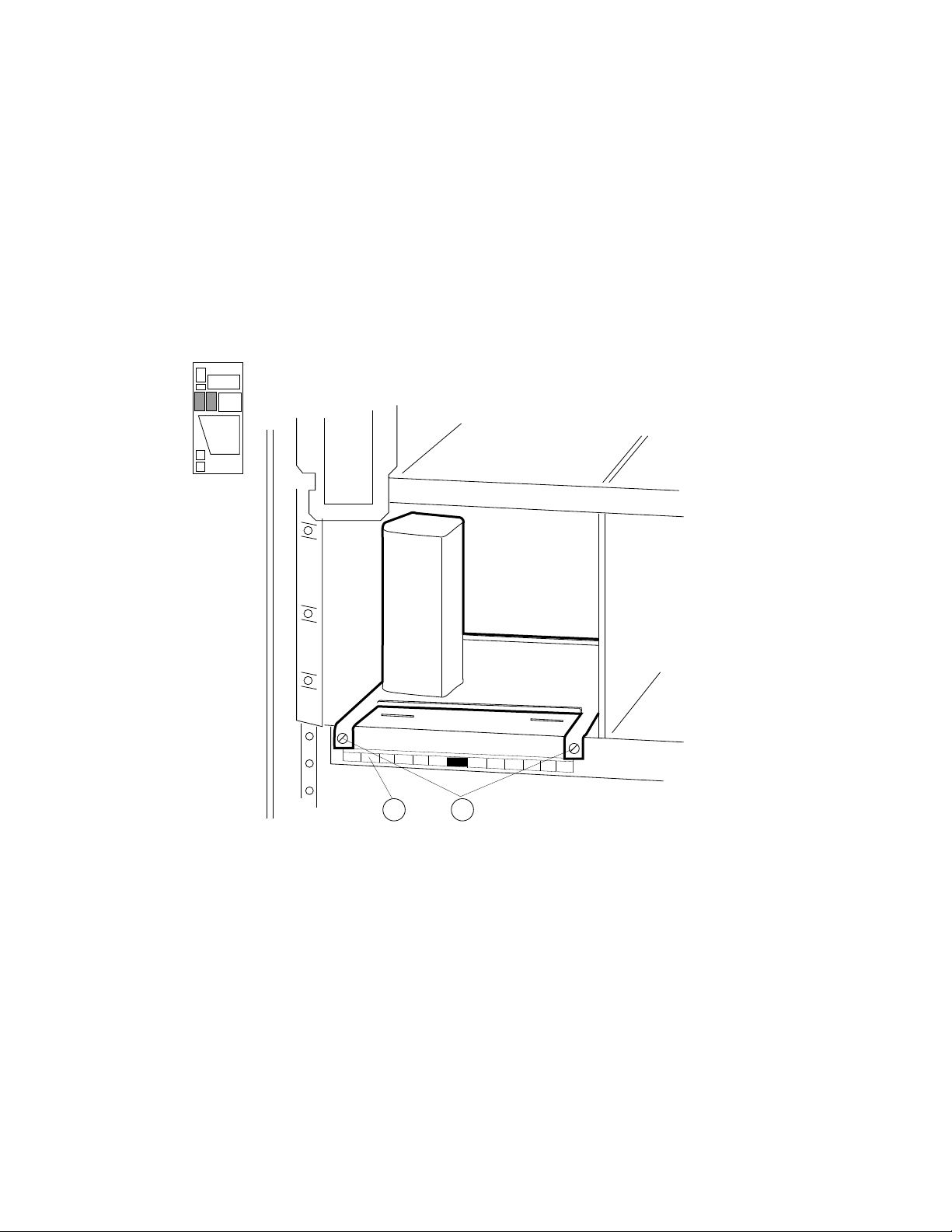
2.2.3 Cable the VAXBI Assembly
Working mainly from the rear of the cabinet, install the
three cables that are in the VAXBI option kit.
Figure 2–5: VAXBI Backplane Cables and Power Connections
2
3
msb-0112C-90
1
2–8 VAX 6000: Installing the VAXBI Option
Page 25

1. Install the 17-01458-02 ground strap to the VAXBI assembly (see!in
Figure 2–5) using a nutdriver and kepnut. Fasten the filter end of the
cable near the assembly bus bars with the lug pointed upward. Fasten
the other end of the ground strap to the chassis above.
2. Install the 17-01569-01 cable. At the front of the cabinet, connect the
cable to J11 on the H7206-B power and logic unit. J11 is located on
the right side of the unit and is the third connector from the front.
Route the cable directly to the VAXBI backplane and connect it to slot
1, segment C1 (see").
3. Install the two pairs of DWMBB cables (17-01897-02) between the
VAXBI and XMI cages (see#). These cables connect XMI slot E
segments D and E with the nearest VAXBI card cage (slot 1, segments
D and E).
NOTE: You will install the DWMBB/A module into slot E of the XMI
card cage. If another module is in slot E, it mustbe removedand inserted
into the next open XMI slot.
Table 2–1: VAXBI Assembly Cables to Be Installed
Part Number Description
17-01458-02 VAXBI ground strap. Connects the VAXBI backplane to the cab-
17-01569-01 DWMBB to H7206 power OK signal cable. Connects from slot 1, seg-
17-01897-02 7" DWMBB cables (two pairs), from XMI slot E (segments D and
inet chassis.
ment C1, to J11 of H7206-B.
E) to VAXBI cage slot 1 (segments D and E).
Installing the VAXBI Option 2–9
Page 26

2.3 Install the H7214 Power Regulator
Working mainly from the rear of the cabinet, install the
H7214 power regulator. Attach the cables. For reference,
check the H7214 power regulator that is already installed in
the cabinet.
Figure 2–6: H7214 Power Regulator (Rear View)
1
6
3
2
5
4
3
1
msb-0076B-90
2–10 VAX 6000: Installing the VAXBI Option
Page 27

NOTE: Check the H7214 power regulator before installing. The H7214
ground reference wire is connected to the regulator’s circuit board and return
bus bar by a screw and a washer. Make sure the wire is intact and properly
connected. Tuck the wire out of the way when inserting the regulator into
the cabinet.
From the rear of the system cabinet:
1. Slide the H7214 power regulator into the far right end of the power
regulator area. Tighten the four slotted screws (see!in Figure 2–6).
Remove the protective covering from the H7214.
2. Connect the bus bar leads (attached to the VAXBI assembly) by
installing four screws. See". The black bus bar lead connects to
RTN. The red bus bar lead connects to +5V.
CAUTION: You must use 5/16 inch screws. If you use the longer 7/16
inch screws, the power regulators may short out.
3. Find the 74-35974-01 plastic cover. Using a 5/16 inch nutdriver, install
the cover with three nuts. See#.
4. Connect the 17-01525-01 remote sense cable to J4. See$. (The remote
sense cable is part of the power harness.)
5. Connect the 17-01666-01 control/status cable to J1. See%.
6. If you are installing an Ethernet, connect the +13.5V cord (part of 1701496-01) to J2. See&.
7. Working from the front of the cabinet, use a slotted screwdriver to
tighten the captive screw to the H7214 power regulator.
8. The 17-01447-01 bulk power cable is clamped to the cabinet top.
Release the cable and plug both ends into the power regulator
connectors.
Installing the VAXBI Option 2–11
Page 28

2.4 Install the H7215 Power Regulator
Working mainly from the rear of the cabinet, install the
H7215 power regulator. For reference, check the H7215
power regulator that is already installed in the cabinet.
Figure 2–7: H7215 Power Regulator (Rear View)
6
5
3
4
2
msb-0078B-90
2–12 VAX 6000: Installing the VAXBI Option
Page 29

From the rear of the system cabinet:
1. Disconnect the 2-pin Mate-N-Lock connector to the Interlock switch.
The connector is located at the bottom of the regulator space.
2. Slide the H7215 power regulator in to the left of the H7214. Reconnect
the 2-pin Mate-N-Lock connector. See"in Figure 2–7.
3. Using a flat screwdriver, tighten the two screws at the top and bottom
of the regulator. See#.
4. Connect the 10-pin connector (part of the control/status cable) to J2.
See$.
5. Connect the 32-pin power distribution cable (17-01523-01) to J3. See
%
. This connector is keyed.
6. Using a 5/16 inch nutdriver, attach the cable retainer (74-35973-01)
with a nut. See&.
7. At the front of the cabinet, use a slotted screwdriver to tighten the
captive screw to the H7215 power regulator.
Installing the VAXBI Option 2–13
Page 30

2.5 Install the DWMBB Modules
Install the DWMBB modules. The DWMBB/A module is
installed in the XMI card cage; the DWMBB/B module is
installed in the VAXBI card cage.
Figure 2–8: VAX 6000 Series Slot Numbers
VAXBI CARD CAGE
12 11 10 9 8 7 6 5 4 3 2 1
XMI CARD CAGE
E D C B A 9 8 7 6 5 4 3 2 1
msb-0040B-90
2–14 VAX 6000: Installing the VAXBI Option
Page 31

NOTE: You will install the DWMBB/A module into slot E of the XMI card
cage. If another module is in slot E, it must be removed and inserted into
the next open XMI slot.
At the front of the cabinet:
1. Remove the clear plastic door in front of the XMI card cage.
CAUTION: You must wear an antistatic wrist strap attached to the
cabinet when you handle any modules.
2. Install the DWMBB/B module (T1043) in slot 1 of the VAXBI (see
Figure 2–8).
3. Install the DWMBB/A module (T2018) in slot 14 (or E) of the XMI card
cage.
4. Insert any other modules into the VAXBI card cages.
5. Mark the position of each module on the VAXBI label.
6. Replace and latch the XMI and VAXBI clear plastic doors.
Installing the VAXBI Option 2–15
Page 32

Chapter 3
Acceptance and Troubleshooting
This chapter discusses the acceptance procedure and troubleshooting
guidelines for the VAXBI option. See the VAX 6000 Platform Service
Manual for more information on troubleshooting. Sections include:
• Restore Power to System
• Check Self-Test Results
• VAXBI Troubleshooting
• H7206-B Diagnostic LEDs
Acceptance and Troubleshooting 3–1
Page 33

3.1 Restore Power to System
Close up the cabinet and restore power systematically
before turning the key switch to the Enable position.
Figure 3–1: AC Power Controller Circuit Breaker
REAR
ON
OFF
3–2 VAX 6000: Installing the VAXBI Option
msb-0405-90
Page 34

1. Close the I/O bulkhead tray to cover the card cages.
2. Rehang and close the front and rear cabinet doors.
3. Plug in the system power cord.
4. Push the circuit breaker on the AC power controller to the On position.
The AC power controller is at the bottom rear of the cabinet. See
Figure 3–1.
5. Turn the upper key switch on the front control panel to the Enable
position; the system should power up and run self-test. If the system
does not power up, check to see that all modules are seated properly in
the card cages.
6. If the self-test results print, but you have self-test failures, see
Section 3.2.
Acceptance and Troubleshooting 3–3
Page 35

3.2 Check Self-Test Results
Check the self-test results to see if all XMI and VAXBI nodes
passed. The self-test printout contains an additional line
when the optional VAXBI adapter is part of the system
configuration. The XBI line provides information on the
node numbers and self-test status for modules in the VAXBI
card cages.
Figure 3–2: Self-Test Results
#123456789 0123456789 0123456789 0123456789 012345#
F E D C B A 9 8 7 6 5 4 3 2 1 0 NODE #
A A . . M M M M . . P P P P TYP
1
o + . . + + + + . . + + + + STF
2
. . . . . . . . . . E E E B BPD
. . . . . . . . . . + + + + ETF
. . . . . . . . . . E E E B BPD
. . . . . . + + . + . + - + + . XBI E +
. . . . A4 A3 A2 A1 . . . . . . ILV
. . . . 64 64 64 64 . . . . . . 256 Mb
3
Console = V2.00 RBDs = V2.00 EEPROM = 2.00/2.00 SN = SGO1234567
>>>
3–4 VAX 6000: Installing the VAXBI Option
msb-0701H-91
Page 36

The system configuration shown in Figure 3–2 has a DWMBB adapter.
!
The TYP line in this printout indicates that adapters in this
configuration are in XMI slots D and E.
"
Because the DWMBB adapter does not have a module-resident self-test,
its entry for the STF line will always be "o".
#
The test results for the DWMBB/A and DWMBB/B modules are
indicated on the XBI line, at the far right. In this example, the DWMBB
modules have passed self-test (XBI E +). The results of the VAXBI I/O
adapter self-tests are shown in columns 0 through F, which stand for
the VAXBI node numbers; in this configuration, node numbers 1, 2, 3,
4, 6, 8, and 9 are used. The adapter at node 3 failed its self-test. If you
receive failures within a VAXBI card cage, check the cabling and then
run diagnostics for the respective modules, if needed.
When a DWMBB passes self-test, each node on that VAXBI is indicated
by symbols + and –, indicating the self-test status for that node number
on the VAXBI. A period (.) indicates that that node number is not used.
When a DWMBB fails self-test, the failure is reported, and the VAXBI
device self-tests are not displayed.
XMI entries use slots 1 through E, while the VAXBI can have entries in
slots 0 through F. An XMI slot and node number are the same; VAXBI slot
and node numbers are not identical. Node plugs (labeled 1 to 12) in the
VAXBI backplane are used to identify the number of a node.
Acceptance and Troubleshooting 3–5
Page 37

3.3 VAXBI Troubleshooting
Check the items listed in Table 3–1 if the system fails to
power up.
Table 3–1: VAXBI Troubleshooting Checklist
Symptom Possible Cause
No power to cages Clear plastic door not in place or not latched.
Intermittent module response Poor contact at connector
Loose cabling at backplane
Power connector attached with 7/16" screw instead of 5/16"
screw
Module does not appear on selftest results
Loose cabling at backplane
System not configured correctly
3–6 VAX 6000: Installing the VAXBI Option
Page 38

Clear plastic doors cover the VAXBI and XMI card cages. If these doors are
opened when power is still on, a power interlock switch cuts off power from
the regulators to either the VAXBI side or to the XMI side, depending on
the door opened.
Before turning power back on, make sure the clear plastic doors are in place
and latched. You can then push the reset switch on the H7206-B power and
logic unit (see Figure 3–3) to return power to the system.
If you receive intermittent module response, or the module does not show
up on self-test as being present at all, make sure the module is seated
properly, a node ID plug is in place, and the backplane cabling is correct.
Modules may fail self-test because of poor contact at the connector. A
thorough cleaning of the gold pads on the module and of the connector
in the card cage corrects this contact failure. If the connections seem to be
faulty, clean the contact areas of the connector and module. Table 3–2 lists
tools and supplies for connector cleaning.
Table 3–2: VAXBI Connector Cleaning Supplies
Item
VAXBI tool kit A2-M1094-10 Maintaining card cages
Paddle wipe handle 47-00116-02 Holding paddle wipes
Paddle wipes 12-26321-01 Cleaning contact area inside ZIF connec-
Gold-wipes™ 49-01603-00 Cleaning module connector contact area
Protective goggles 29-16141-10 Eye protection
Nitrile gloves 29-26403-00 Hand protection
™Gold-wipes is a trademark of TEXWIPE.
Part
Number Function
tors
Acceptance and Troubleshooting 3–7
Page 39

3.4 H7206-B Diagnostic LEDs
The H7206-B power and logic unit has one green and eight
red LEDs in the upper righthand corner and a larger green
LED in the lower lefthand corner.
Figure 3–3: H7206-B Diagnostic LEDs
FRONT
9
8
7
6
RED
LEDs
5
4
3
2
1
GREEN
LED
J1
14V BIAS
LED
3–8 VAX 6000: Installing the VAXBI Option
RESET
SWITCH
Page 40

The H7206-B power and logic unit has 10 indicator LEDs and one reset
switch.
The nine LEDs in the upper right corner of the H7206-B are explained in
Table 3–3. Refer to Figure 3–3 for LED numbering.
The green +14V bias LED lights to indicate when the bias supply on the
fan/power module is working.
WARNING: When the +14V bias LED is off, do not assume that the bulk
supply is deenergized. This LED does not indicate the presence or absence
of the 300V bulk supply.
Table 3–3: H7206-B LEDs
LED Color Meaning
9 Red Fault (airflow, interlock, overtemperature)
8 Red XMI-1 module in XMI-2 card cage
7 Red H7214 or H7242 installed incorrectly
6 Red VAXBI—H7214 fault
5 Red VAXBI—H7215 fault
4 Red XMI—H7242 fault
3 Red XMI—H7214 fault
2 Red XMI—H7215 fault
1 Green +14V logic bias is okay
LEDs 2 through 6 are latched on to indicate regulator faults. Reset these
LEDs by turning the key switch to Off and back to Enable or Standby, or
by pressing the reset switch (see Figure 3–3). LEDs 5 and 6 are always lit
in Standby mode, since the VAXBI side is off in this key position.
The H7206-B LEDs may not indicate problems with regulators if the status
cables are not correctly seated.
Acceptance and Troubleshooting 3–9
Page 41

Chapter 4
Installing the TK70 Tape Drive Option
This chapter describes the installation of a TK70 tape drive into a VAX
6000 cabinet. Operating instructions are given in Appendix A.
Sections include:
• TK70 Tape Drive Option Description
• Install the TK Tape Drive
• Check the TK Tape Drive Load Path
Installing the TK70 Tape Drive Option 4–1
Page 42

4.1 TK70 Tape Drive Option Description
The TK70 tape drive can be installed to provide an in-cabinet
console load device. The TBK70 adapter is the interface
between the tape drive and the VAXBI. The tape drive is
installed in the system control assembly in the upper left
front of the cabinet.
Figure 4–1: TK70 Tape Drive Location
FRONT
TK70
TAPE DRIVE
ASSEMBLY
4–2 VAX 6000: Installing the VAXBI Option
msb-0069A-90
Page 43

Table 4–1 lists the items in the TK70 tape drive option kit.
Table 4–1: TK70 Tape Drive Option Kit
Part Number Description
TK70-AA Tape drive
74-41495-01 Tape drive housing
T1035-00 TBK70 controller
17-02833-01 Signal cable, from tape drive to system control assembly
17-02632-01 Signal cable, from system control assembly to VAXBI back-
EK-60BIA-IN VAX 6000: Installing the VAXBI Option
plane
Installing the TK70 Tape Drive Option 4–3
Page 44

4.2 Install the TK Tape Drive
First, attach the tape drive housing to the tape drive.
Next remove the plastic filler bezel from the system control
assembly. Then install and cable the tape drive. Insert the
TBK70 module into the VAXBI card cage. You will need a
small Phillips screwdriver and a flat screwdriver.
4.2.1 Attach the Tape Drive Housing
Attach the housing to the tape drive with four Phillips
screws.
Figure 4–2: Tape Drive Housing
3
2
4–4 VAX 6000: Installing the VAXBI Option
msb-0738-91
Page 45

1. Place the housing over the tape drive, as shown in Figure 4–2. The
captive screw on the housing should be at the front of the tape drive,
on the right side.
2. Using a small Phillips screwdriver, install the two flathead Phillips
screws on the left side of the tape drive (see"in Figure 4–2).
3. Install the two panhead Phillips screws on the right side of the tape
drive (see#).
Installing the TK70 Tape Drive Option 4–5
Page 46

4.2.2 Prepare the Cabinet and Remove the Filler Bezel
Turn off the system and remove the filler bezel.
Figure 4–3: Filler Bezel Removal
FRONT
msb-0070B-91
4–6 VAX 6000: Installing the VAXBI Option
Page 47

1. Turn the system control panel upper key switch to the Off position.
2. Open the front door of the cabinet.
3. Remove the filler bezel from the system control assembly. The bezel is
held in place by one slotted screw (see#in Figure 4–3).
Installing the TK70 Tape Drive Option 4–7
Page 48

4.2.3 Cable the TK Tape Drive
Remove the metal plate from the system control assembly.
Then connect the cables and insert the TK tape drive into
the system control assembly. There are two signal cables
and one power cable.
Figure 4–4: Plate Removal and TK70 Tape Drive Connectors
2
4
5
4–8 VAX 6000: Installing the VAXBI Option
msb-0741-91
Page 49

1. Open the rear door of the cabinet.
2. Locate the small metal plate at the right of the power sequencer module
(see"in Figure 4–4). Remove the plate by removing two screws.
3. Take the 17-02833-01 ribbon cable from the kit and on the large
connector, remove one screw and loosen one screw. When installing,
make sure the retaining clips are positioned to go through the opening
made by removing the metal plate in Step 2.
From the front of the cabinet, push the connector through the opening.
Make sure that the red line on the cable is at the bottom of the cable.
Using a small Phillips screwdriver, install the two connector screws.
Thread the other end of the cable through the cable guide toward the
front of the cabinet.
4. Connect the other end of the 17-02833-01 cable into the TK drive at the
top left (see$).
5. Plug the 4-wire power connector into the bottom left of the TK drive
(see%). The power cable is already in the system control assembly.
6. Slide the tape drive into the opening, being careful not to twist the
signal cable.
As you push the unit in, hold the signal cable flush to the left side of
the unit so that it remains untangled and is installed smoothly. Tuck
the end loop in if it protrudes when the TK unit is installed.
7. Tighten the captive screw on the left side of the tape drive.
8. At the rear of the cabinet, connect the 17-02632-01 cable to the system
control assembly (this cable connects to the 17-02833-01 connector
installed in Step 3). Push the retaining clips down to lock into place.
Table 4–2: TK Tape Drive Cables to Be Installed
Part Number Description
17-02632-01 Ribbon cable, from the system control assembly to the VAXBI slot of
17-02833-01 Ribbon cable, from the tape drive to the system control assem-
the TBK70 module, segment D2.
bly.
4-wire power cord, from system control assembly to tape drive.
Installing the TK70 Tape Drive Option 4–9
Page 50

4.2.4 Install the TBK70 Module
Next install the TBK70 module into the VAXBI card cage.
Then connect the signal cable to the VAXBI backplane.
Figure 4–5: Numbering of VAXBI Slots
12 11 10 9 8 7 6 5 4 3 2 1
msb-0716-90
4–10 VAX 6000: Installing the VAXBI Option
Page 51

CAUTION: You must wear an antistatic wrist strap attached to the cabinet
when you handle any modules.
1. Remove the plastic door in front of the VAXBI card cage. Install the
TBK70 module into the desired VAXBI slot. Replace the door.
2. At the rear of the cabinet, route the 17-02632-01 signal cable (red stripe
down) to the VAXBI slot that holds the TBK70 module. Insert the
connector into segment D2. Thread the extra cable up through the
cable clamp.
3. Close the front and rear cabinet doors.
4. Turn the system control panel upper key switch to the Enable position.
Installing the TK70 Tape Drive Option 4–11
Page 52

4.3 Check the TK Tape Drive Load Path
In console mode, you can use the Z command to "attach" to
the TK controller on the VAXBI. Run a ROM-based test to
verify that the load path works properly. Return the console
to the boot processor.
Example 4–1: TK ROM-Based Diagnostic
!
>>> SHOW CONFIGURATION
Type Rev
1+ KA64A (8082) 0007
2+ KA64A (8082) 0007
3+ KA64A (8082) 0007
4+ KA64A (8082) 0007
7+ MS65A (4001) 0084
8+ MS65A (4001) 0084
9+ MS65A (4001) 0084
A+ MS65A (4001) 0084
D+ DEMNA (0C03) 0600
E+ DWMBB/A (2002) 0001
XBI E
1+ DWMBB/B (2002) 0001
2+ CIBCA (0108) 41C1
4+ TBK70 (410B) 0307
#
>>> Z/BI:4 E
?33 Z connection successfully started.
$
T/R
%
RBD4> D2/TR/T=6/C
;T1035_TK 1.00
;T06
&
;P
;00000000 00000000 00000000 00000000 00000000 00000000 00000000
'
RBD4> QUIT
(
^P
?31 Z connection terminated by ^P
>>>
6 410B 00000001
"
"
4–12 VAX 6000: Installing the VAXBI Option
Page 53

!
Put a blank cartridge in the TK drive. Make sure it is not writeprotected. The blank tape is required for proper running of the TK
RBDs. (If you are unfamiliar with the TK, see the VAX 6000 Series
Owner’s Manual.)
"
In this example, the DWMBB adapter is XMI node E. The TK controller
(TBK70) is VAXBI node 4.
#
Enter the Z command, using the /BI qualifier. The system console
communicates with the module at VAXBI node 4 on the VAXBI whose
adapter is at XMI node E. The system responds to the Z command with
a message.
$
Enter the command T/R to invoke the module’s ROM-based diagnostic
monitor.
%
The diagnostic monitor prompt is RBD4>, where 4 is the VAXBI node
number. Enter the command D2/TR/T=6/C. The diagnostic performs a
read/write test.
&
The diagnostic prints out several lines of information. Check for a P
in the first field of the diagnostic completion message, which indicates
that the test passed.
'
Enter QUIT, which stops execution of the ROM diagnostic monitor and
resets the controller.
(
Enter CTRL/P, which reattaches the console to the boot processor. The
system responds to CTRL/P with a message.
Installing the TK70 Tape Drive Option 4–13
Page 54

Appendix A
TK70 Tape Drive Instructions
The TK70 tape drive holds one tape cartridge that contains the magnetic
tape on a single reel. When a tape cartridge is inserted, the tape is
automatically threaded onto a reel inside the drive. The tape must be
entirely rewound before the cartridge can be removed from the drive.
Rewinding can take up to 90 seconds.
The TK70 can read data from a tape that was written by a TK50, but it
cannot overwrite a tape originally written by a TK50. A TK50, however,
cannot read data from a tape written by a TK70.
TK70 Tape Drive Instructions A–1
Page 55

A.1 Controls and Indicators
The TK70 tape drive has three lights, a beeper, an unload button, and a
cartridge insert/release handle. Table A–1 lists the functions of TK tape
drive controls and indicators that are shown in Figure A–1.
Figure A–1: TK Tape Drive
FRONT
ORANGE:
WRITE PROTECTED
Write
Protected
YELLOW:
TAPE IN USE
Tape in Use
TK70
To Load
* Wait Light
* Open this
* Insert Tape
To Unload
* Press Button
* Wait Light
* Open this
Remove Tape
Handle
* Close this
Handle
Handle
Operate
Handle
GREEN:
OPERATE HANDLE
Unload
UNLOAD
BUTTON
A–2 VAX 6000: Installing the VAXBI Option
msb-0183A-91
Page 56

Table A–1: TK70 Light Summary
Light State Condition
Green
(Operate Handle)
Yellow
(Tape in Use)
Orange
(Write Protected)
All three lights Blinking Drive fault. Attempt to reset the fault by press-
1
1
The orange light is on when any of the following conditions exist:
Cartridge write protect switch is in the protected position.
Cartridge is software write protected.
Attempt was made to mount or initialize a cartridge previously written in a TK50 drive.
On
Off
Blinking
Steady
Blinking
On
Off
OK to operate handle.
Do not operate handle.
Defective cartridge. Pull the handle to the open position and remove cartridge. Try another cartridge.
Drive ready.
Drive in use.
Tape write protected.
Tape write enabled.
ing the unload button.
A.2 Loading a Tape
To load a tape, follow these steps:
1. When the green light is on steadily,pull the handle to the open position.
2. With the label facing out, insert the tape cartridge.
3. Push the cartridge in until it is completely inside the drive.
4. Push the handle to the closed position. The yellow light blinks,
indicating that the tape is loading. When the yellow light stays on
steadily, the drive is ready for use.
NOTE: If the green light blinks or if all three lights blink, the loading has
failed.
TK70 Tape Drive Instructions A–3
Page 57

A.3 Unloading a Tape
To unload a tape, follow these steps:
1. Press the unload button or execute an appropriate operating system
unload command. The yellow light blinks as the tape rewinds.
2. When the green light turns on and the beep sounds, pull the handle to
the open position. The cartridge will partially eject.
3. Remove the cartridge.
4. Push the handle to the closed position.
NOTE: If all three lights blink, the unload has failed.
A.4 Write-Protecting Your Tape Cartridge
Write-protectinga tape cartridge prevents accidental erasure of information
stored on the tape. To write-protect a tape, slide the tape’s write-protect
switch to the left so that the small orange rectangle is visible, as shown in
Figure A–2.
Figure A–2: TK Tape Cartridge
ORANGE
INDICATOR
A–4 VAX 6000: Installing the VAXBI Option
SLOT
WRITE
PROTECT
SWITCH
msb-0191-89
Page 58

A.5 Labeling a Tape Cartridge
To label your tape cartridge:
• Write your identifying information on the label. Note the recording
density: TK70 = 296 Mbytes.
• Put the label into the slot on the front of the cartridge. See Figure A–2.
• Use only the labels supplied with the tape cartridge. Stick-on labels
applied to the top, bottom, or sides of the cartridge can loosen and jam
or damage the tape drive.
• Write only on the label. Do not write on the tape cartridge with a pen
or pencil.
A.6 Tape Handling and Storage Guidelines
To add life to your tapes and protect data, follow these guidelines:
• Do not drop or bang the cartridge.
• Store tape cartridges upright in a dust-free environment.
• Keep tape cartridges away from direct sunlight, heaters, and other
sources of heat. Store tape cartridges in an even temperature between
10oand 40oC (50oto 104oF).
• Keep tape cartridges away from sources of electromagnetic interference,
such as terminals, motors, and video or X-ray equipment.
TK70 Tape Drive Instructions A–5
Page 59

Index
B
Baffle assembly, 2–2
C
Cables, 2–9, 4–9
Connector cleaning supplies, 3–7
D
Diagnostic monitor, 4–13
DWMBB
installation, 2–14
H
H7206-B diagnostic LEDs, 3–8
H7214 power regulator, 2–10
H7215 power regulator, 2–12
P
Preparation, 1–4
R
ROM–based diagnostic for TK tape
drive, 4–12
TK tape cartridge (Cont.)
labeling, A–5
write protecting, A–4
TK tape drive, 4–1 to 4–13, A–1 to
A–5
acceptance, 4–12
controls and indicators, A–2 to
A–3
loading a tape, A–3
unloading a tape, A–4
Tools required, 1–5
Troubleshooting, 3–6
V
VAXBI adapters
self-test, 3–5
VAXBI option kit contents, 1–6
VAXBI troubleshooting, 3–6 to 3–7
X
XMI-to-VAXBI adapter
self-test results, 3–5
S
Self-test results, 3–4 to 3–5
Site preparation, 1–4 to 1–5
T
TBK70 module installation, 4–10
TK option kit contents, 4–3
TK tape cartridge, A–1 to A–5
handling and storage, A–5
Index–1
 Loading...