

Digital Equipment VAX 4000 Model 500A, VAX 4000 Model 505A, VAX 4000 Model 600A, VAX 4000 Model 700A, VAX 4000 Model 705A Installation Manual

VAX4000
Model500A/505A/600A/700A/705A
Installation
Order Number: EK–493AB–IN. B01
Digital Equipment Corporation
Maynard, Massachusetts

First Edition, March 1990
Seventh Edition, July 1994
The information in this document is subject to change without notice and should not be construed
as a commitment by Digital Equipment Corporation.
Digital Equipment Corporation assumes no responsibility for any errors that may appear in this
document.
The software, if any, described in this document is furnished under a license and may be used or
copied only in accordance with the terms of such license. No responsibility is assumed for the use
or reliability of software or equipment that is not supplied by Digital Equipment Corporation or its
affiliated companies.
Restricted Rights: Use, duplication or disclosure by the U.S. Government is subject to restrictions
as set forth in subparagraph (c)(1)(ii) of the Rights in Technical Data and Computer Software clause
at DFARS 252.227–7013.
Copyright © Digital Equipment Corporation 1990, 1994. All Rights Reserved.
The Reader’s Comments form at the end of this document requests your critical evaluation to assist
in preparing future documentation.
The following are trademarks of Digital Equipment Corporation: CompacTape, CX, DDCMP, DEC,
DECconnect, DECdirect, DECnet, DECscan, DECserver, DECUS, DECwindows, DELNI, DEMPR,
DESQA, DESTA, DSRVB, DSSI, IVAX, KDA, KLESI, KRQ50, MicroVAX, MSCP, Q–bus, Q22–bus,
RA, RQDX, RV20, SA, SDI, ThinWire, TK, TMSCP, TQK, TS05, TU, VAX, VAX 4000, VAXcluster,
VAX DOCUMENT, VAXELN, VAXlab, VAXserver, VMS, VT, and the DIGITAL logo.
All other trademarks and registered trademarks are the property of their respective holders.
FCC NOTICE: The equipment described in this manual generates, uses, and may emit radio
frequency. The equipment has been type tested and found to comply with the limits for a Class A
computing device pursuant to Subpart J of Part 15 of FCC Rules, which are designed to provide
reasonable protection against such radio frequency interference.
Operation of the equipment in a residential area may cause interference, in which case the user
at his own expense will be required to take whatever measures may be required to correct the
interference.
Warning: The VAX 4000 Model 705A is a Class A product. In a domestic environment this product
may cause radio interference in which case the user may be required to take adequate measures.
Achtung! Der VAX 4000 Modell 705A ist ein Gerät der Funkstörgrenzwertklasse A. In
Wohnbereichen können bei Betrieb dieses Geräts Rundfunkstörngen auftreten, in welchen Fällen
der Benutzer für entsprechende Gegenmaßnahmen verantwortlich ist.
Attention! Le VAX 4000 modèle 705A est un produit de Classe A. Dans un environnement
domestique, ce produit risque de créer des interférences radioélectriques, il appartiendra alors à
l’utilisateur de prendre les mesures spécifiques appropriées.
S2578
This document was prepared using VAX DOCUMENT Version 2.1.

Contents
1 Verify Site Preparation . . . . . . . . . . . . . . . . . . . . . . . . . . . 1
2 Check the Shipment . . . . . . . . . . . . . . . . . . . . . . . . . . . . . . 2
3 Position the System . . . . . . . . . . . . . . . . . . . . . . . . . . . . . . 5
4 Open the System Doors . . . . . . . . . . . . . . . . . . . . . . . . . . . 6
5 Install the Console Terminal . . . . . . . . . . . . . . . . . . . . . . . 8
6 Set the System Controls . . . . . . . . . . . . . . . . . . . . . . . . . . . 10
7 Connect Additional Devices to the System . . . . . . . . . . . . . 16
7.1 Connecting Terminals and Serial Printers . . . . . . . . . . 19
7.2 Connecting Parallel Printers . . . . . . . . . . . . . . . . . . . . 23
7.3 Connecting Synchronous Modems . . . . . . . . . . . . . . . . 25
7.4 Connecting Asynchronous Modems . . . . . . . . . . . . . . . 29
7.5 Connecting to an Ethernet Network at the H3604
Console Module . . . . . . . . . . . . . . . . . . . . . . . . . . . . . . 33
7.5.1 Making a ThinWire Network Connection . . . . . . . . 34
7.5.2 Making a Standard Network Connection . . . . . . . . 38
7.6 Connecting to an Ethernet Network at the DESQA
Module . . . . . . . . . . . . . . . . . . . . . . . . . . . . . . . . . . . . . 40
7.6.1 Making a ThinWire Network Connection . . . . . . . . 41
7.6.2 Making a Standard Network Connection . . . . . . . . 46
8 Connect an Expander . . . . . . . . . . . . . . . . . . . . . . . . . . . . . 48
8.1 Connecting the Q–Bus Cables . . . . . . . . . . . . . . . . . . . 49
8.2 Connecting the DSSI Cable . . . . . . . . . . . . . . . . . . . . . 50
8.3 Connecting the KZQSA External Cable . . . . . . . . . . . . 53
8.4 Connecting the Power Control Bus Cable . . . . . . . . . . 55
8.5 Connecting the Ground Cable . . . . . . . . . . . . . . . . . . . 56
9 Connect the System Power Cable . . . . . . . . . . . . . . . . . . . . 56
10 Turn On the System and Select a Language . . . . . . . . . . . 58
11 Close the System Doors . . . . . . . . . . . . . . . . . . . . . . . . . . . 61
12 After Installation . . . . . . . . . . . . . . . . . . . . . . . . . . . . . . . . 62
iii

Index
iv

1 Verify Site Preparation
Caution
Review your system warranty. It may require that a Digital service
representative install your system to prevent damage to equipment or
software.
If you are installing a DSSI VAXcluster configuration, and you are a licensed
self-maintenance customer, you should be familiar with the contents of your DSSI
VAXcluster Installation and Troubleshooting manual.
Caution
If you are installing a DSSI configuration, to prevent system performance
degradation or data corruption caused by excessive ground offset voltages,
make sure your site power distribution system does not have any of the
grounding faults listed in your Site Preparation manual.
The installation instructions that follow assume:
• Your site meets all the requirements listed in the system Site Preparation
manual.
• All cables that you plan to connect to your system are in place and clearly
labeled.
Terminal data cables?
Telephone cables?
Network cables?
• You have the following tools (not included in your shipment).
Scissors
Flat-blade screwdriver
Phillips (cross-point) screwdriver
Adjustable wrench
Voltmeter calibrated for millivolts
1
2 Check the Shipment
1. Find the Product Delivery Document. It is inside or attached to one of the
shipping cartons.
TMTM
Digital Equipment Corporation
Customer Order No. Dec No.
Shipped To
Product Delivery Document
Invoice To
Documentation Issue Date
Product Delivery No.
MLO-007108
2
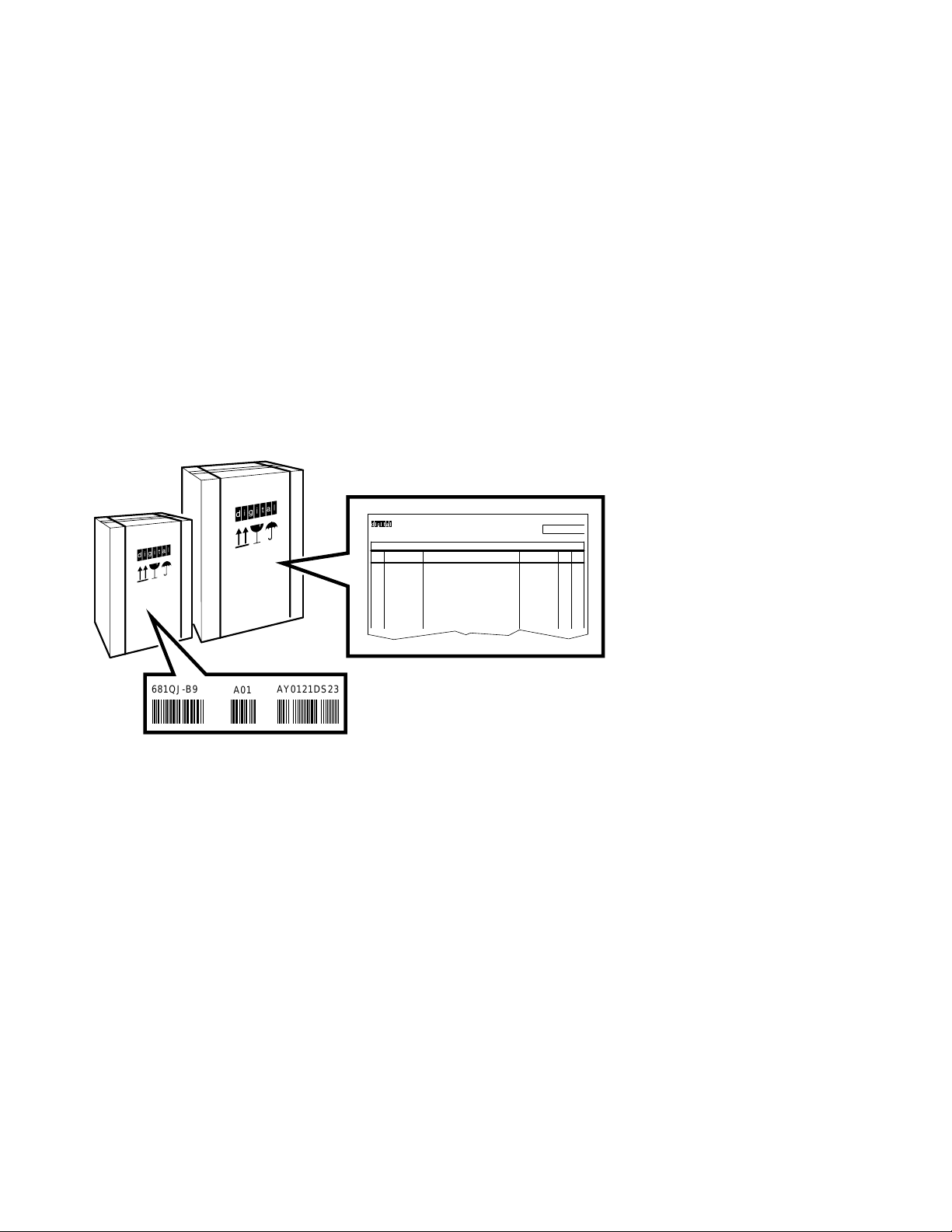
2. Make sure your shipment is complete by checking that each item listed as
shipped on the Product Delivery Document appears on a Content Listing or
on a Barcode Label on the outside of one of the cartons in your shipment.
681QJ-B9
A01
AY0121DS23
Line
Item
DEC NO.
TMTM
Model No.
Shipped
Content Listing
Description
Serial No.
Date:
Rev Qty
MLO-010176
A Content Listing may also be attached to a smaller container (bag or box)
packed inside a shipping carton.
3
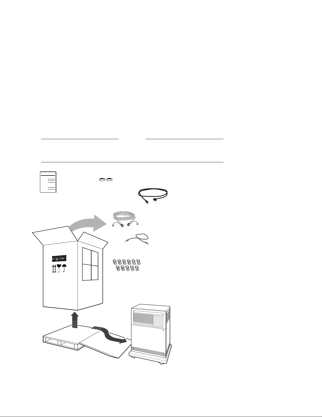
3. Use the unpacking illustrations on the cartons as a guide to unpack your
shipment.
Warning
The system weighs 68 kilograms (150 pounds) with all options installed.
To prevent personal injury, two or more people should move the system.
Customer
Hardware
Information Kit
Includes:
Installation Checklist
VMS FIS Guide
Anti Static
Anti Static
Keys to Front Door
Power Cable
Console Terminal Cable
(17-01364-02)
Ground Wire Cable
(12-13756-A8)
DSSI Bus Node ID Plugs
(12-28766-19)
KZQSA
Bus Node ID
Plugs
(12-28766-28)
System
Installation
Checklist
KZQSA
Internal Cable
(BC06P-2F)
Note:
Unpacking is illustrated on the
exterior of the shipping carton.
MLO-007181
4. Check the contents of each carton against the Content Listing to ensure you
received all items.
4
5. If any item is missing or damaged:
Contact your delivery agent.
Contact your Digital sales representative.
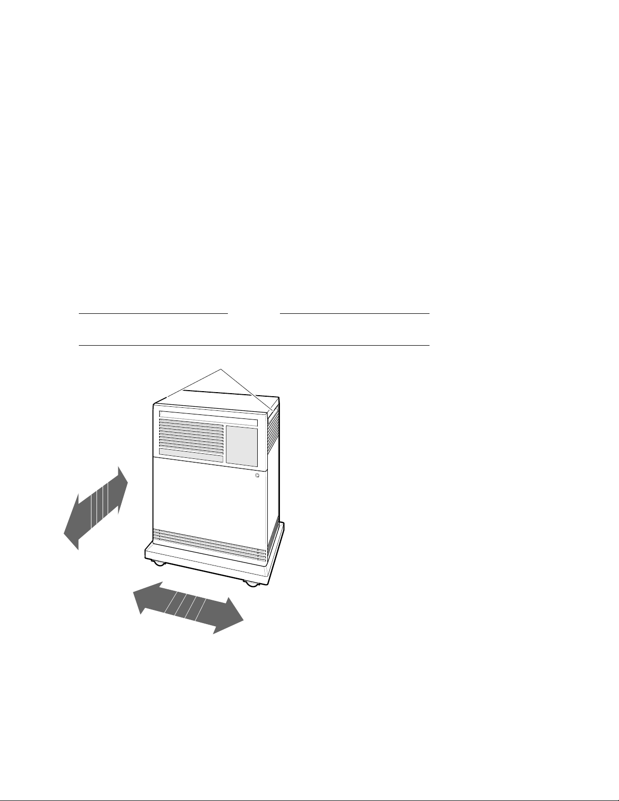
3 Position the System
Warning
To prevent personal injury, do not use the handholds to lift the system.
Hand Holds
Slides Front
to Back
Rolls Left to Right
MLO-004012
For now, leave space behind the system for routing cables.
5
4 Open the System Doors
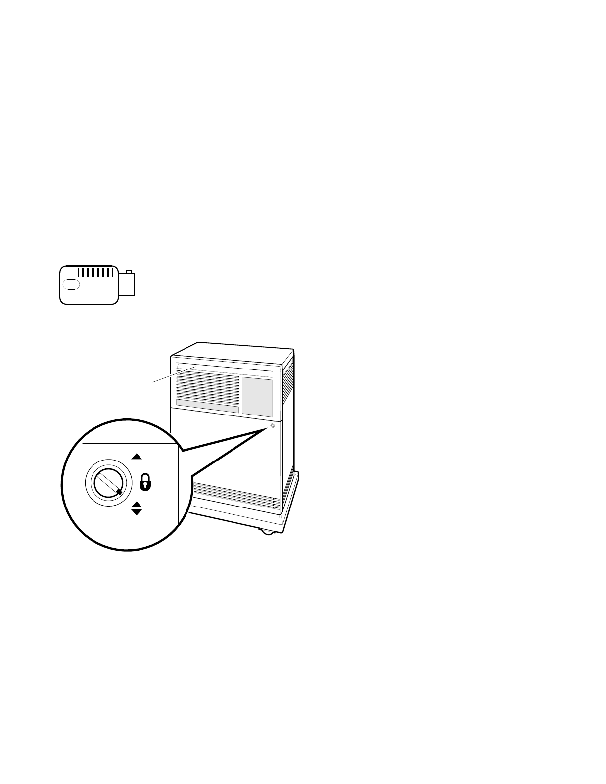
1. Find a key (two are provided).
Anti Static
MLO-007110
2. Insert that key in the rotary lock, and turn it to the bottom position.
Door Handle
Rotary Lock
MLO-007111
6

3. Open the doors by pulling the handle on the upper door.
MLO-004013
4. Review the meaning of the following warning symbols which appear on the
power supply.
Indicates a risk of electric shock.
To reduce the risk of injury, do not remove modules, Integrated
Storage Elements (ISEs), the tape drive, or the power supply. No
user-serviceable parts are inside. Refer servicing questions to your
Digital service representative or to your licensed self-maintenance
personnel.
7
5 Install the Console Terminal
1. Use the instructions in your terminal installation guide to connect the various
parts of the terminal.
2. Turn on the terminal.
3. After the terminal passes its self-test, perform the setup operations.
Be sure to:
• Read all the applicable documentation provided with your terminal.
• Follow the setup instructions for your terminal.
Note
A Digital terminal is shipped with the baud rate set to 9600. If you want
to use that rate, you can ignore the baud rate setup instructions.
4. Turn off the terminal.
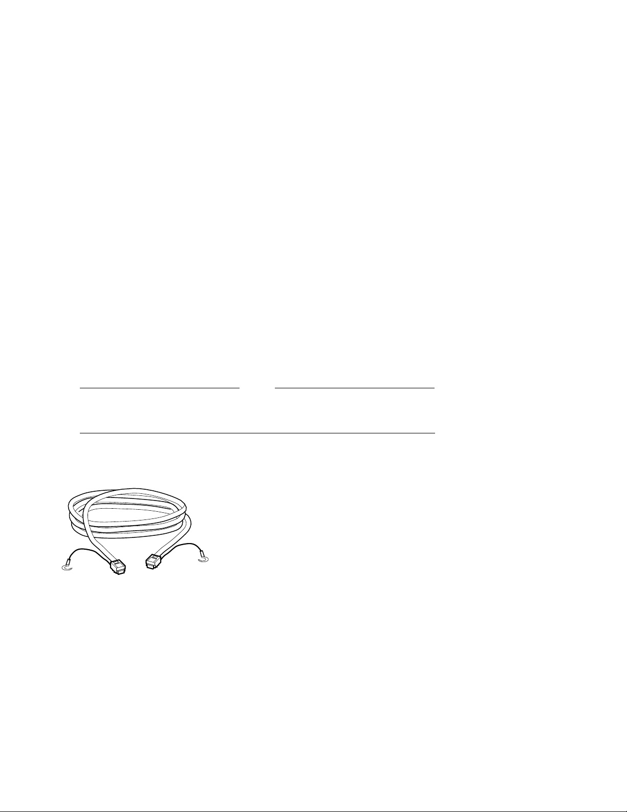
5. Find the console terminal cable.
MLO-007112
8
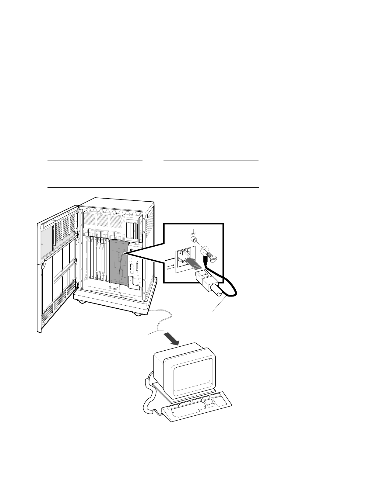
6. Connect the terminal cable to the modular jack on the rear of the terminal, as
described in your terminal installation guide.
Note
Shading in this and subsequent illustrations indicates the general location
of the connections you will make.
Ground
Lead
Terminal
Cable
MLO-007182
7. Insert the terminal cable into the modular jack on the system console module,
and connect the cable ground lead, as shown above.
9
6 Set the System Controls
1. Check the setting of the Power switch on the power supply. It should be off
(set at 0).
I
O
MLO-007113
10
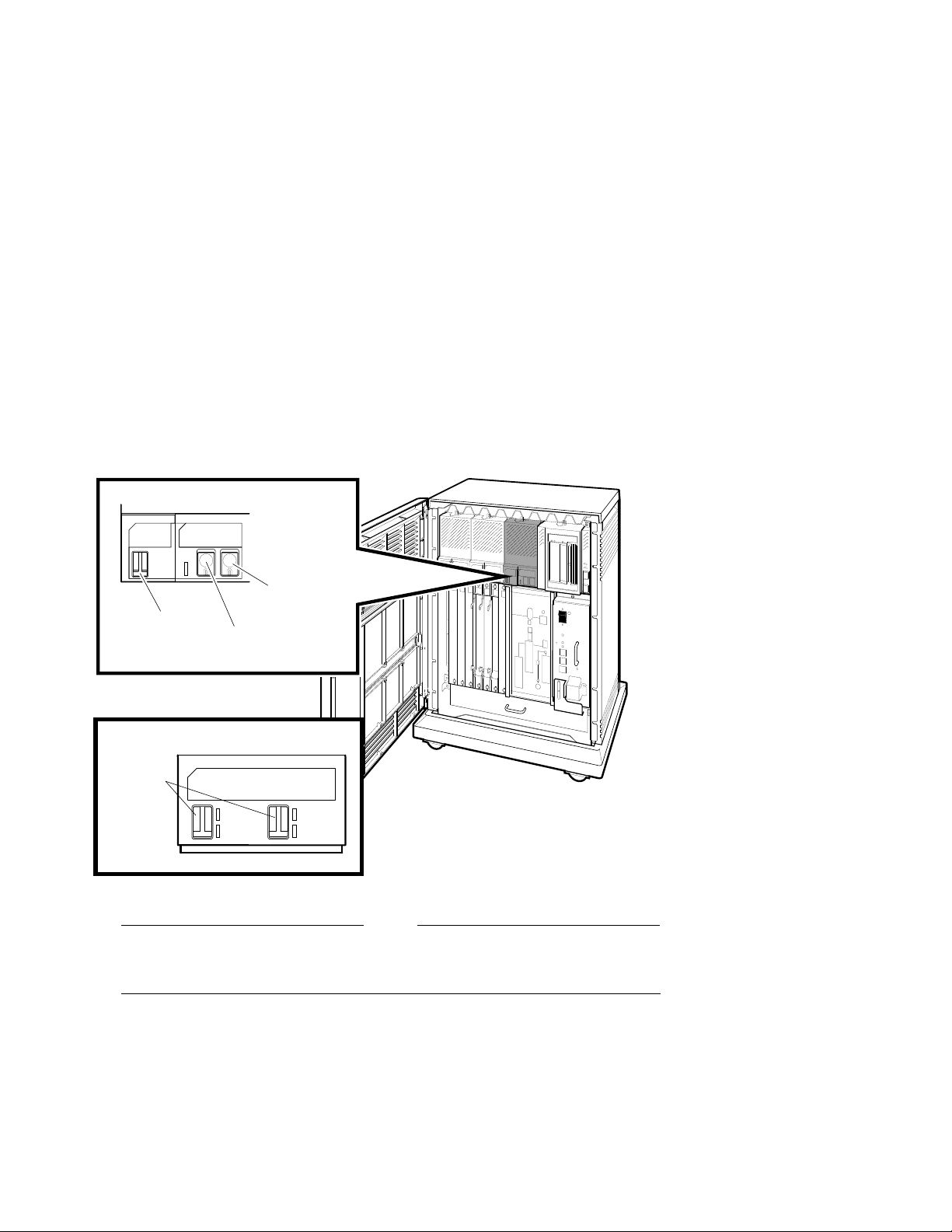
2. Check the settings on each Integrated Storage Element (ISE):
• The Write-Protect button should be out (write-enabled position).
• The Run/Ready button should be in (ready position).
• Verify that uniquely numbered bus node ID plugs are inserted into the
ISEs.
Write-Protect
Button
Bus Node
ID Plug
Bus Node
ID Plugs
Run/Ready
Button
OR
MLO-007702
Note
If a bus node ID plug is missing from an ISE, refer to your system
Operation manual for corrective action.
11
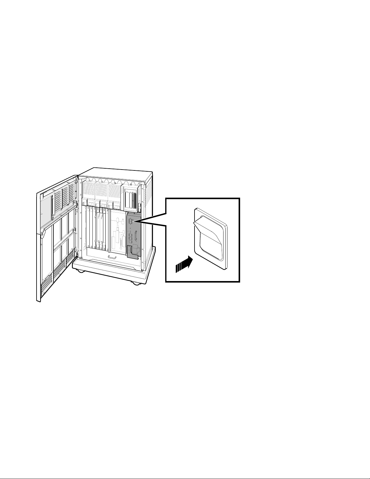
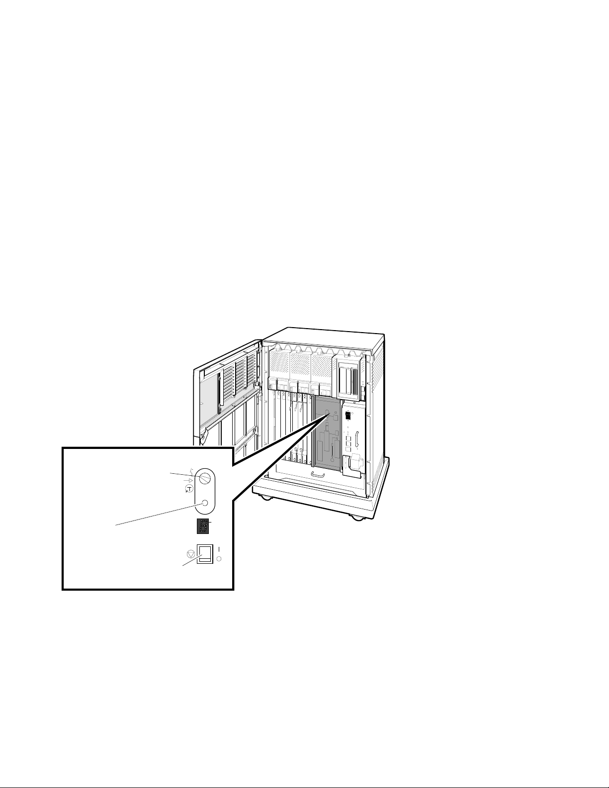
3. Check the setting of the Halt button on the system control panel. It should be
out (run position).
Halt Button
MLO-007115
12
4. Check the settings on the console module:
• The Power-Up Mode switch should be set to Language Inquiry (uppermost
position, indicated by a human profile).
• The Baud Rate Select switch should be set to the same rate you used for
your console terminal.
• The Break Enable/Disable switch should be set to break enabled (up,
indicated by a | ).
Power-Up
Mode Switch
Baud Rate
Select Switch
Baud
300___________0
600___________1
1200__________2
2400__________3
4800__________4
9600__________5
19200_________6
38400_________7
5
Break Enable/
Disable Switch
MLO-007116
13
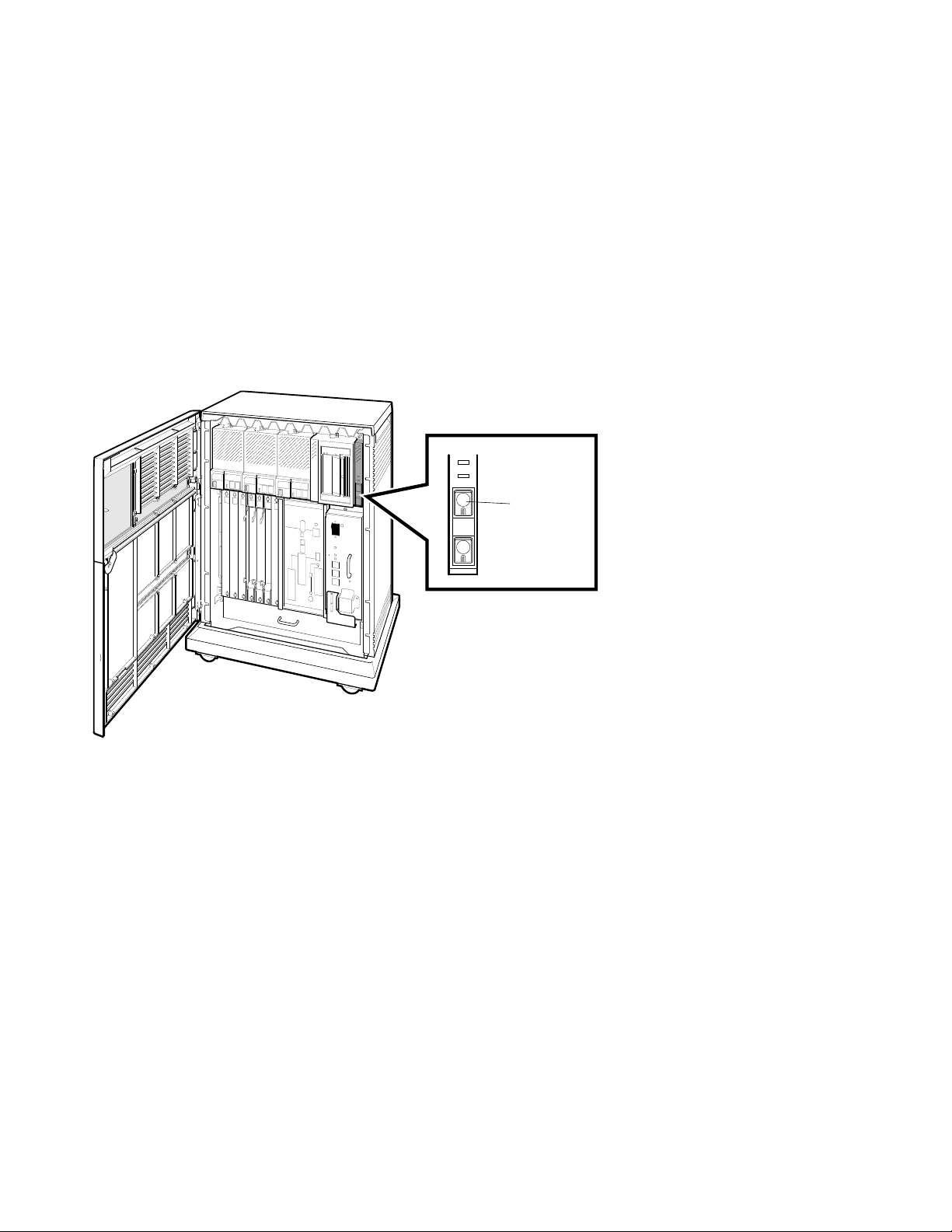
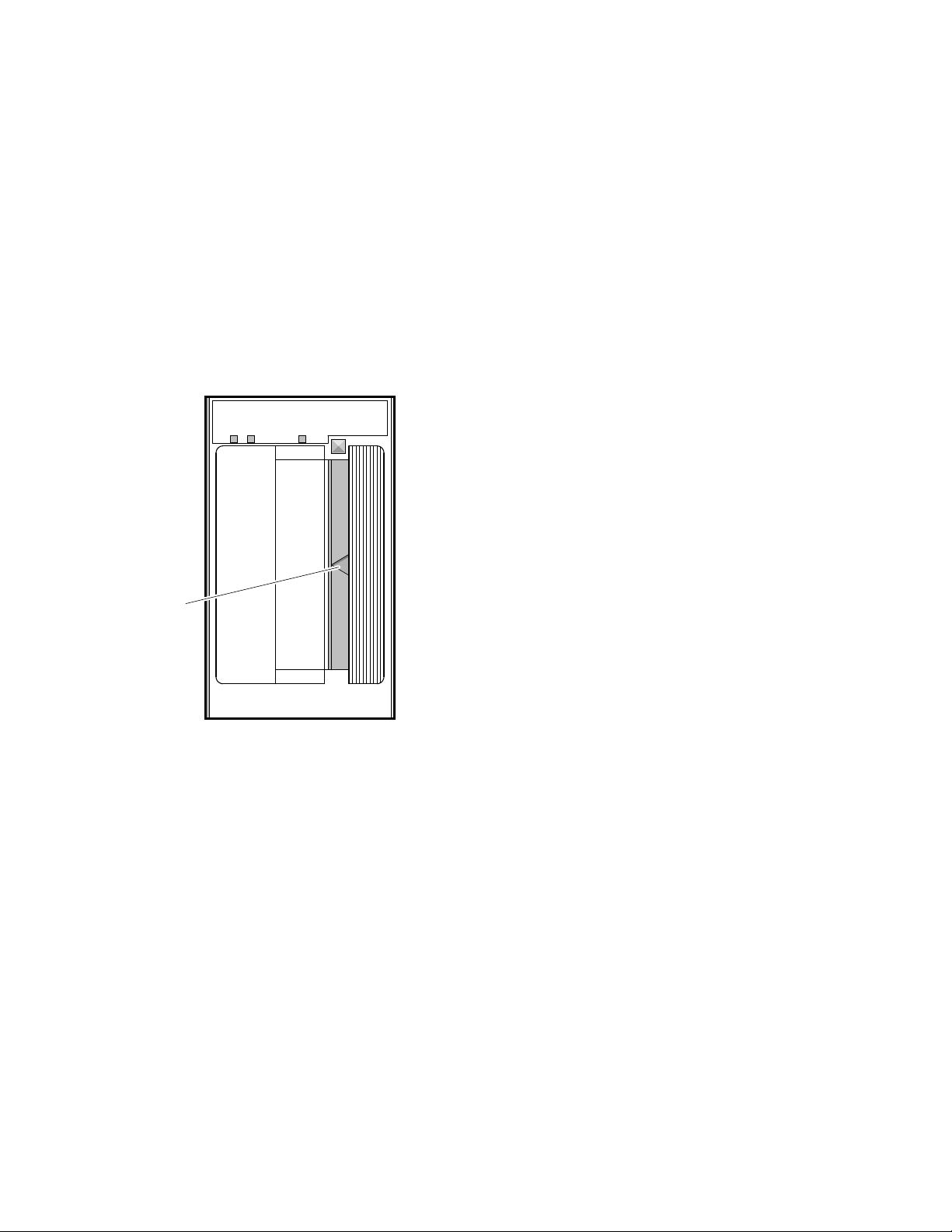
5. Check the settings on the tape drive:
• If a TF-series tape drive is installed in your system:
Make sure the Cartridge Insert/Release handle is closed (pushed in).
Verify that a bus node ID plug is inserted into the drive.
Bus Node
ID Plug
Write
Protected
Use
Tape in Use
Cleaning
Tape
To Load
Handle
Handle
To Unload
Handle
Handle
Operate
Light
Wait
Open this
Insert Tape
Close this
Light
Press Button
Wait
Open this
Remove Tape
Unload
TF85
Cartridge Insert/
Release Handle
MLO-007171
14
• If a TK-series tape drive is installed in your system, make sure the
Cartridge Insert/Release handle is closed (pushed in).
Cartridge
Insert/Release
Handle
MLO-007180
15

7 Connect Additional Devices to the System
You can connect additional devices at this time, or you can complete the
installation (go to Section 8) before connecting the devices.
• If you have devices that must be connected before you start up system
software, connect them now.
CAUTION
To prevent damage to equipment or software, make sure the Power switch
on the power supply panel is off (set at 0).
Make all connections directly to the appropriate system module cover.
16
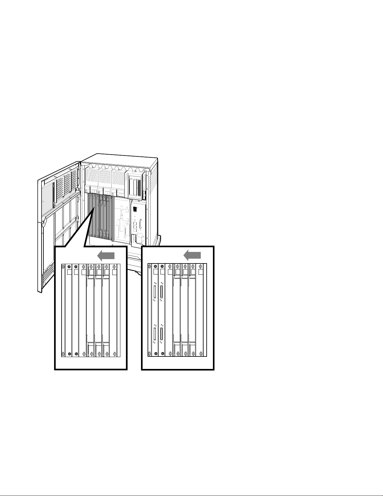
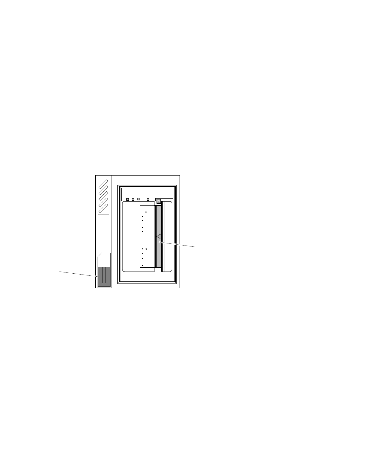
1. Begin with the module at the far right.
-SA
-SA
M3108
M3108
-PA
-PA
-SA
M3108
-PA
J1 J1
J2 J2
-SA
M3108
-PA
6789101112 6789101112
a.
b.
MLO-010175
2. As you complete connections for each module, move left to the next module.
a. If your system has two DSSI ports and looks like ‘‘a’’ in the above
illustration, then slots 6 through 12 are available for Q–bus option
modules.
b. If your system has four DSSI ports and looks like ‘‘b’’ in the above
illustration, then slots 6 through 10 are available for Q–bus option
modules and slots 11 and 12 are DSSI bus bulkheads.
Refer to Section 8 to connect the expander.
17
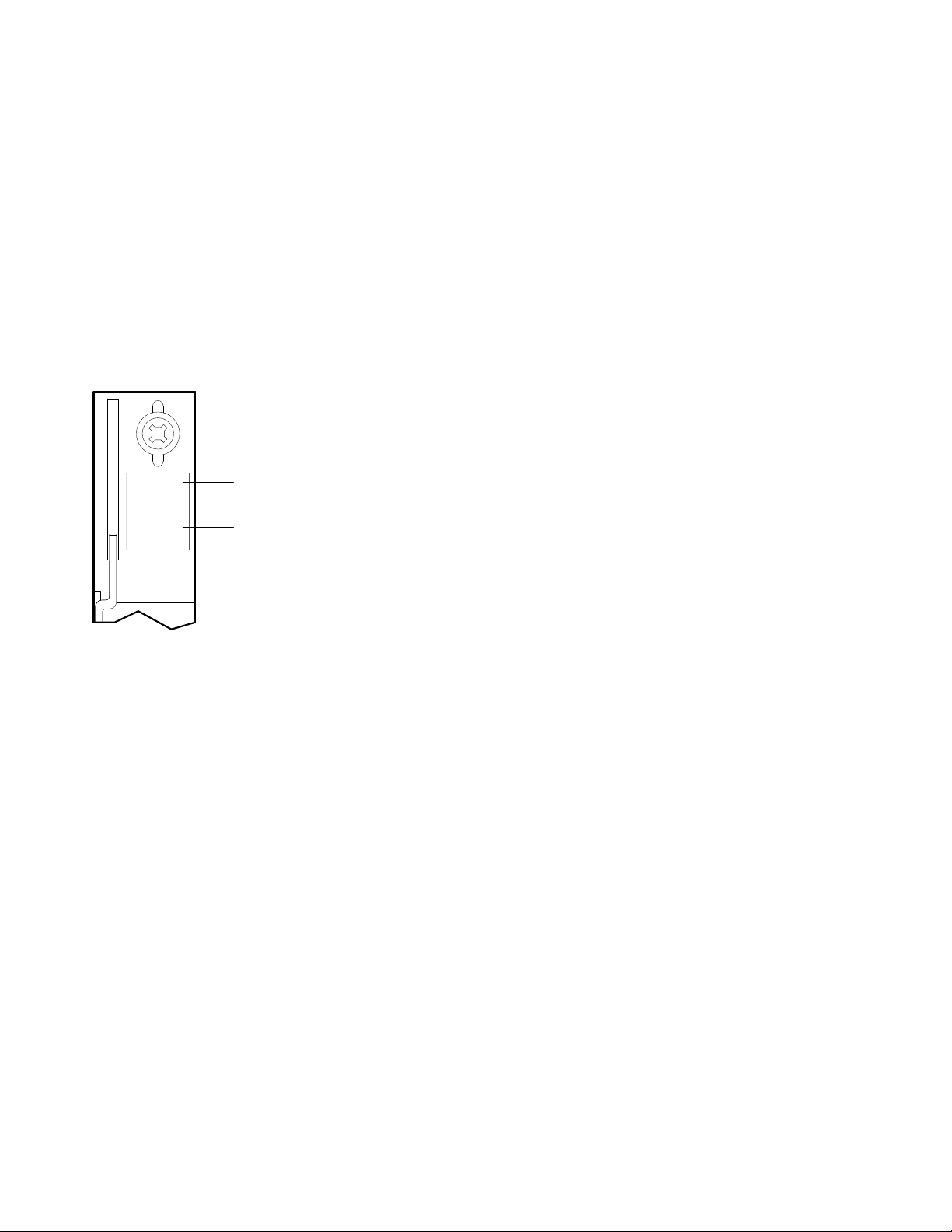
Each module cover has an identifying label at the top, which shows the option
number and module number.
XXXXX
-XX
MXXXX
-XX
Option Number
Module Number
MLO-007118
The following sections tell you how to connect devices to the modules described
in this manual. Connections to other modules are described in the device
installation guides.
Section 7.1 — terminals and serial printers (CXA16 or CXB16 module)
Section 7.2 — parallel printers (LPV11 module)
Section 7.3 — synchronous modems (DSV11 module)
Section 7.4 — asynchronous modems (CXY08 module)
Section 7.5 — Ethernet device (H3604 console module)
Section 7.6 — Ethernet device (DESQA module)
18
 Loading...