

Digital Equipment VAX 4000 Model 300 Installation Manual

VAX 4000 Model 300
Installation
Order Number EK–335AC–IN–003
Digital Equipment Corporation
Maynard, Massachusetts

First Printing, March 1990
Revised, February 1991
Revised, June 1991
The information in this document is subject to change without notice and should not be
construed as a commitment by Digital Equipment Corporation.
Digital Equipment Corporation assumes no responsibility for any errors that may appear in
this document.
The software, if any, described in this document is furnished under a license and may be used
or copied only in accordance with the terms of such license. No responsibility is assumed
for the use or reliability of software or equipment that is not supplied by Digital Equipment
Corporation or its affiliated companies.
Restricted Rights: Use, duplication or disclosure by the U.S. Government is subject to
restrictions as set forth in subparagraph (c)(1)(ii) of the Rights in Technical Data andComputer
Software clause at DFARS 252.227–7013.
© Digital Equipment Corporation 1990, 1991. All rights reserved.
Printed in U.S.A.
The Reader’s Comments form at the end of this document requests your critical evaluation to
assist in preparing future documentation.
The following are trademarks of Digital Equipment Corporation: CompacTape, CX, DDCMP,
DEC, DECconnect, DECdirect, DECnet, DECscan, DECserver, DECUS, DECwindows,
DELNI, DEMPR, DESQA, DESTA, DSRVB, DSSI, IVAX, KDA, KLESI, KRQ50, MicroVAX,
MSCP, Q-bus, Q22-bus, RA, RQDX, RV20, SA, SDI, ThinWire, TK, TMSCP, TQK, TS05, TU,
VAX, VAX 4000, VAXcluster, VAX DOCUMENT, VAXELN, VAXlab, VAXserver, VMS, VT, and
the DIGITAL logo.
FCC NOTICE: The equipment described in this manual generates, uses, and may emit radio
frequency energy. The equipment has been type tested and found to comply with the limits
for a Class A computing device pursuant to Subpart J of Part 15 of FCC Rules, which are
designed to provide reasonable protection against such radio frequency interference when
operated in a commercial environment. Operation of the equipment in a residential area
may cause interference, in which case the user at his own expense may be required to take
measures to correct the interference.
S1653
This document was prepared using VAX DOCUMENT, Version 1.2.

Contents
Preface vii
1 Verify Site Preparation . . . . . . . . . . . . . . . . . . . . . . . . . . . . . 1
2 Check the Shipment . . . . . . . . . . . . . . . . . . . . . . . . . . . . . . . . 1
3 Position the System . . . . . . . . . . . . . . . . . . . . . . . . . . . . . . . . 4
4 Open the System Doors . . . . . . . . . . . . . . . . . . . . . . . . . . . . . 5
5 Install the Console Terminal . . . . . . . . . . . . . . . . . . . . . . . . . 6
5.1 Perform Setup Operations . . . . . . . . . . . . . . . . . . . . . . . . . 7
5.2 Connect the Terminal to the System . . . . . . . . . . . . . . . . . 7
6 Set the System Controls . . . . . . . . . . . . . . . . . . . . . . . . . . . . . 9
7 Connect Additional Devices to the System . . . . . . . . . . . . . . . 13
7.1 Connecting Terminals and Serial Printers . . . . . . . . . . . . . 16
7.2 Connecting Parallel Printers to the System . . . . . . . . . . . . 19
7.3 Connecting Synchronous Modems to the System . . . . . . . . 20
7.4 Connecting Asynchronous Modems to the System . . . . . . . 20
7.5 Connecting an Internal Modem to Telephone Lines . . . . . . 22
7.5.1 DFA01 Modems . . . . . . . . . . . . . . . . . . . . . . . . . . . . . . . 22
7.5.2 RJ11C/CA11A, RJ12C/CA12A, and RJ13C/CA13A
Telephone Service. . . . . . . . . . . . . . . . . . . . . . . . . . . . . . 22
7.5.3 RJ41S/CA41A and RJ45S/CA45A Data-Jack Telephone
Service . . . . . . . . . . . . . . . . . . . . . . . . . . . . . . . . . . . . . . 26
7.5.4 Setting Up Terminal Lines . . . . . . . . . . . . . . . . . . . . . . . 30
7.6 Connecting to an Ethernet Network at the Console Module 31
7.6.1 Making a ThinWire Network Connection at the Console
Module . . . . . . . . . . . . . . . . . . . . . . . . . . . . . . . . . . . . . . 32
7.6.2 Making a Standard Network Connection at the Console
Module . . . . . . . . . . . . . . . . . . . . . . . . . . . . . . . . . . . . . . 35
7.7 Connecting to an Ethernet Network at the DESQA Module 37
7.7.1 Making a ThinWire Network Connection at the DESQA
Module . . . . . . . . . . . . . . . . . . . . . . . . . . . . . . . . . . . . . . 38
7.7.2 Making a Standard Network Connection at the DESQA
Module . . . . . . . . . . . . . . . . . . . . . . . . . . . . . . . . . . . . . . 44
iii

8 Connect an Expander, If Required . . . . . . . . . . . . . . . . . . . . . 45
8.1 Connecting the Q-bus Cables . . . . . . . . . . . . . . . . . . . . . . . 48
8.2 Connecting the DSSI Cable . . . . . . . . . . . . . . . . . . . . . . . . 49
8.3 Connecting the KZQSA External Cable . . . . . . . . . . . . . . . 50
8.4 Connecting the Power Control Bus Cable . . . . . . . . . . . . . 53
8.5 Connecting the Ground Cable . . . . . . . . . . . . . . . . . . . . . . 54
9 Connect the KZQSA Internal Cable, If Required . . . . . . . . . . 54
10 Connect the DSSI Cable — Dual Host Only. . . . . . . . . . . . . . 58
11 Connect the Ground Cable — Dual Host Only . . . . . . . . . . . . 61
12 Connect the System Power Cable . . . . . . . . . . . . . . . . . . . . . . 62
13 Turn On the System and Select a Language . . . . . . . . . . . . . 64
14 Close the System Doors . . . . . . . . . . . . . . . . . . . . . . . . . . . . . 67
15 After Installation . . . . . . . . . . . . . . . . . . . . . . . . . . . . . . . . . . 68
Appendix A Starting and Modifying VMS Factory-Installed
Software
A.1 Pre-Startup Requirements . . . . . . . . . . . . . . . . . . . . . . . . . . . A–1
A.2 Startup Procedure . . . . . . . . . . . . . . . . . . . . . . . . . . . . . . . . . A–2
A.2.1 Modifying FIS for a Standalone System . . . . . . . . . . . . . . . A–3
A.2.2 Modifying FIS for a Simple VAXcluster Network . . . . . . . . A–7
A.2.3 Modifying FIS for a Complex Network or Dual-Host
System . . . . . . . . . . . . . . . . . . . . . . . . . . . . . . . . . . . . . . . . A–11
A.2.3.1 Configuring for Dual-Host Systems . . . . . . . . . . . . . . . . A–12
A.2.3.2 Checking Your Modification Work . . . . . . . . . . . . . . . . . A–12
Index
Figures
1 Shipping Carton Contents . . . . . . . . . . . . . . . . . . . . . . . . . . . 3
2 Sliding the System into Position . . . . . . . . . . . . . . . . . . . . . . 4
3 Lock and Key Positions . . . . . . . . . . . . . . . . . . . . . . . . . . . . . 5
4 Opening the System Doors . . . . . . . . . . . . . . . . . . . . . . . . . . . 6
5 Connecting a VT300-Series or VT400-Series Console Terminal 8
6 System Controls and Indicators — Power Switch . . . . . . . . . 9
iv

7 System Controls and Indicators — Integrated Storage
Element, System Control Panel, and Console Module . . . . . . 11
8 System Controls and Indicators — TK-Series Tape Drives . . 12
9 System Controls and Indicators — TF85 Tape Drive . . . . . . . 13
10 Connecting Devices to a CXA16 or CXB16 Module . . . . . . . . 17
11 Connecting Devices to the Cable Concentrator. . . . . . . . . . . . 18
12 Mounting the Cable Concentrator . . . . . . . . . . . . . . . . . . . . . 19
13 Connecting a Modem to a CXY08 Module . . . . . . . . . . . . . . . 21
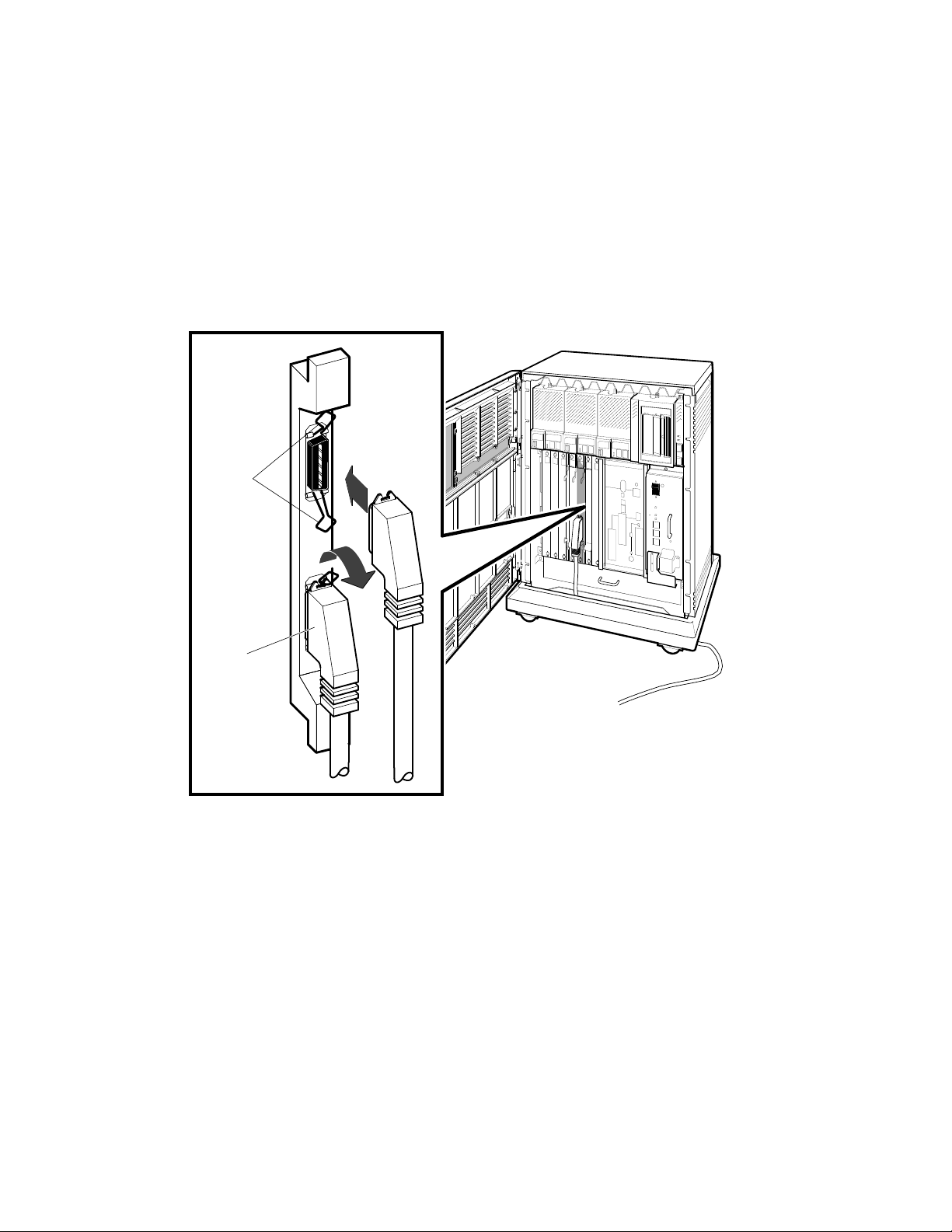
14 Disconnecting the Telephone Line (Single-Line and Multiline
Service) . . . . . . . . . . . . . . . . . . . . . . . . . . . . . . . . . . . . . . . . . 23
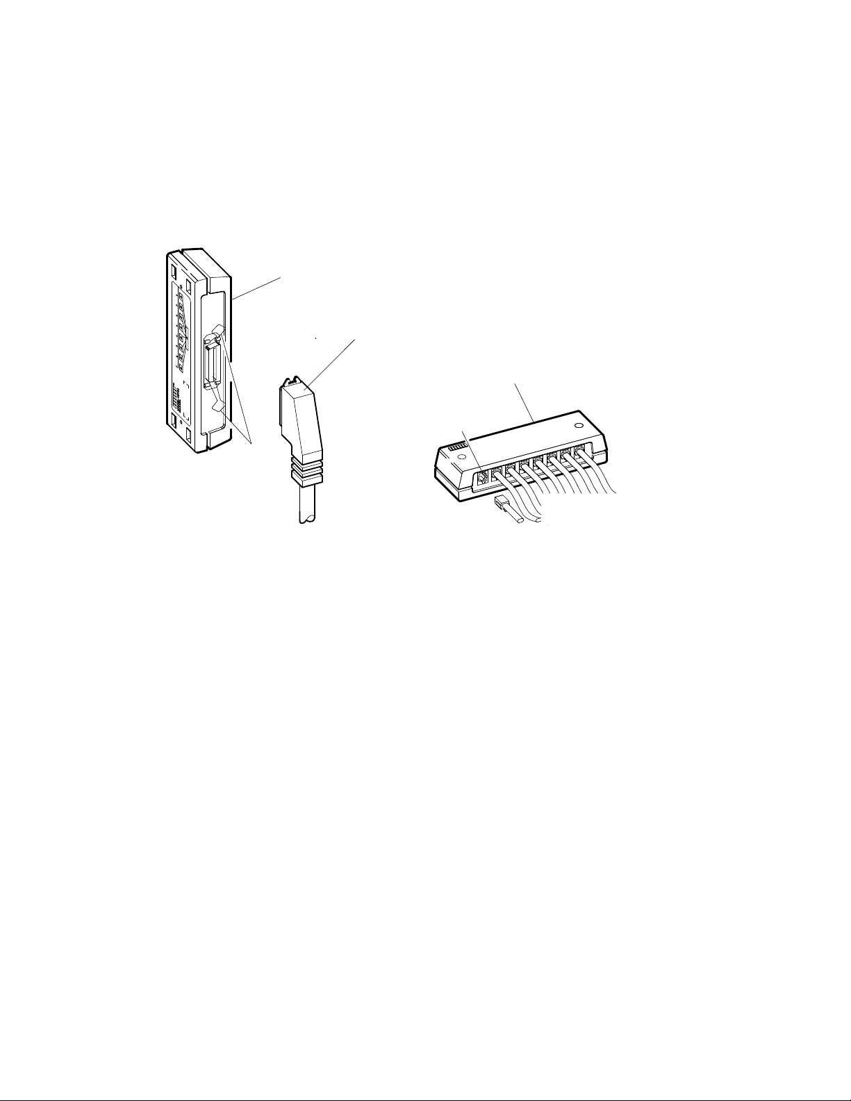
15 Installing the Telephone Cord (Single-Line and Multiline
Service) . . . . . . . . . . . . . . . . . . . . . . . . . . . . . . . . . . . . . . . . . 24
16 Connecting a Modem to a Telephone (Single-Line and
Multiline Service) . . . . . . . . . . . . . . . . . . . . . . . . . . . . . . . . . . 25
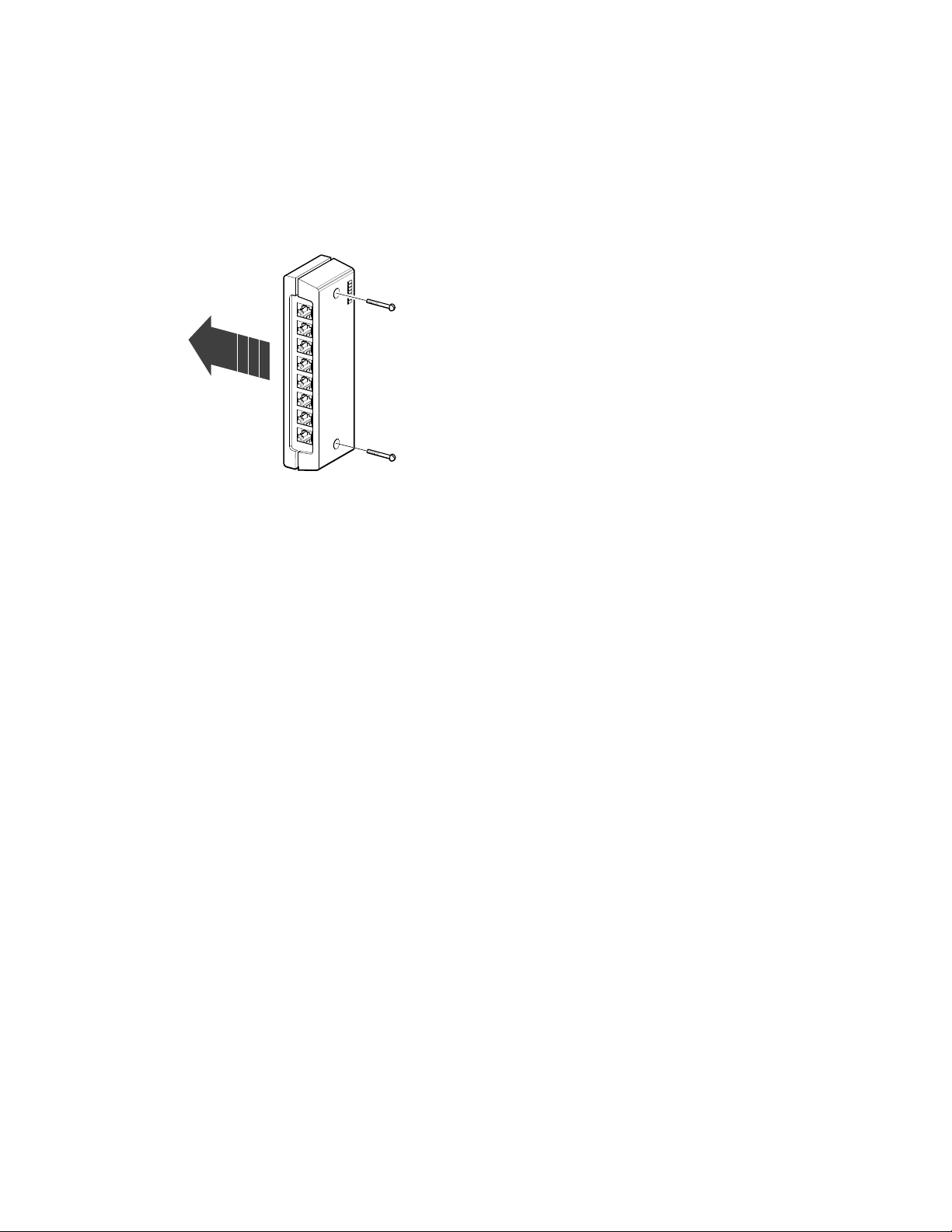
17 Connecting a Modem to a Wall-Mounted Jack (Data-Jack
Service) — Telephone to Wall-Jack Connection . . . . . . . . . . . 27
18 Connecting a Modem to a Wall-Mounted Jack (Data-Jack
Service) — Telephone to DFA01 Connection . . . . . . . . . . . . . . 29
19 Ethernet Connector Switch on the Console Module . . . . . . . . 32
20 ThinWire Cable, T-Connector, and Terminator . . . . . . . . . . . . 33
21 Making a ThinWire Ethernet Connection at the Console
Module . . . . . . . . . . . . . . . . . . . . . . . . . . . . . . . . . . . . . . . . . . 34
22 Making a Standard Ethernet Connection at the Console
Module . . . . . . . . . . . . . . . . . . . . . . . . . . . . . . . . . . . . . . . . . . 36
23 DESQA ThinWire/Standard Ethernet Connector Switch . . . . 38
24 ThinWire Cable, T-Connector, and Terminator . . . . . . . . . . . . 39
25 Making a ThinWire Ethernet Connection at the DESQA
Module . . . . . . . . . . . . . . . . . . . . . . . . . . . . . . . . . . . . . . . . . . 40
26 Forming the Upper Cable in a Loop at the DESQA Module . . 41
27 Grounding ThinWire Ethernet at the DESQA Module . . . . . . 43
28 Making a Standard Ethernet Connection at the DESQA
Module . . . . . . . . . . . . . . . . . . . . . . . . . . . . . . . . . . . . . . . . . . 44
29 System Connections for Expanders . . . . . . . . . . . . . . . . . . . . 46
30 Connecting the Q-bus Cables . . . . . . . . . . . . . . . . . . . . . . . . . 48
31 Removing the DSSI Terminator . . . . . . . . . . . . . . . . . . . . . . . 49
32 Connecting the DSSI Cable . . . . . . . . . . . . . . . . . . . . . . . . . . 50
33 Removing the KZQSA Terminator . . . . . . . . . . . . . . . . . . . . . 51
34 Connecting the KZQSA External Cable . . . . . . . . . . . . . . . . . 52
v

35 Connecting the Power Control Bus Cable . . . . . . . . . . . . . . . 53
36 Connecting the Ground Cable . . . . . . . . . . . . . . . . . . . . . . . . 54
37 TLZ04/KZQSA System Connection . . . . . . . . . . . . . . . . . . . . . 55
38 TLZ04/KZQSA Module Connection — Removing the
Terminator . . . . . . . . . . . . . . . . . . . . . . . . . . . . . . . . . . . . . . . 56
39 TLZ04/KZQSA Module Connection — Connecting the Cable . 57
40 Removing the DSSI Terminators . . . . . . . . . . . . . . . . . . . . . . 59
41 Connecting the DSSI Cable . . . . . . . . . . . . . . . . . . . . . . . . . . 60
42 Connecting the Ground Cable . . . . . . . . . . . . . . . . . . . . . . . . 61
43 System Power Switch . . . . . . . . . . . . . . . . . . . . . . . . . . . . . . . 62
44 Power Cable Plugs . . . . . . . . . . . . . . . . . . . . . . . . . . . . . . . . . 63
45 Connecting the Power Cable to the System . . . . . . . . . . . . . . 64
46 Language Selection Menu . . . . . . . . . . . . . . . . . . . . . . . . . . . 65
47 Successful System Self-Tests . . . . . . . . . . . . . . . . . . . . . . . . . 66
48 Saving the Language . . . . . . . . . . . . . . . . . . . . . . . . . . . . . . . 67
49 Closing the System Doors . . . . . . . . . . . . . . . . . . . . . . . . . . . 68
Tables
1 Module Identification Labels . . . . . . . . . . . . . . . . . . . . . . . . . 14
vi

Preface
This manual tells you how to install your system, using the following steps.
1. Verify site preparation
2. Check the shipment
3. Position the system
4. Open the system doors
5. Install the console terminal
6. Set the system controls
7. Connect additional devices to the system
8. Connect an expander, if required
9. Connect the KZQSA internal cable, if required
10. Connect the DSSI cable — dual host only
11. Connect the ground cable — dual host only
12. Connect the system power cable
13. Turn on the system and select a language
14. Close the system doors
If you are installing a dual-host system, you must repeat each step for each
host. For more information on dual-host systems, refer to your system
Operation manual and your Dual-Host Systems manual.
A glossary in your Operation manual will help you with word definitions
and abbreviations.
CAUTION: Before installing the system, review your system warranty. The
terms of your agreement with Digital may require that a Digital service
representative install the system. Contact your local Digital representative
if you have any questions.
If you are installing an expander with your system:
1. Use this manual to begin the installation of the system.
vii
2. After you complete step 7, install the expander as described in
the installation document (addendum or manual) shipped with the
expander.
3. Return to this manual (step 8) to complete the installation of the
expander and the system.
NOTE: Some of the devices mentioned in this manual are designed for
multiuser systems and may not be suitable for server systems. If you have a
server system, contact your Digital representative if you have any questions
about whether a device is appropriate for your system.
Conventions
The following conventions are used in this manual.
Convention Meaning
Key
Return
XXXX
NOTE Provides general information about the current topic.
CAUTION Provides information to prevent damage to equipment or software.
WARNING Provides information to prevent personal injury.
A terminal key used in text and examples. For example,
that you press the Break key on your terminal keyboard.
Bold, monospaced type and the symbol for the Return key indicate
interactive input that you must supply. For example,
>>> BOOT MUA0
tells you to enter the command BOOT MUA0 at your console terminal.
Return
Break
indicates
The following warning symbols appear on the power supply. Please review
their meaning.
Indicates a risk of electric shock.
To reduce the risk of injury, do not remove modules, Integrated
Storage Elements (ISEs), or the power supply. No userserviceable parts are inside. Refer servicing questions to
your Digital service representative or to your qualified selfmaintenance personnel.
viii

The equipment is not designed for connection to an IT power
system (a power system without a directly grounded neutral
conductor). The equipment should be plugged into a dedicated
(isolated) ground circuit.
The system contains an automatic voltage-selection power
supply. Voltage selection is not required prior to installation.
ix

1 Verify Site Preparation
You may have received a copy of the system Site Preparation manual, which
describes the physical, environmental, and electrical requirements for your
system. A copy of that manual is also included in your Customer Hardware
Information Kit. If you have not done so, read that manual and follow its
instructions for preparing your site.
• The installation instructions that follow assume your site meets all the
requirements listed in the Site Preparation manual.
• These instructions also assume all terminal data lines, telephone lines,
and network lines that you plan to connect to your system are in place
and clearly labeled.
You will need the following tools to install your system. They are not
included in your shipment.
• Scissors
• Flat-blade screwdriver
• Phillips (cross point) screwdriver
• Adjustable wrench
If you are installing a dual-host system, you must repeat each step in the
installation procedure for each host.
2 Check the Shipment
Before unpacking your system, find the Product Delivery Document. It is
attached to the outside of a carton and is labeled with a blue "i" symbol.
That document lists your order and how it breaks out into the items
shipped.
Your shipment may include several cartons:
• One carton contains the system.
• A smaller carton contains the console terminal, if ordered.
• Another carton contains hardware documentation, software documen-
tation, and software licenses. That carton also contains system software
and diagnostic software if you ordered those items separately.
VAX 4000 Model 300 Installation 1

Depending on your order, your shipment may also include cartons
containing:
• Additional terminal(s)
• Printer(s)
• Modem(s)
• Expander(s)
Make sure your shipment is complete by checking that each item listed as
shipped on the Product Delivery Document appears on a Content Listing
or on a barcode label on the outside of one of the cartons in your shipment.
NOTE: Save all packing materials until you are sure you will not reship
any items in the shipment. And save all items in the shipment until you are
sure you will not use them.
Use the unpacking illustrations on the cartons as a guide to unpack your
shipment, one carton at a time. Check the contents of each carton against
the Content Listing on its side to ensure you received all items.
WARNING: The system weighs 68 kilograms (150 pounds) with all options
installed. Two or more people should move the system.
If any item is missing or damaged:
• Contact your delivery agent.
• Contact your Digital sales representative.
If you ordered a dual-host system, the carton containing the second system
includes the same items as the first carton plus a DSSI cable (BC21M–09).
DSSI stands for Digital Storage Systems Interconnect.
Figure 1 shows the contents of the shipping carton.
2 VAX 4000 Model 300 Installation

Figure 1: Shipping Carton Contents
Anti Static
Anti Static
Keys to Front Door
Installation Checklist
KZQSA
Internal Cable
(BC06P-2F)
Power Cable
Console Terminal Cable
(17-01364-02)
Ground Wire Cable
(12-13756-A8)
DSSI Bus Node ID Plugs
(12-28766-19)
Note:
Unpacking is illustrated on the
exterior of the shipping carton.
TLZ04
Bus Node ID
Plugs
(12-28766-28)
System
MLO-006032
VAX 4000 Model 300 Installation 3

3 Position the System
You can move your system into position in one of two ways as shown in
Figure 2.
• Roll it sideways.
• Slide or walk it backward or forward by gripping the hand holds on the
side of the unit.
WARNING: Do not use the hand holds to lift the system.
Figure 2: Sliding the System into Position
Hand Holds
Slides Front
to Back
Rolls Left to Right
MLO-004012
Leave space behind the system for routing cables. Once installation is
complete, you can place the system directly against a wall. Its oversized
base ensures enough space for proper rear ventilation.
4 VAX 4000 Model 300 Installation
4 Open the System Doors
The system doors are locked. To unlock and open them:
1. Find the key in the shipping carton (Figure 1). Two keys are provided,
one to keep as a spare.
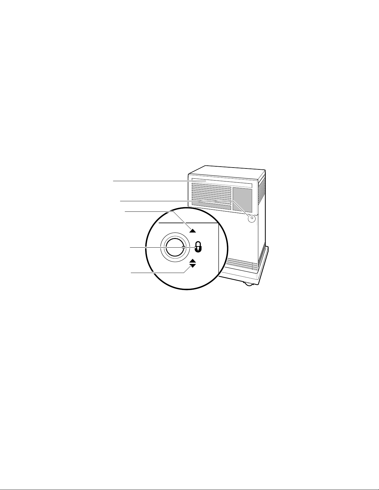
2. Insert the key in the three-position rotary lock shown in Figure 3. Turn
the key to the bottom position to open the upper and lower doors as a
single unit.
3. Open the doors by pulling the handle on the upper door. Figure 3 shows
the door handle.
Figure 3: Lock and Key Positions
Door Handle
Rotary Key Lock
Top Key Position:
Access to SCP, ISEs, and
Tape Drive Controls and
Indicators (Upper Door Open)
Middle Key Position:
No Access to Controls
(Both Doors Locked)
Bottom Key Position:
Access to Power Switch;
All Controls and Indicators
(Both Doors Open)
MLO-006033
SCP stands for system control panel and ISE stands for Integrated
Storage Element.
VAX 4000 Model 300 Installation 5
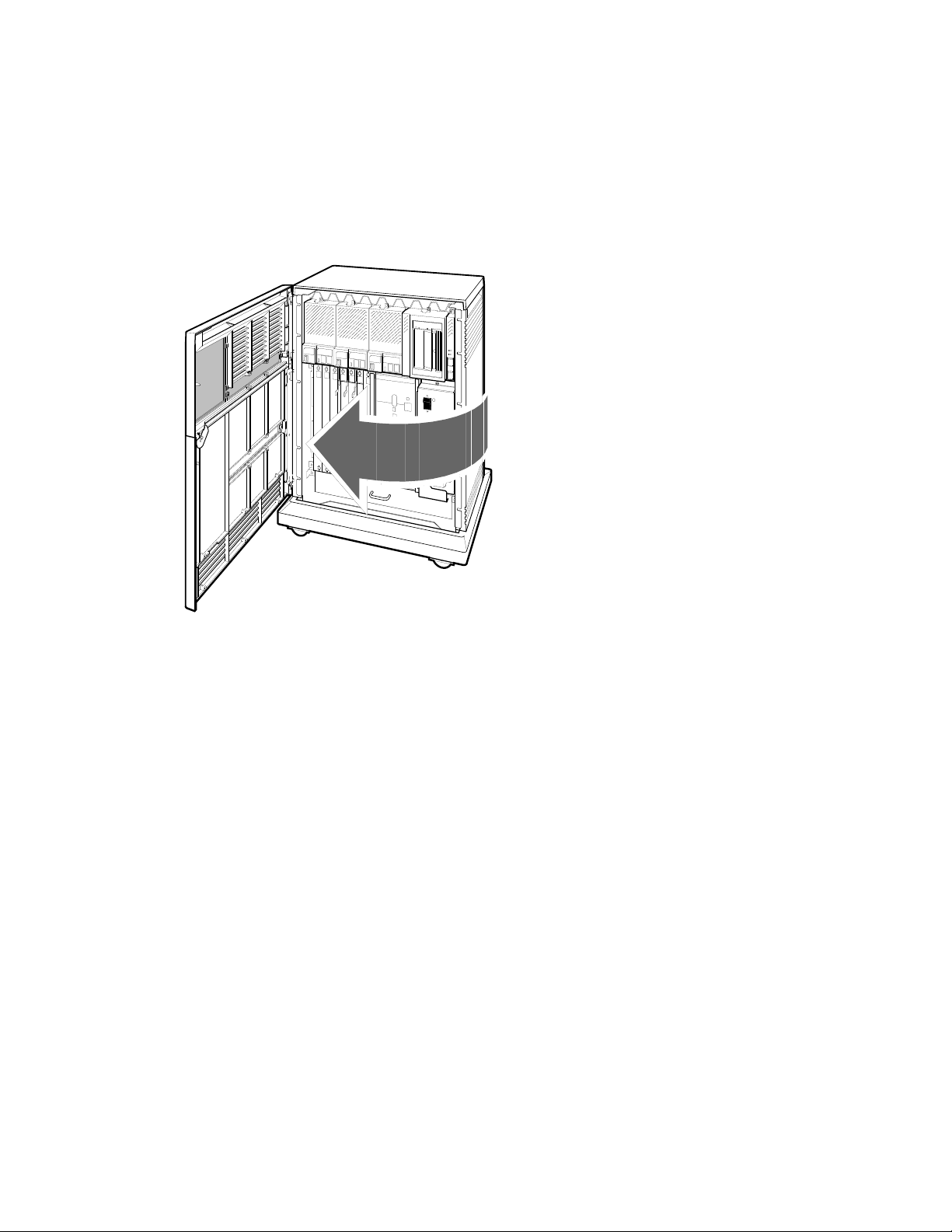
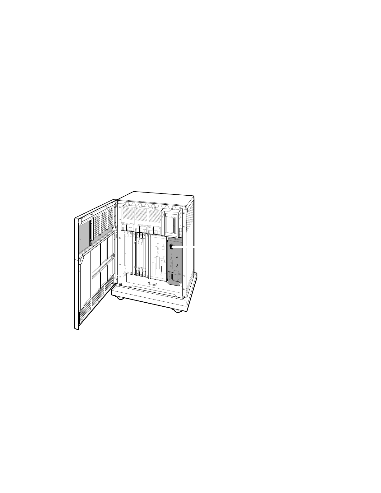
4. Swing the doors open. Figure 4 shows the system with the upper and
lower doors open.
Figure 4: Opening the System Doors
MLO-004013
Now you are ready to install the console terminal.
5 Install the Console Terminal
You will use the console terminal to communicate with your system.
1. Unpack the terminal and its documentation.
2. Use the instructions in the terminal installation guide to connect the
various parts of the terminal.
3. Turn on the terminal.
The terminal performs a self-test. The documentation for the terminal
describes a successful self-test and error messages you receive if the
terminal is not operating properly.
6 VAX 4000 Model 300 Installation

Once the terminal passes its self-test, you are ready to perform setup
operations.
5.1 Perform Setup Operations
Setup instructions for terminals vary according to model or according to
which read-only memory (ROM) is installed in the terminal. Be sure to:
• Read the documentation provided with your terminal.
• Follow the setup instructions for your terminal.
NOTE: A new terminal from Digital has the baud rate set to 9600. If your
terminal is new and you want to use that rate, you can skip the baud rate
setup instructions.
If you have a dual-host system, you can use one terminal with dual sessions
instead of two terminals. See your terminal documentation for instructions.
Once you test the terminal and perform setup operations, you are ready to
connect the terminal to your system.
5.2 Connect the Terminal to the System
You will attach one end of a cable to the console module and the other end
of the cable to a communication port in the back of the terminal.
• The console module is on the front of the system and covers backplane
slots 1 through 5.
• The port on the back of the terminal varies with the type of terminal.
Refer to the instructions that follow to connect a VT300-series or VT400series terminal to a 120-volt or 240-volt system.
1. Turn off the terminal.
2. Find the console terminal cable. It is labeled 17–01364–02 and has a
DEC–423 modular plug on each end.
3. Connect the terminal cable to the DEC–423 modular jack labeled 1 on
the rear of the terminal, according to the instructions in your terminal
installation guide.
VAX 4000 Model 300 Installation 7
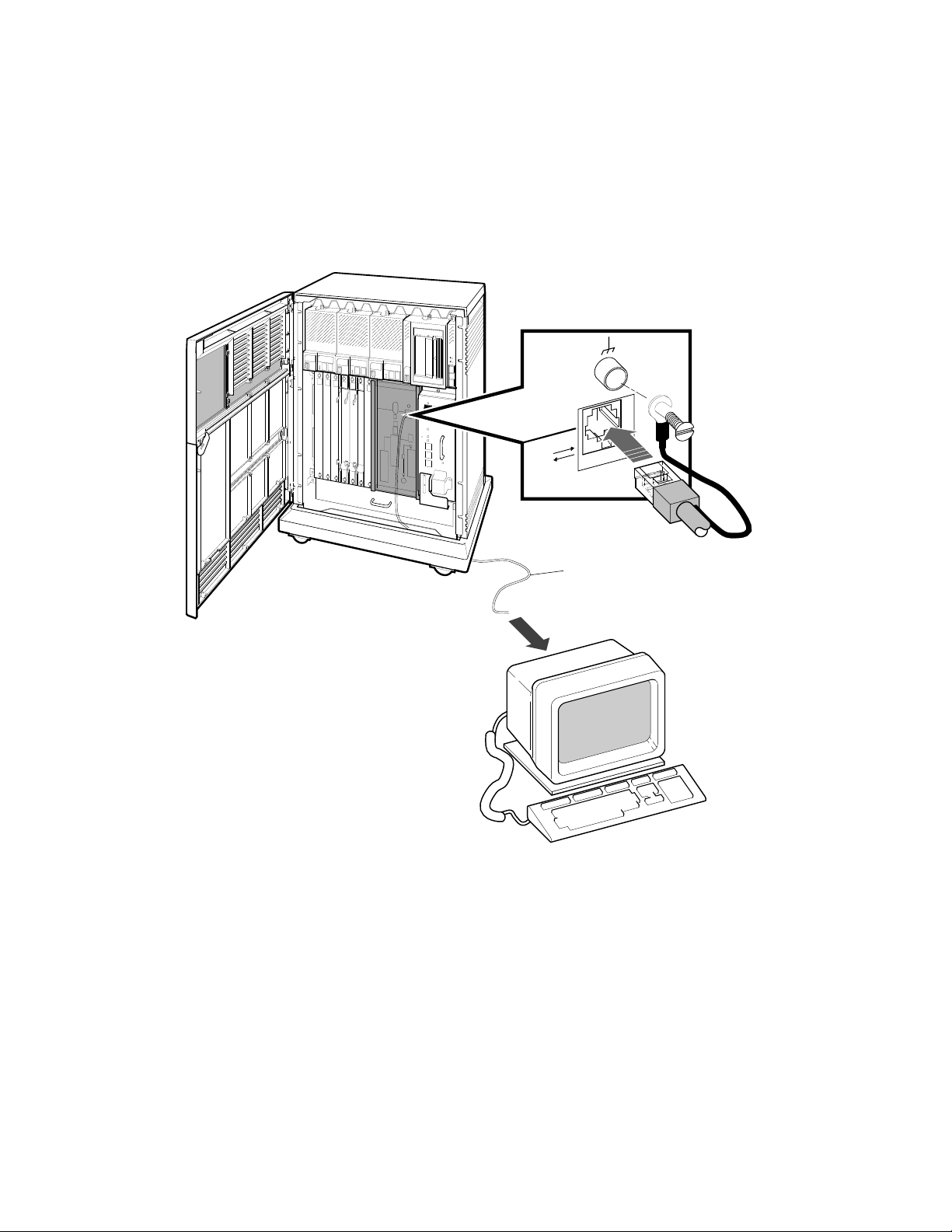
4. Feed the other end of the cable under the system from the back or side.
Then draw up the cable and insert it into the DEC–423 modular jack
shown in Figure 5.
Figure 5: Connecting a VT300-Series or VT400-Series Console Terminal
Terminal
Cable
8 VAX 4000 Model 300 Installation
MLO-004014
5. Connect the ground lead as shown in Figure 5.
a. Loosen the ground screw, above the modular jack.
b. Slide the end of the lead under the screw.
c. Tighten the screw.
You are now ready to set the controls on your system.
6 Set the System Controls
The system controls are on the power supply, Integrated Storage Elements,
system control panel, console module, and tape drives.
1. Check the setting of the Power switch on the power supply shown in
Figure 6. It should be off (set at 0).
Figure 6: System Controls and Indicators — Power Switch
Power Switch
MLO-004263
VAX 4000 Model 300 Installation 9

2. Check the settings on each RF-series Integrated Storage Element (ISE).
One is shown in Figure 7.
• Write-Protect button — Make sure that button is in the out (write-
enabled) position.
• Run/Ready button — Make sure that button is in the in (ready)
position.
Verify that a bus node ID plug is inserted into each ISE.
3. Check the setting of the Halt button on the system control panel shown
in Figure 7. It should be in the out (run) position.
4. Check the settings on the console module shown in Figure 7.
• Power-Up Mode switch — Set that switch to the Language Inquiry
mode (uppermost position, indicated by a human profile).
• Baud Rate Select switch — You should have set the console terminal
baud rate to your preference. Set the system to the same rate.
• Break Enable/Disable switch — Set that switch to break enabled
(up, indicated by a 1).
10 VAX 4000 Model 300 Installation
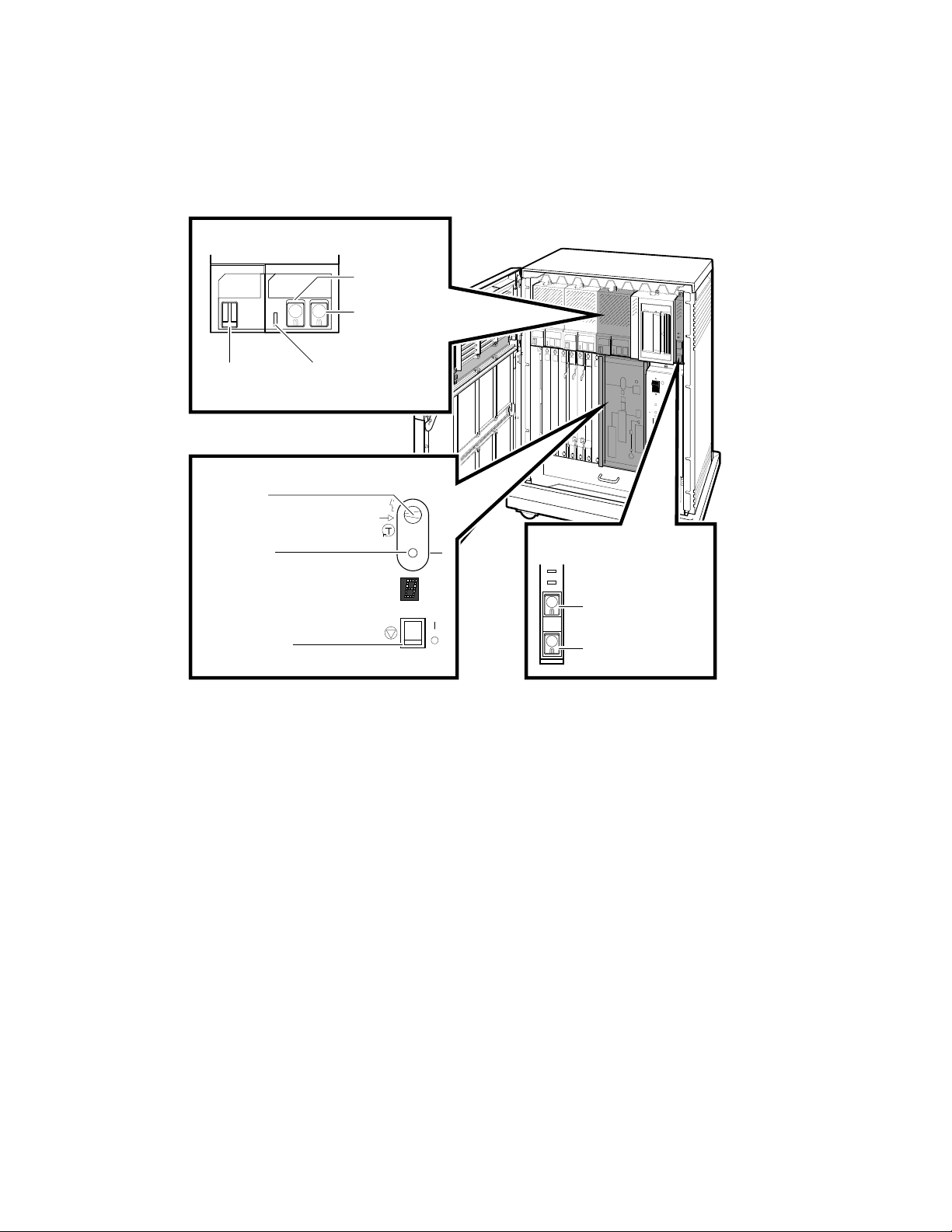
Figure 7: System Controlsand Indicators —Integrated Storage Element,
System Control Panel, and Console Module
ISE Controls and Indicators
Run/Ready
Button
Write-Protect
Button
Bus Node
Fault Indicator
ID Plug
Console Module
Power-Up
Mode Switch
Baud Rate
Select Switch
Break Enable/
Disable Switch
Baud
300___________0
600___________1
1200__________2
2400__________3
4800__________4
9600__________5
19200_________6
38400_________7
5
System Control Panel
Halt Button
Restart Button
MLO-006034
VAX 4000 Model 300 Installation 11
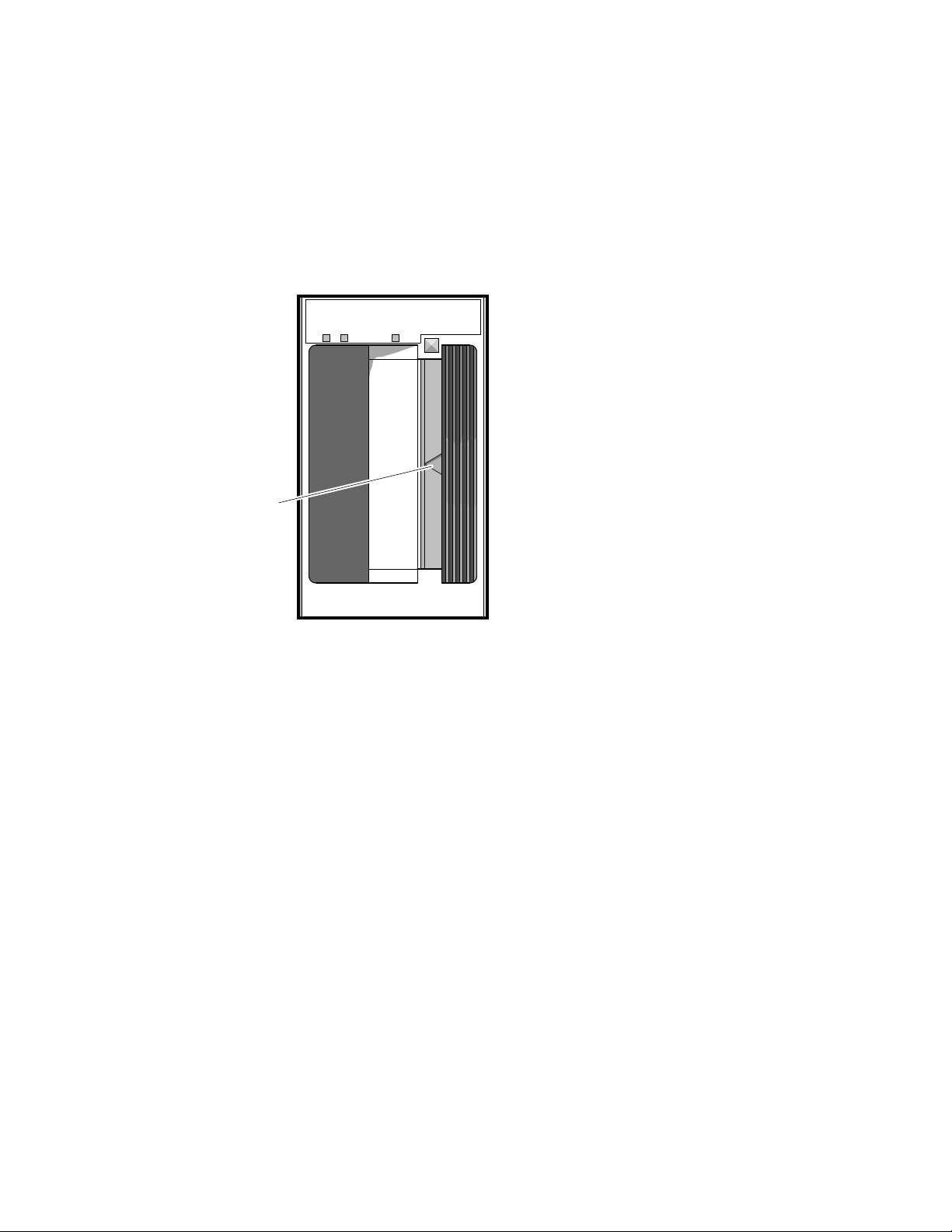
5. Check the settings on the tape drive.
• If a TK-series tape drive is installed in your system, check the
setting of the Cartridge Insert/Release handle shown in Figure 8.
Make sure that handle is closed (pushed in).
Figure 8: System Controls and Indicators — TK-Series Tape Drives
Cartridge
Insert/Release
Handle
MLO-006525
• If a TF85 tape drive (Figure 9) is installed in your system:
Make sure the Cartridge Insert/Release handle is closed
(pushed in).
Verify that a bus node ID plug is inserted into the drive.
12 VAX 4000 Model 300 Installation
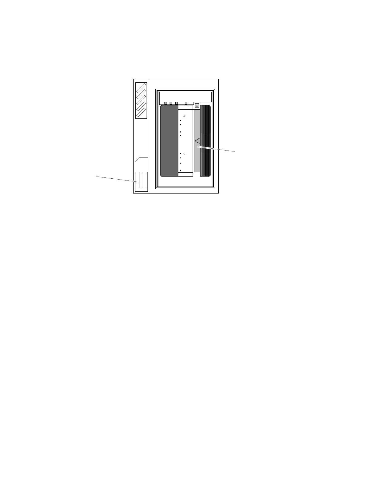
Figure 9: System Controls and Indicators — TF85 Tape Drive
Use
Tape in Use
Cleaning
Tape
To Load
Handle
Handle
To Unload
Handle
Handle
Operate
Light
Wait
Open this
Insert Tape
Close this
Light
Press Button
Wait
Open this
Remove Tape
Unload
TF85
Cartridge Insert/
Release Handle
Write
Protected
Bus Node
ID Plug
MLO-006604
• You do not have to set controls on the TLZ04 tape drive for system
installation.
You are now ready to connect additional devices to your system.
7 Connect Additional Devices to the System
You can connect additional devices at this time, or you can complete the
installation (skip to step 8) before connecting additional devices.
• If you have devices that must be installed before you start up system
software, install them now.
• Otherwise, skip to step 8 if you prefer to connect additional devices
later.
Use the following instructions when you are ready to connect the devices.
CAUTION: Make sure the Power switch on the power supply panel is off (set
at 0).
Make all connections directly to the appropriate module cover.
1. Begin with the module at the far right.
VAX 4000 Model 300 Installation 13

2. As you complete connections for each module, move left to the next
module.
The following numbered sections tell you how to connect each type of device.
To help you make the proper connections, each module cover has an
identifying label at the top. That label contains the module number and
option number. Table 1 lists the identifying labels for all modules you can
use on your system. Use the table to identify the modules as you connect
additional devices to your system. (Not all modules require additional
connections.)
Table 1: Module Identification Labels
Module
Number
CPU and Memory
L4000–AA KA670–AA System CPU (multiuser)
L4000–BA KA670–BA System CPU (server)
L4001–BA MS670–BA System memory, 32 megabytes
L4001–CA MS670–CA System memory, 64 megabytes
M8578–00 MRV11 Programmable read-only memory
Mass Storage
M5976–SA KZQSA TLZ04/RRD-series adapter
M7164, M7165 KDA50 Intelligent board controller (RA-series disks and ESE20)
M7206–PA TSV05 TS05 tape drive controller (old)
M7530 TSV05 TS05 tape drive controller (new)
M7546 TQK50 TK50 tape drive controller
M7552–PA KRQ50 RRD-series disc drive controller
M7559 TQK70 TK70 tape drive controller
M7740–PA KLESI RV20 write-once optical disk (or TU81E tape) controller
M7769 KFQSA DSSI mass-storage adapter
Communications
M3108–PA DSV11 2-line synchronous serial interface (full modem support)
M3118–YA CXA16 16-line asynchronous serial interface (RS–423–A, no
Option
Number Description
modem support)
14 VAX 4000 Model 300 Installation

Table 1 (Cont.): Module Identification Labels
Module
Number
Option
Number Description
M3118–YB CXB16 16-line asynchronous serial interface (RS–422, noise
M3119–YA CXY08 8-line asynchronous serial interface (full modem support)
M3121–PA DFA01 2-line asynchronous serial interface with integral modem
M3127–PA DESQA Ethernet adapter
M7531–PA DIV32 ISDN controller, synchronous communication
M7651–PA DRV1W Real-time parallel interface
M8020–PA DPV11 Synchronous serial line interface
M8049–PA DRV1J Real-time parallel interface
Miscellaneous
A026–PA AXV11 D/A and A/D converter
A030–PA ADQ32 32-channel, single-ended, or 16-differential-channel ana-
A1008–PA ADV11 16-channel, single-ended, or 8-differential-channel analog
A1009–PA AAV11 Digital to analog converter
M3125–PA IBQ01 BITBUS to Q-bus DMA controller
M4002–PA KWV11 Programmable real-time clock
M7168, M7169 VCB02 VS30U (QDSS) graphics upgrade
M7533–AB DEQRA DEC TRNcontroller 100 (token ring adapter)
M7658–PA DRQ3B Real-time parallel interface
M8086–PA LPV11 Dual parallel printer interface
M8634–PA IEQ11 IEEE instrument bus DMA controller
M9404, M9405 None BA21X–SF Q-bus expansion kit
immune)
log to digital converter
to digital converter
CAUTION: Do not operate the system without Digital module covers. They
are required to protect the equipment, to maintain proper airflow for cooling,
and to meet international regulatory standards. Do not substitute other
covers as they may not meet the required specifications.
VAX 4000 Model 300 Installation 15

7.1 Connecting Terminals and Serial Printers
You can connect up to 16 terminals and/or serial printers for each CXA16 or
CXB16 module installed in your system. If your site was prepared properly,
the lines for the additional terminals and printers are clearly labeled and
terminate near your system.
• You do not connect the terminals and printers directly to the system,
but to a cable concentrator (H3104) that has connections for up to eight
terminals and printers.
• You then connect the cable concentrator to the system with a BC16D
cable.
For each CXA16 or CXB16 module, two H3104 cable concentrators and two
BC16D cables are shipped with your system.
To connect additional terminals and printers:
1. Find the H3104 cable concentrator and BC16D cable.
2. Feed one end of the BC16D cable under the system from the back or
side and insert it into the connector as shown in Figure 10.
16 VAX 4000 Model 300 Installation
• If you are connecting two BC16D cables, connect the first to the
connector labeled 8–15 on the module cover.
• If you are connecting one BC16D cable, connect that cable to the
connector labeled 0–7.
Lock the connector in place by using the bail latches.
Figure 10: Connecting Devices to a CXA16 or CXB16 Module
Bail
Latches
BC16D
Cable
Feed Cable Under System
and Through Opening
MLO-004017
VAX 4000 Model 300 Installation 17
3. Insert the other end of the BC16D cable into the cable concentrator
shown in Figure 11. Lock the connector in place by using the bail
latches.
Figure 11: Connecting Devices to the Cable Concentrator
H3104 Cable
Concentrator
(Rear View)
BC16D Cable
H3104 Cable
Concentrator
(Front View)
Modified
Modular Jack
Bail
Latches
To Terminals
and Printers
To System
MLO-002274
4. Insert each printer and terminal cable into one of the modified modular
jacks on the cable concentrator as shown in Figure 11.
5. If you have not done so, connect the terminal or printer to the other
end of the cable. Your terminal or printer documentation shows how to
connect the cable.
If the printer or terminal does not have a modified modular jack
connection, use a passive adapter (H8575–A), available in 25-pin and
9-pin models.
Follow the same procedure for connecting a second BC16D cable to the
module, except insert the cable into the connector labeled 0–7.
18 VAX 4000 Model 300 Installation
You can mount the cable concentrator on a wall. Wall mounting keeps
cables off the floor. Use two screws as shown in Figure 12.
Figure 12: Mounting the Cable Concentrator
To Wall
MLO-000651
NOTE: Be sure you mount the cable concentrator less than 7.6 meters (25
feet) from the system, to ensure the BC16D cable reaches the system.
7.2 Connecting Parallel Printers to the System
You can connect up to two parallel printers for each LPV11 module installed
in your system.
To connect parallel printers to the LPV11 module:
1. Find a BC27L–30 cable.
2. Feed one end of that cable under the system from the back or side.
Then insert it into the connector labeled J1 on the module cover. Lock
the connector in place by using the bail latches.
3. Insert the other end of the cable into the printer.
Follow the same procedure for connecting a second printer to the LPV11
module, except insert the cable into the connector labeled J2 on the module
cover.
VAX 4000 Model 300 Installation 19

7.3 Connecting Synchronous Modems to the System
You can connect up to two synchronous modems for each DSV11 module
installed in your system.
To connect a synchronous modem to a DSV11 module, using a protocolspecific adapter and extension cable:
1. Feed the socket end of the 0.6-meter (24-inch) adapter cable (BC19–
B/D/E/F) under the system from the back or side and connect it to
the module. Tighten the two screws on the cable connector using a
screwdriver.
2. Connect the extension cable (BC55D, BC22F or BC19L) to the other end
of the adapter cable. Secure the cables by tightening the two screws at
the connection.
3. Connect the other end of the extension cable to the modem. Refer to
your modem documentation for the location of the connector.
7.4 Connecting Asynchronous Modems to the System
You connect asynchronous modem lines to the CXY08 module which
supports up to eight lines.
To connect a modem to a CXY08 module:
1. Find a BC19N–12 cable.
2. Feed one end of that cable under the system from the back or side and
insert it into the connector as shown in Figure 13.
• If you are connecting two BC19N–12 cables, connect the first to the
connector labeled 4–7 on the module cover.
• If you are connecting one cable, connect it to the connector labeled
0–3.
Lock the connector in place with the bail latches.
20 VAX 4000 Model 300 Installation
 Loading...