

Digital Equipment VAX 4000 Model 100, VAX 4000 Model 100A, VAX 4000 Model 105A Upgrade Instructions
Page 1

VAX4000
Model100/100AUpgrade
toModel105A
Order Number: EK–V411A–CG. A01
May 1994
Digital Equipment Corporation
Maynard, Massachusetts
Page 2

May 1994
Digital Equipment Corporation makes no representations that the use of its products in the
manner described in this publication will not infringe on existing or future patent rights, nor do
the descriptions contained in this publication imply the granting of licenses to make, use, or sell
equipment or software in accordance with the description.
Possession, use, or copying of the software described in this publication is authorized only
pursuant to a valid written license from Digital or an authorized sublicensor.
© Digital Equipment Corporation 1994. All Rights Reserved.
The postpaid Reader’s Comments forms at the end of this document request your critical
evaluation to assist in preparing future documentation.
The following are trademarks of Digital Equipment Corporation: DEC, Digital, ThinWire, VAX,
VAX DOCUMENT, VMS, and the DIGITAL logo.
All other trademarks and registered trademarks are the property of their respective holders.
S2573
This document was prepared using VAX DOCUMENT Version 2.1.
Page 3

Contents
Preface . . . . . . . . . . . . . . . . . . . . . . . . . . . . . . . . . . . . . . . . . . . . . . . . . . . . . vii
1 Overview of the Conversion Process
1.1 In This Chapter . . . . . . . . . . . . . . . . . . . . . . . . . . . . . . . . . . . . . . 1–1
1.2 Overview of the Conversion Processes . . . . . . . . . . . . . . . . . . . . . 1–1
2 Upgrading the VAX 4000 Model 100 System
2.1 In This Chapter . . . . . . . . . . . . . . . . . . . . . . . . . . . . . . . . . . . . . . 2–1
2.2 Procedure Overview . . . . . . . . . . . . . . . . . . . . . . . . . . . . . . . . . . . 2–1
2.3 Unpacking the Kit . . . . . . . . . . . . . . . . . . . . . . . . . . . . . . . . . . . . 2–2
2.4 Upgrading the VMS Operating System . . . . . . . . . . . . . . . . . . . . 2–3
2.5 Replacing the CPU Module . . . . . . . . . . . . . . . . . . . . . . . . . . . . . 2–4
3 Upgrading the VAX 4000 Model 100A System
3.1 In This Chapter . . . . . . . . . . . . . . . . . . . . . . . . . . . . . . . . . . . . . . 3–1
3.2 Procedure Overview . . . . . . . . . . . . . . . . . . . . . . . . . . . . . . . . . . . 3–1
3.3 Unpacking the Kit . . . . . . . . . . . . . . . . . . . . . . . . . . . . . . . . . . . . 3–2
3.4 Before Installing the Kit . . . . . . . . . . . . . . . . . . . . . . . . . . . . . . . 3–3
3.5 Installing the CPU Module . . . . . . . . . . . . . . . . . . . . . . . . . . . . . 3–4
A Mandatory Return Procedure and Forms
A.1 Return Procedure . . . . . . . . . . . . . . . . . . . . . . . . . . . . . . . . . . . . . A–1
A.2 Return Forms . . . . . . . . . . . . . . . . . . . . . . . . . . . . . . . . . . . . . . . . A–2
iii
Page 4

Figures
2–1 Disconnecting the Power Cord . . . . . . . . . . . . . . . . . . . . . . . . 2–4
2–2 Disconnecting the External Cables/Terminators from the Port
Cover . . . . . . . . . . . . . . . . . . . . . . . . . . . . . . . . . . . . . . . . . . . 2–5
2–3 Removing the Enclosure Cover . . . . . . . . . . . . . . . . . . . . . . . 2–6
2–4 Unscrewing the Drive Shelves . . . . . . . . . . . . . . . . . . . . . . . . 2–7
2–5 Disconnecting the Internal Power Cables . . . . . . . . . . . . . . . . 2–9
2–6 Disconnecting Internal DSSI Connectors . . . . . . . . . . . . . . . . 2–10
2–7 Removing a SIMM . . . . . . . . . . . . . . . . . . . . . . . . . . . . . . . . . 2–11
2–8 Disconnecting the Internal SCSI Cable from the CPU
Module . . . . . . . . . . . . . . . . . . . . . . . . . . . . . . . . . . . . . . . . . . 2–12
2–9 Sliding the Drive Mounting Shelves Forward . . . . . . . . . . . . 2–13
2–10 Lifting the Drive Mounting Shelves Upward . . . . . . . . . . . . . 2–14
2–11 Removing the DSSI Daughter Card . . . . . . . . . . . . . . . . . . . . 2–15
2–12 Disconnecting the Q–bus and external SCSI Cables . . . . . . . 2–16
2–13 Removing the Port Cover . . . . . . . . . . . . . . . . . . . . . . . . . . . . 2–17
2–14 Removing Connectors from the Port Cover . . . . . . . . . . . . . . 2–18
2–15 Installing the Alignment Pins on the Port Cover . . . . . . . . . . 2–19
2–16 Installing the Original DSSI Cable on the Port Cover . . . . . . 2–20
2–17 Installing the Q–bus Cable on the Port Cover . . . . . . . . . . . . 2–21
2–18 Installing the Blank Covers on the Port Cover . . . . . . . . . . . 2–22
2–19 Installing the SCSI Cable on the Port Cover . . . . . . . . . . . . . 2–23
2–20 Installing the Port Cover and Cables . . . . . . . . . . . . . . . . . . . 2–24
2–21 Removing the CPU Module . . . . . . . . . . . . . . . . . . . . . . . . . . 2–26
2–22 Installing the DSSI Daughter Card . . . . . . . . . . . . . . . . . . . . 2–28
2–23 Connecting the External SCSI Cable to the CPU Module . . . 2–29
2–24 Connecting the Single DSSI Cable to the Daughter Card . . . 2–30
2–25 Connecting the Q–bus Cable to the CPU Module . . . . . . . . . . 2–31
2–26 Aligning the Drive Mounting Shelves . . . . . . . . . . . . . . . . . . 2–32
2–27 Reinstalling the Drive Mounting Shelves . . . . . . . . . . . . . . . . 2–33
2–28 Securing the Drive Mounting Shelves . . . . . . . . . . . . . . . . . . 2–34
2–29 Installing a SIMM . . . . . . . . . . . . . . . . . . . . . . . . . . . . . . . . . 2–36
2–30 Reconnecting Cables and Terminators . . . . . . . . . . . . . . . . . . 2–37
2–31 Applying the New Medallion . . . . . . . . . . . . . . . . . . . . . . . . . 2–38
3–1 Disconnecting the Power Cord . . . . . . . . . . . . . . . . . . . . . . . . 3–4
3–2 Removing the Enclosure Cover . . . . . . . . . . . . . . . . . . . . . . . 3–5
3–3 Unscrewing the Drive Shelves . . . . . . . . . . . . . . . . . . . . . . . . 3–6
iv
Page 5

3–4 Disconnecting the Internal Power Cables . . . . . . . . . . . . . . . . 3–8
3–5 Disconnecting Internal DSSI Connectors . . . . . . . . . . . . . . . . 3–9
3–6 Removing a SIMM . . . . . . . . . . . . . . . . . . . . . . . . . . . . . . . . . 3–10
3–7 Disconnecting the Internal SCSI Cable from the CPU
Module . . . . . . . . . . . . . . . . . . . . . . . . . . . . . . . . . . . . . . . . . . 3–11
3–8 Sliding the Drive Mounting Shelves Forward . . . . . . . . . . . . 3–12
3–9 Lifting the Drive Mounting Shelves Upward . . . . . . . . . . . . . 3–13
3–10 Removing the DSSI Daughter Card . . . . . . . . . . . . . . . . . . . . 3–14
3–11 Disconnecting the Q–bus and external SCSI Cables . . . . . . . 3–15
3–12 Removing the CPU Module . . . . . . . . . . . . . . . . . . . . . . . . . . 3–17
3–13 Installing the DSSI Daughter Card . . . . . . . . . . . . . . . . . . . . 3–19
3–14 Connecting the External SCSI Cable to the CPU Module . . . 3–20
3–15 Connecting the Single DSSI Cable to the Daughter Card . . . 3–21
3–16 Connecting the Q–bus Cable to the CPU Module . . . . . . . . . . 3–22
3–17 Aligning the Drive Mounting Shelves . . . . . . . . . . . . . . . . . . 3–23
3–18 Reinstalling the Drive Mounting Shelves . . . . . . . . . . . . . . . . 3–24
3–19 Securing the Drive Mounting Shelves . . . . . . . . . . . . . . . . . . 3–25
3–20 Installing a Memory Module . . . . . . . . . . . . . . . . . . . . . . . . . 3–27
3–21 Applying the New Medallion . . . . . . . . . . . . . . . . . . . . . . . . . 3–28
Tables
2–1 Contents of the 53XR–AA Upgrade Kit . . . . . . . . . . . . . . . . . 2–3
3–1 Contents of the 53XR–AA Upgrade Kit . . . . . . . . . . . . . . . . . 3–3
v
Page 6

Page 7

This manual describes how to upgrade a VAX 4000 Model 100 or a VAX 4000
Model 100A system to a VAX 4000 Model 105A by replacing the KA52 CPU
module with a KA53 Module.
Intended Audience
This document is intended for Digital Services personnel and licensed
self-maintenance customers.
Customer Responsibilities
Only qualified maintenance personnel (Digital Services representatives
or qualified self-maintenance customers) should perform the installation
procedure.
If you are not a qualified self-maintenance customer, call Digital Services to
schedule a system conversion. It is your responsibility to perform a software
backup before a Digital Services representative arrives at your site.
When the conversion is complete, return the original CPU module to Digital.
Appendix A contains forms that need to be completed by the Digital Services
representative and signed by both you and the Digital Services representative.
Preface
Digital Services Responsibilities
Before arriving at the site, contact the customer to ensure that the customer’s
software is backed up before arriving at the site.
After installation of the upgrade kit, the you must complete the forms in
Appendix A and remove them from this document. The forms must be signed
by both you and the customer.
vii
Page 8

The following forms are in Appendix A:
• Digital Services Worksheet
• Installation Receipt–Customer Copy
• Installation Receipt–Digital Services Copy
• Returned Material Checklist
You should give the customer the signed Installation Receipt–Customer Copy.
Include the signed Installation Receipt–Digital Services Copy with the CPU
module that is being returned to Digital to ensure that the customer receives
credit.
Organization
This document contains three chapters and one appendix:
• Chapter 1 contains an overview of the upgrade process.
• Chapter 2 provides detailed upgrade conversion procedures for a VAX 4000
Model 100.
• Chapter 3 provides detailed upgrade conversion procedures for a VAX 4000
Model 100A.
• Appendix A contains forms for the return of the original CPU module.
Conventions
The following conventions are used in this guide:
Convention Description
x A lowercase italic x indicates the generic use of a letter. For
italic type Italic type emphasizes important information or indicates
Note A note contains information that is of special importance to the
Caution A caution contains information to prevent damage to the
viii
example, xxx indicates any combination of three alphabetic
characters.
variables. It is also used for the titles of manuals.
user.
equipment.
Page 9

Related Documents
The following list contains related documents:
Documentation Order Number
VAX 4000 Model 105A Installation Information EK–512AA–IN
VAX 4000 Model 105A Operator Information EK–513AA–OP
VAX 4000 Model 105A Customer Technical Information EK–514AA–TI
VAX 4000 Model 105A Troubleshooting and Diagnostics
Information
EK–515AA–TS
ix
Page 10

Page 11

Overview of the Conversion Process
1.1 In This Chapter
This chapter describes the general process for upgrading a VAX 4000
Model 100 or Model 100A to a VAX 4000 Model 105A system by replacing
the KA52 CPU module with a KA53 CPU module.
1.2 Overview of the Conversion Processes
Tasks required to upgrade VAX 4000 models are summarized below. To begin
the actual conversion, turn to Chapter 2 for the conversion of a VAX 4000
Model 100, or Chapter 3 for the conversion of a VAX 4000 Model 100A.
The VAX 4000 Model 100A is identical to the VAX 4000 Model 100, except that
the port cover is designed to accomodate a dual DSSI port.
The conversion of a VAX 4000 Model 100A to Model 105A involves replacing
the CPU module and the system medallion. These procedures are described in
detail in Chapter 3.
The conversion of a VAX 4000 Model 100 to Model 105A includes upgrading
with a new port cover (as if it were being converted first to a Model 100A),
then replacing the CPU module and the system medallion. These procedures
are described in detail in Chapter 2.
1
Overview of the Conversion Process 1–1
Page 12

Page 13

Upgrading the VAX 4000 Model 100
2.1 In This Chapter
This chapter lists detailed step-by-step procedures for upgrading a VAX 4000
Model 100 system to a Model 105A.
2.2 Procedure Overview
The conversion procedure is summarized next. To begin the actual conversion,
turn to Section 2.3.
1. Have the customer back up the system software.
2. Unpack and verify the conversion kit.
3. Upgrade the VMS disk 5.5-2H4 (VMS 6.1 is acceptible).
4. Shut down the operating system.
5. Turn off the system power and remove the power cord.
2
System
6. Disconnect all external cables.
7. Remove the enclosure cover.
8. Remove the memory SIMMs (memory modules).
9. Remove the upper and lower drive mounting shelves.
10. Disconnect and remove the DSSI daughter card.
11. Disconnect all internal cables from the port cover to the CPU module,
daughter cards and the drives.
12. Remove the present port cover with attached cables.
13. Remove all attached cables from the present port cover for use on the new
one.
Upgrading the VAX 4000 Model 100 System 2–1
Page 14

Upgrading the VAX 4000 Model 100 System
2.2 Procedure Overview
14. Install the alignment pins with washers on the new port cover.
15. Install the internal cables on the new port cover.
16. Install the new port cover with its connectors onto the rear of the system
box, feeding the cables through the cutouts in the system box.
17. Remove the CPU module.
18. Install the new CPU module.
19. Connect all cables to the CPU module and daughter cards.
20. Reinstall the upper and lower drive mounting shelves in the system box,
and connect the internal SCSI cable to the CPU module.
21. Reinstall the SIMMs.
22. Reinstall the enclosure cover.
23. Connect the power cable, signal cables, and terminators to the system as
desired.
24. Remove the system medallion and install the new one.
25. Have the customer reinstall system data (if necessary).
26. Fill out the forms in Appendix A.
27. Return the original CPU module as instructed (see Appendix A).
2.3 Unpacking the Kit
Unpack the kit as follows:
1. Make sure there is no external damage to the shipping container, such as
dents, holes, or crushed corners.
2. Unpack the conversion kit and check its contents against the shipping
invoice. Table 2–1 lists the kit contents for the Model 100/100A to Model
105A upgrade, 53XR–AA. Other items may be present, but are not required
for this conversion.
2–2 Upgrading the VAX 4000 Model 100 System
Page 15

Upgrading the VAX 4000 Model 100 System
2.3 Unpacking the Kit
CAUTION
Static discharge can damage modules. Use an antistatic wrist strap
and antistatic mat during handling. The wrist strap and mat are in
the antistatic kit in the Digital Services toolkit.
3. Unpack the KA53 CPU module and place it on a grounded antistatic mat.
4. Save the packing material, and use it to return the original CPU module.
5. If any item is missing or damaged:
• Contact the customer’s sales representative.
• Contact the customer’s delivery agent.
Table 2–1 Contents of the 53XR–AA Upgrade Kit
Description Part Number Quantity
Wire harness assy 17–03615–001 1
Product conversion label 36–15946–00 1
Regulatory label 36–30382–23(24) 1
NVAX CPU 54–21797–02 1
Medallion 74–37642–32 1
DSSI blank panel 74–46956–01 2
Expansion port cover 74–46957–01 1
Machine screw, 8mm 90–10917–01 4
VAX 4000 Model 100/100A
Upgrade to Model 105A
VMS multimedia Viking QA–001AA–UW 1
Model 105A doc set QZ–K04AB–GZ 1
EK–V411A–CG 1
2.4 Upgrading the VMS Operating System
If you do not have VMS operating system version 6.1 on your system, it is
necessary to upgrade it before installing the hardware by following these steps:
1. Have the customer back up the system software before the Digital Services
representative arrives. It is the customer’s responsibility to back up the
system software.
2. Power up the system and run diagnostics to verify system operation.
Upgrading the VAX 4000 Model 100 System 2–3
Page 16
Upgrading the VAX 4000 Model 100 System
2.4 Upgrading the VMS Operating System
3. Upgrade the VMS disk 5.5-2H4.
4. Shut down the operating system in the proper manner.
5. Turn off the system power before installing the kit.
2.5 Replacing the CPU Module
To replace the CPU module:
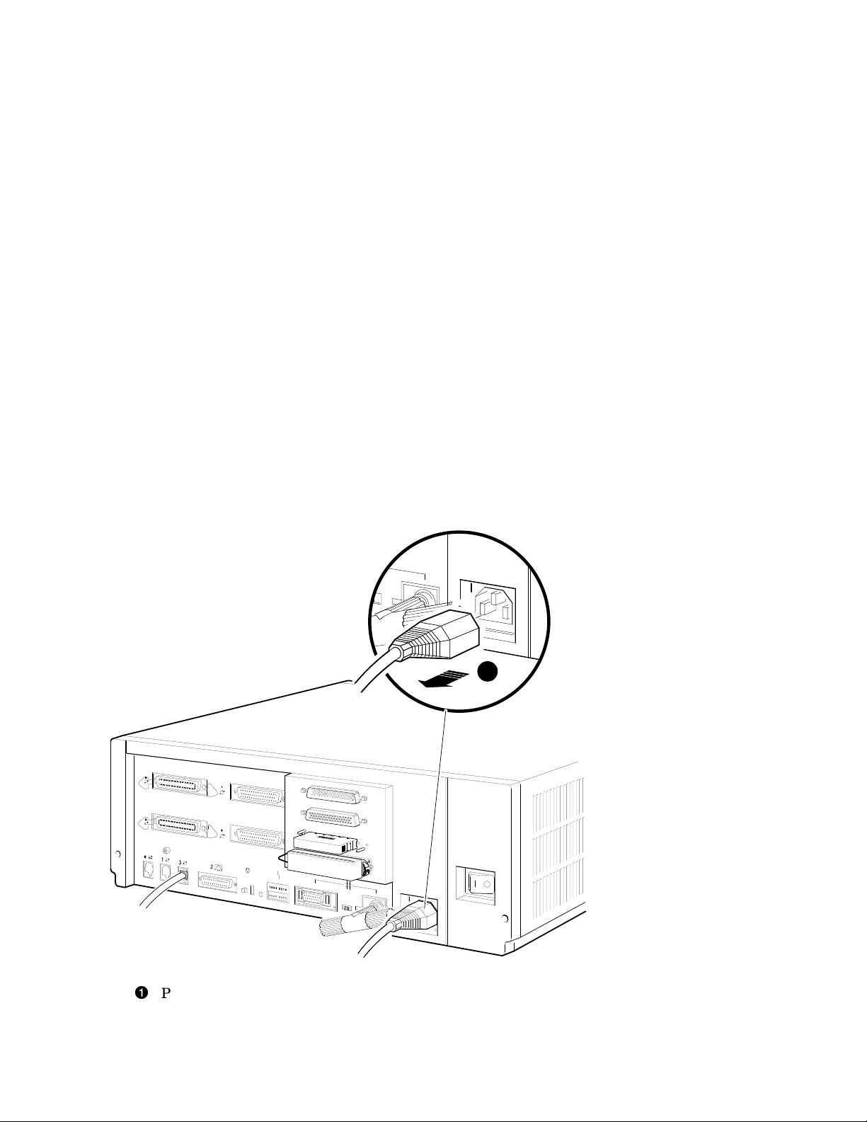
1. Disconnect the power cord from the wall outlet, then from the system (see
Figure 2–1).
Figure 2–1 Disconnecting the Power Cord
1
Power cord
2–4 Upgrading the VAX 4000 Model 100 System
MLO-010799
Page 17
Upgrading the VAX 4000 Model 100 System
2.5 Replacing the CPU Module
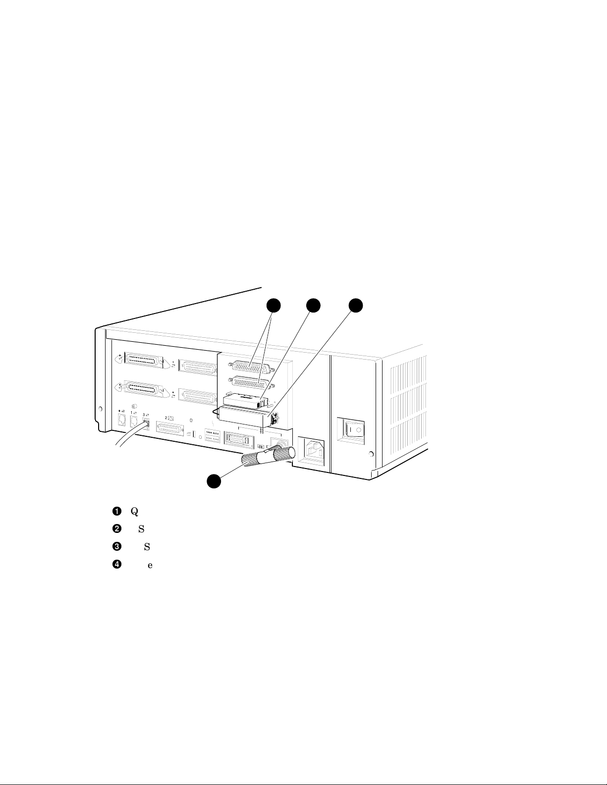
2. Disconnect all the external cables or terminators from the present port
cover, and save the screws (see Figure 2–2).
Figure 2–2 Disconnecting the External Cables/Terminators from the Port
Cover
1 2 3
4
Q–bus ports (Q–bus cables may be attached)
DSSI terminator or cable
SCSI terminator or cable
Ethernet connector
Upgrading the VAX 4000 Model 100 System 2–5
MLO-010800
Page 18
Upgrading the VAX 4000 Model 100 System
2.5 Replacing the CPU Module
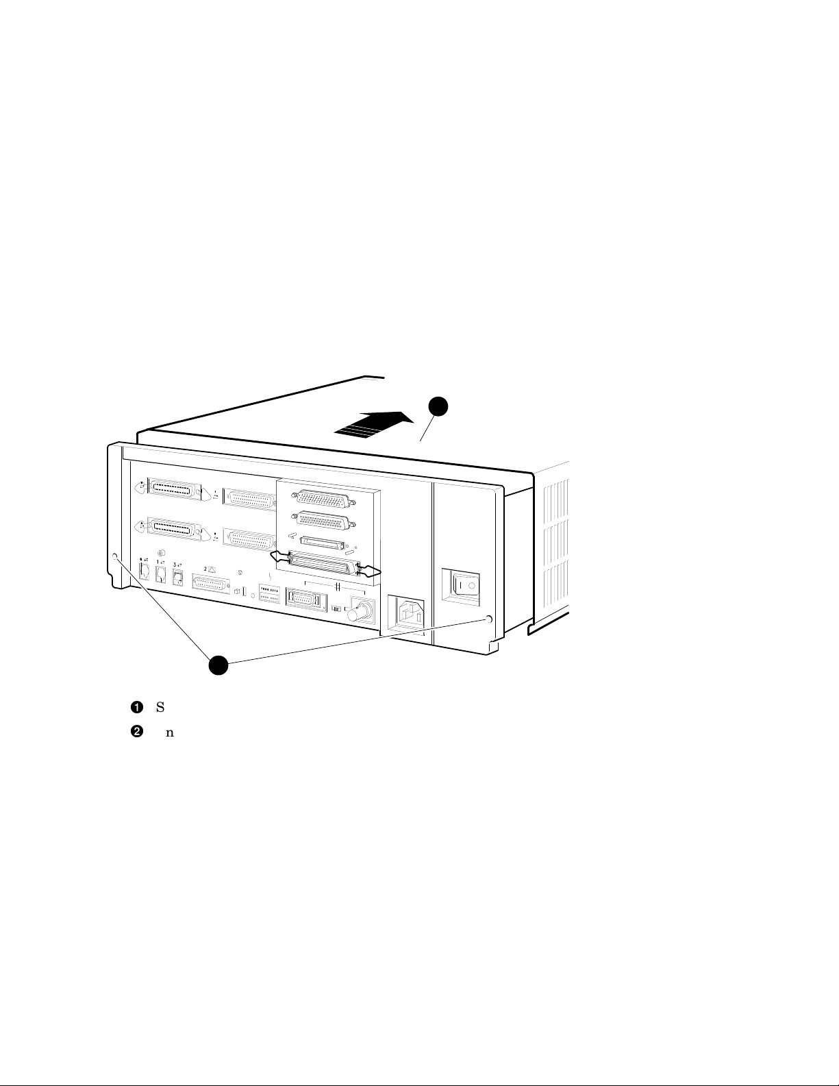
3. Remove the enclosure cover by removing the two screws at the rear of the
system box and sliding it forward (see Figure 2–3).
Figure 2–3 Removing the Enclosure Cover
2
1
Screws
Enclosure cover
2–6 Upgrading the VAX 4000 Model 100 System
MLO-010801
Page 19
Upgrading the VAX 4000 Model 100 System
2.5 Replacing the CPU Module
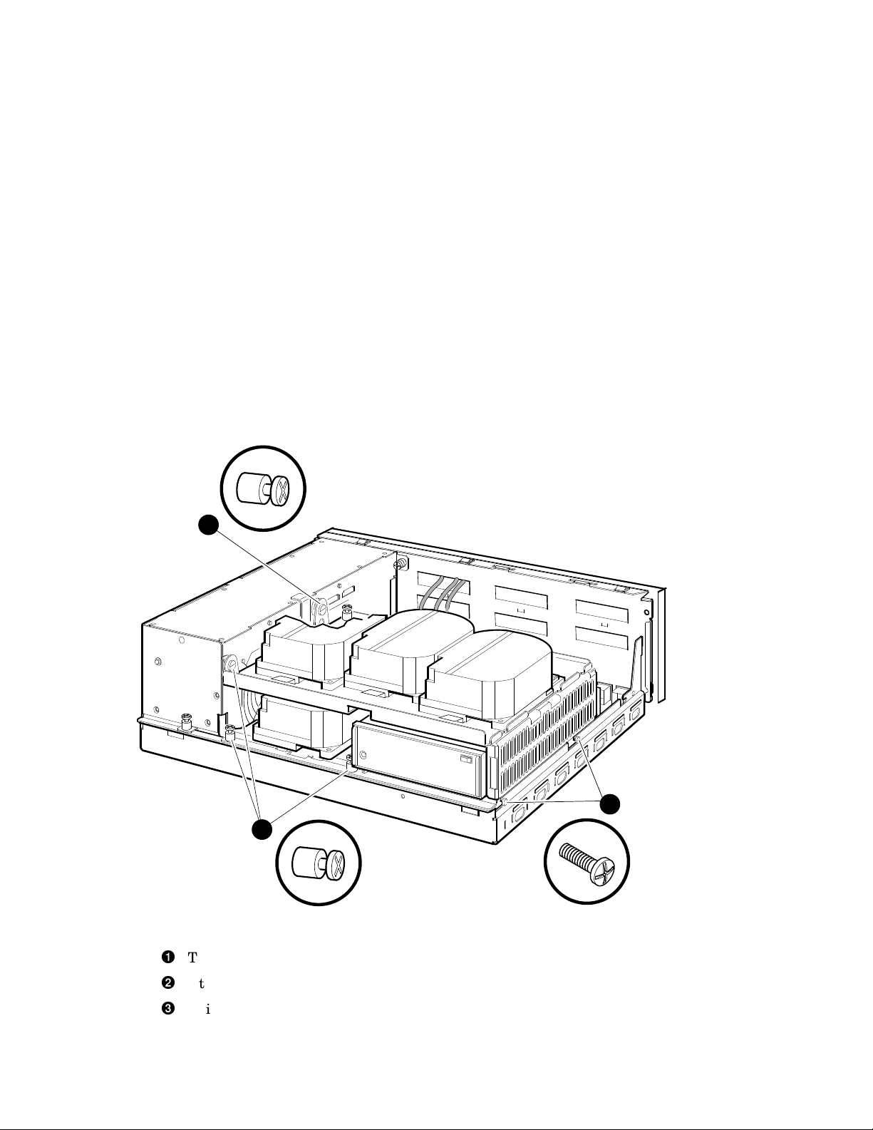
4. Remove the upper and lower drive mounting shelves together as a single
unit (it is not necessary to disassemble the shelves themselves). Unscrew
all six screws from the shelves, leaving the topmost captive screw until
last for support. Leave the captive screws in position and save the Phillips
screws for reinstallation of the shelves (see Figure 2–4).
Figure 2–4 Unscrewing the Drive Shelves
1
2
Topmost captive screw
Other captive screws
Phillips screws
3
MLO-010802
Upgrading the VAX 4000 Model 100 System 2–7
Page 20

Upgrading the VAX 4000 Model 100 System
2.5 Replacing the CPU Module
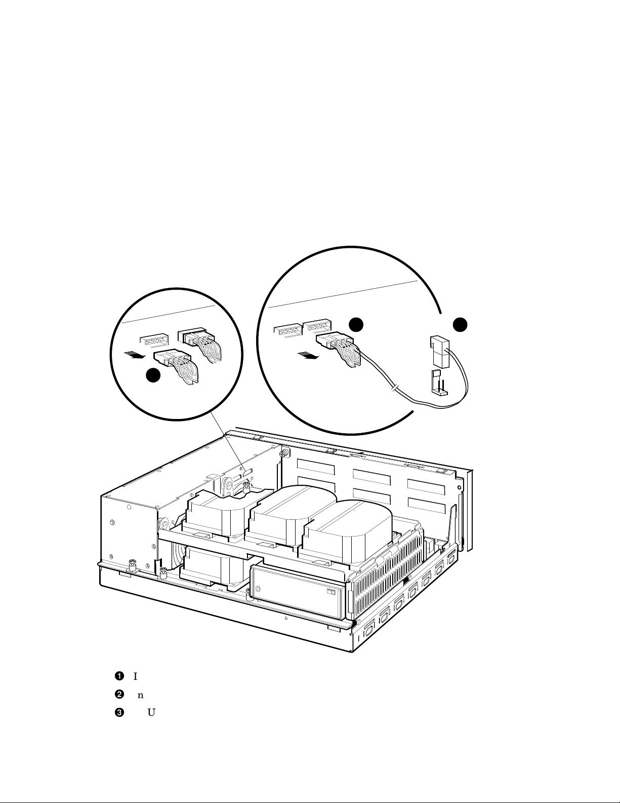
5. Disconnect the internal power cables from the power supply (Figure 2–5).
6. Disconnect the pigtailed, 2-pin DSSI power cable from the CPU module.
(Figure 2–5).
Note
Some VAX 4000 Model 100s do not have the pigtailed power cable, and
you may skip this step in that case.
2–8 Upgrading the VAX 4000 Model 100 System
Page 21
Upgrading the VAX 4000 Model 100 System
2.5 Replacing the CPU Module
Figure 2–5 Disconnecting the Internal Power Cables
1
2 3
Internal power cable
Internal power cable with pigtailed DSSI power cable
CPU module DSSI power cable connector
Upgrading the VAX 4000 Model 100 System 2–9
MLO-012287
Page 22
Upgrading the VAX 4000 Model 100 System
2.5 Replacing the CPU Module
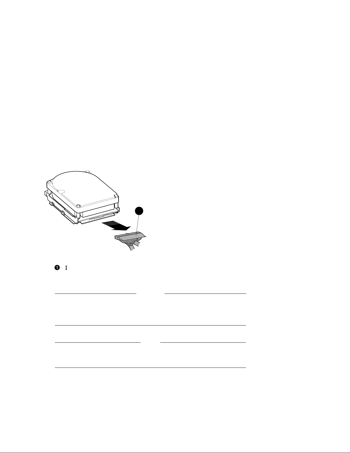
7. Disconnect the internal DSSI connectors from all drives mounted on the
shelves. It is not necessary to disconnect the power cable from each drive.
Figure 2–6 shows one drive as an example.
Figure 2–6 Disconnecting Internal DSSI Connectors
1
MLO-010804
Internal DSSI connectors
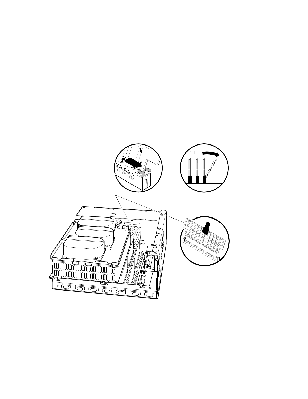
8. Remove all SIMMs from the CPU module. (See Figure 2–7).
Caution
Static electricity can damage integrated circuits. Wear a wrist strap
and place an antistatic mat under the system unit when working with
the internal parts of the system unit.
Note
Note carefully the position of each SIMM you remove; they must be
reinstalled later into the same slots.
Beginning with the SIMMs closest to the front of the enclosure remove
each as follows:
1. Release the memory module by pressing the metal board clips on the
memory module connector away from the center.
2. Tip the memory module rearward.
2–10 Upgrading the VAX 4000 Model 100 System
Page 23
Upgrading the VAX 4000 Model 100 System
2.5 Replacing the CPU Module
3. Lift the memory module up and out of the enclosure, and place it on an
anti-static mat.
Figure 2–7 Removing a SIMM
Metal Board Clip
MS44 Memory Modules
MLO-009876
Upgrading the VAX 4000 Model 100 System 2–11
Page 24
Upgrading the VAX 4000 Model 100 System
2.5 Replacing the CPU Module
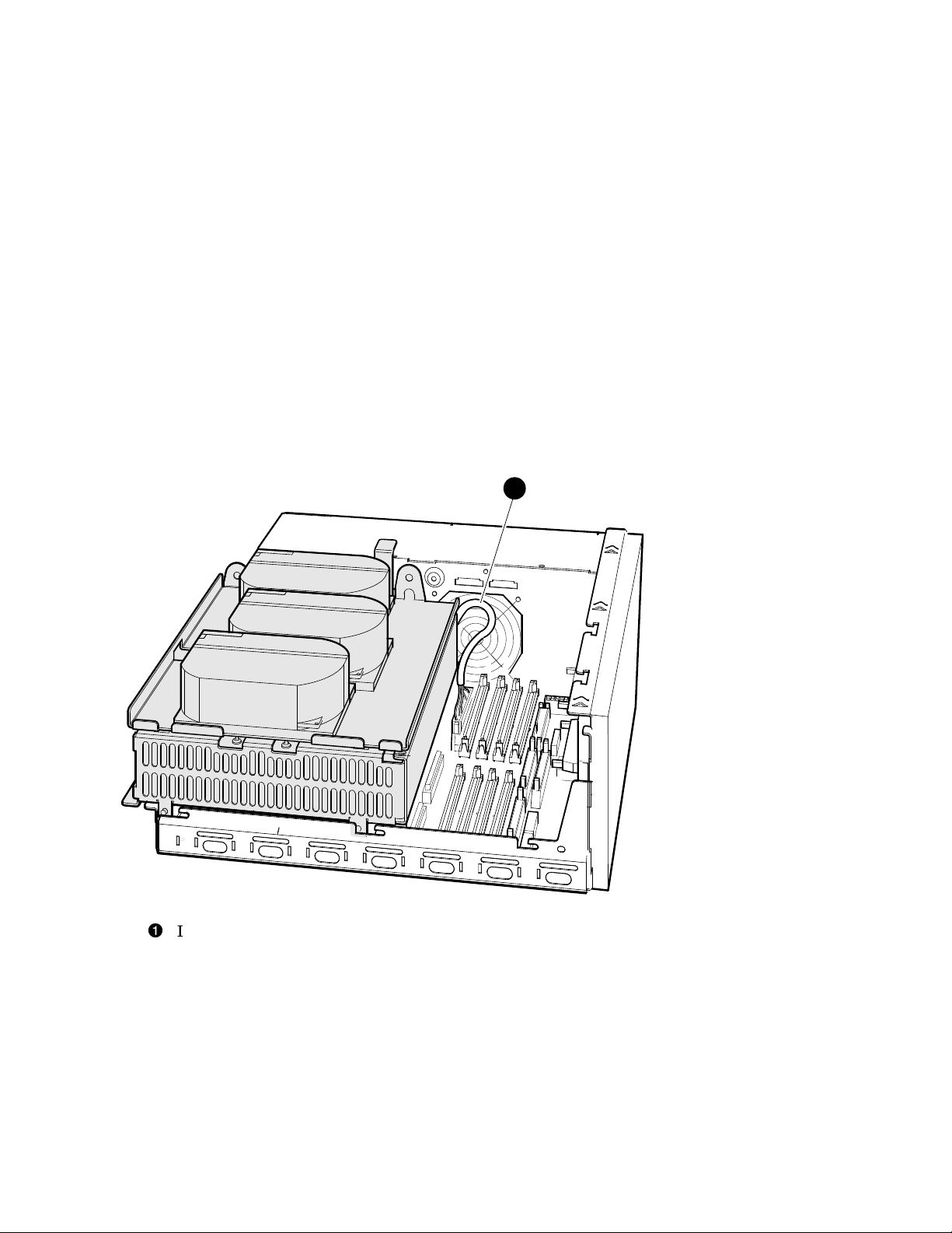
9. Disconnect the internal SCSI cable from the CPU module (see Figure 2–8).
Figure 2–8 Disconnecting the Internal SCSI Cable from the CPU Module
1
Internal SCSI cable
2–12 Upgrading the VAX 4000 Model 100 System
MLO-012288
Page 25
Upgrading the VAX 4000 Model 100 System
2.5 Replacing the CPU Module
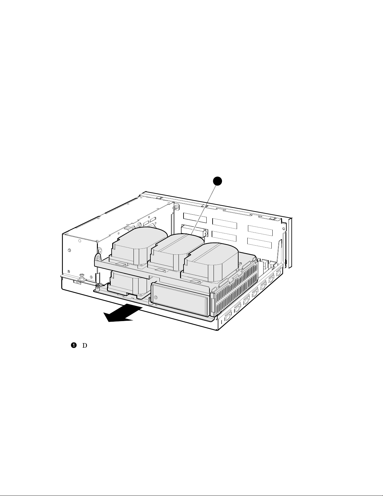
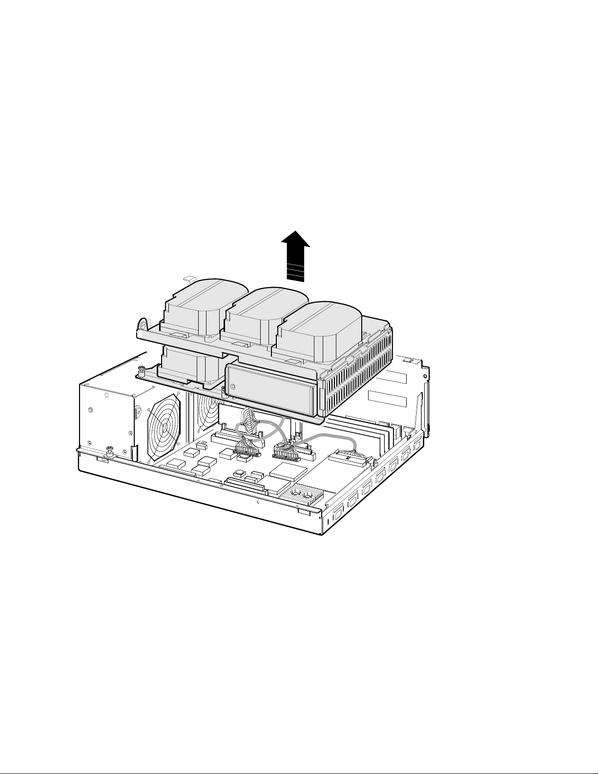
10. Remove the shelves by sliding them forward (see Figure 2–9) and lifting
them up from the enclosure (see Figure 2–10).
Figure 2–9 Sliding the Drive Mounting Shelves Forward
1
Drive mounting shelves
MLO-010806
Upgrading the VAX 4000 Model 100 System 2–13
Page 26
Upgrading the VAX 4000 Model 100 System
2.5 Replacing the CPU Module
Figure 2–10 Lifting the Drive Mounting Shelves Upward
2–14 Upgrading the VAX 4000 Model 100 System
MLO-010807
Page 27
Upgrading the VAX 4000 Model 100 System
2.5 Replacing the CPU Module
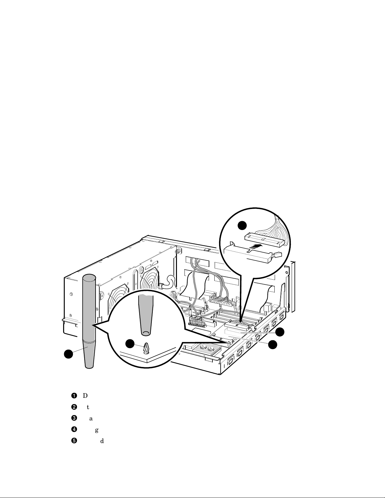
11. Disconnect the DSSI cable(s) from the DSSI daughter card (see
Figure 2–11).
12. Remove the DSSI daughter card by gently prying it loose from its connector
on the CPU module, and use a standoff removal tool to compress the posts
so that each corner of the card can be lifted off individually (Figure 2–11).
When all four corners are loose, lift the card out and place it on an
anti-static mat.
Figure 2–11 Removing the DSSI Daughter Card
1
3
2
DSSI connector
Standoff removal tool
Standoff
Daughter card connector on the CPU module
DSSI daughter card
Upgrading the VAX 4000 Model 100 System 2–15
4
5
MLO-012290
Page 28
Upgrading the VAX 4000 Model 100 System
2.5 Replacing the CPU Module
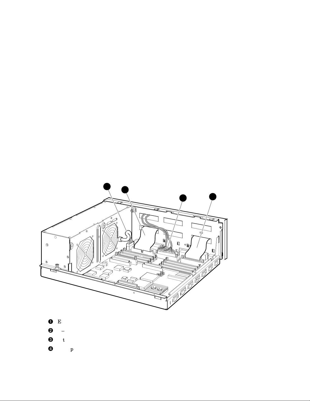
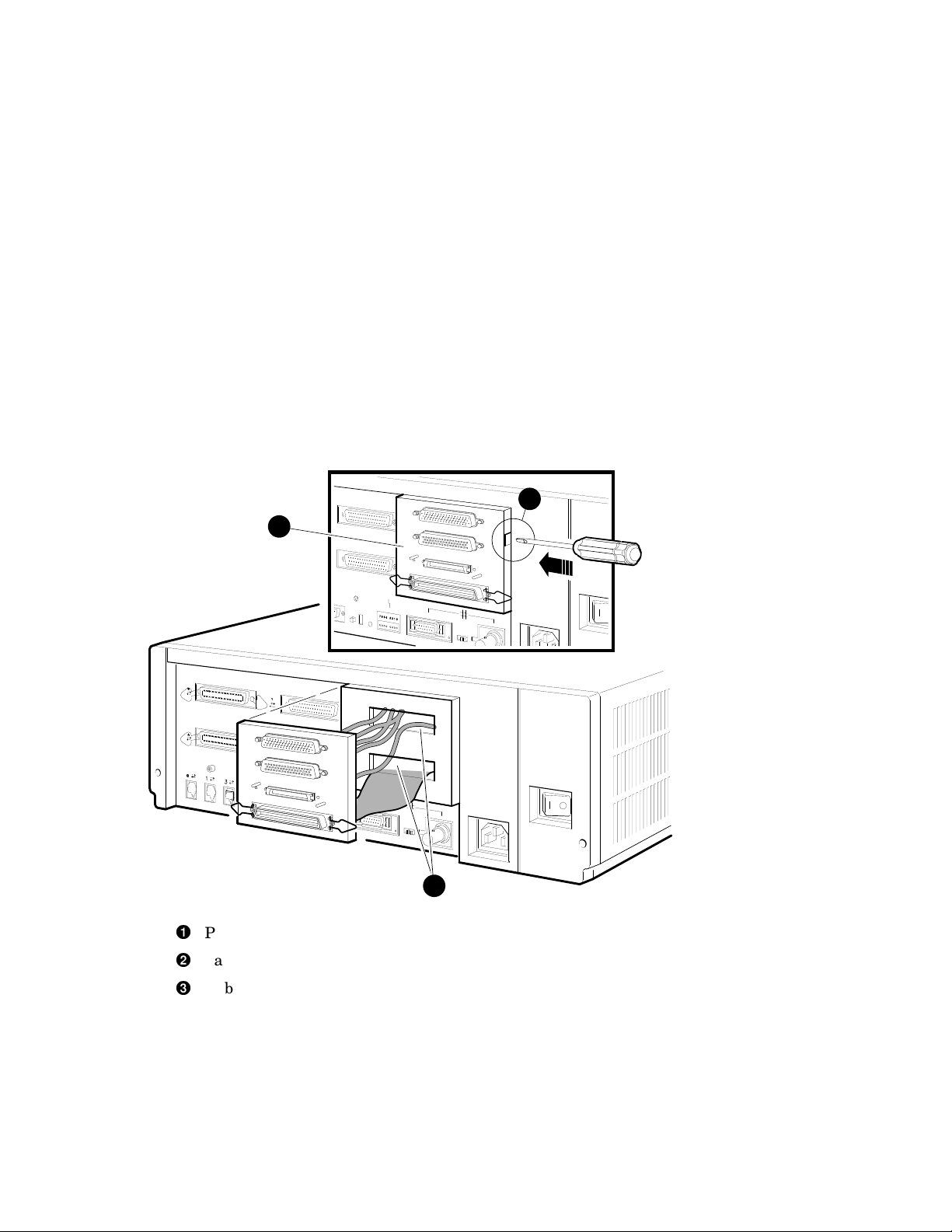
13. Remove all cables from the CPU module (Figure 2–12).
a. Disconnect the external SCSI cable, which runs from the port cover to
the CPU module, at the connector on the CPU module.
b. Disconnect the Q–bus cable.
c. Disconnect any internal communications options cables that are
present in your system from the CPU module.
d. Disconnect the CPU power cable from the CPU module.
Figure 2–12 Disconnecting the Q–bus and external SCSI Cables
4
1
External SCSI cable
Q–bus cable
Internal communications option cable(s)
CPU power cable
2
3
MLO-012291
2–16 Upgrading the VAX 4000 Model 100 System
Page 29
Upgrading the VAX 4000 Model 100 System
2.5 Replacing the CPU Module
14. Remove the present port cover by pushing the tabs on each side (see
Figure 2–13). The tabs are accessed through the tab cutouts on the port
cover. Slide the cover off, pulling all cables carefully through the cable slots
on the rear of the system box.
Figure 2–13 Removing the Port Cover
2
1
Port cover
Tab cutout
Cable slots on rear of the system box
Upgrading the VAX 4000 Model 100 System 2–17
3
MLO-010813
Page 30

Upgrading the VAX 4000 Model 100 System
2.5 Replacing the CPU Module
15. Remove all connectors from the original port cover (see Figure 2–14). Save
the screws, nuts, and washers for use in connecting the new port cover.
Figure 2–14 Removing Connectors from the Port Cover
1
2
Nut driver used for bolts on the Q–bus connectors
Phillips screwdriver used on the DSSI and SCSI connectors
MLO-010814
2–18 Upgrading the VAX 4000 Model 100 System
Page 31

Upgrading the VAX 4000 Model 100 System
2.5 Replacing the CPU Module
16. Install two alignment pins with washers on the new port cover for the
original DSSI connector (see Figure 2–15).
Figure 2–15 Installing the Alignment Pins on the Port Cover
1
2
Alignment pin
Washer
MLO-010815
Upgrading the VAX 4000 Model 100 System 2–19
Page 32

Upgrading the VAX 4000 Model 100 System
2.5 Replacing the CPU Module
17. Install the single DSSI cable (17–03544–01) into the left DSSI port cutout
(see Figure 2–16).
Figure 2–16 Installing the Original DSSI Cable on the Port Cover
2
1
Original DSSI cable connector
Pillips screwdriver
2–20 Upgrading the VAX 4000 Model 100 System
MLO-010816
Page 33

Upgrading the VAX 4000 Model 100 System
2.5 Replacing the CPU Module
18. Install the Q–bus cable (17–03545–01) into the Q–bus cutouts on the port
cover (see Figure 2–17).
Figure 2–17 Installing the Q–bus Cable on the Port Cover
2
3
1
Q–bus cable connectors
Nutdriver and bolt
Washer
MLO-010817
Upgrading the VAX 4000 Model 100 System 2–21
Page 34

Upgrading the VAX 4000 Model 100 System
2.5 Replacing the CPU Module
19. Install the blank covers into the two right DSSI external cutouts on the
new port cover (see Figure 2–18).
Figure 2–18 Installing the Blank Covers on the Port Cover
2
1
Blank covers
Phillips screwdriver and screw.
2–22 Upgrading the VAX 4000 Model 100 System
MLO-012292
Page 35

Upgrading the VAX 4000 Model 100 System
2.5 Replacing the CPU Module
20. Install the SCSI cable (17–2944–01) into the SCSI cutout on the bottom of
the port cover (see Figure 2–19).
Figure 2–19 Installing the SCSI Cable on the Port Cover
1
SCSI cable connector
Phillips screwdriver and screw
Washer
3
2
MLO-012293
Upgrading the VAX 4000 Model 100 System 2–23
Page 36

Upgrading the VAX 4000 Model 100 System
2.5 Replacing the CPU Module
21. Install the new port cover with its connectors onto the rear of the system
box, feeding the cables through the cable cutouts in the system box (see
Figure 2–20).
a. Feed the single DSSI cable and the Q–bus cables through the top cable
cutout on the system box.
b. Feed the SCSI cable through the bottom cable cutout on the system
box.
c. Hook the bottom flange of the cover plate onto the system box.
d. Push the port cover forward until the two tabs click into place.
Figure 2–20 Installing the Port Cover and Cables
1
3
DSSI and Q–bus cables in top cutout
SCSI cable in bottom cutout
Bottom flange
Tab cutout
2–24 Upgrading the VAX 4000 Model 100 System
4
2
MLO-012294
Page 37

Upgrading the VAX 4000 Model 100 System
2.5 Replacing the CPU Module
22. To remove the CPU module, follow these steps.
Caution
Ensure that you do not damage any of the CPU module components by
exerting too much force on them.
a. Press the two spring clips (marked by arrows in Figure 2–21) that
secure the CPU module in position. The CPU module moves forward
under the tension of the connector gaskets. If necessary, slide the CPU
module back until it disengages from the ten keyhole cutouts (refer to
Figure 2–21).
b. Use your finger, in the semicircular cutout on the front edge of the
CPU module, to lift up the front edge of the CPU module (refer to
Figure 2–21).
c. While supporting the front of the CPU module with one hand, guide
the connectors on the back of the CPU module out of the corresponding
cutouts on the back of the enclosure.
d. Remove the CPU module from the enclosure.
Upgrading the VAX 4000 Model 100 System 2–25
Page 38

Upgrading the VAX 4000 Model 100 System
2.5 Replacing the CPU Module
Figure 2–21 Removing the CPU Module
3
1
PUSH PUSH
2
Spring clips
Semicircular cutout
Keyhole cutouts (10)
2–26 Upgrading the VAX 4000 Model 100 System
MLO-012295
Page 39

Upgrading the VAX 4000 Model 100 System
2.5 Replacing the CPU Module
23. To install the new CPU module, follow these steps:
a. Place the CPU module in the enclosure so that the connectors on the
CPU module align with the corresponding cutouts in the back panel of
the enclosure. Use the ThinWire Ethernet port as an anchor point to
adjust the position of the CPU module correctly.
b. Align the keyhole cutouts in the CPU module with the corresponding
standoff pillars in the base of the enclosure.
Caution
Ensure that you do not damage any of the CPU module components by
exerting pressure on them.
c. Press the CPU module at the two positions marked push. The spring
clips push the standoff pillars into the keyhole cutouts that secure the
CPU module in position. See Figure 2–21.
24. Install the DSSI daughter card onto the CPU module (see Figure 2–22).
Align the card on the standoffs so that it is positioned above the CPU
module connector, then gently seat it onto the connector and the standoffs.
Upgrading the VAX 4000 Model 100 System 2–27
Page 40

Upgrading the VAX 4000 Model 100 System
2.5 Replacing the CPU Module
Figure 2–22 Installing the DSSI Daughter Card
1
Daughter card
Standoff
CPU module connector
For clarity, cables not applicable to a particular step are omitted from
some of the following illustrations.
2–28 Upgrading the VAX 4000 Model 100 System
3
2
MLO-012296
Note
Page 41

Upgrading the VAX 4000 Model 100 System
2.5 Replacing the CPU Module
25. Connect the external SCSI cable (17–2944–01) to the CPU module (see
Figure 2–23).
Figure 2–23 Connecting the External SCSI Cable to the CPU Module
1
2
External SCSI cable
External SCSI connector on the CPU module
Upgrading the VAX 4000 Model 100 System 2–29
MLO-012297
Page 42

Upgrading the VAX 4000 Model 100 System
2.5 Replacing the CPU Module
26. Connect the DSSI cable (17–03544–01) to the connector slot on the DSSI
daughter card (see Figure 2–24).
Figure 2–24 Connecting the Single DSSI Cable to the Daughter Card
Single DSSI cable
Rear connector slot on the daughter card
1
2
MLO-012298
2–30 Upgrading the VAX 4000 Model 100 System
Page 43

Upgrading the VAX 4000 Model 100 System
2.5 Replacing the CPU Module
27. Connect the Q–bus cable (17–3545–01) to the Q–bus slot on the CPU
module (see Figure 2–25).
Figure 2–25 Connecting the Q–bus Cable to the CPU Module
1
2
Q–bus cable
Q–bus connector on the CPU module
Upgrading the VAX 4000 Model 100 System 2–31
MLO-012299
Page 44

Upgrading the VAX 4000 Model 100 System
2.5 Replacing the CPU Module
28. Reinstall the upper and lower drive mounting shelves in the system box,
and connect the internal SCSI cable (17–03587–01) to the CPU module.
a. Position the shelves by lining up the bracket tabs, but do not slide
them rearward yet (see Figure 2–26).
Figure 2–26 Aligning the Drive Mounting Shelves
Bracket tabs
2–32 Upgrading the VAX 4000 Model 100 System
1
MLO-012300
Page 45

Upgrading the VAX 4000 Model 100 System
2.5 Replacing the CPU Module
b. Connect the internal SCSI cable to its connector on the CPU module.
(see Figure 2–27).
c. Slide the shelves down and rearward into place so that the holes on the
bracket tabs line up with their cutouts.
Figure 2–27 Reinstalling the Drive Mounting Shelves
1
Internal SCSI cable
MLO-012301
Upgrading the VAX 4000 Model 100 System 2–33
Page 46

Upgrading the VAX 4000 Model 100 System
2.5 Replacing the CPU Module
d. Tighten the shelves in place using the six screws that held them in
originally (see Figure 2–28).
1. Tighten the topmost captive screw first so that the shelves do not
fall and damage components underneath.
2. Tighten the remaining captive screws.
3. Replace and tighten the Phillips screws.
Figure 2–28 Securing the Drive Mounting Shelves
1
2
Topmost captive screw
Other captive screws
2–34 Upgrading the VAX 4000 Model 100 System
3
MLO-012302
Phillips screws
Page 47

Upgrading the VAX 4000 Model 100 System
2.5 Replacing the CPU Module
29. Reinstall the SIMMs as follows, beginning with the module closest to the
front of the enclosure (Figure 2–29).
Caution
When installing a SIMM, note that the connectors on the CPU module
are keyed so that you cannot install the module with an incorrect
orientation. Do not try to force a module into a connector with an
incorrect orientation.
Note
The SIMMs must be reinstalled into the same slots they came from.
1. Tip the memory module rearward.
2. Slide the module into its connector while still tipped rearward, and tip
it back upright.
Upgrading the VAX 4000 Model 100 System 2–35
Page 48

Upgrading the VAX 4000 Model 100 System
2.5 Replacing the CPU Module
Figure 2–29 Installing a SIMM
1
2
Sliding the module in
2–36 Upgrading the VAX 4000 Model 100 System
MLO-012303
Tipping it upright
Page 49

Upgrading the VAX 4000 Model 100 System
2.5 Replacing the CPU Module
30. Reconnect the DSSI connectors to the drives (see Figure 2–6).
31. Reconnect the internal power cables (see Figure 2–5).
32. Reinstall the enclosure cover (see Figure 2–3).
33. Reconnect cables and terminators to the DSSI, Q–bus, and SCSI connectors
on the port cover as desired (see Figure 2–30).
Figure 2–30 Reconnecting Cables and Terminators
1
1
3
2
2
DSSI connector/terminator
Q–bus connectors
SCSI connector/terminator
3
MLO-012310
Upgrading the VAX 4000 Model 100 System 2–37
Page 50

Upgrading the VAX 4000 Model 100 System
2.5 Replacing the CPU Module
34. Replace the Ethernet connector, if any (see Figure 2–2).
35. Place the new label, 36–30382–23 (24), whichever is appropriate for your
country, over the existing label.
36. Remove the system medallion and install the new one, 74–37642–32. See
Figure 2–31.
a. Peel the backing off the new medallion.
b. Apply the new medallion in place of the original one.
Figure 2–31 Applying the New Medallion
1
2
3
Backing
New medallion
Medallion location
37. Apply the conversion label (36–15946–00) in any spot on the system box
you wish.
38. Have the customer reinstall system data (if necessary).
39. Fill out the forms in Appendix A.
40. Return the original CPU module as instructed (see Appendix A).
2–38 Upgrading the VAX 4000 Model 100 System
MLO-010951
Page 51

Upgrading the VAX 4000 Model 100A
3.1 In This Chapter
This chapter lists detailed step-by-step procedures for upgrading a VAX Model
100A system to a VAX Model 105A system.
3.2 Procedure Overview
The conversion procedure is summarized next. To begin the actual conversion,
turn to Section 3.3.
1. Have the customer back up the system software.
2. Unpack and verify the conversion kit.
3. Shut down the operating system and run the power up diagnostics.
4. Turn off the system power and remove the power cord.
5. Remove the enclosure cover.
3
System
6. Remove the SIMMs (memory modules).
7. Remove the upper and lower drive mounting shelves.
8. Disconnect and remove the DSSI daughter card.
9. Disconnect all internal cables from the port cover to the CPU module,
daughter cards and the drives.
10. Remove the CPU module.
11. Install the new CPU module.
12. Reinstall the SIMMs.
13. Reconnect all cables and daughter cards to the CPU module.
14. Reinstall the upper and lower drive mounting shelves in the system box,
and reconnect all cables.
Upgrading the VAX 4000 Model 100A System 3–1
Page 52

Upgrading the VAX 4000 Model 100A System
3.2 Procedure Overview
15. Reinstall the enclosure cover.
16. Connect the power cable, signal cables, and terminators to the system as
desired.
17. Turn on the system.
18. Have the customer reinstall system data (if necessary).
19. Fill out the forms in Appendix A.
20. Return the CPU module as instructed (see Appendix A).
Note
Firmware and VMS upgrades are not required; appropriate versions
were installed on VAX 4000 Model 100A systems at the factory.
3.3 Unpacking the Kit
Unpack the kit as follows:
1. Make sure there is no external damage to the shipping container, such as
dents, holes, or crushed corners.
2. Unpack the conversion kit and check its contents against the shipping
invoice. Table 3–1 lists the kit contents for the Model 100/100A upgrade to
Model 105A, 53XR–AA. Other items may be present, but are not required
for this conversion.
Static discharge can damage modules. Use an antistatic wrist strap
and antistatic mat during handling. The wrist strap and mat are in
the antistatic kit in the Digital Services toolkit.
3. Unpack the CPU module and place it on a grounded antistatic mat.
4. Save the packing material, and use it to return the original CPU module.
3–2 Upgrading the VAX 4000 Model 100A System
CAUTION
Page 53

Upgrading the VAX 4000 Model 100A System
3.3 Unpacking the Kit
5. If any item is missing or damaged:
• Contact the customer’s sales representative.
• Contact the customer’s delivery agent.
Table 3–1 Contents of the 53XR–AA Upgrade Kit
Description Part Number Quantity
Wire harness assy 17–03615–001 1
Product conversion label 36–15946–00 1
Regulatory label 36–30382–23(24) 1
NVAX CPU 54–21797–02 1
Medallion 74–37642–32 1
DSSI blank panel 74–46956–01 2
Expansion port cover 74–46957–01 1
Machine screw, 8mm 90–10917–01 4
VAX 4000 100/100A Upgrade to
Model 105A
VMS multimedia Viking QA–001AA–UW 1
Model 105A doc set QZ–K04AB–GZ 1
EK–V411A–CG 1
3.4 Before Installing the Kit
Before installing the kit:
1. Have the customer back up the system software before the Digital Services
representative arrives. It is the customer’s responsibility to back up the
system software.
2. Shut down the operating system in the proper manner.
3. Power up the system and run diagnostics to verify system operation.
4. Turn off the system power before installing the kit.
Upgrading the VAX 4000 Model 100A System 3–3
Page 54

Upgrading the VAX 4000 Model 100A System
3.5 Installing the CPU Module
3.5 Installing the CPU Module
To install the new CPU module (convert to a VAX 4000 Model 105A):
1. Disconnect the power cord from the wall outlet, then from the system (see
Figure 3–1).
Figure 3–1 Disconnecting the Power Cord
1
1
3
2
Power cord
3–4 Upgrading the VAX 4000 Model 100A System
MLO-010952
Page 55

Upgrading the VAX 4000 Model 100A System
3.5 Installing the CPU Module
2. Remove the enclosure cover by removing the two screws at the rear of the
system box and sliding it forward (see Figure 3–2).
Figure 3–2 Removing the Enclosure Cover
2
1
3
2
Screws
Enclosure cover
1
MLO-010953
Upgrading the VAX 4000 Model 100A System 3–5
Page 56

Upgrading the VAX 4000 Model 100A System
3.5 Installing the CPU Module
3. Remove the upper and lower drive mounting shelves together as a single
unit (it is not necessary to disassemble the shelves themselves). Unscrew
all six screws from the shelves, leaving the topmost captive screw until
last for support. Leave the capitve screws in position and save the Phillips
screws for reinstallation of the shelves (see Figure 3–3).
Figure 3–3 Unscrewing the Drive Shelves
1
2
Topmost captive screw
Other captive screws
Phillips screws
3–6 Upgrading the VAX 4000 Model 100A System
3
MLO-012302
Page 57

Upgrading the VAX 4000 Model 100A System
3.5 Installing the CPU Module
4. Disconnect the internal power cables from the power supply (Figure 3–4).
5. Disconnect the pigtailed, 2-pin DSSI power cable from the CPU module.
(Figure 3–4).
Upgrading the VAX 4000 Model 100A System 3–7
Page 58

Upgrading the VAX 4000 Model 100A System
3.5 Installing the CPU Module
Figure 3–4 Disconnecting the Internal Power Cables
1
2 3
Internal power cable
Internal power cable with pigtailed DSSI power cable
CPU module DSSI power cable connector
3–8 Upgrading the VAX 4000 Model 100A System
MLO-012306
Page 59

Upgrading the VAX 4000 Model 100A System
3.5 Installing the CPU Module
6. Disconnect the internal DSSI connectors from all drives mounted on the
shelves. Figure 3–5 shows one drive as an example.
Figure 3–5 Disconnecting Internal DSSI Connectors
1
MLO-010804
Internal DSSI connectors
7. Remove all SIMMs from the CPU module. (See Figure 3–6).
Caution
Static electricity can damage integrated circuits. Wear a wrist strap
and place an antistatic mat under the system unit when working with
the internal parts of the system unit.
Note
Note carefully the position of each memory module you remove; they
must be reinstalled later into the same slots.
Beginning with the SIMMs closest to the front of the enclosure remove
each as follows:
1. Release the memory module by pressing the metal board clips on the
memory module connector away from the center.
2. Tip the memory module rearward.
Upgrading the VAX 4000 Model 100A System 3–9
Page 60

Upgrading the VAX 4000 Model 100A System
3.5 Installing the CPU Module
3. Lift the memory module up and out of the enclosure, and place it on an
anti-static mat.
Figure 3–6 Removing a SIMM
Metal Board Clip
MS44 Memory Modules
3–10 Upgrading the VAX 4000 Model 100A System
MLO-012304
Page 61

Upgrading the VAX 4000 Model 100A System
3.5 Installing the CPU Module
8. Disconnect the internal SCSI cable from the CPU module (see Figure 3–7).
Figure 3–7 Disconnecting the Internal SCSI Cable from the CPU Module
1
Internal SCSI cable
MLO-012305
Upgrading the VAX 4000 Model 100A System 3–11
Page 62

Upgrading the VAX 4000 Model 100A System
3.5 Installing the CPU Module
9. Remove the shelves by sliding them forward (see Figure 3–8) and lifting
them forward and up from the enclosure (see Figure 3–9).
Figure 3–8 Sliding the Drive Mounting Shelves Forward
1
Drive mounting shelves
3–12 Upgrading the VAX 4000 Model 100A System
MLO-012307
Page 63

Upgrading the VAX 4000 Model 100A System
3.5 Installing the CPU Module
Figure 3–9 Lifting the Drive Mounting Shelves Upward
MLO-012289
Upgrading the VAX 4000 Model 100A System 3–13
Page 64

Upgrading the VAX 4000 Model 100A System
3.5 Installing the CPU Module
10. Disconnect the DSSI cable from the DSSI daughter card (see Figure 3–10).
11. Remove the DSSI daughter card by gently prying it loose from its connector
on the CPU module, and use a standoff removal tool to compress the posts
so that each corner of the card can be lifted off individually (Figure 3–10).
When all four corners are loose, lift the card out and place it on an
anti-static mat.
Figure 3–10 Removing the DSSI Daughter Card
1
3
2
DSSI connector
Standoff removal tool
Standoff
Daughter card connector on the CPU module
Single DSSI daughter card
3–14 Upgrading the VAX 4000 Model 100A System
4
5
MLO-012311
Page 65

Upgrading the VAX 4000 Model 100A System
3.5 Installing the CPU Module
12. Remove all cables from the CPU module (Figure 3–11).
a. Disconnect the external SCSI cable, which runs from the port cover to
the CPU module, at the connector on the CPU module.
b. Disconnect the Q–bus cable.
c. Disconnect any internal communications options cables that are
present in your system from the CPU module.
d. Disconnect the CPU power cable from the CPU module.
Figure 3–11 Disconnecting the Q–bus and external SCSI Cables
4
1
External SCSI cable
Q–bus cable
Internal communications option cable(s)
CPU power cable
2
3
MLO-012308
Upgrading the VAX 4000 Model 100A System 3–15
Page 66

Upgrading the VAX 4000 Model 100A System
3.5 Installing the CPU Module
13. To remove the CPU module, follow these steps.
Caution
Ensure that you do not damage any of the CPU module components by
exerting too much force on them.
a. Press the two spring clips (marked by arrows in Figure 3–12) that
secure the CPU module in position. The CPU module moves forward
under the tension of the connector gaskets. If necessary, slide the CPU
module back until it disengages from the ten keyhole cutouts (refer to
Figure 3–12).
b. Use your finger, in the semicircular cutout on the front edge of the
CPU module, to lift up the front edge of the CPU module (refer to
Figure 3–12).
c. While supporting the front of the CPU module with one hand, guide
the connectors on the back of the CPU module out of the corresponding
cutouts on the back of the enclosure.
d. Remove the CPU module from the enclosure.
3–16 Upgrading the VAX 4000 Model 100A System
Page 67

Upgrading the VAX 4000 Model 100A System
Figure 3–12 Removing the CPU Module
3
1
3.5 Installing the CPU Module
PUSH PUSH
2
Spring clips
Semicircular cutout
Keyhole cutouts (10)
MLO-012295
Upgrading the VAX 4000 Model 100A System 3–17
Page 68

Upgrading the VAX 4000 Model 100A System
3.5 Installing the CPU Module
14. To install the new CPU module, follow these steps:
a. Place the CPU module in the enclosure so that the connectors on the
CPU module align with the corresponding cutouts in the back panel of
the enclosure. Use the ThinWire Ethernet port as an anchor point to
adjust the position of the CPU module correctly.
b. Align the keyhole cutouts in the CPU module with the corresponding
standoff pillars in the base of the enclosure.
Caution
Ensure that you do not damage any of the CPU module components by
exerting pressure on them.
c. Press the CPU module at the two positions marked push. The spring
clips push the standoff pillars into the keyhole cutouts that secure the
CPU module in position. See Figure 3–12.
15. Install the DSSI daughter card onto the CPU module (see Figure 3–13).
Align the card on the standoffs so that it is positioned above the CPU
module connector, then gently seat it onto the connector and the standoffs.
3–18 Upgrading the VAX 4000 Model 100A System
Page 69

Upgrading the VAX 4000 Model 100A System
3.5 Installing the CPU Module
Figure 3–13 Installing the DSSI Daughter Card
1
3
2
MLO-012296
Daughter card
Standoff
CPU module connector
Note
For clarity, cables not applicable to a particular step are omitted from
some of the following illustrations.
Upgrading the VAX 4000 Model 100A System 3–19
Page 70

Upgrading the VAX 4000 Model 100A System
3.5 Installing the CPU Module
16. Connect the external SCSI cable (17–2944–01) to the CPU module (see
Figure 3–14).
Figure 3–14 Connecting the External SCSI Cable to the CPU Module
1
2
External SCSI cable
External SCSI connector on the CPU module
3–20 Upgrading the VAX 4000 Model 100A System
MLO-012297
Page 71

Upgrading the VAX 4000 Model 100A System
3.5 Installing the CPU Module
17. Connect the DSSI cable (17–03544–01) to the connector slot on the DSSI
daughter card (see Figure 3–15).
Figure 3–15 Connecting the Single DSSI Cable to the Daughter Card
Single DSSI cable
Rear connector slot on the daughter card
Note
1
2
MLO-012298
If your system has the dual DSSI option, run the dual DSSI in/out
cable (17–03778–01) between the rows of memory module slots and
connect it to the front connector slot on the DSSI daughter card (closest
to the front of the enclosure).
Upgrading the VAX 4000 Model 100A System 3–21
Page 72

Upgrading the VAX 4000 Model 100A System
3.5 Installing the CPU Module
18. Connect the Q–bus cable (17–3545–01) to the Q–bus slot on the CPU
module (see Figure 3–16).
Figure 3–16 Connecting the Q–bus Cable to the CPU Module
1
2
Q–bus cable
Q–bus connector on the CPU module
3–22 Upgrading the VAX 4000 Model 100A System
MLO-012299
Page 73

Upgrading the VAX 4000 Model 100A System
3.5 Installing the CPU Module
19. Reinstall the upper and lower drive mounting shelves in the system box,
and connect the internal SCSI cable (17–03587–01) to the CPU module.
a. Position the shelves by lining up the bracket tabs, but do not slide
them rearward yet (see Figure 3–17).
Figure 3–17 Aligning the Drive Mounting Shelves
Bracket tabs
1
MLO-012300
Upgrading the VAX 4000 Model 100A System 3–23
Page 74

Upgrading the VAX 4000 Model 100A System
3.5 Installing the CPU Module
b. Connect the internal SCSI cable to its connector on the CPU module
(see Figure 3–18).
c. Slide the shelves down and rearward into place so that the holes on the
bracket tabs line up with their cutouts.
Figure 3–18 Reinstalling the Drive Mounting Shelves
1
Internal SCSI cable
3–24 Upgrading the VAX 4000 Model 100A System
MLO-012305
Page 75

Upgrading the VAX 4000 Model 100A System
3.5 Installing the CPU Module
d. Tighten the shelves in place using the six screws that held them in
originally (see Figure 3–19).
1. Tighten the topmost captive screw first so that the shelves do not
fall and damage components underneath.
2. Tighten the remaining captive screws.
3. Replace and tighten the Phillips screws.
Figure 3–19 Securing the Drive Mounting Shelves
1
2
Topmost captive screw
Other captive screws
3
MLO-012302
Phillips screws
Upgrading the VAX 4000 Model 100A System 3–25
Page 76

Upgrading the VAX 4000 Model 100A System
3.5 Installing the CPU Module
20. Reinstall the SIMMs as follows, beginning with the module closest to the
front of the enclosure (Figure 3–20).
Caution
When installing a SIMM, note that the connectors on the CPU module
are keyed so that you cannot install the module with an incorrect
orientation. Do not try to force a module into a connector with an
incorrect orientation.
Note
The SIMMs must be reinstalled into the same slots they came from.
1. Tip the memory module rearward.
2. Slide the module into its connector while still tipped rearward, and tip
it back upright.
3–26 Upgrading the VAX 4000 Model 100A System
Page 77

Upgrading the VAX 4000 Model 100A System
Figure 3–20 Installing a Memory Module
3.5 Installing the CPU Module
1
2
Sliding the module in
MLO-012303
Tipping it upright
Upgrading the VAX 4000 Model 100A System 3–27
Page 78

Upgrading the VAX 4000 Model 100A System
3.5 Installing the CPU Module
21. Reconnect the DSSI connectors to the drives (see Figure 3–5).
22. Reconnect the internal power cables (see Figure 3–4).
23. Reinstall the enclosure cover (see Figure 3–2).
24. Place the new label, 36–30382–23 (24), whichever is appropriate for your
country, over the existing label.
25. Remove the system medallion and install the new one, 74–37642–32. See
Figure 3–21.
a. Peel the backing off the new medallion.
b. Apply the new medallion in place of the original one.
Figure 3–21 Applying the New Medallion
1
2
3
Backing
New medallion
Medallion location
3–28 Upgrading the VAX 4000 Model 100A System
MLO-010951
Page 79

Upgrading the VAX 4000 Model 100A System
3.5 Installing the CPU Module
26. Apply the conversion label (36–15946–00) in any spot on the system box
you wish.
27. Have the customer reinstall system data (if necessary).
28. Fill out the forms in Appendix A.
29. Return the original CPU module as instructed (see Appendix A).
Upgrading the VAX 4000 Model 100A System 3–29
Page 80

Page 81

Mandatory Return Procedure and Forms
The original CPU module must be returned to Digital Equipment Corporation.
Digital Services personnel must follow the instructions for repackaging and
returning the original CPU. The instructions apply only to United States area
installations.
For installations outside the United States area, contact the local Digital
Equipment Corporation office for return destination instructions.
A.1 Return Procedure
Note
Customers who do not return their original CPU modules will be
charged a fee.
Return the original CPU module as follows:
1. Obtain the serial number of the system being converted. Customer
Administrative Services (CAS) cannot process the order without this serial
number.
A
2. Ensure that the serial number is on the purchase order.
3. Issue a hardcopy quotation to the customer, referencing the serial number,
and state the following:
"Return of the replaced modules to Digital is a condition of sale for
this conversion. Failure to return the modules will result in a penalty
charge. Installation of hardware by Digital Services personnel is
required."
4. Pack the original CPU module using the packaging material set aside from
the carton of the conversion kit.
Mandatory Return Procedure and Forms A–1
Page 82

Mandatory Return Procedure and Forms
A.1 Return Procedure
Pack the module first in the nickel-plated bag, then in the pink plastic
wrapping, and finally in the box. Do not seal the box for shipping until you
have included all necessary paperwork.
5. Complete the Digital Services Worksheet in Section A.2. It documents the
work you performed.
Return the worksheet to your contract administrator at the branch office.
6. Contact your local Digital CAS office to obtain information for the
Installation Receipt and the Return Material Checklist in Section A.2.
Ask the CAS representative for a return authorization (RA) number. CAS
will contact the customer to arrange for carrier pickup and return of the
module to Digital Equipment Corporation.
7. Complete both copies of the Installation Receipt.
The first copy is the customer’s receipt. It shows that the installation was
completed and that Digital Services contacted CAS.
Return the second copy to Digital Services along with the original CPU
module card so that the customer does not incur a penalty charge.
8. Complete the Returned Material Checklist.
Return the checklist with the original module.
9. Place the self-adhesive mailing label on the box to be returned.
Write the return authorization (RA) number in the space provided on the
label.
10. Seal the box for shipment.
Refer questions regarding the return procedure to the local account
representative.
A.2 Return Forms
This section contains the:
• Digital Services Worksheet
• Installation Receipt–Customer Copy
• Installation Receipt–Digital Services Copy
• Returned Material Checklist
A–2 Mandatory Return Procedure and Forms
Page 83

Mandatory Return Procedure and Forms
A.2 Return Forms
Digital Services Worksheet
This form acts as a verification of the work performed on the system and as a
check on the procedures used. Please fill out this form and return it to your
Contract Administrator for updating the customer’s contract.
Customer:
Previous System Model Number:
Previous System Serial Number:
Original CPU Module Serial Number:
New System Name:
New System Model Number:
New System Serial Number:
New CPU Module Serial Number:
Comments:
Mandatory Return Procedure and Forms A–3
Page 84

Mandatory Return Procedure and Forms
A.2 Return Forms
A–4 Mandatory Return Procedure and Forms
Page 85

Mandatory Return Procedure and Forms
A.2 Return Forms
Installation Receipt—Customer Copy
For the upgrade of VAX 4000 Model 100 or VAX 4000 Model 100A to VAX 4000
Model 105A.
This form acts as a customer receipt and as verification for Digital Services
that the CPU module upgrade kit was installed.
Digital Services: Complete both copies of this form. Give a copy to the customer and
Customer: Digital Equipment Corporation will contact you within the next
a copy to the local CAS office for filing with customer documents.
several days to arrange for package pickup and return. Keep
this copy as your record of installation by Digital Equipment
Corporation.
Note
Contact the local CAS office to obtain the RA (return authorization)
number. You should have the Digital order number available. Be sure
to note the name of the person you speak with.
Name of CAS representative:
Branch Office: , will arrange for package pickup and return.
Return Authorization (RA) Number:
Digital Order Number:
Original CPU Module Serial Number:
Converted to:
New System Serial Number:
New CPU Module Serial Number:
Installation was performed on this date:
(See overleaf for signatures)
Mandatory Return Procedure and Forms A–5
Page 86

Mandatory Return Procedure and Forms
A.2 Return Forms
CPU Module Packed for Return:
Customer Name: Phone Number:
Customer Signature:
Digital Services Representative Signature:
A–6 Mandatory Return Procedure and Forms
Page 87

Mandatory Return Procedure and Forms
A.2 Return Forms
Installation Receipt—Digital Services Copy
For the upgrade of VAX 4000 Model 100 or VAX 4000 Model 100A to a
VAX 4000 Model 105A.
This form acts as a verification for Digital Services that the CPU module
upgrade kit was installed.
Digital Services: Complete both copies of this form. Give a copy to the customer and
Contact the local CAS office to obtain the RA (return authorization)
number. You should have the Digital order number available. Be sure
to note the name of the person you speak with.
Name of CAS representative:
Branch Office: , will arrange for package pickup and return.
Return Authorization (RA) Number:
Digital Order Number:
Original CPU Module Serial Number:
Converted to:
New System Serial Number:
New CPU Module Serial Number:
a copy to the local CAS office for filing with customer documents.
Note
Installation was performed on this date:
(See overleaf for signatures)
Mandatory Return Procedure and Forms A–7
Page 88

Mandatory Return Procedure and Forms
A.2 Return Forms
CPU Module Packed for Return:
Customer Name: Phone Number:
Customer Signature:
Digital Services Representative Signature:
A–8 Mandatory Return Procedure and Forms
Page 89

Mandatory Return Procedure and Forms
A.2 Return Forms
Returned Material Checklist
For the upgrade of VAX 4000 Model 100 or VAX 4000 Model 100A to a
VAX 4000 Model 105A.
This form must be filled out and returned with the original daughter card to
ensure that the customer does not incur a penalty charge.
Return Authorization (RA) Number:
Digital Order Number:
Customer Name:
Customer Address:
Customer Contact:
********* Include This Form With Your Module Return*********
Mandatory Return Procedure and Forms A–9
Page 90

Page 91

How to Order Additional Documentation
Technical Support
If you need help deciding which documentation best meets your needs, call 800-DIGITAL
(800-344-4825) and press 2 for technical assistance.
Electronic Orders
If you wish to place an order through your account at the Electronic Store, dial
800-234-1998, using a modem set to 2400- or 9600-baud. You must be using a VT
terminal or terminal emulator set at 8 bits, no parity. If you need assistance using
the Electronic Store, call 800-DIGITAL (800-344-4825) and ask for an Electronic Store
specialist.
Telephone and Direct Mail Orders
From Call Write
U.S.A. DECdirect
Puerto Rico Phone: (809) 781-0505
Canada Phone: 800-267-6215
International ————— Local Digital subsidiary or
Internal Orders
(for software
documentation)
Internal Orders
(for hardware
documentation)
1
Phone: 800-DIGITAL
(800-344-4825)
Fax: (603) 884-5597
Fax: (809) 749-8377
Fax: (613) 592-1946
DTN: 264-3030
(603) 884-3030
Fax: (603) 884-3960
DTN: 264-3030
(603) 884-3030
Fax: (603) 884-3960
Digital Equipment Corporation
P.O. Box CS2008
Nashua, NH 03061
Digital Equipment Caribbean, Inc.
3 Digital Plaza, 1st Street
Suite 200
Metro Office Park
San Juan, Puerto Rico 00920
Digital Equipment of Canada Ltd.
100 Herzberg Road
Kanata, Ontario, Canada K2K 2A6
Attn: DECdirect Sales
approved distributor
U.S. Software Supply Business
Digital Equipment Corporation
10 Cotton Road
Nashua, NH 03063-1260
U.S. Software Supply Business
Digital Equipment Corporation
10 Cotton Road
Nashua, NH 03063-1260
1
Call to request an Internal Software Order Form (EN–01740–07).
Page 92

Page 93

Reader’s Comments VAX 4000
Model 100/100A Upgrade
Your comments and suggestions help us improve the quality of our publications.
Thank you for your assistance.
I rate this manual’s: Excellent Good Fair Poor
Accuracy (product works as manual says)
Completeness (enough information)
Clarity (easy to understand)
Organization (structure of subject matter)
Figures (useful)
Examples (useful)
Index (ability to find topic)
Page layout (easy to find information)
I would like to see more/less
What I like best about this manual is
What I like least about this manual is
to Model 105A
EK–V411A–CG. A01
I found the following errors in this manual:
Page Description
Additional comments or suggestions to improve this manual:
For software manuals, please indicate which version of the software you are using:
Name/Title Dept.
Company Date
Mailing Address
Phone
Page 94

Do Not Tear – Fold Here and Tape
TM
BUSINESSREPLYMAIL
FIRST CLASS PERMIT NO. 33 MAYNARD MASS.
POSTAGE WILL BE PAID BY ADDRESSEE
DIGITAL EQUIPMENT CORPORATION
Information Design and Consulting
MRO1–3/K10 BS
200 FOREST STREET
MARLBORO, MA 01752-3011
Do Not Tear – Fold Here
No Postage
Necessary
If Mailed
in the
United States
 Loading...