

Page 1

VAX 4000
•
Troubleshooting and Diagnostics
Order Number: EK--386AA-T5-001
Page 2

VAX 4000 Troubleshooting
and Diagnostics
Order Number EK-386AA-TS-001
digital equipment corporation
maynard, massachusetts
Page 3

First
Printing,
The
information
construed
Digital
this
The
or
for
Corporation
as a commitment
Equipment
document.
software,
copied only
the
use
March
in
this
Corporation
if
any, described
in
accordance
or
reliability
or
its
affiliated companies.
1990
document
by
Digital
assumes
in
with
of
software
is
subject to change
Equipment
no
this
document
the
terms
or
equipment
without
Corporation.
responsibility for
is
furnished
of
such
license. No responsibility
that
is
not
any
under
supplied
notice
errors
that
a license
by
and
should
may
and
Digital
not
appear
may
be
used
is
assumed
Equipment
be
in
Restricted
restrictions
Software clause
© Digital
Printed
The
assist
The
COMPACTape
DDCMP
DEC
DEC
DECnet
DECserver
DEC
DECUS
DECwriter
DELNI
DELQA
FCC
frequency energy.
a
Class A computing device
to
provide
a commercial
interference,
correct
Rights: Use,
as
Equipment
in
U.S.A.
Reader's
in
preparing
following
direct
system
NOTICE:
reasonable
the
interference.
set
forth
at
DFARS 252.227-7013.
Corporation
Comments
future
are
trademarks
5400
The
equipment
The
environment.
in
which
duplication
in
subparagraph
form
at
documentation.
of
DEQNA
DESTA
DSSI
!VIS
MicroVAX
PDP
Professional
Q-bus
ReGIS
RQDX
TbinWire
equipment
protection
case
described
pursuant
Operation
the
user
or disclosure
1990. All
the
end
Digital
has
been
to
against
at
(c)(l)(ii)
of
rights
of
this
document
Equipment
in
this
manual
type
Subpart J of
his
tested
such
radio
of
this
equipment
own expense
by
the
U.S.
the
Rights
reserved.
requests
Corporation.
ULTRIX
Government
in
Technical
your
Data
critical
is
and
evaluation
UNmUS
VAX
4000
VAX
VAXcluster
VAX
DOCUMENT
VAXELN
VAXlab
VMS
VT
~DmDDmDTU
generates,
and
found
Part
15
frequency interfere:lce
may
uses,
to
of
FCC
in a residential
be
required
and
comply
Rules, which
to
may
with
when
area
take
the
are
measures
subject to
Computer
emit
radio
limits
designed
operated
may
cause
to
for
in
to
This document was prepared using
51284
VAX DOCUMENT, Version 1.2.
Page 4
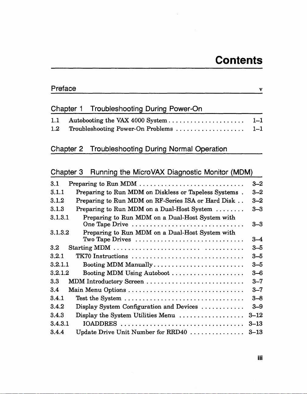
Contents
Preface v
Chapter 1 Troubleshooting During Power-On
1.1 Autobooting
1.2 Troubleshooting Power-On
the
VAX
4000
System.
Problems.
. . . . . . . . . . . . . . . . . . . .
. . . . . . . . . . . . . . . . . .
Chapter 2 Troubleshooting During Normal Operation
Chapter 3 Running the MicroVAX Diagnostic Monitor (MDM)
3.1
3.1.1
3.1.2
3.1.3
3.1.3.1
3.1.3.2
3.2
3.2.1 TK70
3.2.1.1 Booting MDM
3.2.1.2 Booting MDM Using
3.3 MDM
3.4
3.4.1 Test
3.4.2 Display
3.4.3 Display
3.4.3.1
3.4.4
Preparing
Preparing
Preparing
Preparing
Preparing
One Tape Drive
Preparing
Two
Tape
Starting
Main
Update
MDM . . . . . . . . . . . . . . . . . . . . . .
Instructions
Introductory
Menu
the
IOADDRES.
to
Run
to
Run
to
Run
to
Run
to
to
Drives
Options.
System.
System
the
System
Drive
MDM . . . . . . . . . . . . . . .
MDM on Diskless
MDM
MDM on a Dual-Host
Run
Run
Manually.
Screen.
Configuration
. . . . . . . . . . . . . . . . . . . . . . . . . . . . . . .
Unit
on
RF-Series ISA
MDM on a Dual-Host
...............................
MDM on a Dual-Host
..............................
...............................
. . . . . . . . . . . . . . . . . . . . . .
Autoboot.
. . . . . . . . . . . . . . . . . . . . . . . . . .
. . . . . . . . . . . . . . . . . . . . . . . .
. . . . . . . . . . . . . . . . . . . . . . . . . . . . . .
Utilities
Number
for RRD40 . . . . . . . . . . . . .
. . . . . . . . . . . . . . . . .
and
Devices.
Menu
..
. . . . . . . . . . . .
or
Tapeless
or
Hard
System.
System
System
..
...........
. . . . . . . . . . .
..................
Systems.
Disk..
. . . . .
with
with
..
. . . . .
..
..
..
..
..
..
1-1
1-1
3-2
3-2
3-2
3-3
3-3
3-4
3-5
3-5
3-5
3-6
3-7
3-7
3--8
3-9
3-12
3-13
3-13
iii
Page 5

3.4.5 Display
3.4.6 Select Single Device Tests
3.5
Exiting
the
Connect/Ignore
MDM . . . . . . . . . . . . . . . . . . . . . . . . . . . . . . . . . . .
Menu.
.........................
. . . . . . . . . . . . . . . .
..
..
3-13
3-14
3-16
Appendix A
Index
Figures
3-1
The
Main
3-2
Example
3-3
System
3-4
Sample
3-5
The
Single Device Tests
3-6
Example
3-7
Example
A-l
A-2
VAX
4000 Controls
VAX
4000 Controls
Tables
1-1
Troubleshooting Power-On
2-1
Troubleshooting Operation
VAX
4000 Controls and Indicators
Menu.
of
Configuration
System
of a Successful
of
. . . . . . . . . . . . . . . . . . . . . . . . . . . . . . . .
an
Unsuccessful
Utilities
an
Unsuccessful
and
and
Test.
. . . . . . . . . . . . . . . . . . . . .
and
Devices
Menu.
Menu
Test.
Indicators-Sheet
Indicators-Sheet
Problems.
Problems.
Screen.
. . . . . . . . . . . . . . . . . . . . .
. . . . . . . . . . . . . . . . . . . . . .
. . . . . . . . . . . . . . . . . . . . . .
Test.
. . . . . . . . . . . . . . . . . . .
..
. . . . . . . . . . . .
1 of 2 . . . . . . . .
2 of 2 . . . . . . . .
. . . . . . . . . . . . . . . . . .
. . . . . . . . . . . . . . . .
..
..
..
..
..
..
..
..
3-7
3-9
3-10
3-13
3-14
3-15
3-15
A-2
A-3
1-2
2-1
Iv
Page 6

Preface
Troubleshooting is
your
system. When
use
the
information
Using
recommended
This
•
•
•
• Appendix A contains a
The
possible problems
all
Digital service representative.
NOTE:
definitions
the
diagram
manual
Chapter
corrective actions.
Chapter
of
Chapter
diagnostic tool you
particular
a
indicators.
troubleshooting techniques described
problems.
2 describes problems you
your system
You
will find a Glossary
and
the
process
your
system
in
this
guide to diagnose
in
Appendix
in
this
guide.
contains
1 describes problems you
3 describes
If
three
chapters:
and
corrective actions.
the
can
use
problem.
diagram
with
your system,
the
actions suggested do not solve
acronyms.
of
isolating
does
not
A,
follow
may
MicroVAX.
to
test
your
showing
nor
in
the Operation
and
diagnosing problems
operate
may
in
do
as
described
the
problem.
the
troubleshooting procedures
experience
have
during
Diagnostic Monitor (MDM), a
system periodically
the
location
this
manual
the
actions suggested
the
manual
in
Operation,
at
power-on
normal
of
the
do
problem, call your
to
operation
or
controls
not
identify all
help
with
to isolate
remedy
with
and
and
word
v
Page 7

Conventions
The
following conventions
are
used
in
this
book:
Convention
BOLD
NOTE
CAUfION
WARNING
Meaning
A symbol
For
keypad. !
keypad.
A symbol
Ckey.
This
»>
This line shows
prompt.
Provides
Provides
Provides
denoting a terminal
example, !
bold
BOOT
Break!
Return!
indicating
type
indicates
MOAO
general
information
information
indicates
indicates
that
user
that
the
information
to
prevent
to
prevent
that
you
user
key
that
you
hold
input.
about
used
you
press
press
down
For
must
type
the
damage
personal
in
text
the
the
Return
the
Ctrl
example:
BOOT
current
to
equipment
injury.
and
Break
key
topic.
examples
key
on
key
on
while
MUAO
or
software.
in
your
your
you
at
this
terminal
terminal
press
the
book.
the
console
vi
Page 8

Chapter 1
Troubleshooting During Power-On
When
self-tests
if
to autoboot system software.
1.1
The
specified drive
device name) from console mode.
specified device
entering
If
automatically
you power on your system,
and
the
Break
start-up
EnablelDisable switch
routines. After successful completion
Autobooting the
VAX.
you
4000 system
when
each
the
Set
Boot command again.
have
not
from
attempts
you
time
entered
the
Ethernet
have
it
is
the
the
VAX.
is
set
VAX
4000 System
to boot
entered
powered on
the
The
Set
Boot command,
port,
EZAO.
processor performs a series of
to disable,
automatically
Set
Boot command (SET BOOT
system continues to boot from
until
the
(autoboot) from a
you specify differently
the
1.2 Troubleshooting Power-On Problems
If
you do
refer
If
the
representative.
NOTE: Table
tool
instructions on using MDM.
not
observe
to
the
descriptions
actions listed do
1-1
to
help diagnose problems. Refer
the
correct power-on
of
problems
not
solve
occasionally recommends
and
corrective actions
the
problem, call
to
and
boot sequence responses,
your
that
you
run
MDM
Chapter 3
of
of
the
self-tests,
system
this
attempts
system
in
Digital service
manual
boots
Table
as a service
the
by
1-1.
for
Troubleshooting During Power-On 1-1
Page 9

Table
Problem
1-1:
Troubleshooting Power-On Problems
Possible
Cause
Corrective
Action
Problems
No response
power
switch
on
(AC
is
not
Present
DC
OK
system
Present
but
nothing
the
console
Present
lit).
tor
AC
lit,
The
(AC
lit),
on
During
when
is
turned
indica-
indicator
is
not
lit.
has
power
indicator
displays
terminal.
Self-Tests
the
is
is
System
in.
No
outlet.
Circuit
is
tripped
Power
installed.
Power
failure.
Console
off.
Console
is
power
breaker(s)
the
power switch)
(is
in
cable
supply
terminal
terminal
not
plugged
at
the
(which
position 0).
is
incorrectly
or module
is
turned
is
wall
has
off
line.
Console
is
Console
up
correctly.
Baud
system
do
Power-On Mode switch
on
set
Terminal
terminal
incorrectly installed.
terminal
has
not
rate
setting
and
not
match.
the
console module
to
T.
is
been
of
the
terminal
defective.
cable
set-
done
the
is
Set
the
power
system.
Use
a different
circuit
breaker
wall outlet.
Set
the
the
circuit breaker{s)
your
Digital service
Set
the
the
cable
Set
the
your
Call
tive.
Turn
on
Put
the
to
the
instructions.
Make
properly
Reread
Terminal,
Set
the
the
system.
setting
Set
the
arrow).
Turn
off
to
see
if
fails self-tests, call
representative.
switch
Set
the
wall
controlling power
power
switch
power
switch
is
fully
power
switch
Digital
the
console
terminal
terminal
sure
the
at
both
the
section,
in
your
terminal
The
is
9600.
switch
to
terminal
it
passes
power
ends.
to
O.
Plug
switch
outlet,
or
check
to
position
trips
again,
representative.
to
O.
in
to
1.
terminal.
on
line.
is
Install
Check
the
representa-
the
seated
service
documentation
cable
Installation
baud
rate
normal
Run
and
its
your
to
operating
(indicated
turn
it
self-tests.
Digital service
in
the
to
1.
the
to
the
1.
If
call
that
socket.
Refer
for
installed
Console
manual.
match
by
an
on
again
If
it
1-2
VAX
4000 Troubleshooting and
DiagnostiCS
Page 10

Table 1-1 (Cont.): Troubleshooting Power-On Problems
Problem
The
system
(AC
Present
indicators
nothing
the
The
OK
displayed
terminal.
the
plays
The
an
ror
the
The
Menu
General
The
the
four
Instead
starting,
on
results
displayed
terminal.
The
RETRY"
on
the
are
is
displayed
console
terminal.
system
has
is
lit),
but
on
The
console module dis-
an E or
self-tests
error
message
summary
console
terminal.
Language
does
not
Problems
system
BOOT
prompt
minutes.
of
automatically
system
in
on
message
is
displayed
console
has
power Problem
and
DC OK
lit),
power (DC
nothing
the
console
LED
F.
halted
or er-
displays
Selection
appear.
returns
after
power-
> > >
being
the
console
"154 No bootable
terminal.
Possible
but
on
Problem
is
on
The
and
error
on
self-tests.
The
sole
from
the
The
port
character
During
twice found.
to
Boot
Sanity
on
the
Break
switch
The
mode.
Cause
with
CPU.
with
CPU.
system
detected
while
running
baud
rate
terminal
the
system.
terminal
the
system
on
is
different console
baud
does
multi-national
set
(MeS).
Sequence
timer
is
DESQA module.
EnablelDisable
is
set
to
is
in
media
an
its
the
con-
rate
on
not
sup-
enabled
enable.
console
was
Corrective
Call
your
tive.
Call
your
tive.
the
Copy
tion
mark
mary
and
resentative.
Check
set
to 9600.
Obtain a terminal
Disable
Action
Digital service
Digital service
number
in
call your Digital service rep-
that
terminal
sanity
the
the
following
error
baud
and
that
timer.
message
on
Refer
Option Installation Guide.
To
autoboot,
Disable
module) to disable (down).
system
located
If
you
console mode,
(»>BOOT
See
actions
sections
are
you
set
switch
by
pressing
on
the
System
prefer
to
use
device-name).
listed
of
this
using.
the
Break
(located
the
boot
the
in
table
for
Restart
Control
manually
BOOT
the
representa-
representa-
the
rate
the
system
supports
to
DESQA
Enable!
on
the
Reset
command
subsequent
the
boot
ques-
or
sum-
on
the
MCS.
console
the
button,
Panel.
from
device
is
Troubleshooting During Power-On
1-3
Page 11

Table 1-1 (Cont.): Troubleshooting Power-On Problems
Problem
The
countdown does
continue from 2
0, even
though
EnablelDisable switch
set
to
disable.
Problems
The
countdown
from 2 through
ever,
the
nal
displays
tem
error
The countdown
from 2
through
ever,
the
nal
displays console
ror
messages.
The
countdown does
continue from 2
0, even
though
Enable!Disable
set
to disable.
The
Fault
or
begins to flash.
Problems
System
does
countdown does
tinue
from 2
from
another
wrong software
on
the
console terminal).
through
the
Break
Booting
continues
0,
console
termi-
operating
messages.
continues
0, how- no bootable
console
termi-
through
the
Break
switch
indicator
Booting
not
boot
not
to
0)
or
device
is
displayed
Possible
not
The
system
system
software from either a disk
drive,
is
from
how- protected.
sys- orange).
er-
not
is
is
lit
from a Tape
(the
con-
boots
(the
or
an
RF-Series
The
system
Protect
button
The
system
ware.
The
system
line. (The Ready
is
in
the
problem
A
the
controller or ISA.
Cartridge
No
tape
tape
drive.
Cause
cannot
drive, a
the
Ethernet.
Integrated
disk
The
Write-
is
disk
system
disk
in
position.)
exists
cartridge
load
tape
is
write-
in
(glows
contains
soft-
is
off'
button
with
in
the
Corrective
See
actions
sections
you
are
Storage
Push
in
button
sure
you know
button
Install
Press
the
the
system
Press
Action
listed
of
this
table
using.
Assembly
and
release
to
the
out
corresponds
system
software.
appropriate
disk
the
RestartlRun
SCPo
If
the
Fault
your
system
Run
the
in
Chapter
remains
representative.
Insert a cartridge
software
MDM
3.
lit,
into
indicator
may
software
If
call
the
in
the
for
(lSA)
the
(unlit) position.
which
to
the
Ready
to
the
have
corrected itself.
the
Fault
your
containing
tape
drive.
subsequent
the
boot device
Write-Protect
Make
Write-Protect
system
disk.
button
out
button
stops
as
Digital service
on
position.
on
the
flashing,
described
indicator
system
1-4
VAX
4000 Troubleshooting and Diagnostics
Page 12
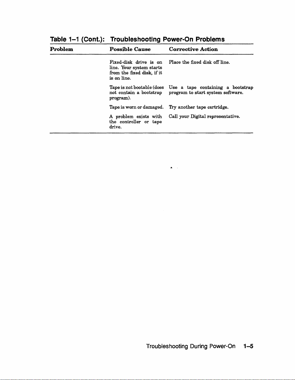
Table
1-1
Problem
(Cont.): Troubleshooting Power-On Problems
Possible
Cause
Corrective
Action
Fixed-disk
line.
from
is
on
Tape
not
program).
Tape
A
problem
the
drive.
drive
Your
system
the
fixed disk,
line.
is
not
bootable
contain a bootstrap
is
worn
or
exists
controller
is
on
starts
if
it
(does
damaged.
with
or
tape
Place
the
fixed disk off line.
Use a tape
program
Try
Call
to
another
your
Digital
containing a bootstrap
start
system
software.
tape
cartridge.
representative.
Troubleshooting
During
Power-On
1-5
Page 13

Page 14

Chapter 2
Troubleshooting During Normal
Operation
Problems
that
from a defect
procedures.
2-1
Table
the
actions listed do
lists problems, possible causes,
representative.
Table
Problem
System
The
(the
nothing
console
LED
module
F.
System
ing
Present
lit.
2-1:
Problems
system
DC
OK
displays on
terminal.
on
the
displays
loses power
operation.
indicator
has
is
lit),
an E or
The
occur
in
during
the
normal
operation of
your
system, from faulty settings,
and
corrective actions.
not
solve
the
problem, call
your
Troubleshooting Operation Problems
power
but
the
The
console
dur-
AC
is
not
Possible
Problem
The
into
No
outlet. circuit
Power
Power
installed.
with
system
the
wall outlet.
power
switch
cable
Cause
CPU.
is
not
plugged
at
the
has
tripped.
is
incorrectly
wall
Corrective
Call
your
tive.
Set
system.
Use
wall
Set
trips
representative.
Set
the
Set
Digital
the
power switch to
Set
the
a different
breaker
outlet.
the
power switch
again,
the
power switch
cable
is
the
fully
power
call
system
or
may
from incorrect
Digital service
Action
service
O.
power
switch
wall
outlet,
controlling
to
your
Digital
to
O.
seated
to
in
1.
switch
result
representa-
Plug
in
to
1.
or
check
power
to
1.
If
service
Check
the
socket.
If
the
the
the
it
that
Troubleshooting During Normal Operation 2-1
Page 15

Table 2-1 (Cont.): Troubleshooting Operation Problems
Problem
System
loses
ing
operation,
is
not
lit.
System
loses
ing
operation,
switch
is
The
Over
Condition
lit,
system
during
operation.
System
loses
ing
operation.
Failure
indicator
System
edly
during
eration.
prompt>
on
the
console
System
suddenly
RF
-Series
ISA
write
is
displayed.
power
the
DC
power
the
off (position 0).
halts
The
> >
power
Temperature
indicator
loses
power
power
The
is
unexpectnormal
console mode
is
displayed
terminal.
reboots.
Integrated
error
message
dur-
OK
dur-
is
dur-
Fan
lit.
op-
Storage
Possible
The
failed.
The
also
circuit
tripped.
The
ically
vent
One
failed.
The
on
the
was
The
the
pressed
The console
momentarily
or
disconnected.
The
was
Cause
power
supply
power
switch,
acts
as
breaker,
system
is
shut
down
overheating.
of
the
two
I Break 1
key
console
pressed
inadvertently.
Hold
Screen
console
terminal
inadvertently.
terminal
Run/Ready
pressed
inadvertently.
Assembly
ISA
is
(Wri teglows orange).
write-protected.
Protect
the
system
has
automat-
fans
or
terminal
turned
button
button
has
which
to
pre-
has
CtrllP
key
was
was
(lSA)
Corrective
Check
OK
Turn off
Digital
To
switch
seconds.
1).
Digital
Make
system
sure
the
Preparation.
Wait five
on.
Digital
Call
tive.
Type "c"
prevent
EnablelDisable
on
module
the
system.
causes
off
Let
prevent
the
ital
this
Problems
Press
(not
Action
the
DC
indicates a power
reset
If
switch
sure
the
guidelines
OK
your
service
to
service
is
system
representative.
the
circuit
off (position 0). Wait
Set
switch
trips
representative.
vents
are
not
near a heat
room
temperature
in
Tum
minutes,
If
switch
trips
service
representative.
your
Digital
and
recurrences,
to
Run/Ready
the
rebooting
recurrences,
RestartlRun
service
service.
and
lit).
press
switch
disable (position
button
Note
that
system
run
button.
representative
release
Write-Protect
light(s).
supply
breaker,
to
off
again,
clear;
the
VAX
power
then
off
again,
service
set
on
pressing
to reboot.
to
completion.
you
An
unlit
problem.
and
call
turn
on
(position
call
make
source;
is
4000 Site
switch
turn
call
representa-
I Return
I.
the
the
0)
and
to
restart
can
Call
your
to
(
\
DC
your
power
30
your
sure
make
within
to off.
switch
your
To
Break
console
press
the
Restart
To
disable
Dig-
perform
button
2-2
VAX
4000 Troubleshooting
and
Diagnostics
Page 16

Table 2-1 (Cont.): Troubleshooting Operation Problems
Problem
The
Fault
or
begins
ISA
read
is
displayed.
TK70
Tape
Green
light
after
you
Orange,
lights
blink
Handle
does
Handle
does
Cartridge
load.
TK70
passes
self-test
work.
indicator
to flash.
error
Drive
blinks
insert
yellow,
in
not
not
does
but
message
rapidly
the
and
unison.
move.
lock.
not
power-on
does
Possible
is
lit
A problem
the
ISA
cause
ton
Problems
Tape
tape.
defective.
green
A problem
Power-on
progress.
Tape drive
Cartridge
properly.
un-
Unload
working properly.
The controller
not
bad,
between
the
loose.
Cause
controller
is
not
spun-up
the
RunlReady
is
in
the
cartridge
with
test
is
is
button
or
the
the
controller
exists
with
or
ISA.
in
position.
leader
the
drive.
is
still
active.
not
inserted
is
may
connection
drive
and
may
Corrective
If
Fault
system
the
MDM software
Chapter
your
Digital service
be-
Press
but-
position.
light
comes on,
use.
is
Pull
the
cartridge.
Press
orange
the
yellow
is
unloading.
comes
remove
lights
the
Unload
cleared. Do
cartridge.
representative.
in
If
you
wait
for
go off
and
steadily.
Do
not
while
the
Reinsert
problem
service
not
Try
unloading
software command. Refer
system
be
Call
your
tive.
be
Action
indicator
may
have
3.
If
the
Ready
When
handle
Use
the
Unload
and
green
light
on
and
the
tape
continue
button,
Call
are
trying
the
orange
the
green
Then
attempt
yellow
the
tape
persists,
representative.
software
Digital
stops
corrected itself.
as
Fault
remains
representative.
button
the
green
the
ISA
is
open
and
another
to
not
try
cartridge.
button
lights
blinks,
When
the
you
hear
cartridge.
blink
after
the
try
to
your
Digital service
to
insert a cartridge,
and
yellow
light
again.
to
move
light
is
cartridge.
call
the
cartridge
manuals.
service
flashing,
described
lit,
to
the
indicator
available
remove
once.
go
out
the
cartridge
green
the
If
all
you
fault
remove
lights
to
remain
the
handle
on.
your
Digital
with
to
representa-
Run
If
and
light
beep,
three
press
is
If
your
the
in
call
out
for
the
the
not
the
to
on
the
a
Troubleshooting During Normal Operation
2-3
Page 17

Page 18

Chapter 3
Running the MicroVAX Diagnostic
Monitor
The
MicroVAX Diagnostic Monitor (MDM) is a software package containing
tests
diagnostic
system. MDM also
test
how devices
your
system
operating
CAUTION:
instructions
manager before
You
generally
• Before you
•
When
system
•
When
components
How the MOM Tests Work
MDM
limited
• MDM performs
customer
destroy
you receive
tests
diagnostics:
designed to isolate
permits
work
together.
on a
tape
cartridge
begin
If
your system is connected
halting
run
install
you
want
are
individual
tests
data.
the system to load MDM.
MDM
in
system
an
to
test
operating
internal
reads
do
not
you
in
three
software on a
error
your
from
write
and
identify faults
to display
The
(labeled MV DIAG CUST
Section 3.2.
situations:
message
system
correctly
devices
each
drive
to
the
your
system configuration
diagnostic
to
or
experience a problem
periodically to
in
your
and
drives
tests
a cluster, notify
new
system
system, however,
checks
as
writing
in
are
each
to
(MOM)
your
VAX
packaged
TKSO).
your
ensure
it
controller.
the
drives could
4000
and
with
MDM
cluster
with
your
that
performs
The
all
NOTE:
MDM
will test a tape drive or diskette drive only when the media
(tape or diskette) is inserted
• MDM checks only devices
peripheral
• MDM does
tests, which
devices
not
and
the
check
each
are
described below.
Running the MicroVAX Diagnostic Monitor (MOM) 3-1
in
the drive.
and
system.
device
not
the
as
thoroughly
connections
as
the
or
lines between
service diagnostic
Page 19

If
devices
a Digital service
pass
the
customer
representative
tests
but
you still experience problems, contact
for
further
testing. (
Customers
MicroVAX
maintenance
that
NOTE: Only qualified service personnel should use the service diagnostic
requiring
Maintenance
guide
you receive
more complete diagnostic
Kit.
The
maintenance
and
the
service diagnostic
with
your
system
is a
subset
testing
kit
tests.
of
the
should
includes
service version.
purchase
the
The
MDM version
the
system
tests.
3.1
Preparing to
Running
Read
Read
Integrated
MDM on a dual-host system.
3.1.1
MDM on
Section 3.1.1
Section 3.1.2
Storage Assembly (lSA). Read Section 3.1.3
Preparing to Run MDM on Diskless or Tapeless
certain
if
you
if
you
Run
plan
MOM
systems requires additional or special procedures.
to
run
plan
MDM on a diskless
to
install
MDM on a
or
tapeless system.
hard
disk
if
you
or
RF-series
plan
to
run
Systems
If
you
have
a diskless
network
Diagnostics Kit.
MV DIAG
Refer to
this
refer
(LAN), you
ENET
the
Micro VAX Diagnostic Monitor Ethernet Server User's Guide
time. Once you
again
to
this
Run
CUST.
or
must
MDM
have
manual
tapeless
obtain
the
using
the
installed
for specific
system
Micro
diagnostics
and
instructions
that
is
part
of
a local
VAX
Ethernet
in
down-line loaded MDM software,
on
Server
the
kit
running
that
MDM.
area
Customer
is labeled
at
NOTE:
area network (LAN), you cannot run MDM.
If
you have a diskless or tapeless system that is not part
7b diagnose problems, call a
of
a local
Digital service representative.
3.1.2 Preparing
MDM software
the
MDM
the
the
by
Guide for
NOTE: The MDM Hard Disk Kit is required for dual-host systems where
Hard
completion
customer. See
the
to
can
be
Disk Kit.
of
the
licensing
Run MDM on RF-Series ISA or Hard Disk
installed
"Diagnostic Software
the
requirements
on
an
RF
Installation
-series ISA
of
the
Installation
MDM
or
hard-disk
Hard
Disk
Acknowledgment"
drive using
Kit
requires
MicroVAX Diagnostic Monitor Hard Disk User's
and
installation
instructions.
one host is a tapeless system.
3-2
VAX 4000 Troubleshooting and Diagnostics
Page 20

3.1.3 Preparing
In
a dual-host configuration, two
their
ISAs
through
system
a
can
shared
directly access
common
to
Run
a Digital
system
disk.
MOM
Storage
any
of
on
systems
System
the
ISAs
a Dual-Host System
in
the
same
VAXcluster
Interconnect
in
either
system;
(DSSI)
this
can
bus.
include
share
Each
Before
be properly configured (systems ordered
configured
be
Diagnostics
for
system (no
instructions
tape
diagnostics
3.1.3.1 Preparing
To
you
Installation
according to
running
in
place.
running
drive. Use
Drive
run
MDM on dual-host systems
must
MDM diagnostics on a
at
the
factory)
must
be performed
diagnostics differs
tape
drive)
or
each
to
prepare
the
in
dual-host systems
use
the
MDM
Acknowledgment"
the
procedure
to
instructions
to
Run MOM on a Dual-Host System with One Tape
Hard
and
the
DSSI cable connecting
separately
depending
host
has
its
run
diagnostics
in
the
with a tape
with
Disk Kit. Complete
and
install
in
the
MicroVAX Diagnostic Monitor Hard Disk
User's Guide.
When
diagnostics:
1.
2.
the
installation
If
software is
and
perform
manuals.
Set
the
Break
to
enable
press
Break.
is complete,
installed
system
Turn
off
both
EnablelDisable switch on
(up).
Turn
on
shutdown,
hosts.
on
both
hosts.
use
the
system,
as
dual-host
as
on
own
section
one
the
described
If
the
system, your
dual-host systems
for
each
whether
tape
drive. Use
in
a dual-host system
after
drive
in
tape
drive (one
the
the
kit
on
following procedure
warn
in
your
the
console module
hosts
are
system
are
the
two
host.
The
one
host
is a tapeless
the
it
to
prepare
each
host.
tapeless
"Diagnostic Software
an
RF-series ISA
all
users
system software
of
already
powered-on,
must
properly
hosts
must
procedure
following
with
one
to
run
host)
to
run
the
to log off
each
host
Result:
»>
3. Use
BOOT/IOO DUAn (for K.FQSA-based DSSI),
of
Result:
Bootfile:
the
The
system
the
command BOOT/IOO DIAn (for KA670 CPU-based DSSI)
disk
containing
The
system
displays
prompts for
Running the MicroVAX Diagnostic Monitor (MOM)
the
the
console mode
MDM
the
Hard
Disk Kit.
bootfile:
prompt
where n is
on
the
your
unit
terminal.
or
number
3-3
Page 21

4.
Enter
the
systems
the
using
Run
the
name
of
the
file image: [SYSO.SYSEXE]MDMSHA.SYS for
with
on-board DSSI,
or
KFQSA storage adapter.
diagnostics
as
described
[SYSO.SYSEXE]MDM.SYS for systems
Press
I RETURN I to continue booting.
in
Section 3.2.
5. When you
the
Break
RestartlRun
and
the
host
using
diagnostics
have
completed
EnablelDisable switch
»>
button
prompt
the
as
on
that
is
displayed, boot
commands described
you did for
3.1.3.2 Preparing to Run MOM
Drives
Run
diagnostics on dual-host systems
following procedure:
NOTE:
You
can also use the MDM Hard Disk Kit as described in the
previous section.
1.
If
software
and
manuals.
2. Make
the
MDM diagnostics is
3.
Set
the
perform
sure
Break
is
installed
system
Turn
the
shutdown,
off
both
hosts.
Write-Protect switch on
in
EnablelDisable switch on
enable (up).
4.
Turn
on
both
hosts.
Result:
terminal.
indicating
The
normal
Mter
console mode.
power-on countdown
the
countdown, you should see
the
tests
on
the
is
set
to
enable
same host.
the
first host.
on
a Dual-Host System with
on
the
as
When
the
in
with
two
system,
described
diagnostics from
steps 2 and
tape
warn
the
the
write-protect position.
both
should
first host,
(up)
the
countdown completes
3,
and
and
Two
make
press
the
run
Tape
second
drives according to
all
users
in
your
tape
cartridge containing
to log off
system software
hosts' console modules
appear
the
on
the
»>
console
prompt
sure
the
the
the
to
5.
Insert
drive
command BOOT
the
6.
Run
7.
When
cartridge
RestartlRun
and
drive
3-4
the
tape
cartridge containing
in
one
host
and
lock
it
into
MOAO
to
tell
your
tape
cartridge.
the
diagnostics
you
have
by following
button
the
»>
prompt
in
the
second
VAX 4000 Troubleshooting and Diagnostics
as
described
completed
the
on
that
is
displayed,
host
and
the
procedure described
same
lock
place.
system
in
Section 3.2.
tests
on
host.
insert
it
into
the
MDM software into
On
the
same
to load
the
When
the
place.
the
MDM software from
first
host, remove
in
Operation.
the
countdown completes
tape
cartridge into
Enter
the
host,
enter
Press
the
command BOOT
the
the
tape
the
tape
the
tape
Page 22

MOAO
to boot
host.
the
tape
3.2 Starting MOM
You
must
start
the
diagnostic
are
booting MOM from a
booting MDM from
Diagnostic Monitor
an
RF-series ISA fixed-disk drive,
Hard
and
run
the
diagnostics
tests
differently for different media.
tape
cartridge,
read
Disk User's Guide.
as
you did for
Section 3.2.1.
refer
to
the
the
first
If
you
If
you
are
MicroVAX
NOTE: Unless instructed to
do
so,
do not change
any
settings or manipulate
devices while the tests are running. The diagnostic software interprets
change
3.2.1
Before you
in
the
CAUTION: Make sure the tape cartridge is write-protected.
The
VMS
software
following sections explain how to boot MOM
Follow
NOTE:
to
Micro
install
MDM
network facilities. When
a host system, the time required
3.2.1.1
NOTE: Before booting
users
of
state
as
an
error.
TK70
your
TK70
diagnostics
or
the
If
reduce the time required
Instructions
run
the
MOM software, be
Operation
tape
VAXELN,
or
use
directions carefully for
your system is
manual
drive.
run
has
the
autoboot
the
same
been
part
sure
you
understand
(contained
way
loaded.
feature
of
to
load MDM on each system by obtaining the
in
this
documentation kit) for
whether
You
to
setting
or
not
can
manually
automatically
manually
switches.
a local area network
VAX Ethernet Server Customer Diagnostics Kit. The
MDM
software on a host
to
other systems
Booting
to
log
off
and
that
MDM
MOM
Manually
MDM
perform system shutdown, as described
VMS
operating system
are
part
of
the LAN, using the DE Cne t / Ethernet
is down-line loaded
to
load
MDM
is
reduced significantly.
on a system with software installed, warn all
the
instructions
system software,
boot
the
diagnostic
boot
the
software.
and
automatically.
(LAN),
to
you
may
kit
enables
and
down-line load
target systems from
in
your system
such
you
software manuals.
any
using
as
The
want
to
1.
Make
sure
protect position.
the
Write-Protect switch
Running the MicroVAX Diagnostic Monitor (MOM)
on
the
tape
cartridge
is
in
the
write-
3-5
Page 23

2.
If
your
and
system
RF
-series ISAs.
contains system software, write-protect all
disk
drives
3. Move
4.
5.
6. Use
3.2.1.2 Booting
NOTE: Before booting
users
the
Break
(position 1).
Press
the
Restart
if
the
system
When
a TK70
cartridge
into
the
tape
containing
place.
Result: While you
normal power-on countdown should
After
the
countdown, you should see
mode.
the
command BOOT
software from
minutes. A yellow indicator
occurs.
completed.
to
Section 3.3 describes
log
off
EnablelDisable switch on
button
is
off.
green
light
drive, orange
the
MOM
Using Autoboot
and
perform system shutdown, as described
if
the
on
the
the
MDM software
are
inserting
MUAO
tape
cartridge. Loading
light
MDM
on a system with software installed, warn all
software manuals.
1.
Make
sure
the
Write-Protect switch
protect
position.
the
system
tape
and
is
running
drive glows steadily (if
yellow
to tell
on
the
lights
into
and
loading
appear
the
»>
your
the
tape
display you see
on
the
tape
console module to
or
tum
on
you
go out),
the
the
on
prompt
system
the
software
drive flashes while loading
insert
tape
drive
tape
cartridge,
the
console
indicating console
to load
takes
when
in
cartridge
is
enable
the
system
are
using
the
tape
and
lock
the
terminal.
the
MDM
several
loading is
your system
in
the
write-
it
2. Remove
series
3. Write-protect all
4.
Turn
5.
Move
(position 0).
6.
Turn
7.
When
cartridge
in
3-6
VAX
any
removable disks
ISAs off line.
off
your
system.
the
Break
on
your
system.
the
green
containing
place.
4000 Troubleshooting and Diagnostics
and
place
disk
drives
EnablelDisable switch on
light
on
the
and
RF
-series ISAs.
the
tape
drive glows steadily,
MDM software
all
fixed-disk drives
the
console module to
into
the
tape
insert
drive
and
the
and
RF-
disable
tape
lock
it
Page 24

Result: While
on
the
terminal. Loading
indicator
light
the
on
system
the
tape
loads MDM,
the
software
the
power-on countdown
takes
several minutes. A yellow
drive flashes while loading occurs.
appears
Section 3.3 describes
NOTE:
When loading is completed, place all RF-series IBAs
the
display
IBAs are not on line, they cannot
3.3
MOM
When
Make
If
the
screen display.
continue. The
Main
MDM software
sure
the
date
correct
Menu.
Introductory Screen
is
the
and
date
current
time
and
time,
For
example,
Main
loaded,
date
are
correct,
Menu
and
using
enter
appears.
the
time
the
3.4 Main Menu Options
The
Main
Menu
provides six options,
option
Figure 3-1: The Main Menu
MAIN
Type
1 2 3 4 5 6 -
by
typing
MENU
Test
Display
Display
Display
Display
Select
the
number;
the
the
System
System
the
the
the
Single
number
System
Service
Connect/Ignore
Device
then
and
Configuration
Utilities
Menu
Tests
press
the
you
see when loading
be
tested completely.
is
completed.
MDM introductory screen
in
the
introductory display
press
1
Return
format
1 to continue.
shown
in
the
If
incorrect, type
MDM
1O-JAN-1990 02:30 and
Section 3.4 describes options on
as
shown
pressing
Release
and
Menu
Menu
RETURN
I
Return
Devices
key.
in
I.
Figure
nnn
>
3-1.
Version
on
line.
If
is
displayed.
are
correct.
introductory
press
I Return I to
Choose
xX.xx
the
the
an
NOTE:
xx.xx
Option 4, "Display
purchased
service diagnostics
The
MDM
in
the sample screens provided throughout this chapter.
release
the
the
MicroVAX
and
service personnel should
Running the MicroVAX Diagnostic Monitor (MDM)
and
version numbers are represented by
Service Menu," is available only
Maintenance
the
system
use
the
Micro
Kit.
The
maintenance
maintenance
VAX
Maintenance
guide.
Kit.
if
kit
Only
nnn
and
you
have
contains
qualified
3-7
Page 25

The
next
five sections describe
3.4.1
The
and
jeopardizing
Test the System
"Test
the
how
they
System" option
work together. You
data.
runs a general
the
remaining
can
run
options
test
the
of
the
test
on
the
devices
at
any
Main
in
the
time
Menu.
(
system
without
When
If
automatically
preparations
screen explaining
When
"Begin Device Tests."
As each device
NOTE:
the diagnostic test sees these options as the same device. A
DHQll
you select "Test
this
is
the
you
are
Because
appear the same
the
System,"
first MDM option you
loaded.
and
ready
passes
of
The
loading process
loading
the
are
testing
to begin
the
test,
complete, you
procedures
the
test,
it
is
the internal similarity
to
the diagnostic test. A generic device name,
the
diagnostics
have
then
press I Return
listed on
of
are
selected,
takes
are
prompted
appears.
I.
the
screen.
prepared
the
several
The
system displays
for testing.
diagnostics
minutes.
to
presslReturnl.
are
When
the
some communications options,
DHVll
and
A
DH-CXO, is listed for similar communications options. The last letter in
each device name differentiates among multiple devices
For example,
second,
If
a device fails
Each
failure
occurred,
and
report
example of
DH-CXOA indicates one communications option, DH-CXOB a
and
so forth.
the
test,
you receive a failure message.
message
and
the
it
to
an
unsuccessful
identifies
field-replaceable
your
Digital service
test.
the
device
unit
(FRU). Copy
representative.
being
tested,
of
when
the
failure
Figure
the same type.
the
failure
message
3-2
shows
an
3-8
VAX 4000 Troubleshooting and Diagnostics
Page 26

Figure 3-2: Example
BEGIN FUNCTIONAL TEST
Device
SGCA
If
All
your
devices
failure
A
The
Field
system
was
OPTION:
Replaceable
Ethernet
has
disabled,
serious problems,
of
an
detected
SGCA
controller
no
Unsuccessful Test
Result
FAILURE DETECTED
while
Ethernet
Unit
tests
controller
(FRU)
the
run.
testing
identified
following
the
message
is
the:
may
appear:
Report
When
When
These
If
At
From
button
releasing
you can choose one of
the
message to
a failure message occurs,
all devices
tests
the
tests
the
end
the
of
Main
located on
the
pass
take
about
pass, you receive a success message.
the
system
Menu
the
System
Halt
button
your
Digital service
the
first
four
minutes
test,
you
can
located on
the
other
the
part
and
press
either
Control
options.
testing
of
the
test
I Return I to
exit
Panel
the
System
representative.
stops.
test,
the
exerciser
how
the
devices work together.
return
MDM
(SCP),
to
by
pressing
or
by
the
pressing
Control
Main
3.4.2 Display System Configuration and Devices
The
''Display System Configuration
by
the
recognized
When
you select "Display
diagnostics
have
selected,
takes
several
are
you
When
sample
prompted to
you
system
press
diagnostic software.
are
prepared
the
diagnostics
minutes.
When
press
I Return I ,
the
configuration
for testing.
are
I Return
configuration is displayed.
and
and
Devices" screen identifies devices
System
Configuration
If
this
is
automatically loaded.
the
preparations
I.
devices screen.
and
the
first MDM option you
The
and
loading
Figure
tests
begin.
Menu.
the
Restart
and
then
Panel
(SCP),
Devices,"
the
loading process
are
complete,
3-3
shows a
or
Running the MicroVAX Diagnostic Monitor (MOM)
3-9
Page 27

Figure
3-3:
System
Configuration
and
Devices
Screen
MAIN
SYSTEM
CPUA
MEMA
PDIA
SGCA
PDIB
No
Press
MENU
CONFIGURATION
...
MicroVAX
KA670-AA
...
MicroVAX
32
Megabytes.
...
SHAC
SHAC
Ver.
Second
SGEC
...
SHAC
SHAC
Ver.
Dg
TKA
...
the
RETURN
MC=02
MS670
DSSI
3.6
RF71
RF71
DSSI
3.6
Diagnostic
AND
CPU
FW=2.6
memory
65536
...
32MB
Subsystem
Unit
Unit
Generation
Subsystem
key
to
DEVICES
system
Pages.
not
return
Up to two lines of information
the
name
of
the
indicate
hardware
Figure
3-3
device
the
revision level
and/or microcode.
is
at
revision 2 for microcode (MC=02).
and
of
memory
#0,
Dssi
#1,
Dssi
Ethernet
loaded.
are
provided for
gives a
the
device.
For
example,
module
to
brief
Release
Disk,
Disk,
Controller
the
previous
nnn
Online
Online
each
menu.
device. One
description, a second
The
revision level
the
KA670
Version
CPU
xx.xx
>
line
line
can
refer
described
lists
may
to
in
3-10 VAX 4000 Troubleshooting and Diagnostics
Page 28
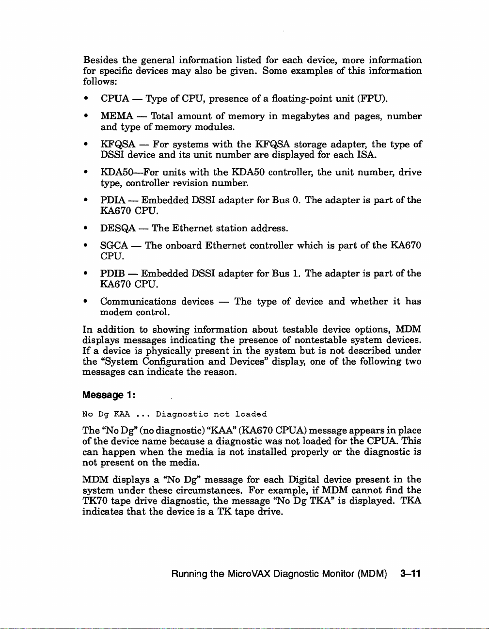
Besides
the
general
for specific devices
follows:
information
may
also
listed
be
given. Some examples of
for
each
device, more information
this
information
• CPUA - Type
•
MEMA - Total
and
type
• KFQSA DSSI device
•
KDA50-For
of
CPU, presence
amount
of memory modules.
For
systems
and
its
unit
units
with
type, controller revision number.
• PDIA - Embedded DSSI
KA670 CPU.
• DESQA
• SGCA -
The
The
onboard
Ethernet
Ethernet
CPU.
• PDIB
- Embedded DSSI
KA670 CPU.
•
Communications devices -
modem control.
In
addition
to showing information
displays messages indicating
If
a device is physically
the
"System Configuration
can
messages
indicate
present
the
reason.
and
of
a floating-point
of
memory
with
the
number
the
KDA50 controller,
adapter
station
in
megabytes
KFQSA storage adapter,
are
displayed for
for
Bus
O.
address.
controller which
adapter
the
for
Bus
The
type
about
presence of
in
the
system
1.
of
device
testable
nontestable
Devices" display, one of
unit
(FPU).
and
pages,
each
ISA.
the
unit
number, drive
The
The
adapter
is
adapter
and
part
whether
is
of
is
device options, MDM
system
but
is
not
described
the
following two
the
part
the
part
number
type
of
of
the
KA670
of
the
it
has
devices.
under
Message 1:
No Dg
The
of
can
not
MDM displays a "No
system
TK70
indicates
KAA
...
Diagnostic
not
loaded
''No Dg" (no diagnostic) "KAA" (KA670 CPUA) message
the
device
happen
present
tape
name
because a diagnostic
when
the
on
the
media.
under
these
drive diagnostic,
that
the
device
media
Dg"
is
not
message
circumstances.
the
is a TK
Running
the
MicroVAX Diagnostic Monitor (MOM) 3-11
was
not
installed
properly
for each Digital device
For
example,
message
tape
''No
drive.
Dg
loaded for
or
if
MDM
TKA"
is
appears
the
the
present
cannot
in
place
CPUA. This
diagnostic is
in
the
find
the
displayed. TKA
Page 29

Message 2:
Unknown
The
recognizable to MDM
appears
• A device
• A Digital device
...
Diagnostic
not
loaded
''Unknown'' (unknown device) message indicates
has
been
This
under
is
may
occur
attached
the
following circumstances:
configured to a
that
if
a device
nonstandard
has
no diagnostic
not
supported
to
the
CSR address.
has
been
on a VAX
attached.
• A non-Digital device
Once
all
devices
1
pressing
To
exit MDM, press I
Return
have
I.
Break
has
been
been
listed, you can
1
or
the
attached
Restart
to
return
button
the
3.4.3 Display the System Utilities Menu
Choose "Display
Menu.
If
available for your
When you select
is
the
first
loaded.
and
The
loading
the
System
system utilities
system
this
option,
MDM option you
loading process
are
complete, you
Utilities Menu" to display
in
addition to
configuration,
the
diagnostics
have
selected,
takes
several
are
prompted to
the
they
are
are
the
diagnostics
minutes.
that
a device
system.
attached
4000
The
to
the
system
system.
to
the
Main
Menu
on
the
SCPo
the
System
"IOADDRES" option
listed
on
the
menu.
prepared
press
When
I
Return
for testing.
are
automatically
the
preparations
I.
not
message
system.
has
been
by
Utilities
are
If
this
When you press IReturnl,
shows a sample
System
drives.
NOTE:
only one option,
3-12
If
your system does not have
IOADDRES, will
VAX 4000 Troubleshooting and Diagnostics
the
System
Utilities
Utilities
Menu
an
RRD40
be
available.
for a
Menu
appears.
system
/50
with
Optical Disk Subsystem,
Figure
two RRD40/50
3-4
Page 30

Figure 3-4: Sample System Utilities Menu
MAIN
MENU
SYSTEM
UTILITIES
Utility
1 - IOADDRES
2 3 -
selections
RRAA -Update
RRAB -Update
are:
drive
drive
unit
unit
number
number
for
for
RRD40
RRD40
controller
controller
A.
B.
Choose
pressing
the
option by typing
IRetuml.
the
option
number
listed
3.4.3.1 IOADDRES
NOTE: The c70ADDRES" option is intended for users
systems. This option is described
in
detail in the Industrial VAX
Troubleshooting manual.
The
"IOADDRES" option supplies a
Register
(CSR)
addresses
and
devices. The first available CSR
with a nonstandard
The
new
devices
options
in
added
address
your
system were configured properly
is
to your system
listing
interrupt
and
vectors
interrupt
also supplied.
are
configured properly
of
standard
that
MDM uses
vector for configuring devices
at
Digital service representative.
3.4.4 Update Drive Unit Number for RRD40
This
utility
compact-disk subsystem. Refer to
for
instructions.
allows you to
update
the
the
unit
RRD40
number
Disk Drive Owner's
3.4.5 Display the Connect/Ignore Menu
NOTE: The c'Connect / Ignore Menu" is intended for users
systems. The options
VAX Troubleshooting manual.
in
this
menu
are described
in
detail
on
the
of
Industrial
Control
the
factory.
in
the
for
the
of
Industrial
in
the Industrial
menu
and
in
field
RRD40
Manual
and
VAX
Status
testing
Any
by
a
VAX
The
"Connect/Ignore Menu" options allow you to customize MDM
can
load
your
diagnostics. You
well
as
load MDM diagnostics to a device
and
interrupt
vector.
own diagnostics to a
with a nonstandard
Running the MicroVAX Diagnostic Monitor (MOM)
particular
CSR
device,
address
3-13
as
Page 31

3.4.6 Select Single Device Tests
The
"Select Single Device Tests" option allows you to
test
of
the
device. A
performed
an
"exerciser test" to
during
device's individual circuits, called a "functional test,"
the
single device
ensure
that
the
tests.
device
The
functional
as
a whole
run
tests
for a single
test
is
followed
is
working properly.
(
is
by
When you select
diagnostics
have
selected,
takes
When
IReturnl. A screen
Figure
Figure
MAIN
SELECT SINGLE DEVICE TEST
Select
will
be
1 -
CPOA -MicroVAX
2 -
MEMA
3 -
PDIA -SHAC
4 -
SGCA -Second
5 -
PDIB -SHAC
6 - No Dg
Type
or
type 0 and
NOTE:
are
several
the
preparations
3-5
shows
3-5:
MENU
the
device
run
- MicroVAX
TKA -Diagnostic
the
number;
Because
th~
Single Device Tests from
prepared
the
diagnostics
for testing.
minutes.
and
loading
listing
The
followed
press
of
the
devices included
an
example of such a display.
Single
DSSI
DSSI
Device
number
by
CPO
memory
Subsystem
Generation
Subsystem
then
press
the
to
the
RETURN
the internal similarity
are
automatically loaded.
are
Tests
be
tested.
exercisers
system
Ethernet
not
loaded.
the
key
the diagnostic tests see these options
DHQll
DH-CXO, is listed for
each device
For example,
second,
appear the
name
same
to the diagnostic test. A generic device name,
similar
differentiates
communications options. The last letter
among
DH-CXOA indicates one communications option, DH-CXOB a
and
so forth.
the
Main
If
this
is
the
first
MDM option you
The
complete, you
in
are
prompted to
your
system is displayed.
Menu
Release
The
for 4 minutes.
Controller
RETURN
as
key,
to
return
of
some communications options,
the same device. A DHV11
multiple
nnn
functional
to
devices
the
of
Menu,
the
loading process
press
Version
tests
Main
Menu.
xx.xx
>
and
in
the
same
type.
Select a device for
IRetuml.
When you
testing
effect
3-14
press
begins.
is
displayed,
VAX 4000 Troubleshooting and Diagnostics
If
testing
I
Return
I,
the
the
device passes
and
the
by
typing
the
corresponding
system configures
the
exerciser
test
the
functional
begins.
The
number
and
pressing
device diagnostics
test, a message
exerciser
tests
to
run
and
that
for
Page 32
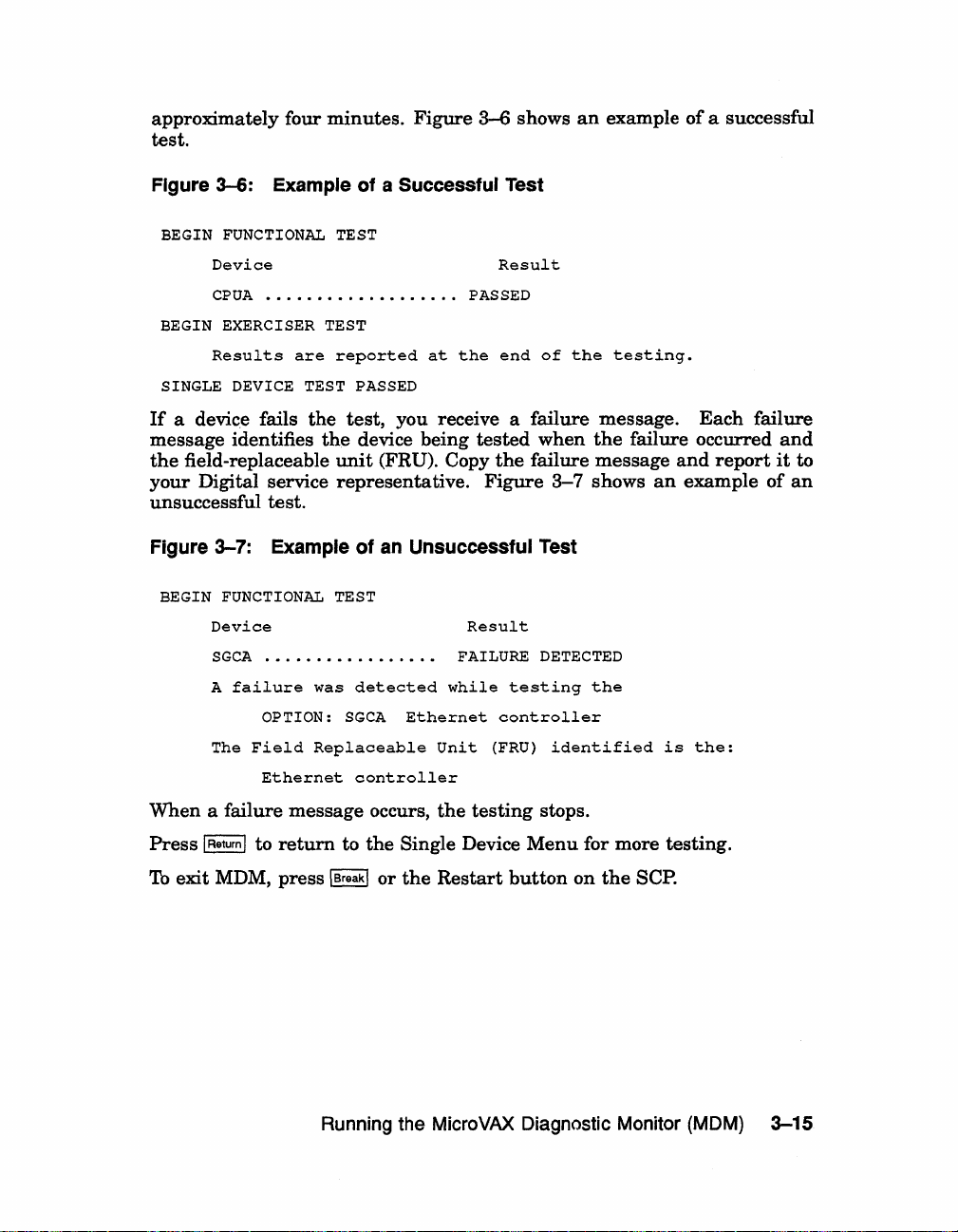
approximately four
test.
minutes.
Figure
3-6
shows
an
example
of
a successful
Figure
If
message identifies
the
your
3-6:
Example
BEGIN FUNCTIONAL TEST
Device
CPUA
...................
BEGIN EXERCISER TEST
Results
SINGLE DEVICE TEST PASSED
are
a device fails
field-replaceable
Digital service
of a Successful
reported
the
test,
the
device being
unit
(FRU). Copy
representative.
unsuccessful test.
Figure
BEGIN
3-7:
Example
FUNCTIONAL
Device
SGCA
.•...............
A
failure
OPTION:
The
Field
Ethernet
of
an
TEST
was
detected
SGCA
Replaceable
controller
Test
Result
PASSED
at
the
end
of
the
testing.
you receive a failure message.
tested
Unsuccessful
Result
FAILURE
while
Ethernet
Unit
when
the
failure message
Figure
3-7
Test
DETECTED
testing
controller
(FRU)
identified
the
failure occurred
shows
the
an
is
Each
and
report
example
the:
failure
and
it
to
of
an
When
a failure
Press
IReturnl
To
exit MDM, press \Break\
message
to
return
occurs,
to
the
or
Running the MicroVAX Diagnostic Monitor (MOM)
the
testing
Single Device
the
Restart
button
stops.
Menu
for more testing.
on
the
SCPO
3-15
Page 33

3.5 Exiting
Exit
MDM
by
doing one
•
Press
IBreakl.
•
Press
and
then
•
Press
the
Restart
MOM
release
button
of
the
following:
the
Halt
on
the
button
SCPo
on
the
SCPo
Remove
If
you
the
have
tape
run
software. Follow
Write-Protect
If
you
have
reboot
You
• At
your
can
the
button
run
system software.
reboot
console mode
where Dxxx
containing
disk drive
Use DIxx
the
system software
if
to disable (position
pressing
•
Set
the
sequence
the
the
Break
Restart
again
cartridge,
MDM on a new system, you
the
instructions
MDM on a system containing
your
system
is
the
your
system software.
or
an
this
IBreakl key.
as
explained
in
your
to write-enable
software
prompt
device
(»»,
name
and
in
one of two ways:
of
Use
RF-series ISA (with
is
an
RF-series ISA (with
is
0),
loaded,
to avoid
set
the
inadvertently
in
your
are
system
install
use
the
the
fixed
DUxx
the
Break
Operation
ready
to
install
software
system software.
system
software, you
command BOOT Dxxx,
disk
if
this
KFQSA storage adapter).
the
KA670 CPU).
EnablelDisable switch
halting
EnablelDisable switch to disable (position 0)
button.
This
causes
and
automatically load
your
system
system
to begin
software.
manual.
your
manuals.
or
RF
-series
is
an
the
system
the
system
Set
the
must
ISA
RA-series
Mter
by
and
press
power-on
3-16 VAX 4000 Troubleshooting and Diagnostics
Page 34

VAX 4000 Controls and Indicators
The
diagrams
4000 Model 300 system.
in
this
appendix
show
the
controls
and
indicators
Appendix A
on
the
VAX.
VAX 4000 Controls and Indicators A-1
Page 35

Figure A-1: VAX 4000 Controls and Indicators--Sheet 1 of 2
~
System Control
~
Panel
~
P
Over Temperature
Warning Indicator
y
!1
I
Power Supply
I~
o
/~
DC
OK
Indicator
--
Halt Button
--
Restart Button
Power Switch
AC Present Indicator
GJ~C
0D. Fan Failure
o~
~
o
gy,
~MO
I DC OK Indicator
Indicator
OVer Temperature
1\
1'1
\I
Condition Indicator
~powerBus
~
-'--~-
Connectors
Power Cable
Connector
MLO-004050
A-2 VAX 4000 Troubleshooting and Diagnostics
Page 36

Figure
ISA
A-2:
Controls
VAX
4000 Controls and
and
Indicators
Indicators-Sheet 2 of
2
Bus Node
ID Plug
Console
Power-On
Mode Switch
~:~:ctR;~tCh
LED Display
OSSI
Connectors I 0
Fault Indicator
Module
III
-~-
II
____
'1€S)
~:
I I
;=~D~
llJ
mr'
i
III
~/f'I
e~.
"'00
y
1°
0
'---
~ _ ~
~
,
II
~IIIII
I;
~
~
0
--
::
ModHied
Modular Jack
Break Enable!
Disable Switch
Bus Node
Eth.ernet Connector
SWitch
Standard Ethernet
Connector
10
Plugs
I
0
-
I
~
i
ThinWire Ethernet
Connector
I
MLO-004108
VAX
4000 Controls and Indicators
A-3
Page 37

Page 38
Index
A
Autobooting
the
c
Connect/lgnore
option
on
the
D
Diskless
Diskless
Display
Display
Dual-host
E
Error
Exiting
IOADDRES
or
tapeless
using
the
MicroVAX
Server
Diagnostics Kit,
or
Tapeless
running
option
option
running
all
No Dg,
Unknown,
option
MDM on,
System
Devices
on
Main
the
System
on
Main
systems
MDM on,
messages
devices disabled,
3-11
Micro
on
VAX
Main
Monitor (MDM),
VAX
system,
Main
Menu,
systems
Customer
Configuration
3-12
Ethernet
Systems
3-2
Menu,
Utilities
Menu,
3-3
3-9
Diagnostic
3-16
Menu,
3-2
3-9
3-12
3-13
1-1
3-13
and
Menu
M
Main Menu
of
Micro
VAX
(MDM),3-7
MDM
Hard
Micro
VAX
(MDM)
description,
medium
running,
starting,
when
to
Micro
VAX
Diagnostics Kit,
Diagnostic Monitor
Disk
Kit,
Diagnostic
3-1
containing,
3-1
3-5
run,
3-1
Ethernet
p
Power-on problems,
R
Rebooting
after
RF-series
booting from,
operation
the
running
integrated
elements
problems,
system
MDM,
1-4
s
Self-test
during
Single Device Tests
option
Starting
from a TK70
power-on,
on
the
Main
the
Micro
Monitor (MDM),
tape
3-2
Monitor
3-1
Server
3-2
1-1
storage
2-2
1-1
Menu,
VAX
Diagnostic
3-5
cartridge,
Customer
3-16
3-14
3-5
Index-1
Page 39

T
Tape drives
problems booting from a
Test
option
TK70
cartridge,
the
System
tape
on
drives
Main
1-4
Menu,
3-8
tape
operation
running
Troubleshooting
during
problems,
MDM on,
normal
u
Utilities
option
Menu
on
Main
2-3
3-5
operation,
Menu,
3-12
2-1
Index-2
Page 40
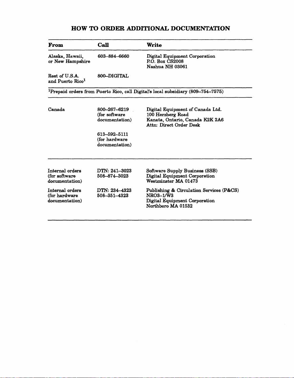
HOW TO
ORDER
ADDITIONAL DOCUMENTATION
From
Alaska,
or
Rest
and
IPrepaid
Canada
Internal
(for software
documentation)
Internal
(for
documentation)
Hawaii,
New
Hampshire
of
U.S.A.
Puerto
orders
orders
hardware
Rico
orders
Call
603-884-6660
800-DIGITAL
l
from Puerto Rico, call Digital's local
800-267-6219
(for software
documentation)
613-592-5111
(for
hardware
documentation)
DTN: 241-3023
508-874-3023
DTN: 234-4323
508-351-4323
Write
Digital
P.O. Box CS2008
Nashua
Digital
100
Herzberg
Kanata,
Attn:
Software
Digital
Westminster
Publishing
NR03-lJW3
Digital
Northboro MA 01532
Equipment
NH
subsidiary
Equipment
Ontario,
Direct
Supply
Equipment
& Circulation Services (P&CS)
Equipment
Corporation
03061
(809-754-7575)
of
Road
Canada
Order
Desk
Business
Corporation
MA 01473
Corporation
Canada
K2K 2A6
(SSB)
Ltd.
Page 41

Page 42

Reader's Comments
Your
comments
tation.
I
Accuracy (product
Completeness
Clarity
Organization
Figures
Examples
Index
Page
What
What
My
Please
rate
this
(easy
(useful)
(ability
layout
I like
I
lik~
additional
and
note
manual's:
(enough
to
understand)
(structure
(useful)
to
find topic)
(easy
to
best
about
least
about
comments
suggestions will
that
this
form
works
as
described)
information)
of
subject
find
information)
this
manual:
this
manual:
or
suggestions for
help
is
for
matter)
us
improve
comments
Excellent
the
quality
on
documentation
Good
0 0
0 0
0 0
0 0
0
0 0
0 0 0
0 0
improving
this
manual:
VAX 4000 Troubleshooting
of
and Diagnostics
EK-386AA-
our
future
only.
Fair
documen-
0
0
0
0
0
0
0
0
TS-001
Poor
0
0
0
0
0
0
0
0
I found
Page
Please
o
o
o
o
D
Name!I'itle
Oompany
Mailing
[0/87
the
following
Description
indicate
Administrative
Computer
EducatorlTrainer
Programmer/Analyst
Sales
Address
the
Operator
errors
type
Support
in
this
of
user/reader
manual:
that
you
most
nearly
o
ScientistlEngineer
o
Software
o
System
o
Other
Support
Manager
(please specify)
represent:
Dept.
Date
Phone
Page 43

Do Not
Tear
- Fold
Here
and
Tape
- - - - - - - - - - - - - - - - - - -
Do Not
Tear
- Fold
BUSINESS REPLY MAIL
FIRST CLASS PERMIT NO.33
WILL
POSTAGE
BE
DIGITAL EQUIPMENT CORPORATION
CORPORATE USER PUBLICATIONS
PK03-1/D30
129 PARKER STREET
MAYNARD, MA 01754-2198
11111
••
11
11111.1.1.1
Here
MAYNARD
PAID BY ADDRESSEE
••
11111.1
MASS.
••
1.1
••
111.1.1.1'1111.1
NO POSTAGE
NECESSARY
IF
MAILED
IN
THE
UNITED STATES
!
\
 Loading...