

Page 1

EK-OTU58-UG-004
TUS8
DECtape
II
User
Guide
Page 2
,
EK·OTU58·UG·004
TUS8
DECtape
User
II
Guide
Prepared
Digital Equipment Corporation
by
Educational Services
of
Page 3
Copyright () 1978, 1981, 1982. 1983
by Digital Equipment Corporation
All Rights Reserved
1st Edition, October 1978
2nd Edition, June 1981
3rd Edition, October 1982
4th Edition, December 1983
The reproduction
strictly prohibited. For copy information, contact the Educational Services Department. Digital Equipment Corporation, Maynard, Massachusetts 01754.
The information in this document
without notice. Digital Equipment Corporation assumes
responsibility for any errors that may appear
document.
This equipment generates, ml.($, and may emit radio
quency. The equipment has been type tested and found to
comply with the limits for a Class A computing device
pursuant to Subpart J
designed to provide reasonable protection against such
radio frequency interference. Operation
in a residential area may cause interference
the user
whatever measures may
.interference.
The following are trademarks
poration, Maynard, Massachusetts.
at
of
this material, in part or whole,
Printed in U.S.A.
of
Part
his own expense
be
is
subject to change
in
15
of
FCC rules, which are
of
this equipment
in
which
case
will
be required to take
required to correct the
of
Digital Equipment Cor-
is
no
this
fre~
DEC
DECUS
DIGITAL
RIIID
UNIBUS
DECtape
DECtape
II
DECnet
DECsystem-l0
DECSYSTEM-20
DECwriter
DIooL
EduSystem
VAX
MASSBUS
OMNIBUS
OS/8
PDT
RSTS
RSX
VMS
lAS
VT
Page 4
CHAPTER 1 INTRODUCTION
CONTENTS
1.1
1.2 General Description
1.3 Block Diagram
1.3.1 Drive Control
1.3.2 Processor. . . . . . . . . . . . . . . . . . . . . . . . . . . . . . . . . . . . . . . . . . . . . . . . . . . . . . .
Scope
...
"'
...
........
"'
......
..............................•..........•.......
..........................
...
, ,
...
" . "
......
" . . . . .
" "
......
" "
......
.. . .. . .......
" "
"'
..
"'
.........
" .
"'
........... " ..
. . . . . . . . . . . . . . . . . . . . . . . . . . .
.
........
,
.... " .......
,.
1-1
1-1
1-3
1-
1-3
1.4 Specifications. . . . . . . . . . . . . . . . . . . . . . . . . . . . . . . . . . . . . . . . . . . . . . . . . . • . . . 1-4
1.4.1 Performance . . . . . . . . . . . . . . . . . . . . . • . . . . . . . . . . . . . . . . . . . . . . . . . . . . . . . 1-4
1.4.2 Electrical
1.4.3
Mechanical"
1.4.4 Environmental
1.S
Configurations . . . . . . . . . . . . . . . . . . . . . . . . . . . . . . . . . . . . . . . . . . . . . . . . . . • . .
1.6 Hardware Documentation Ordering Information '
1.
7 Digital Repair Service
...........................................•...........
..........
.................
" .......
"'"."
""
.... " ..
".,,"'
"'"'."
. . . . . . . . . . . • . . • . . • . • . . • . . . . . . . . . . .
........
........•.......•.......................•.•...
"""
..
"'''''"."'
"
........
..
,,"'
, ,
"'.,,"'
........
""'.
'"
'
" 1-10
1-5
1-6
1-6
1-7
1-9
CHAPTER 2 OPERATION
2.1 TU58-DA,
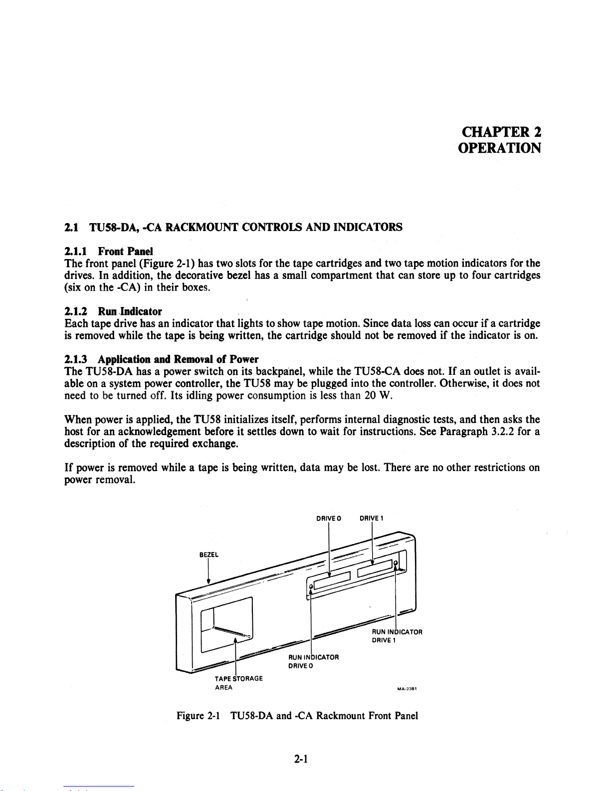
2.1.1
Front
2.1.2 Run
2.1.3 Application and Removal
2.2 TU58·EA,
2.2.1 Front
2.2.2
Run
2.2.3 Application and Removal
2.3
2.3.1
TU58-VA Controls and Indicators
Front
2.3.2 Run
2.3.3 Application and Removal
2.4
TU58 Components Controls and Indicators
2.4.1 Application and Removal
2.5
Cartridge
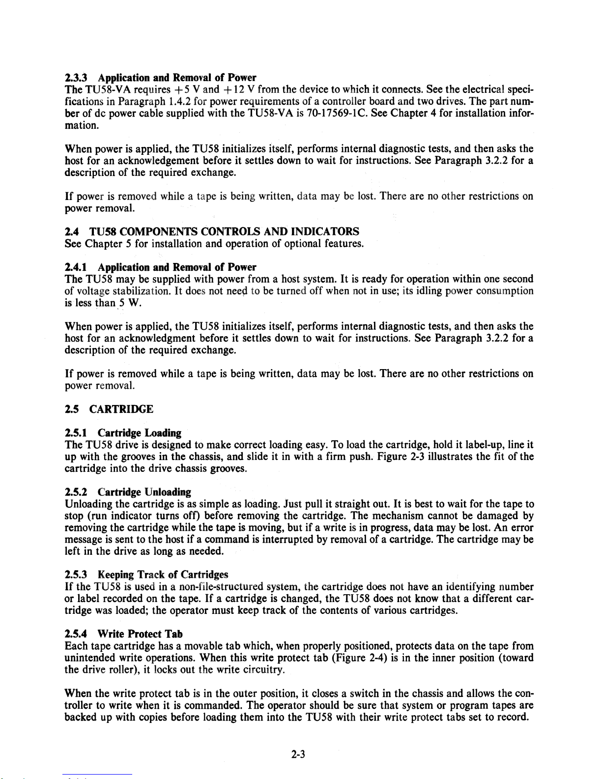
2.5.1 Cartridge Loading. . . . . . . . . . . . . . . . . . . • • . . . . . . . • • . . . . • • . . . . . . . . . . . . .
2.5.2 Cartridge Unloading • . . • . • . • • • • . . . . • . • • . . . . . . . • . . . . . . . . . . . . . . . . . . . .
2.5.3 Keeping Track
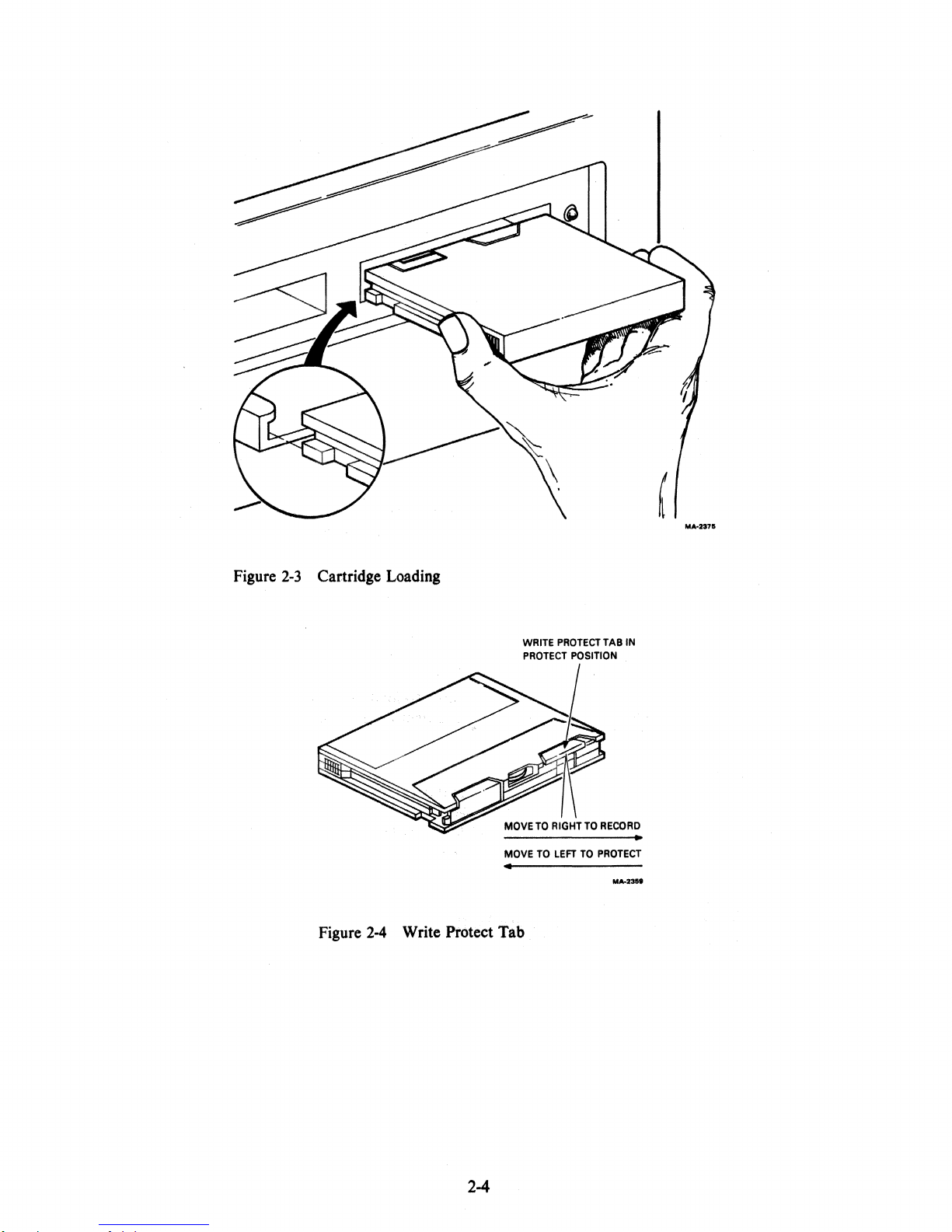
2.5.4 Write Protect
2.5.5 Cartridge Storage and Care . . . . . . . . . . . . . . . . . . . . . . . . . . . . . . . . . . . . . . . . . .
.Maintenance
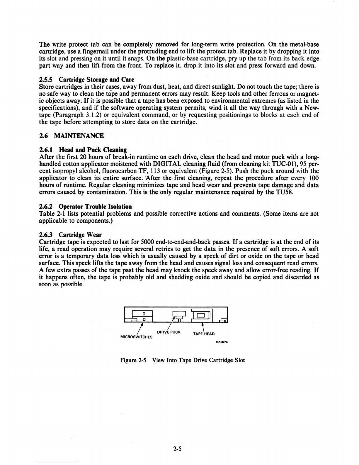
2.6.1 Head and Puck Cleaning. . . . . . . . . . . . . . . . . . . . . . . . . . . . . . . . . . . . . . . . . . . .
2.6.2 Operator Trouble Isolation. . . . . . . . . . . . . . . . . . . . . . . . . . . . . . . . . . . . . . . . . .
2.6.3 Cartridge Wear
-CA
Rackmount Controls and Indicators
Panel
.•..............................................•....
Indicator.
-EB
Controls and Indicators
Panel
".""""""1O"""""
Indicator"
Panel
Indicator.
•........................................•...........
.
it
it
it
'"
Tab.
.. , ,.
........•....•.....•....
. . . . . . . . . . . . . . . . . . . . . . . • . . . . . . . . . . . . . • . . • . . . . . . . . . .
of
Power
...................................
...........................•......
..
""
..
.,,,,,,,,,,,,,,,
" " " " " " " " " " " " " " " " " " "
of
Power
...................................
..
...
,,,,,,,,,,
'"
" " " " "
..
" • "
,.
..
" " " "
,.
" "
" " " " . " " " " " " " " " " " " " ... " " " " " " " " " "
..
~
...............•......•..•.••.....•.•.
• . . . . . . . . . . . . . . . . . . . . . . . . . . . . . . . • • . • . • • • • . . . . . . . . . . 2-2
of
Power
of
Power
•••••••
of
it
Ii
•
it
••••
Cartridges. . . • . . . . . . • . • . . . . . . . . . . . . . . . . . . . . . . . . . . . . 2-3
..•.......•.•..•..•................
...•.........
.........•.........................
it
•
Ii
it
•••••
it • it
••
it
••••
'
...•... , ........
"
it
it
••••
it
...
it
••
.
it • ,. • it
. . • . . . • . • . . . . . • . . . . . . . . . . . . . . . . . . . . . . . • . . • . • . . . .
.......
•..
,.
........
,.
•.....
,. , ............
, . , . , . . . . . . . . .
. . . . . . . . . . . . . . . . . . . . . . . . . . . . . . . . . . . . . . . . . . . . . . . .
2-1
2-1
2-1
2-1
2-2
2-2
2",,2
2-2
2-2
2-2
2-3
2-3
2-3
2-3
2-3
2-3
2-S
2-5
2-S
2-S
2-S
3
iii
Page 5
· CHAPTER 3 PROGRAMMING
3.1
3.1.1
3.1.2
3.2
3.2.1
3.2.1.1
3.2.2
3.2.3
3.2.3.1
3.2.3.2
3.2.4
3.2.4.1
3.2.4.2
3.2.5
3.3
3.4
General
Radial Serial Protocol (RSP) and Modified
Instruction Set
PASCAL
Principles
.......................•.............•.............
Block Number, Byte Count, and Drive Number
Special Handler Functions
Packets
Break
Command
.......
Packet
Usage
and
Initialization
Packets
Maintenance
" " " " " " "
""."""""
..
Mode
Special Address Mode
Data
Packets" " ..
" "
..
Radial Serial Protocol
Modified Radial Serial Protocol
End
Packets
..
" ... "
.... " ..
.. " .. " ....
" "
....•...••.•.••.•...........•.............
RSP
(MRSP)
..
" " " " " " "
"."""."
"""".,,,.,,,,,,,,"
... " ..
..
" " " " " " " " " " " " " " " " "
""""
..
""".".""""""".,.""
..
".""
....
""".,,,
...
,,.,,,,,,
...........•............•.•...................
...•.•.•..........•••.....•••...........•...
" " " ,
.. " ....
" " " "
.... " .. " ......
.......................••..•......•......•..
...........•......•...••...•..•.•.••
to
...... " ... " .....................
.. " ....
" ....... " ......... " . " ...
TU58 Handler Algorithm Definitions
............••.•..•......•
......•.•...••..•..•.
.. " ..
" , " "
...
... ,,.,,
..
,,
..
,,.,,,,,,,,,,,,,
..
,,
..
,,.,,,,,,,,,,,,,,,,.,,
" " " "
...
" " . "
.. " ....
" "
"
..
" "
... " .... " .... " .. " .......
.,
" ....... " ..... "
.. " .. " ....
..
" . " . " " " "
"".,."
..
".,
....
,,,,,,,,.
...
,,
....
,,,,,,.,, ...
....
" "
..
" " " . " ,
" • " "
" ........ " ... " "
...
..
CHAPTER4 INSTALLATION
4.1 Introduction"
4.2 Rack Installation
4.2.1
Rackrnount
4.2.2 Unpacking
4.2.3
Power
4.2.4 Removing Bottom Plates for Controller Board Configuration
..
" , " " " " " , " " , , " " " " " " " " , " " " " "
..
"""""""""""""""
..
"""
Selection
..
(-DA
Version) . . . . . . . . . . . • • • . • . . . • . . . . . • .
....
,,
111
, , " , , , "
..
"""""".""."
""
..
""""""""
•. " ..
..
"."""
""""""".""
..
".".".""""
" " " " " " " " " " " " " " "
..
, , , , " , " , " , , , , " , " , , , • " , " • ,
..
,,
...
,,",,
....
..
,,""",,.,,"""",,
............•.•
.. " ""
•.
,,"",,
" " " " " " "
•• . • . . • . . . .
...
,,""""""
..
,,"",,.,,"
4.2.5 Rackmounting Procedure. . . . . . . . . . • . • . . . • . • • • • • • • . • • • . • • . . . . • . . . • • •
4.3 Rack Installation
4.3.1 Rackmount """."
4.3.2 Power Selection for the Rack Version
4.3.3 Removing Module from Chassis. • • . • . • . .
4.3.4 Reinstalling the Module
4.4 Installation
4.4.1 Tabletop Installation
4.4.2
Solid Mounting Installation
4.5 Installation
4.5.1 Tabletop Installation
4.5.2
Solid Mounting Installation
4.5.3 Mounting the
4.6 Components" ... , " " " " " " " , " " " " " " " " " " " " " "
4.7 Interface Standards Selection and Setup
4.7.1 Selecting Interface
4.7.2 Connecting Standards Jumpers
4.8 Operational Checkout
4.8.1 Checkout
4.8.2 Configuring Interface Modules
4.8.3 Checkout
(-EA
(-VA
of
Interface
of
Drive
(-CA
Version) . . • . . . . . . . . . . . . . . • . . • . . • . . • • • . . . • . • • • • • .
.. " ..
""."""""""".""."."""""""""" ... ""."""
.....•.....•••••.••.••..•.••..•..
..
. • • • •• • • . . • . • • . .
..••..•.............••••.•.•••••.••••.•••.•.
and
-EB
Versions)
.....................................
.....••..•.............•.•••.....•.••.••..••.•
.........................................
Version)
.•••..•.•....•.••..•...•......•••.••••.••.•.
.•........•••.•••••••....•.••••..•.••........•
.......•.•.•...............•...•...•..••.
TU58-VA
to
the
SBll
(or BAll-VA)
......................
e."
....
" .. " " " " " .. " " " " " " " " • " "
...•••..•.•..•.....•..•..........
Standards..
• . • . . • •• • . • . • . . . . • • . . • .
...
• • . •
..•..•.•......•..•••..••..•.•.....•....
.....••••.•......•......•.••..•..........••••.•
•.•......•••••••.•..•••.••...•••...•....•....
•• • • . • . . . . . . . . . . . . • . • • . • • . • . . • • . . . . • .
Command Function
...••...........••....••........
....
",,
..
. . .
.. . •. . •.
... ,,,,.... 4-7
..
. •
•.
......
.. " 4-13
.•
"
..
3-1
3-1
3-1
3-1
3-1
3-2
3-3
3-3
3-4
3-4
3-4
3-4
3-4
3-5
3-6
3-11
4-1
4-1
4-1
4-1
4-1
4-2
4-2
4-7
4-8
4-10
4-10
4-12
4-12
4-12
4-13
4-13
4-13
4-13
4-16
4-17
4-19
4-19
4-19
4-21
4-31
iv
Page 6
CHAPTER S OPTIONS
5.1 Run Indicator. . . . . . . . . . . . . . . . . . . . . . . . . . . . . . . . . . . . . . . . . . . . . . . . . . . . . .
5.1.1 Installation . .
..
..
.. .. ..
..
.. .. .. .. .. .. ..
..
.. .. .. .. .. .. ..
..
.. .. .. ..
..
.. ..
..
.. .. ..
..
..
..
..
.. .. ..
..
.. ..
..
.. .. .. ..
..
5.2 Boot Switch.......................................... .....................................................................
5.2.1
5.2.2
S.2.3
General..............
................
Operation ......................................................
Installation~
.. . .. .. .. .. .. ..
.. .. . .. ..
..
..
..
.. .. .. . .. ..
..
..
.. ..
..........
e"
..................................
.. ..
.. ..
..
.. .. .. . ..
...........•.....
.. .. .. . .. ..
.. ..
if
................
.. .. ..
.. .. . .. ..
..
..
..
..
. . 5-2
5-1
5-1
5-2
5-2
-2
5
APPENDIX A TUS8/pDP-ll TOGGLE-IN BOOT
APPENDIX
APPENDIX
APPENDIX
APPENDIX
B RSP SEQUENCE
C SAMPLE DEVICE HANDLERS
D CARTRIDGE REPAIR
E FffiLD REPLACEABLE UNIT SPARES LIST
FIGURES
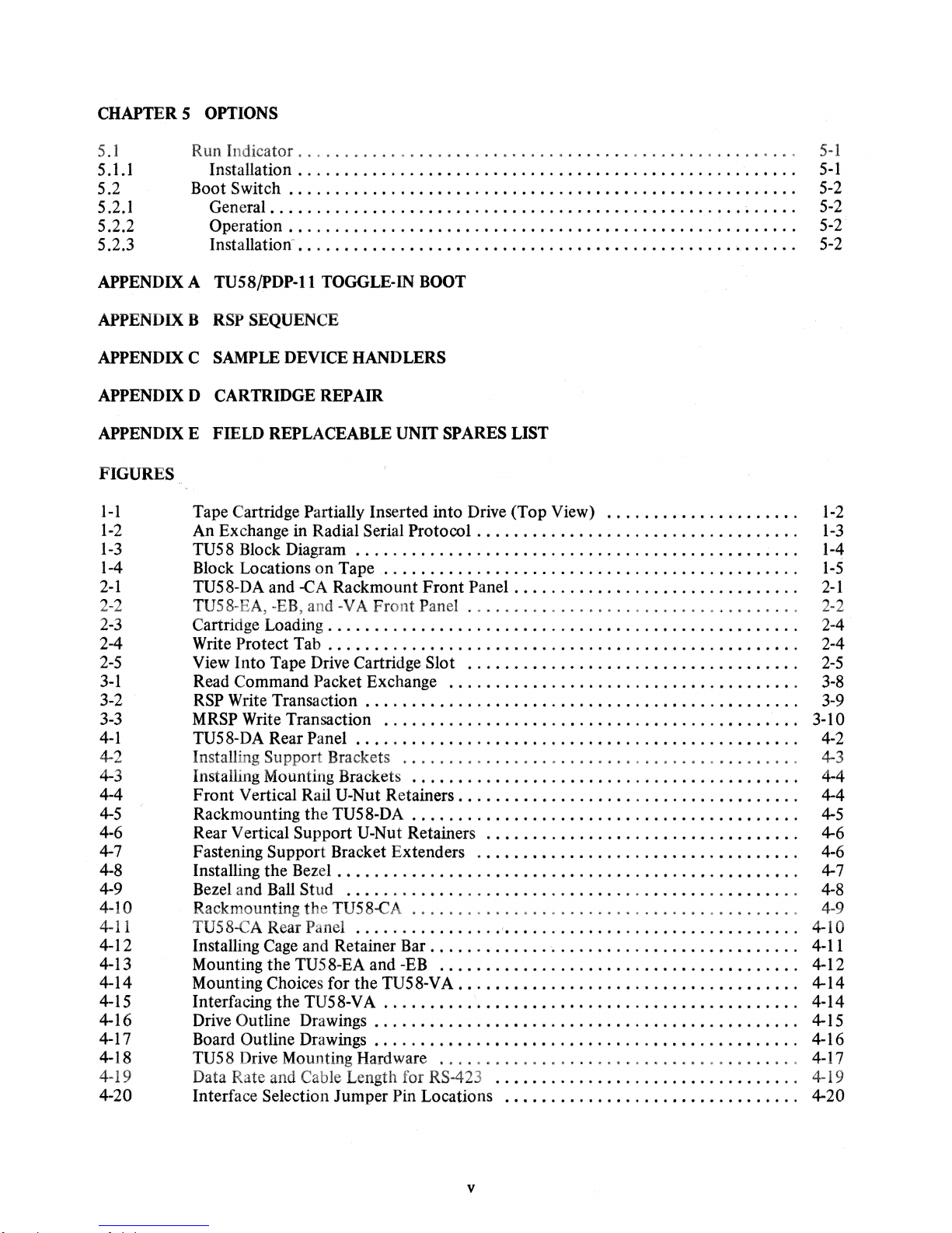
I-I Tape Cartridge Partially Inserted into Drive (Top View)
1-2
1-3
1-4
2-1
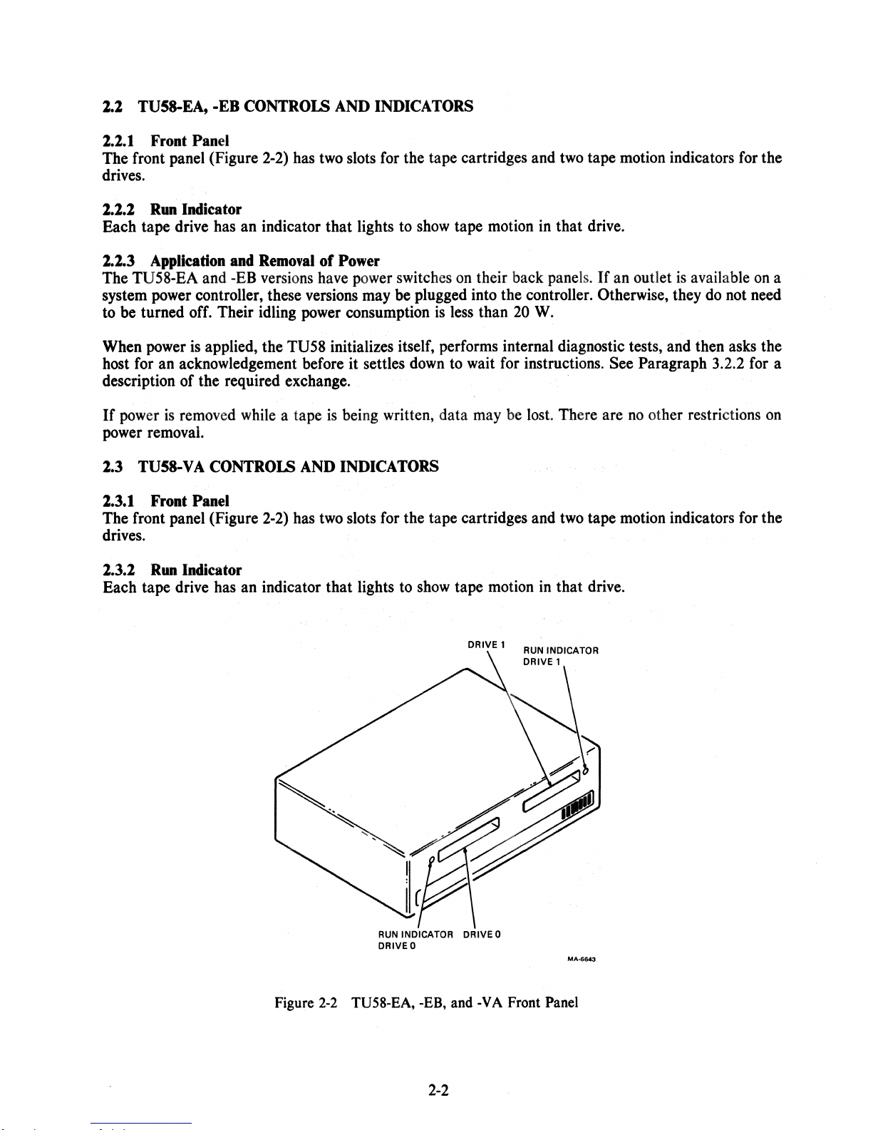
2-2 TU58-EA, -EB, and -VA
2-3
2-4 Write
2-5
3-1
An Exchange in Radial Serial
Protocol.
. . . . . . . . . . . . . . . . . . . . . . . . . . . . . . . . . .
TU58 Block Diagram .........................................................................................
Block Locations
TU58-DA and
on
Tape
...........•........................•..•.....
-CA
Rackmount Front
Front
Panel
Panel.
• • • . . . . . . . . . . . . . . . . . . . . . . . . . . .
.............
Cartridge Loading. . . . . . • • . . . . . . . . . . . . . . . . . . . . . . • . . . . . . . . . . . . . . . . . . . . 2-4
Protect Tab . . . . . . . . . . . . . . . . . . . . . . . . . . . . . . . . . . . . . . . . . . . . . . . . • . . 2-4
View Into Tape Drive Cartridge Slot
Read Command Packet Exchange
....................................
......................................
•.......•............
. . . . . . . . . . . . . . . . . . . . . . .
1-2
1-3
1-4
1-5
2-1
2-2
2-5
3-8
3-2 RSP Write Transaction . . . . . . . • . . . . . . . . . . . . . . . . . . . . . . • . . . . . . . . . . . . . . . . 3-9
3-3
4-1
4-2 Installing Support Brackets
4-3 Installing Mounting Brackets
MRSP
Write Transaction
TU58-DA Rear Panel
............................................•
................................................................................
..................................•...•....
••......•.......•.........................
3·10
4-2
4-3
4-4
4-4 Front Vertical Rail U-Nut Retainers. . . . . . . . . • . . . . . . . . . . . . . . . . . . • . • . . . . . . 4-4
4-5
4-6 Rear Vertical Support U-Nut Retainers
4-7 Fastening Support Bracket Extenders
4-8 Installing the Bezel .
4-9 Bezel and Ball Stud
4·10 Rackmounting the TU58-CA
4-11
4-12 Installing
4-13 Mounting the TU58-EA and
4-14 Mounting Choices for the
4-15 Interfacing the TU58-VA
4-16 Drive Outline Drawings . . .
4-17 Board
4-18
4-19 Data Rate and Cable Length for
4-20 Interface Selection Jumper Pin Locations
Rackmounting the TU58·DA . . . . . . . . . . . . . . . . . . . . . . . . . . . . . . . . . . . . • . . . . .
..•.....•..........•...•..........
...•......................•........
• . • . . • . . . . . . • . . . • . • • • . • • • . . . . . . . • . • .
....................
'"
. • . . • • . • . . . • . • . . • . • • • . . . • • . • . . . . 4-8
...
• • • • .
...
• • .
...
. . 4-7
..........................................
TU58-CA Rear Panel
Cage
and Retainer
Outline Drawings
TU58 Drive Mounting Hardware
................
Bar.
• . . . . . . . . . .
-EB
.......................................
TU58· V A . • . . . .
..•...••..
• . . . . . . . . . . . . . . . . . . . . . . . . . . . . . . . • . . . . . . . .
•.
• . . .
...
. . • • . . • . • • . • . . • • • • . • . • . • • . . • . . • . . • . . .
.......................................
RS-423
".
. . . . . . . . . . . . . • • . • . . . . . . . . . . . .
..
. . . . • . . . . . . . . . . . • • . . . . . .
..
. . .
.. .. . .. ..
'.
........•...•••...•...............
. . . .
..
............••.......•.•.........
. . . . .
..
..
.. . ...
..
..
..•...............•.............
4-5
4-6
4-6
4-9
4-10
4-11
4-12
4-14
4·14
4-15
4-16
4-17
4-19
4-20
v
Page 7
4-21
4-22
4-23 OLVII-J Factory Conftguration Summary
Factory
TUS8
Wiring
Wiring " .. " ....... " ....
(9600 Baud)
............................................
" . . . . . . . . . . . . . . . . . . . . . . . . . . . . . . . . . . ...
...............................
4-24 MXVII-A Jumper Locations. . . . . . . . . . . . . . . . . . . . . . . . . . . . . . . .
5-1
D-l
0·2
0·3
D-4
0-5
Installation
Baseplate
Threading the Metal·Base Cartridge
of
Run Indicator
Screw
Locations
..........•...•.
.......
. . . . . . . . . . . . . . . . . . . . . . . . . .
" " . " " " " " "
...
" . "
..
" "
.......
•.•...•.....•........................
Head Gate and Spring. . . • . • . . . . . . . . . . • . . . . . . . . . . . . . . . . . . . . . . . . . . . . .
Stretch the Belt with the Floating Roller . . . . . . . . • . . . . . . . . . . . . . . . . . . . • . . . . 0-3
Threading the Plastic-Base Cartridge. . . . . . . . . . . . . . . . . . . . . . . . . . . • . . . . . . .
TABLES
4-21
4-21
4-25
• . . . . . . .
..
4-26
5-1
" . " . " . " . . . . 0-1
0-2
..
0-3
..
D-4
2-1
3-1
3-2
3-3
34
4-1
Operator Trouble Isolation. . • . . • . . . . . . . • . . . . . . . . . . . . • . • . . . . . . . . . . . . • . . 2·6
Command Packet Structure
Data
Packets"
.... " ...
" "
...
.. " ..
"."""
....
" "
... " ...... " ...... " ............
End Packet . • • . . . . . . . . . • • • . • . • . . . . . . . . . . .
Instruction
TU58 Module Connections
Set
""
" . " . " . . " " . " . " "
.....•.............................•........
..
" . "
4·2 MXVII-A Standard Factory Conftguration
""
...... " ... " ... " ...
""
..
".".,,
"
..
. • • . . . . . • • . . • . . . • . . . . . • • . 3·5
...
" . " " . " " . " . . . " . " " " . . " . " " . . . " " "
...............................
..
41
" . . .
• 3-3
3-5
3-7
4-18
4-27
vi
Page 8
1.1
SCOPE
The
TU58
This
manual
specific
tem
manuals.)
DECtape
provides
information
II
is a low-cost,
information that a
about
using
the
mass-storage
user
needs
TU58
under
device
to
that
install,
may
be
interface,
DIGITAL operating
used
in a wide
and
systems,
CHAPTER 1
INTRODUCfION
variety of
operate the tape
refer
to
applications.
system.
the
individual
(For
sys-
Chapter 1
mechanical
Chapter 2
operator's
Chapter 3
trates
serial
programming
Chapter 4
operational
Chapter 5
Appendix A lists
provides a general
requirements.
contains
reference
is a programming
command
protocol
sequences,
(MRSP),
example
describes
checkout
describes
a PDP-II
Appendix B contains
Appendix C lists
assembly
language.
sample
Appendix 0 covers
description
of the TU58
The configurations
important information
section.
guide.
explains
lists
system
for a TU58
instructions
of
the tape
the
optional
toggle-in
an
RSP
sequence
device
cartridge repair
It
contains
the details of the radial
instruction
device
for
jumper
system.
features
bootstrap
to
handlers
procedures.
and a list
section
for
daily
describes
operation
functional
codes
and
handler.
selection;
available
for
in
the
mechanical,
the TU58.
exercise a new
written
in
POP-ll FORTRAN
descriptions
serial
byte
TU58.
cartridge.
of
its
specifications,
the
available
and
routine
protocol
sequences,
electrical,
variations
maintenance.
of the
TU58
(RSP)
and
includes a general
and
IV
and
including
electrical
of the TU58.
It
is
the
command
and
the
interface
installation;
set,
modified
PDP-ll MACRO-ll
and
system
illus-
radial
purpose
and
Appendix E lists
1.2 GENERAL DESCRIPTION
The TU58
cartridges
which
tracks. They
disks
or
DECtape,
mented
in
an
the
field
replaceable
is
a random-access, fixed-length-block, mass-storage tape
store
262
kilobytes of data
may
be
accessed
using a new,
operating system
units
(FRUs)
in
by
a program
high-level
by
setting aside several
in a fashion
instruction set. A file-oriented structure
in
the TU58.
5I2-byte
1-1
blocks.
similar
blocks
system.
There are
to
on
the tape
that
It
uses
preformatted tape
256
blocks
employed
to
store a directory.
for
on
each of
data stored
is
easily
two
on
imple-
Page 9
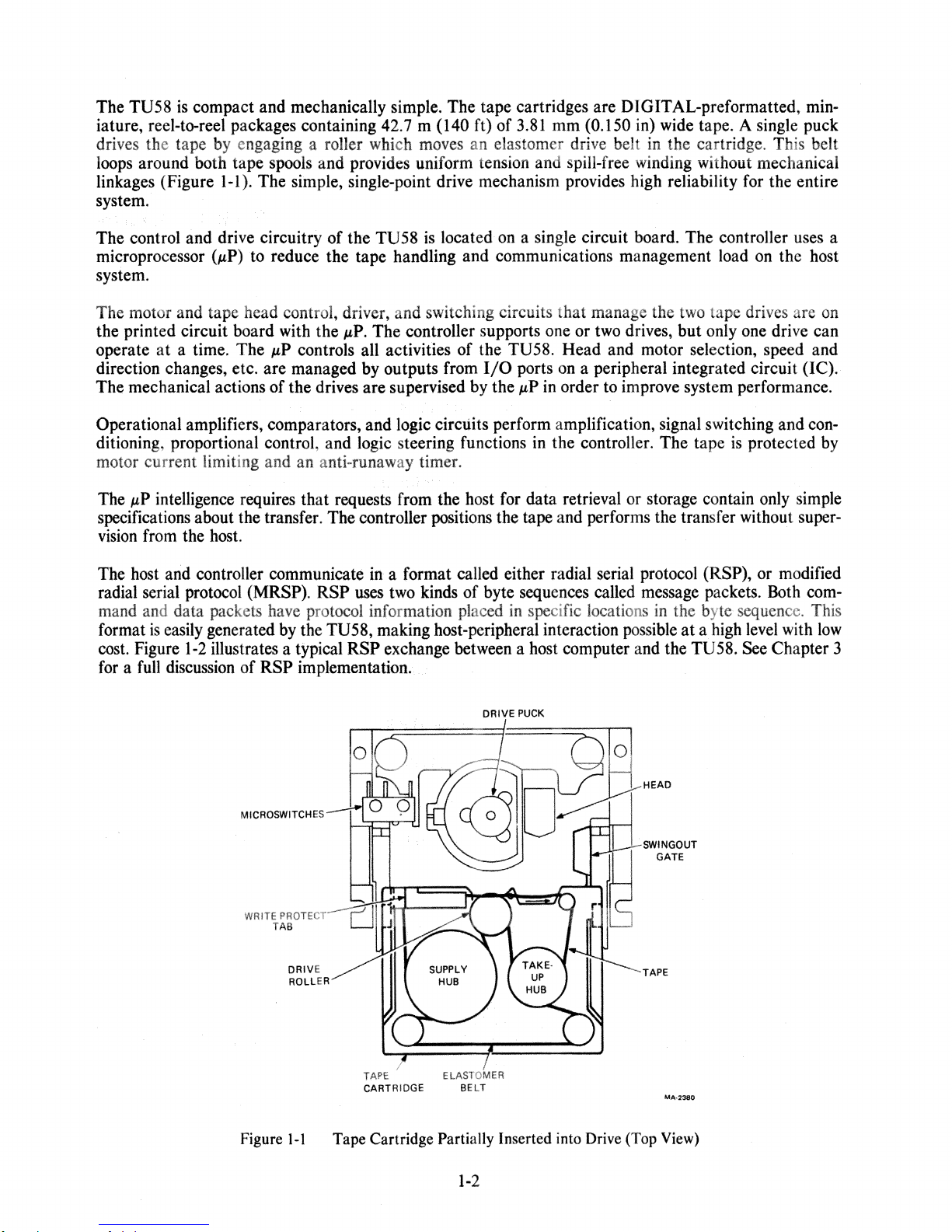
The TU58
iature, reel-to-reel packages containing 42.7 m (140 ft) of
is
compact and mechanically simple. The tape cartridges are DIGITAL-preformatted, min-
3.81
mm (0.150 in) wide tape. A single puck
drives the tape by engaging a roller which moves an elastomer drive belt in the cartridge. This belt
loops around both tape spools and provides uniform tension and spill-free winding without mechanical
linkages (Figure I-I). The simple, single-point drive mechanism provides high reliability for the entire
system.
The control and drive circuitry of the TU58
(p.P)
microprocessor
to reduce the tape handling and communications management load on the host
is
located
on
a single circuit board. The controller uses a
system.
The motor and tape head control, driver, and switching circuits that manage the two tape drives are
the printed circuit board with the
operate
a time. The
p.P
at
direction changes, etc. are managed by outputs from
The mechanical actions of the drives are supervised by the
p.P.
The controller supports one or two drives, but only one drive can
controls all activities of the TU58. Head and motor selection, speed and
I/O
ports on a peripheral integrated circuit (IC).
p.P
in order to improve system performance.
Operational amplifiers, comparators, and logic circuits perform amplification, signal switching and
ditioning, proportional control, and logic steering functions in the controller. The tape
is
protected by
on
con-
motor current limiting and an anti-runaway timer.
The
p.P
intelligence requires that requests from the host for data retrieval or storage contain only simple
specifications about the transfer. The controller positions the tape and performs the transfer without
vision
from the host.
The host and controller communicate in a format called either radial serial protocol
(RSP), or modified
super-
radial serial protocol (MRSP). RSP uses two kinds of byte sequences called message packets. Both command and data packets have protocol information placed in specific locations in the byte sequence. This
is
format
cost. Figure
easily generated by the TU58, making host-peripheral interaction possible
1-2
illustrates a typical RSP exchange between a host computer and the TU58. See Chapter 3
for a full discussion of
RSP implementation
..
at
a high level with
low
DRIVE
PUCK
HEAD
MICROSWITCHES
SWINGOUT
WRITE PROTECT
TAB
DRIVE TAPE
ROLLER
TAPE ELASTOMER
CARTRIDGE
BELT
Figure I-I Tape Cartridge Partially Inserted into Drive (Top
GATE
MA·2380
View)
1-2
Page 10
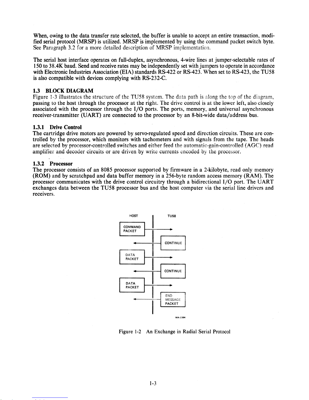
When, owing to the data transfer rate selected, the buffer
fied serial protocol (MRSP)
See
Paragraph 3.2 for a more detailed description of MRSP implementation.
is
utilized.
MRSP
is
implemented by using the command packet switch byte.
is
unable to accept an entire transaction, modi-
The serial host interface operates on full-duplex, asynchronous, 4-wire lines
150 to 38.4K baud. Send and receive rates may
with Electronic Industries Association (EIA) standards
is
also compatible with devices complying with R8-232-C.
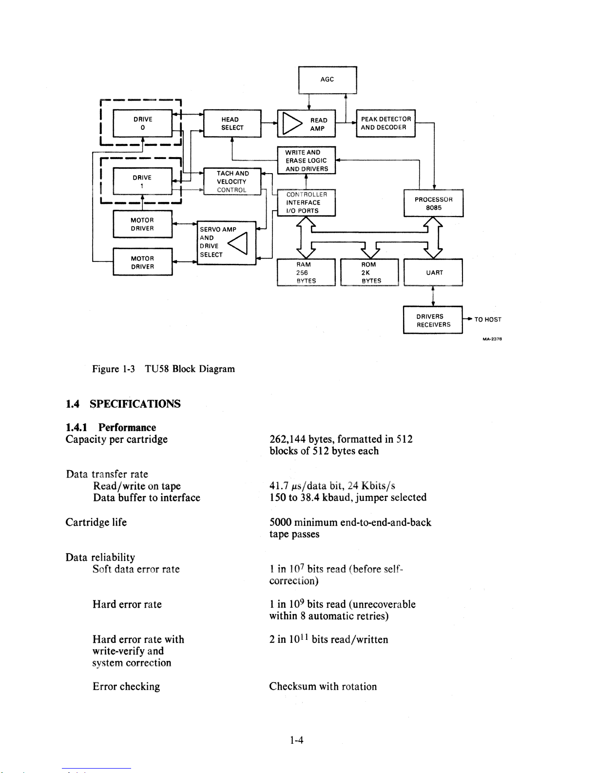
1.3
BLOCK
Figure
passing to the host through the processor
associated with the processor through the
receiver-transmitter
1.3.1
The cartridge drive motors are powered by servo-regulated speed and direction circuits. These are controlled by the processor, which monitors with tachometers and with signals from the tape. The heads
are selected by processor-controlled switches and either feed the automatic-gain-controlled
amplifier and decoder circuits or are driven by write currents encoded by the processor.
1.3.2 Processor
The processor consists
(ROM) and by scratchpad and
processor communicates with the drive control circuitry through a bidirectional
exchanges data between the TU58 processor bus and the host computer via the serial line drivers and
receivers.
1-3
Drive
DIAGRAM
illustrates the structure of the TU58 system. The data path is along the top of the diagram,
(UART) are connected to the processor by an 8·bit-wide data/address bus.
Control
of
an 8085 processor supported by firmware in a 2-kilobyte, read only memory
data
buffer memory in a 256-byte random access memory (RAM). The
be
independently set with jumpers to operate in accordance
R8-422 or RS-423. When set to R8-423, the TU58
at
the right. The drive control is
I/O
ports. The ports, memory, and universal asynchronous
at
jumper-selectable rates of
at
the lower left, also closely
(AGe)
I/O
port. The UART
read
HOST
I COMMAND
..
DATA
PACKET
..
DATA
PACKET
Figure
1-2
I
I
I
CONTINUE I
I
I
I
I
I
CONTI~UE
I
I
An Exchange
I
I
END
MESSAGE
PACKET
TU58
• PACKET
•
•
MA·2384
in
Radial Serial Protocol
1-3
Page 11
TO
HOST
Figure
1-3
TUS8
Block
1.4 SPEOFICATIONS
1.4.1
Performance
Capacity per cartridge
Data transfer rate
Read/write on tape
Data buffer to interface
Cartridge life
Data reliability
Soft data error rate
Hard error rate
Hard
error rate with
write-verify and
system correction
Diagram
262,144 bytes, formatted in 512
blocks of 512 bytes each
41.7
ps/data
bit,
24
Kbits/s
150 to 38.4 kbaud, jumper selected
5000 minimum end-to-end-and-back
tape passes
1 in
107 bits read (before self-
correction)
109 bits read (unrecoverable
1 in
within 8 automatic retries)
2 in
1011
bits read/written
Error checking
Checksum with rotation
1-4
Page 12
Average access
Maximmn
Read/write
Search
tape
time
access tirnc
tape
speed
speed
Bit density
Flux
reversal density
Recording method
9.3 seconds
28
seconds
76
cm/s
(30
152
cm/s
(60
315
bits/em
945
fr/cm
Ratio
encoding
in/s)
in/s)
(800
(2400
bits/in)
fr/in)
Medium
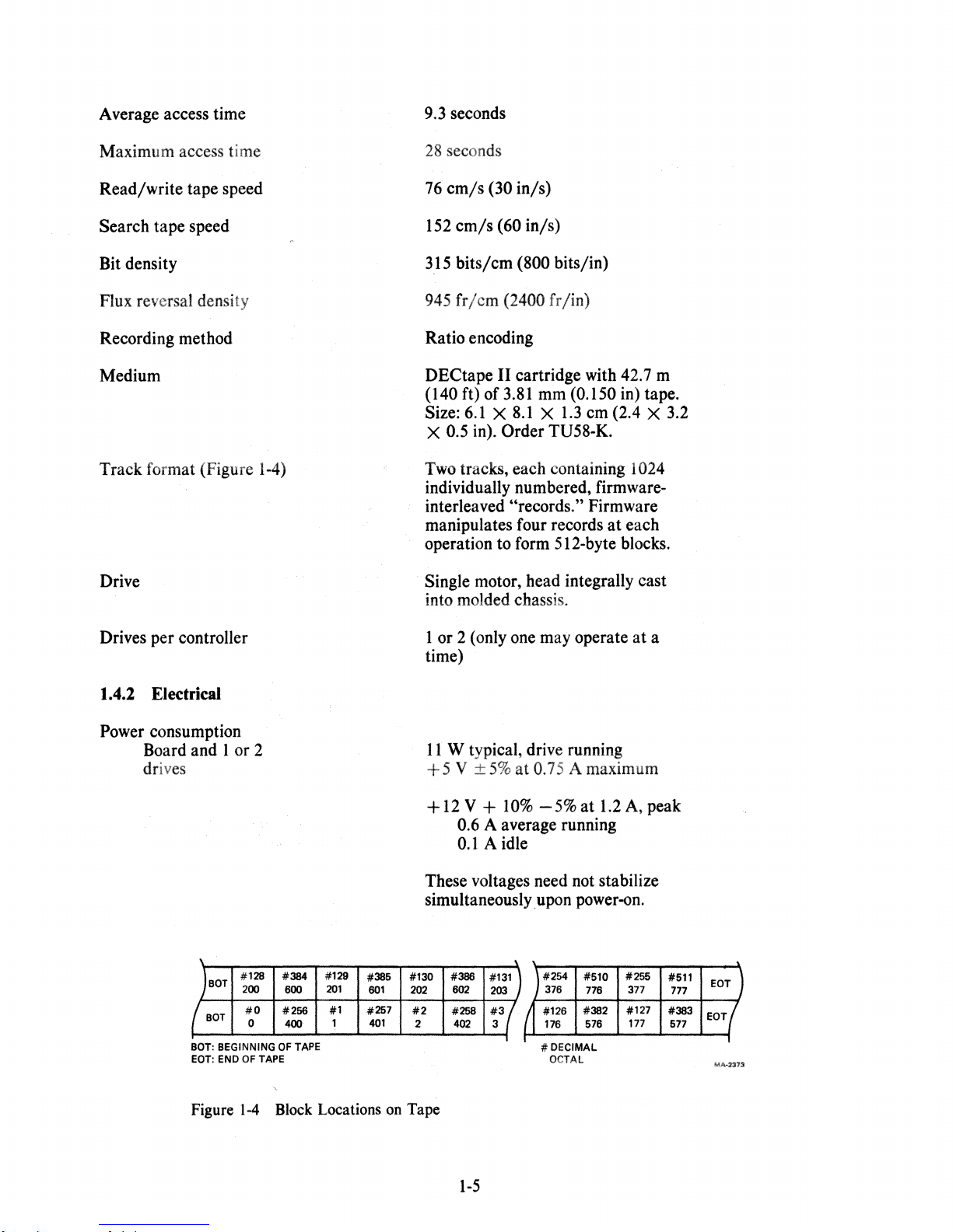
Track
format (Figure 1-4)
Drive
Drives
per
controller
1.4.2 Electrical
Power consumption
Board and
drives
1
or
2
DECtape
(140
Size: 6.1
X
0.5 in).
Two tracks,
II
ft)
of
3.81
X 8.1 X 1.3
Order
cartridge with 42.7 m
mm
(0.150 in) tape.
em
(2.4 X 3.2
TU58-K.
each
containing 1024
individually numbered, firmwareinterleaved
manipulates four records
operation
Single motor,
"records."
Firmware
at
to
form 512-byte blocks.
head
integrally cast
each
into molded chassis.
1
or
2 (only one may operate
at
a
time)
11
W typical, drive running
cor.
5 V
:t5%
at 0.75 A
+ 12 V + 10%
-5%
maximum
at
1.2
A,
peak
0.6 A average running
0.1 A idle
\
#128
JBOT
(
BOT
BOT:
BEGINNING
EDT:
END
Figure
#384
200
600
#0
#256
0
400
OF
OF
1-4
TAPE
TAPE
Block Locations on Tape
#129
201
#1
1
#385
601
#257
401
These voltages need not stabilize
simultaneously
#130 #386
602
202
#2
#256
2 402
upon
~lJ
~3(
#254
376
#126
176
#
DECIMAL
OCT.AL
power-on.
#510
776
#382
576
1-5
#255
377
#127
177
#511
777
#383
577
~1\~;a37""
Page 13
Rackmount
90-
128 Vac, 180 - 256 Vac,
47 -
63
Hz,
35
W maximum
Serial interface standards
1.4.3 Mechanical
Drive
Board
TU58-DA
TU58-CA
cabinet
TU58-EA, -EB, -VA
Power
board
rackmount
connector
to
In accordance with
RS-422 or RS-423;
compatible with RS-232-C.
8.1
H X 8.3 D X 10.6 W cm (3.2 X 3.3
X
4.1
in) with
19
cm
(7.5 in) cable;
0.23 kg (0.5Ib)
13.2 H X 26.5 D X 3.5 W
cm
(5.19 X
10.44 X 1.4 in); 0.24 kg (0.53Ib)
rackspace as -CA. See -EA for
Same
chassis.
13.2 H X 38.1 D X 48.3 W
15.0 X 19.0 in); 9
kg
(20 lbs)
9.2 H X 29.5 D X 33.7 W
cm
cm
(3.6 X
11.6 X 13.3 in); with rubber feet,
add
1.5 H cm
AMP
87159-6 with 87027-3 contacts
DIGITAL
(0.6 in)
PN
12-12202-09,
12-12203-00)
(5.19 X
Power connector to
rackmount
Interface connector to
board
1.4.4
When the
quate cooling
Environmental
TU58-AB
if
the interior temperature is below 50° C (122° F) dry bulb, 26° C (79° F) wet bulb.
Maximum dissipation
TU58-CA, -DA, -EA, -EB
TU58-AB, -BB, -VA
Temperature
TU58 operating
TU58 nonoperating
Maximum temperature
difference between
ambient and
TU58 board
or
European
AMP
IEC
standard
87133-5 with 87124-1 locking
clip contacts and 87179-1 index pin
(PN
12-14268-02, 12-14267-00,
12-
15418-00)
-BB
is integrated in a host device such as a terminal, convection provides ade-
120
Btu/hour
34
Btu/hour
15°
C (590 F) to 42° C (1080 F) ambient
-34° C (-30°
F) to 60° C (1400 F)
18° C (32.4° F)
1-6
Page 14
Relative humidity, noncondensing
TU58
TU
operating
Maximum dew point
Minimum dew point
Relative humidity
58 nonoperating .
If
imum
a cartridge bas
or
should
This
is
1.5 CONFIGURATIONS
The
TU58
is available in the following configurations with accompanying designations.
minimum
be
rewound
done
to
23° C (73.4°
2° C (36° F)
10%
to 90%
5%
to 98%
CAUTION
been
exposed
temperature extreme,
one
complete
bring
tbe tape
to
F)
to eitber tbe max-
tbe
cycle
before
tbe proper
using.
tension.
tape
TU58·CA
TU58-DA
TU58-EA
TU58-EB
TU58-VA
Rackmount, large chassis, two drives, serial interface controller board, power
supply
and
tenance
agnostic kit (ZJ287-RG).
Rackmount, tabletop chassis, two drives, serial interface controller board, power
V
ROM
Guide, Field Maintenance
Tabletop, two drives, serial interface controller board, power supply
switch-selectable, detachable line cord
hardware kit
(MPOlOI4).
Tabletop, two drives, serial interface controller board,' power supply
switch-selectable, detachable line cords and fuses for
tridges, two
accessory assembly hardware kit (70-16753-00), User Guide, Field Maintenance
Tabletop, two drives, serial interface controller board,
17569-1C),
User Guide, Configuration Guide, Field Maintenance Print
cessory assembly hardware kit
115/230
230 V, two cartridges, boot
Print
supply
and
230
for
Print
V switch-selectable, detachable line cords
Set
(MPOO747), two
115/230
V,
MRll-EA,
I/O
Set
I/O
V switch-selectable, detachable line cords
two cartridges, two
accessory assembly hardware kit (70-16753-00), User
(70-16753-00), User Guide, Field Maintenance
cables (BCI7A-18
(MPOlOI4).
cable (70-17568-1F), two cartridges,
ROM
I/O
I/O
Print
Sets (MPOlOI4
and
(70-16753-01).
for
MRII-EA,
cables (BC17A-18
cables (BCI7A-18
and
fuse for 115
BCI7B-18), boot
User Guide, Field Main-
and
MPOI063).
liS
MXVII-A-2
and
fuses for 115 V
and
BCI7B-18), di-
and
fuses for 115
and
BCI7B-18), boot
115/230
V,
accessory assembly
Print
115/230
V
and
230 V, two car-
ROM
for
MRll-EA,
dc
power cable (70-
boot
Set
(MPO 1 0 13), ac-
V
Set
V
ROM,
Additional
Supplies
BCllO-lO replaces BCl7A-l8
new
cable
ply
witb
8C220-lO
NOTE
and
BC17B-l8. The
has
an
improved
FCC
regulations.
Interface cable from TU58 to host.
1-7
shield
connection
to
com-
Page 15
BC17A-18
Interface cable from TU58 to
pin connector).
DL-ll
and
DLV-ll,
5.4 m (18 ft) (lO-pin-to-40-
BC17B-18
BC21B-05
TU58-K
TUC-OI
ru58-DB
TU58-EC
TU58-ED
TU58-VB
Interface cable from
100pin
connector).
Modem cable from
TU58 to
DLV-IlJ
and
MXV-ll,
TU58 to EIA connector,
1.5 m (5
5.4 m (18 ft) (to-pin-to-
ft) (lO-pin-to-DB25-P
male).
Preformatted tape cartridges, available singly or in packs of
Tape Drive Cleaning Kit.
Rackmount installation kit for tabletop versions -EA, -EB,
Accessory kit containing detachable line cord for 115
hardware kit
(70-16753-00), User Guide, Field Maintenance Print Set
V.
(MPOI014).
Accessory kit containing detachable line cords for
230
V,
two cartridges, two
MRII-EA,
for
Field Maintenance
accessory assembly hardware kit (70-16753-00), User Guide,
Print Set (MPOI014).
Accessory kit containing dc power cable
I/O
cables (BCI7A-18 and BCI7B-18), boot ROM
(70-17569-1C),
IF), two cartridges, MXVI1-A2 boot ROM,
Field Maintenance Print
Set (MPOlO13), accessory assembly hardware kit (70-
115
V and 230 V and fuse for
I/O
User Guide, Configuration Guide,
16753-01).
five.
-VA.
accessory assembly
cable (70-177568-
17-00090-00
70-16753-00
70-16753-01
23-126F3-O-O
MXVI1-A-2
23-765A9-OO
Line cord
250
V.
Accessory assembly hardware kit with brackets for mounting TU58 tabletop
versions to flat surface.
Accessory assembly hardware kit with brackets for mounting
TU58 tabletop
versions below a flat surface.
Boot ROM for BDVl1.
Boot ROM for
MXVII.
Boot ROM for MRII-EA.
Page 16
1.6 HARDWARE DOCUMENTATION ORDERING INFORMATION
The
following TU58 DECtape
DIGITAL's Accessory and Supplies Group.
II
Tape Subsystem hardware manuals can be purchased from
Part
No
EK-OTU58-UG
EK-OTU58-PS
EK-OTU58-TM
EK-OTU58-IP
MPOO747
MPOI014-00
MPO
1 0
13-00,
MPOI063
ORDERING
You
can
order supplies and accessories from one
Continental
Call 800-258-1710,
Digital Equipment Corporation
P.O.
Nashua,
New Hampshire
Call 603-884-6660, or mail order to:
USA
Box
CS2008
NH
Title
TU58
TU58 DECtape
TU58 DECtape
TU58 DECtape
TU58-C Field Maintenance Print
TU58-E Field Maintenance Print
TU58-V Field Maintenance Print
TU58-D Field Maintenance Print
or
mail order to:
03061
DECtape
II
User Guide
II
Pocket Service Guide
II
Technical Manual (microfiche or paper)
II
Illustrated Parts Breakdown
Set
Set
Set
Set
of
the
following addresses, according
to
your location.
Digital Equipment Corporation
P.O.
Box
CS2008
Nashua,
Alaska
Call
Canada
Call
or
408-7344915, or mail order to:
Digital Equipment Corporation
632 Caribbean Drive
Sunnyvale,
800-267-6146,
Digital Equipment
P.O.
Kanata, Ontario, Canada K2K 2A6
Au:
Telex:
NH
03061
Hawaii
CA
94086
or
mail order to:
of
Canada LTD.
Box
13000
A&SG Business Manager
610-562-8732
1-9
Page 17
1.7 DIGITAL
Digital Field Service offers a range
ON
SITE
REPAIR
SERVICE
SERVICE
of
flexible service plans. Choose the one that
offers the convenience
of
service
at
your site and insurance against unplanned repair
bills. For a small monthly fee you receive personal service from our Service
the specialist
is
dispatched to your site with all the equipment and parts needed to give you fast and
dependable maintenance.
is
right for you.
Specialists. Within a
few
hours
BASIC
available to extend your coverage to 12-, 16-, or 24-hour days, and to
DECsenice
maintenance. We don't leave until the problem
SERVICE
offers full coverage from 8 a.m. to 5 p.m., Monday through Friday. Options are
Saturdays, Sundays, and holidays.
offers a premium on-site service that guarantees extra-fast response and nonstop remedial
is
solved, which makes this service contract ideal for those
who need uninterrupted operations.
Under Basic Service and DECservice all parts, materials, and labor are covered in full.
CARRY
for a smaller monthly fee than
Servicenters worldwide,
service
Digital Servicenters are open during normal business hours, Monday through Friday. Call one
following numbers for the location
DECmailer offers expert repair
resources to troubleshoot, identify, and isolate the module causing the problem.
module to our Customer Returns Center where the module
-IN
SERVICE offers fast, personalized response and the ability to plan your maintenance costs
On-Site Service. When you bring your unit in to one
factory~trained
is
available on selected terminals and systems.
personnel repair your unit within two days (usually 24 hours). This
of
the office nearest you.
at
a per use charge. This service
is
for users who have the technical
of
You mail the faulty
is
repaired and mailed back to you within five
160 Digital
of
the
days.
PER
CALL SERVICE offers a maintenance program on a noncontractual, time-and-materials-cost basis.
is
This service
available with either On-Site or Carry-In service.
It
is
appropriate for customers who have
the expertise to perform first-line maintenance, but may occasionally need in-depth support from Field
Service.
Per Call Service
maintenance beyond their contracted coverage hours. There
is
also offered as s supplementary program for Basic Service customers who need
is no materials charge in this case.
On-Site Per Call Service is provided on a best effort basis, with a normal response time
three days.
Carry-In Per Call Service
It
is
available 24 hours a day, seven days a week.
is
available during normal business hours, with a two to three day
turnaround.
For more information on
of
one
the following numbers for the location
Digital
Service plans, prices,
of
the Digital Field Service office nearest you.
and
special rates for volume customers, call
these
Digital International Field Service Information Numbers
U.S.A.
Canada
United Kingdom
Belgium
West Germany
Italy
Japan
France
1-(800)-554-3333
(800)-267-5251
(0256)-57122
(02)-242-6790
(089)-9591-6644
(02)-617-5381/2
(03)-989-7161
1-6873152
Denmark
Spain
Finland
Holland
Switzerland
Sweden
Norway
1-10
of
two to
430-1005
91-7334370
90-423332
(01820)-34144
01-8105184
08-987350
2-256422
Page 18
Z.1
TU58-DA,
-CA
RACKMOUNT
CONTROlS
AND
INDICATORS
CHAPTER 1
OPERATION
%01.1
The front
drives.
(six
Front Panel
panel
(Figure
2-1)
In addition, the decorative
on
the
-CA)
in
their
boxes.
has
two
bezel
%o1.ZRua .Indicator
an
Each tape drive has
is
removed
Z.I.3
TUS8-DA
The
able
on a system
need
When
host
for
while
Application
has a power
to
be
turned
power
is
applied, the
an acknowledgement before it settles
indicator that lights
the tape
and
is
being
Removal
switch
power
controller, the TUS8
off.
Its idling
TU58
written, the cartridge
of Power
on
power
initializes itself, performs internal diagnostic tests,
description of the required exchange.
If
power
power
is
removed
removal.
while
a tape
is
being
slots
for
the tape cartridges and
has
a small compartment that can store
to
show
its backpanel,
may
consumption
down
written, data
tape
while
be
plugged
is
to
motion.
should
the
less
than
wait
for
may
two
tape
Since data
not
be
TUS8-CA
motion
loss
removed
does
not.
indicators
up
to
four
can
'occur
if a cartridge
if the indicator
If
an
outlet
into the controller. Otherwise, it
20
W.
and
then
instructions. See Paragraph
be
lost.
There are
no
other restrictions
for
the
cartridges
is
on.
is
avail-
does
not
asks
the
3.2.2
for
on
a
Figure
TAPE
STORAGE
AREA
2-1
TU58-DA and -CA Rackmount Front Panel
2-1
Page 19
1.1 TU58-EA,
1.1.1 Front Panel
The front
panel
-ED
(Figure 2·2)
drives.
CONTROlS
has
two
AND
INDICATORS
slots
for
the tape cartridges and
two
tape
motion
indicators
for
the
1.1.1
Each tape drive
1.1.3
The
system
to
When
host
Run
Indicator
Application
TU58·EA and
power
be
turned
for
off.
power
is
an
acknowledgement before it settles
has
an
indicator that lights
and
Removal
-ED
versions
controller, these
Their idling
applied, the
TU58
of Power
have
versions
power
initializes itself, performs internal diagnostic tests, and then
description of the required exchange.
If
power
power
1.3 TU58-VA CONTROlS
1.3.1 Front Panel
The front panel (Figure
is
removed
removal.
while
2-2)
a tape
AND
has
is
INDICATORS
two
drives.
1.3.1
Each tape drive has
Run
Indicator
an
indicator that lights
to
power
may
switches
be
consumption
down
being
written, data
slots
for
the tape cartridges and
to
show
tape
on
plugged
is
less
to
show
tape
motion
their back
into
than
wait
may
motion
in
that
drive.
panels.
If
an
the controller. Otherwise, they
20
W.
for
instructions. See Paragraph 3.2.2
be
lost.
There are
two
tape
motion
in
that
drive.
outlet
is
available
do
no
other restrictions
indicators
not
asks
for
on
need
the
for
on
the
a
a
Figure
2-2
RUN
INDICATOR DRIVE 0
DRIVEO
TU58-EA,
-ED,
and -VA Front Panel
2-2
Page 20
2.3.3 Application and Removal
The
TU
58-VA requires + 5 V and +
fications in
ber of
Paragraph 1.4.2 for power requirements of a controller board and two drives. The part num-
dc
power cable supplied with the
mation.
of
Power
12
V from the device to which it connects. See the electrical speciTU
58-VA
is
70-17569-1 C. See Chapter 4 for installation infor-
When power is applied, the
host for an acknowledgement before it settles down to wait for instructions.
TUS8 initializes itself, performs internal diagnostic tests, and then asks the
See Paragraph 3.2.2 for a
description of the required exchange.
If
power is removed while a tape
is
being written, data may be lost. There are no other restrictions
on
power removal.
2.4 TUS8 COMPONENTS CONTROLS AND INDICATORS
See Chapter 5 for installation and operation of optional features.
2.4.1 Application and Removal
of
Power
The TU58 may be supplied with power from a host system. It is ready for operation within one second
of voltage stabilization.
is less than 5 W.
.
'.
It does not neep to be turned off when not in use; its idling power consumption
When power is applied, the TU58 initializes itself, performs internal diagnostic tests, and then asks the
host for an acknowledgment before it settles down to wait for instructions.
See Paragraph 3.2.2 for a
description of the required exchange.
If
power is removed while a tape is being written, data may be lost. There are
no
other restrictions on
power removal.
2.S CARTRIDGE
2.5.1 Cartridge Loading
The
TU58 drive is designed to make correct loading easy. To load the cartridge, hold it label-up, line it
up
with the grooves in the chassis, and slide it in with a firm push. Figure
2-3
illustrates the fit of the
cartridge into the drive chassis grooves.
2.5.2 Cartridge Unloading
Unloading the cartridge is as simple as loading. Just pull it straight out.
stop (run indicator turns off) before removing the cartridge. The mechanism cannot be damaged by
removing the cartridge while the tape
message
is
sent to the host
if
a command is interrupted by removal of a cartridge. The cartridge may be
left in the drive as long as needed.
2.5.3 Keeping Track
If
the TUS8
is
used in a non-file-structured system, the cartridge does not have an identifying number
of
Cartridges
or label recorded on the tape.
tridge was loaded; the operator must keep track of the contents of various cartridges.
2.5.4 Write Protect Tab
Each tape cartridge has a movable tab which, when properly positioned, protects data on the tape from
unintended write operations. When this write protect tab (Figure 2-4)
the drive roller), it locks out the write circuitry.
When the write protect tab
is
troller to write when it is commanded. The operator should be sure
backed up with copies before loading them into the
It is best to wait for the tape to
is
moving, but
If
a cartridge is changed, the TUS8 does not know
in the outer position, it closes a switch in the chassis and allows the con-
if
a write is in progress, data may be lost. An error
that
a different car-
is
in the inner position (toward
that
system or program tapes are
TUS8 with their write protect tabs set to record.
2-3
Page 21
....
U71
Figure
2-3
Cartridge Loading
Figure
2-4
Write Protect Tab
WRITE
PROTECT
MOVE
..
TO
PROTECT
POSITION
LEFT
TO
TAB
IN
PROTECT
2-4
Page 22
The write protect tab can
cartridge, use a fingernail under the protruding end to lift the protect tab. Replace
its slot and pressing on it until it snaps.
part way and then lift from the front. To replace it, drop it into its slot and press forward and down.
2.S.S Cartridge Storage and Care
Store cartridges in their cases, away from dust, heat, and direct sunlight. Do not touch the tape; there
no
safe way to clean the tape and permanent errors may result. Keep tools and other ferrous or magnet-
If
ic objects away.
specifications), and if the software operating system permits, wind it all the way through with a New-
(Paragraph 3.1.2) or equivalent command. or by requesting positionings to blocks
tape
the tape before attempting to store data on the cartridge.
2.6 MAINTENANCE
it is possible
be
completely removed for long-term write protection. On the metal-base
it
by dropping it into
On
the plastic-base cartridge, pry up the tab from its back edge
that
a tape has been exposed to environmental extremes (as listed in the
at
each end of
is
2.6.1
After the first 20 hours of break-in runtime on each drive. clean the head and motor puck with a longhandled cotton applicator moistened with DIGITAL cleaning fluid (from cleaning kit
cent isopropyl alcohol, fluorocarbon TF, 113 or equivalent (Figure 2-5). Push the puck around with the
applicator to clean its entire surface.
hours
errors caused by contamination. This is the only regular maintenance required by the
2.6.2 Operator Trouble Isoladon
Table
applicable to components.)
2.6.3 Cartridge Wear
Cartridge tape is expected to last for 5000 end-to-end-and-back passes.
life. a read operation may require several retries to get the data in the presence
error
surface. This speck lifts the tape away from the head and causes signal loss and consequent read errors.
A
it happens often. the tape is probably old and shedding oxide and should be copied and discarded as
soon as possible.
Head and Puck Oeanlng
TUC-Ol),
'After the first cleaning, repeat the procedure after every 100
of
runtime. Regular cleaning minimizes tape and head wear and prevents tape damage and data
TU58.
2-1
lists potential problems and possible corrective actions and comments. (Some items are not
If
a cartridge is
is
a temporary data loss which
few
extra passes of the tape past the head may knock the speck away and allow error-free reading.
is
w;
~
usually caused by a speck of dirt or oxide on the tape or head
I
f£
:1
0
111
J
at
the end of its
of
soft errors. A soft
95
per-
If
MICROSWITCHES
Figure
I DRIVE
2-5
View
PUCK
Into Tape Drive Cartridge Slot
2-5
TAP~HEAD
Page 23

Table 2-1 Operator Trouble Isolation
Symptom
TU58 does not respond
to host
TU58
does not write
(reads okay)
Action/Comments
1.
Ensure
socket (or proper dc source for -VA
2.
Check
3. Ensure
4.
Check
both
If
S.
Remove the bezel
the indicator should light for a
second, and then relight. This means the controller has passed its
automatic self-test and
off, there is some problem within the board or in the interface.
Check
serial interface is suspected
interface cable.
indicator from coming on.
1.
Check
(Figure 2-4).
that
the
TU58-CA, -DA, -EA, or -EB is plugged into a live
or
components).
that
the
voltage selection switch is properly set.
that
the
fuse and power cord are intact
that
the
baud
rates
and
interface standards are
the
TU58
and
the
host interface board (Paragraph 4.7).
possible, observe the self-test indicator on the controller board.
on
the rackmount version. When power
half second,
is ready for operation.
that
the
that
interface cable is intact
and
An
open wire in
Other
the
write protect
tab
the
and
standards are correct, try a new
the
line from
causes require servicing.
is
set correctly on
and
go
out for another half
If
the indicator remains
properly inserted.
the
properly inserted.
the
same for
is
applied,
If
host prevents
the
cartridge
the
ac
the
Read
errors (some host
operating systems may
provide this or a
similar message)
TU58
sends
motoNtopped
error messages
2.
The
trouble may be in a drive. Try writing on
the
problem except
1.
Clean
the
head.
The
tape
2.
poor condition
become a permanent
format problems will produce
cartridge.
3. Motor
This indicates
section and
should not
conditions without checking
is not getting near
may contain errors
or
head is reaching end
that
the
runaway timer has stopped the motor.
be
commanded
write protect
Dirt
or
if
data
a malfunction has occurred in
to
the
end where
tab
and
tape
oxide buildup
that
were written onto it.
is not verified
part
of
the
recording. A new cartridge with
the
same error message.
of
life. Replace drive.
move
tape
more than twice under these
the
cartridge. Make sure
it
might come free of
the
other drive. Any
setting requires service.
can
cause errors.
If
a
tape
at
write-time, errors may
Try
another
the
data
recovery
The
TU58
that
the tape
the
hub.
is in
2-6
Page 24
3.1 GENERAL PRINCIPLES
The
TU58
such
initiate a
packets.
handshaking
protocol
mission
as
tape
complex
One
(RSP),
by
is
controlled
positioning
and
operation.
brief packet
sequences
or
the
modified
asynchronous
by a microprocessor
error retry.
The
can
contain a message
between
interfaces.
host
host
radial
Only
and
and
serial
that
one
ru58
TU58
protocol
frees
the
high-level
communicate
which
completely
as
well
as
(MRSP),
host
computer
command
via
from
to
the
strings
describes a high-level
packet format are
and
were
designed
CHAPTER 3
PROGRAMMING
device-related
microprocessor
of
one
or
more
defined
to
by
be
operations,
is
necessary
bytes
command.
the
radial
suitable
for
to
called
The
serial
trans-
3.1.1
The
shows
block,
count,
fied.
TU58
the
ber
the
3.1.2
Some
3.2 RADIAL SERIAL PROTOCOL (RSP) AND MODIFIED RSP (MRSP)
3.2.1
All
There
selected
manage
Block
TU58
the
the
the
If
reads
write
of
the
additional
Special
Number,
uses a drive
locations
byte
TU58
the
host
as
many
function.
first
block
block
Handler
count
positions
asks
device-related
1.
A
short
complete
2.
brings
A
the
losses)
the
TU58
presence
occur.
Packets
communication
are
two
types
using
the
protocol
and
Byte
number,
of
blocks
will
be
the
for a block
sequential
This
means
in a file
numbers.
Functions
functions
routine
called
wind-rewind
tape
to
handler
of
should
soft
between
of
multi-byte
command
control
Count,
block
on
the
512
or
specified
and
blocks
that
and
the
are
not
Newtape
for
proper
errors.
the
host
packet
the
state of
and
Drive
number,
tape.
less.
When
drive
also
as
the
host
file's
dealt
new
operating
check
This
and
packets:
switch
Number
and
byte count
If
all
of the
the
host
(unit) at that
desired
asks
block
to
write
data
for
a particular
and
or
read data.
is
contained
transfers the
a byte count greater than that of the
are
needed
software
byte
with
(Appendix
or
environmentally
tension
the
success
enables
the
TU58
Control
byte.
the
system:
to
or
count
to
directly
B)
levels.
code
action
is
accomplished
(Command)
In
addition,
INIT,
fulfill
the
an
on-tape
read
or
in
the
RSP,
should
be
(byte 3 of
to
be
there are three
Continue,
byte
file
write
all
the
included
stressed
the
taken
before
via
and
Data.
count.
directory
the data
MRSP,
in a TU58
tape
RSP
sequences
Either RSP
and
XOFF.
block
The
cartridges.
or
hard errors (permanent data
single-byte
Figure
1-4
within a single
and a 512-or-Iess
number
512-byte
same
need
without
or
in
process
only
the
of
boundary,
store
having
ru58
handler
This
MRSP
of
end
bytes
or
called
MRSP
packets
(Chapter
512-byte
byte
bytes
speci-
applies
the
num-
to
know
firmware.
to
provide
procedure
message)
packets.
may
used
1)
the
to
a
for
be
to
Control
contains a
write operation,
ber, byte count
(Command)
message
for
and
- A Control packet
completely describing the operation
example, the
block
message
number.
is
sent
to
the
TU58
to
be
includes the function
3-1
to
initiate all operations. The packet
performed. In the case of a read
to
be
performed, unit (drive)
or
num-
Page 25
A special case
completion
aborted operation.
of
of
an operation or on an error. The End packet includes the status
the Control packet, called an End packet,
is
sent from the TU58 to the host after
of
the completed or
Data - The Data packet holds messages
data
transferred from
than 128 bytes, the transfer is broken up and sent 128 bytes
INIT
- This single-byte packet is sent to the TU58 to cause the power-up sequence. The TU58
returns Continue after completion, to indicate that the power-up sequence has occurred. When the
TU5S makes a protocol error or receives an invalid command, it reinitializes and sends
tinuously to the host. When the host recognizes
protocol.
Bootstrap - A flag byte saying Bootstrap (octal 10), followed by a byte containing a drive number,
causes the
packaging. This simplifies bootstrap operations. Bootstrap may be sent by the host instead
second
Continue
Continue. This permits the
XON
XOFF
host
TU58 stops transmitting immediately and waits until the host sends Continue to complete the
transfer when it
receives XOFF.)
TU58 to read block 0
INIT
as part
- Before the host sends a Data packet to the TU58, it must wait until the TUS8 sends
- An alternate term for Continue.
- Ordinarily, the TU58 does not have to wait between messages to the host. However,
is
unable to receive all
or
to the TU58 during a read or write operation. For transmissions
of
of
the initialization process described below.
TU58 to control the rate that data packets are sent to it.
of
a message from the peripheral
is
ready. (Two characters may be sent
of
between 1 and 128 bytes. This message is actually the
INIT,
the selected drive.
of
larger
at
a time.
INIT
it sends Break to the TU58
It
returns the 512 bytes without radial serial
at
once, it may send XOFF. The
by
the UART to the host after the TUS8
to
restore the
con-
of
if
a
the
3.2.1.1
begin with a flag byte, which announces the type
are as follows.
(Bits
Multiple-byte (Control and Data) packets also contain a byte count byte, message bytes, and two checksum bytes. The byte count byte
are a 16-bit checksum. The checksum
while adding any carry back into the sum (end-around carry), The flag and byte count bytes are included in the checksum.
Packet Usage - Position within the packet determines the meaning
of
packet to follow. Flag byte numeric assignments
Flag
Byte
Value
Packet
Data
Control (Command)
INIT
Bootstrap
Continue
XON
XOFF
5 - 7
Type
of
the
nag
byte are reserved.)
(See example in Appendix
Octal Binary
01
02 00010
04 00100
10
20 10000
21
23
00001
01000
10001
10011
is
the number
is
formed by summing successive byte-pairs taken as 16-bit words
of
message bytes in the packet. The two checksum bytes
8.)
of
each byte. All packets
3-2
Page 26
3.2.%
Break
of
the serial line, which normally switches between two logic states called mark and space,
space condition for
bit. The
If
Break and
Break and Initialization
is
a unique logic entity that can be interpreted by the TU58 and the host regardless
the protocol. This
is
the logical equivalent
at
least one character time. This causes the TU58's UART to set its framing error
of
a bus init or a master reset. Break
is
of
the state
transmitted when
is
kept in the
TU58 interprets the framing error as Break.
communications break· down, due to any transient problem, the host may restore order by sending
IN
IT
as outlined above. The faulty operations are cancelled, and the TU58 reinitializes it-
self, returns Continue, and waits for instructions.
With DIGITAL serial interfaces, the initialize sequence may be sent by the following sequence of oper-
Set
ations.
transmit ready flag
The second character
discarded by the TU58. The TU58 responds to the second
has been received, the initialize sequence
the Break bit in the transmit control status register, then send two null characters. When the
is
set again, remove the Break bit. This times Break to be one character time long.
is
discarded by the TU58controller. Next, send two
INIT
by sending Continue. When Continue
is
complete and any command packet may
INIT
characters. The first
follow.
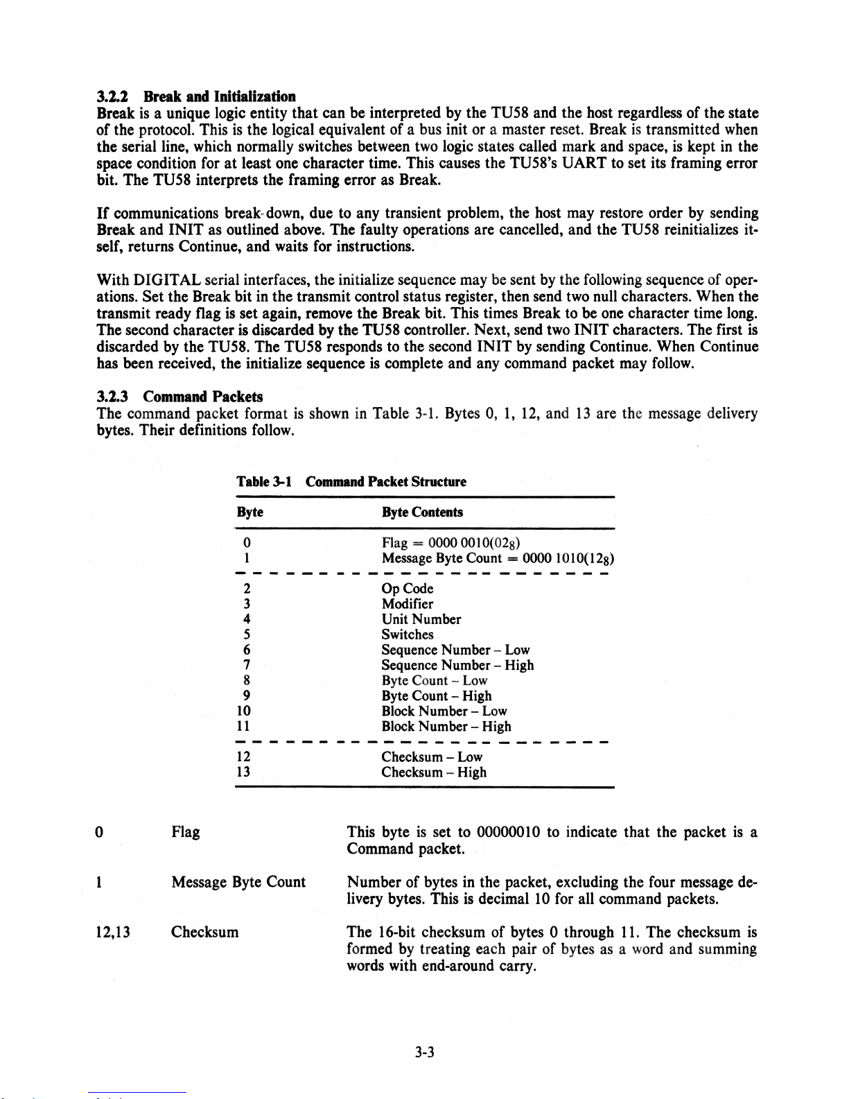
3.2.3 Command Packets
The command packet format is shown in Table
bytes. Their definitions
follow.
Table 3-1 Command Packet Structure
3-1.
Bytes 0,
1,
12, and
13
are the message delivery
is
o
1
Byte
o
1
2
3 Modifier
4 Unit Number
Byte Contents
Flag
= 0000 0010(028)
Message Byte Count = 0000
OpCode
101
O(
128)
5 Switches
Low
Low
is
Flag
6 Sequence Number 7 Sequence Number - High
8 Byte Count 9 Byte Count - High
10
11
12
13
Block Number Block Number - High
Checksum Checksum - High
This byte
is
Low
Low
set to 00000010 to indicate that the packet
Command packet.
Message Byte Count Number of bytes in the packet, excluding the four message de-
is
livery bytes. This
decimal
10
for all command packets.
a
12,13
Checksum The 16-bit checksum
of
bytes 0 through
formed by treating each pair
words with end-around carry.
3-3
11.
The checksum
of
bytes as a word and summing
is
Page 27
The remaining bytes are defined below.
Op
2
Code
Operation being commanded. (See Table
for definitions.)
34
and Paragraph 3.3
3
4·
5
6,7
8,9
Modifier
Unit Number
Switches
Sequence Number
Byte Count
Permits variations of commands.
Selects drive
Selects maintenance mode and specifies
Always zero for
0 or I.
TU58.
RSP
or MRSP.
Number of bytes to be transferred by a read or write command.
Ignored by other commands.
10,11
Block
Numbet
The block number to be used by commands requiring tape positioning.
3.1.3.1 Maintenance Mode - Setting bit 4 of the switches byte (byte 5) to I in a read command inhibits retries on data errors. Instead, the incorrect data
The success code in the end packet indicates a hard
is
delivered to the host followed by an end packet.
dt~.ta
error. Since data is transmitted in 128-byte
packets, a multiple packet read progresses normally until a checksum mismatch occurs. Then the bad
data packet is transmitted, followed by the end packet, and the operation terminates.
3.1.3.1 Special Address Mode - Setting the most significant bit of the modifier byte (byte 3) to 1
selects special address mode.
records
(0-2047) instead of 512-byte blocks (0-511). Zero-fill in a write operation only fills out to a 128-
In
this mode all tape positioning operations are addressed by 128-byte
byte boundary in this mode. To translate between normal addressing and special addressing, multiply
the normal address by
4.
The result is the address of the first I 28-byte record of the block. Add
I,
2, or
3 to get to the next three 128-byte records.
3.1.4 Data Packets
3.1.4.1 Radial Serial
is
packet
the command packet from host to the TU58. Next, the data
either direction (as required by read or write). After all data
If
the TUS8 encounters a failure before all data has been transferred, it sends the end packet as soon as the
Protocol-
A data transfer operation uses three or more message packets. The first
is
transferred in 128-byte packets in
is
transferred, the TU58 sends an end packet.
failure occurs.
The data packet
between
128
bytes
1 and
at
whereas the
message packets for the
host has enough buffer space, the
is
shown in Table 3-2. The flag byte
128
bytes. For data transfers larger than 128 bytes, the transaction
a time. The host
TU58 only
has
TU58 to send the Continue flag 0208 before sending the next packet. Because the
is
set to 0018. The number
is
assumed to have enough buffer capacity to accept the entire transaction,
128 bytes
of
buffer space. For write commands, the host must wait between
of
data bytes may be
is
broken up and sent
TU58 does not wait for a Continue flag between message packets when it
sends back read data.
3.1.4.1 Modified Radial Serial
entire transactions
at
the hardware selected data transfer rate, modified radial serial protocol (MRSP) may
be specified using the command packet switch byte. Bit 3 of the switch byte
3 remains set until intentionally cleared or cleared during power
Protocol-
When the host does not have sufficient buffer space to accept
is
set to specify the MRSP. Bit
up.
A good practice
is
to set bit 3 in every
MRSP command packet.
34
Page 28
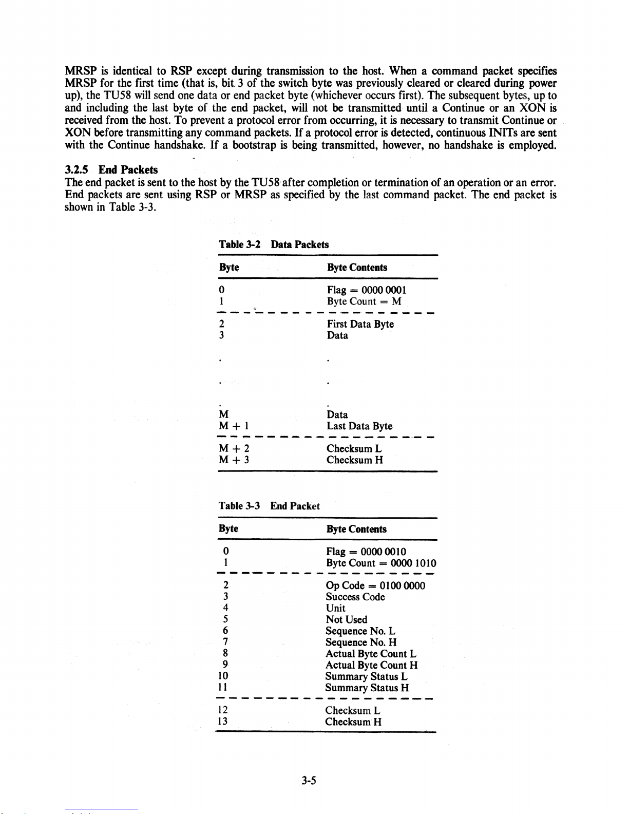
MRSP
MRSP
up),
the
and
including
received
XON
before
with
the
is
identical
for
the
ru58
from
transmitting
Continue
first
will
send
the
last
the
host.
handshake.
to
time
RSP
except
(that
is,
bit 3 of
one
data
or
byte
of
the
To
prevent a protocol
any
command
If
a bootstrap
during
end
packet
end
packet,
packets.
transmission
the
switch
byte
will
error
from
If
a
is
being
to
the
byte
was
previously
(whichever
not
be
transmitted until a
occurring,
protocol
error
transmitted,
host.
When a command
cleared
occurs
first).
it
is
necessary
is
detected,
however,
or
cleared
The
subsequent
Continue
to
transmit
continuous
no
handshake
packet
during
bytes,
or
an
Continue
INITs are
is
employed.
specifies
power
up
to
XON
is
or
sent
.
3.2.5
The
end
End
packets
shown
End
packet
in
Table
Packets
is
sent
are
sent
3-3.
to
the
using
host
by
the
ru58
after
completion
RSP
or
MRSP
Table 3-1 Data Packets
Byt~
o
1
------------------
2
3
M
M+
as
specified
"
1
by
Byte Contents
Flag = 0000
Byte Count = M
First Data Byte
Data
Data
Last Data Byte
or
termination of
the
last
- - - -- ------ - - - --
M+2
M+3
ChecksumL
ChecksumH
command
0001
..
- -
an
operation
packet.
The
or
end
an
error.
packet
is
Table 3-3 End Packet
Byte
o
1
Byte Contents
Flag - 0000 00 1 0
Byte Count = 0000 1010
--------------,..---
--
10
11
12
13
3
4
5
6
7
8
9
2
-
--
--
Op Code - 0100 0000
Success Code
Unit
Not
Used
Sequence No. L
Sequence No. H
Actual Byte Count L
Actual Byte Count H
Summary
Summary
- - - - - - -
ChecksumL
ChecksumH
3-5
Status L
Status H
---,-
Page 29
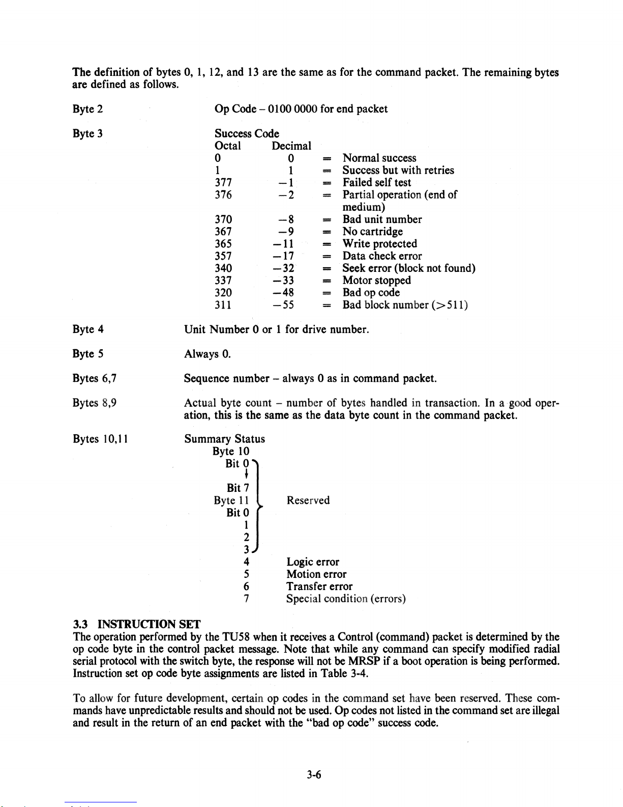
The definition of bytes
are defined
Byte
2
Byte
3
Byte
4
as
follows.
0,
1,
12,
and
13
are the same
Op
Code
- 0100
Success Code
Octal
0
1
377
376
370
367
365
357
340
337
320
311
Unit Number 0 or 1
Decimal
-11
-17
-32
-33
-48
-55
0000
0
1
-1
-2
-8
-9
for
drive number.
as
for
the
command
for
end
packet
Normal
=
Success but
=
Failed self test
==
Partial operation (end of
=
medium)
Bad
-
No cartridge
-
Write protected
==
Data check error
-
Seek error (block
==
Motor stopped
==
Bad
-
Bad
==
success
with
unit number
opcode
block
number
packet. The remaining
retries
not
found)
(>
511)
bytes
ByteS
Bytes
6,7
Bytes
8,9
Bytes
3.3
The
op
serial
Instruction
10,11
INSTRUcnON SET
operation
code
protocol
byte
set
performed
in
with
op
AlwaysO.
Sequence number Actual byte count - number of bytes handled
ation, this
Summary Status
Byte
Bit
Bit
Byte
Bit
by
the
TU58
the control packet
the
code
switch
byte
byte, the
assignments
is
the same
10
0
•
7
11
0
1
2
3
4
5
6
7
when
message.
response
are
always 0 as
as
the data byte count
Reserved
Logic
Motion
Transfer error
Special condition (errors)
it
receives
Note that
will
listed
in
error
error
a Control
while
not
be
Table
in
command packet.
(command)
any
command
MRSP if a
3-4.
in
transaction. In a
in
the command packet.
boot
packet
can
operation
is
determined
specify
is
being
<good
modified
performed.
oper-
by
the
radial
To
allow
for
future
mands
and
have
result
unpredictable results
in
the return of
development,
an
end
certain
and
should
packet
op
not
with
codes
be
used.
the "bad
3-6
in
the
command
Op
op
codes
code"
set
not
listed
success
have
in
code.
been
the
command
reserved.
These
set
are
com-
illegal
Page 30

Table 3-4 Instruction Set
OpCode OpCode
Decimal
0 0 NOP
1 1 INIT
2 2
3 3
4 4
5 5 Position
6 6
7
8
9
10
11
Octal
7
10
11
12
13
IDstruction
Read
Write
(Reserved)
(Reserved)
Diagnose
Gctstatus
Set status
(Reserved)
.
(Reserved)
Set
The following is a brief description and usage example
OP
CODE'O
This instruction causes the TU58 to return an end packet. There are
packet is shown below.
BYTE
0
1
2
3
4
5
NOP
0000
0000
0000
0000 0000
0000
0000
0010
1010
0000
OOOX
0000
6 0000 0000
7
8 0000 0000 BYTE
9
10
11
12
13
The TUS8 returns the following end packet.
0000
0000 0000
0000 0000
0000
0000
0000
0 0000
1
2
0000
0100 0000
3 0000
4
S
6
7
8
9
10
11
12
13
0000
0000
0000
0000
0000
0000
0000
XXXX
ooox
XXXX XXXX
0000
0000
00IX CHECKSUM.L
1010
0010
1010
0000
OOOX
0000
0000
0000
0000
0000
0000
XXXX
XXXX
<
FLAG
MESSAGE
OPCODE
MODIFIER
UNIT
SWITCHES
SEQ
SEQ
BYTE
BLOCKNO.L
BLOCKNO.H
CHECKSUMH
FLAG
MESSAGE BYTE
OPCOPE
SUCCESS
UNIT
NOT
SEQ.L
SEQ.H
..
ACTUAL BYTE
ACTUAL BYTE
SUMMARY STATUS L
SUMMARY STATUS H
CHECKSUML
CHECKSUMH
NUMBER
NO.
(NOT
NO.
(NOT
COUNT
COUNT
(IGNORED)
USED
....
of
each.
BYTE
.
CODE
CNT
(IGNORED)
(NOT
USED)
USED)
USED)
L
H INVOLVED
CNT
CNT
L
CNT
H INVOLVED
no
modifiers to NOP. The
NO
DATA
NO
TAPE
POSITION
NO
DATA
NOP
3-7
Page 31

OP
CODE 1 INIT
This instruction causes the
this operation.
from
ant change to the
reinitializing itself. There are
OP
CODE 2
This instruction causes the
designated by the block number bytes.
reading until the byte count (command bytes 8 and 9) is satisfied. After data has been sent, the
sends an end packet. Byte 3 indicates success, success with retries, or failure
of
event
packet is recognized by the host by the flag byte. The host sees a command flag
a data flag
failure, the end packet is sent
(0000 0001).
The
low
Read,
TU58 controller to reset itself to· a ready state.
command 'packet
order checksum byte. The TU58 sends the same end packet as for
no
modifiers to
and
Read
with
TU58 to position the tape in the drive selected by Unit Number to the block
is
tbe same as for
Decreased
It
reads
at
the time
IN
IT.
Sensitivity
data
of
failure without filling up the data count. The end
NOP
starting
except for the op code and the result-
at
the designated block and continues
No
tape positioning results
NOP
of
the operation. In the
(0000 0010) instead of
after
TU58
There are two modifiers to the read command. Setting the least significant bit
TU58 to read the tape with decreased sensitivity in the read amplifier. This makes the read amplifier
data
miss
healthy. The read transaction between TU58 and host is shown for 510 bytes (just under a full block) in
Figure
3.2.3.1 and 3.2.3.2.
if any weak spots are present. Thus, if the TU58 can read error-free in this mode, the data
3-1.
Setting the most significant bit
COMMAND
(READ
HOST
PACKET
510
BYTESI
of
byte 3 to 1 selects special address mode. See Paragraphs
TU58
I
I
..
~
.
•
,I
•
128
,,I
128
12BBYTES
DATA I
BYTES
DATA
BYTES
I
DATA
I
of
byte 3 to 1 causes the
is
I I
•
..
I
126
DATA
BYTES
I
OP
CODE 3 Write, and Write
This op code causes the TU58 to position the tape in the selected
10,11
of
number in bytes
It
writes data from subsequent data packets into one or more. blocks until the byte count called out in
bytes 8, 9 of the command packet has been satisfied.
The controller automatically zero-fills any remaining bytes
the command packet and write data from the first data packet into
Figure
and
3-1
Read
..
Read
Verify
II
END
I
C()mmand
3-8
I
_.378
Packet
Exchange'
driveto
ina
512-byte tape block.
.
the
block
specified by the
that
block.
Page 32

There are two modifiers pennitted with the write command. Setting the least significant bit
to
1 causes the TU58
3
decreased sensitivity and test the checksum
TU58 sends an end packet with the success code set
to
data). Failure
read correct data results in a success code
error. Setting the most significant bit
to
write all
of
the
data and then back
of
each record.
of
byte 3
to
up
and read the data just written with
If
all
of
the
checksums are correct, the
to
0 (or 1
if
retries were necessary
of -17
(357
)
8
to
to
indicate a hard read
1 selects special address mode. See Paragraph
3.2.3.2. . .
of
byte
read the
The write operation has to cope
with
the fact that the TU58 only has 128 bytes
of
buffer space.
It
is
necessary for the host to send a data packet and wait for the TU58 to write it before sending the next data
is
packet. This
accomplished using the continue flag. The continue flag
0000 from TU58 to host. The RSP write transaction for both write and write/verify operations
Figure 3·2. The
MRSP write transaction for
HOST
COMMANO
PACKET
WRITE
620,
BYTES
DATA
128
BYTES
OATA
128
BYTES
DATA
128
BYTES
DATA
128
BYTES
DATA
108
BYTES
both
write and write/verify operations
russ
..
CONTINUE
..
TAPE
POSITIONS
AND
WRITES
OATA
..
CONTINUE
..
TAPE
POSITIONS
AND
WRITES
DATA
..
CONTINUE
..
TAPE
POSITIONS
AND
WRITES
DATA
..
I
CONTINUE
..
TAPE
POSITIONS
AND
WRITES
DATA
•
CONTINUE
I
..
TAPE
POSITIONS
DATA. TU58 ZERD-FILLS REMAIN·
ING
404
VERIFY.
B
LOCKS
CHECKSUMS.
BYTES
TAPE
JUST
ANO
OF
BLOCK.
REWINOS
WRITTEN
I
I
is
a single byte response of 000 1
is
shown
WRITES
IF WRITEI
AND
READS
AND
TESTS
is
shown in
in
Figure 3·3.
Figure
3-2
..
RSP
Write
I
ENb
SUCCESSIFAILUR~
I
MAo2S77
Transaction
3·9
Page 33

I
HOST
CONTINUE
COMMAND
PACKET
WRITE
6108YTES
DATA
1288YTES
CONTINUE
DATA
1288YTES
..
I
I
•
I
I
I
I
I
I
I
I
I
..
SEND
THE
IS
AFTER
CONTINUE
..
..
TAPE
AND
CONTINUE
..
TU58
"CONTI
FOLLOWING
NOT
THE
SELECTING
POSITIONS
WRITES
NUl!"
FIRST
DATA
HERE
ONLY IF
COMMAND
COMMAND
MRSP.
PACKET
PACKET
Figure
CONTINUE
DATA
1288YTES
CONTINUE
DATA
128
BYTES
CONTINUE
3·3
MRSP
..
I I
I I
•
II
I I
Write
I
I
I
..
..
..
..
SUCCESS/FAILURE
Transaction
TAPE
POSITIONS
AND
WRITES
DATA
CONTINUE
TAPE
POSITIONS
AND
WRITES
DATA
CONTINUE
WHEN
USING
END
REQUIRES
FROM
MRSP.
THE
TRANSFER
"X-ON"
REMAINING 8YTE
148YTES
I
AN
HOST
END
PACKET
''CONTINUE''
BEFORE
MA·10.a3
OR
EACH
3-10
Page 34

OP CODE 4 (Resened)
OP
CODE 5 Position
This
command
11.
After
OP
CODE 6 (Reserved)
OP CODE 7 Diagnose
This
command
and
RAM.
Fail).
Note that if the bootstrap hardware
handshaking
OP
CODE 8
This
command
OP
CODE 9 Set Status
This command
end
an
OP
OP
packet.
CODE 10 (Resened)
CODE
causes
reaching
causes
Upon
even
Get
is
is
11
(Resened)
the
TU58
the
selected
the
TU58
completion,
if the
switch
Status
treated
treated
as
as
to
block,
to
TU58
byte
position
run
specifies
tape
it
sends
its internal
sends
an
option
on
the selected
an
end
diagnostic
end
packet
is
selected,
MRSP.
a NOP. The TU58 returns
a NOP because
TU58
status cannot
packet.
with
an
end
drive
See
Paragraph
program
appropriate
boot
information
packet.
be
to
set
the
block
which
success
from
designated
3.2.3.2.
tests
will
be
the
host.
the
processor,
code
(0 = Pass,
transmitted
The
by
bytes
TU58
10,
ROM,
-1
=
without
returns
PASCAL TUS8 HANDLER ALGORITHM
3.4
The
following
collection of algorithms describes the basic functions required
system. These algorithms are written
illustrate the
software
examples
1.
logic
of operations
for
a particular
found
in
tudiagnose - Constructs and
host
Appendix
involved
computer
C.
The
built-in, self-test diagnostic. Returns the
2.
tuseek - Constructs and sends the command packet
in
tape inserted
from
the TU58
3.
turead - Constructs and
the tape
TU58
4.
tuwrite - Constructs and
from
end packet
the buffer area specified
obtained
In addition
to
the
routines are shared
in
from
above
by
the specified drive
end
packet
sends
the specified drive into a buffer area. Returns the
as
the result.
sends
the TU58
end
specific functions, algorithms
the TU58 function routines and are included
DEFINmONS
in
a pseudo-Pascal language and are therefore
in
causing the TU58
may
be
written
following
sends
is
a list of the functions described.
the command packet causing the TU58 to execute its
TU58
to
the specified
as
the result.
the command packet
to
perform the intended function. Actual
using
these algorithms
end
packet success
which
block.
which
causes the TU58
Returns the'success
causes the TU58 to.read data
success
the command packet
to
the specified TU58 tape unit. Returns the
packet
as
the result.
for
which
causes the TU58
supporting routines are
for
the sake of completeness.
for
along
code
code
using
only
with
as
the result.
obtained
also
the TU58
designed
the program
to
position
code
obtained
from
to
write data
success
provided.
in
to
the
from
the
code
These
a
Digital Equipment Corporation assumes
offers corrections should errors
by
any
system
suitable language implementation.
no
responsibility
be
present. These algorithms
3-11
for
the correctness of these algorithms,
may
be
copied
for
use
on
any
nor
computer
Page 35

CONSTANTS
{
Define
(Defines
single
some
byte
interesting
packet
flags
and
}
useful
constants
)
data
control
init
continue
xoff
{
Define
read.opcode
write.opcode
positlon.opcode
diagnose.opcode
end.pack.opcode
(
Define
success
failure
{
Define
co~mand.flag
command.count =
command.opcode =
co~mand_unit
data.count.low
data.count.hiqh
command.block.low = 10;
command.block.hi9h = 11;
multi-byte
initialization
some
1;
=
2;
=
4;
=
16;
=
19;
=
=
2;
=
3;
=
5;
=
7;
=
64;
=
0;
=
-127;
useful
=
0,
1;
21
=
4;
=
8;
=
9;
packet
sUbscript
opcodes
success
}
codes
values
)
}
(
Define
command.length
data.block
GLOBAL.VARIABLES
slngle.byte.packet
( Note
Its
sent,
message )
multl.byte.packet
CALLING.PARAMETERS { Parameters
unit.number,
no.bytes
buffer:
length
the
length
i.e.,
of
command/data
= 10;
=
128;
(Indicate
:
byte;
variable
is a function
N
is
block.number
:
INTEGER; ( Number
ARRAY[l
length
the
number
:
ARRAY[O
••
no.bytes]
quantities
messaqes
of
the
of
the
type
of
bytes
••
N+31
defined
:INTEGER; {
of
bytes
OF
byte; ( Data/message
used
array
of
contained
OF
byte;
by
the
SpeCified
in
}
by
all
defined
message
calling
message )
functions
below.
to
be
in
the
routines}
unit/block}
space)
}
3-12
Page 36

tudlagnose,
«
This
routine
BEGIN
«
Construct
necessary
to
Return
contained
IF
inltiallzeCdiagnose.opcode)=success
ELSE
END,
«
tudiagnose
runs
the
TU58
execute
the
and send
to
cause
its
value
In
the
the
tne
self-test
of
TU58
send.packet(packet,
tudiaqnose
END
tudiagnose
:=
qet.end.packet
:=
failure
•
self-test
command
TU58
diagnostic
pac~et
controller
diagnostic.
the
success
end
packet
code
••
command.length+2),
THEN
routine
BEGIN
}
tuseek
«
Coristruct
TU58
block.
the
TUS8
BEGIN
IF
ELSE
END,
turead
« tUleele }
(unit_number,
and send a
should
This
end
POSition
routine
packet
block.number),
command.
the
returns
~s
its
p,cket
specified
the
result
succe~s
••
Initiallze(posltion.opcod.)=success
«
Construct/send
packet
packet
packet
[command.unltl
[command.block.lowl
[command.block.hlgh]
send.packet(packet,
« Conclude
tuseek
END;
tUleek
with
:=
get.end.packet,
:=
failure,
(unit.number,
blocle~nUmber,
a
command
:=
unit.number;
command.lenQth);
an end
packtt
which
unit
Indicates
to
the
code
THEN
specified
sent
8EGIN
paCket •
:=
10W(block.number),
:=
highCbloCk.number),
)
buffer,
no.bytes),
tne
in
«
Constuct
'no.bytes'
from
the
succels
the
and send
from
tape
the
into a buffer
code
the
contained
BEGIN
IF
initiallze(read.opcode)=success
(
Construct
return
packet
low
[command.unitl
packettcommand.block.lowl
packet
[command.block.highl
send.packetCpacket,
command
unit
and
comllland·
byte,
packet
block
space,
in
t~e
required
specified.
returning
TU58
end
THEN
packetr
high
:=
operators
byte
respectivelY.
unit.number,
:= 10W(block.numDer);
:-
hiqhCblock.number),
command.lenQth);
3-13
to
Reads
the
packet
BEGIN
'low',
read
value
••
'high'
data
of
Page 37

( Get
If
ELSE
END
ELSE
turead
END; { turead
data
output
and
stutf
In
get_data_packet(buffer)=success
turead
turead
:=
:=
:=
failure
get.end_pac~et
failure
}
buffer
THg~
)
tuwrlte
(
Construct
unit
the
success
(unit.number,
and
and
block
specified
code
obtained
result.)
LOCAL.VARIABLES
count,
data.count
BEGIN
IF
lnltlallze(wrlte.opcode)=success
(
stuff
packet[comm'41nd.unltJ:=
packet[command.block.lowl
packet
send.packet(oacket,
{
If
continue
'put.byte'are
calls
data.count
wHILE
count
data.count
END:
block.number,
send a command
for
writing
buffer
area
to
from
:
INTEGER;
parameters
packet
data.
t~e
the
into
bufter,
specifying
write
tape.
TUSS
end
command
no.bytes);
the
Return
packet
THEN
packet
tne
data
the
as
BEGIN
)
from
the
unlt.number;
:=
low(block.number);
(command.block.highl
:=
hlgh(block.number);
command.length);
Is
received,
Implementation-dependent
send
data;
'qet.byte'
function
}
:=
no.bytes
qet.byte=contlnue
{
~ake
bloCkS
:=
mlnimum(data.count,
THEN
maximum
Of
DO
128
AEGIN
bytes
data.block);
eacn
put_byte(count),
send_P8cKet(buffer[no_bytes-data_count+11,
count);
:=
data.count
-
count
}
{
In
any
event,
tuwrlte
:=
END
ELSE
EhD;
(
tuwrite
Initialize
(
Initializes
communication
for
INlT
transmitted
or
the
first
tuwrlte
(oP.code)1
sent
:=
)
the
TUSS
llne,.followed
twice.
to
the
(command)
BEGIN
(
Set
communication
try
for
get_end_packet
failure
by
sending
by
The
specified
TUSS
as
byte
line
either
of a multI-byte
control
an end
break
the
single
operation
a
single
to
3-14
packet
characters
byte
byte
packet.
BREAK
}
at
end }
on
pac~et
Is
then
packet
the
}
Page 38

(
Delay
error
multIple
)
Character
walt(n.Character.tlmeS)I
(
Remove
BREAL
condltion
tIme
from
to
line
insure
•
framlnq
reset.brealc.bi
{
Initialize
packet
[command.flaQ]
packetlcommand.oPcodeJ
( Send INIT
slngle.byte.packet
Put.byte(sinqle.byte.paCket"
IF
Qet.byte=eontlnue
ELSE
initialize
END, « lnitialize
send.packet
( Send
LOCAL
information
...
VAR
1ndex,
(buffer,
!ABLES
check.sum,
BEGIN
( Must
begin
cneck.sum
check.word
:=
1=
flag
wlth
0;
command
)
tI
packet
to
TUSe
1=
THEN
:=
fallu'Tel
nO.bytes);
contained
cheCK.word :
CheCksum
0:
:=
control;
:=
inlt;
in
area
)
op.code;
)
Initialize
'buffer'
INTEGER,
initialIzation
:=
to
success
TU58
)
)
( Check
1f
even1
of
TRU~
FOR
for
if
index
IF
odd(lndex)
even/odd
the
operator
the
:=
1
arqument
TO
check.word
ELSE
BEGIN
check.word
check.sum
END;
put.bvte(buffer[lndex])
END;
IF
Odd(no.bytes)
check.sum
{
Now
output
'high'
return
THEN
:=
cheCksum
low
put_byteClowCcheCK_sum»,
Put.byte(high(check.sum)
E~D'
(
send.packet
)
bytes,
'odd'
performing
returns
15 odd )
no.bytes
DO
BEGIN
THEN
:=
bufferlindexl
1=
butfer[indexl*256
:=
check(check.sum,
cneck(check.sum,
information;
byte,
hlg~
byte
3-15
cnec~sum
a
Boolean
+
cheCk.word,
cnec~.wqrd)
check.word>;
operators
respectively}
only
value
'lOW',
Page 39

get.data.packet
(buffer),
( Gets
the
~buffer~
data
}
LOCAL.VARIABLES
index,
checK.sum,
BEGIN
(
Initlalize
check.word
check.sum
(
LOOk
fdr
IF
(check.sum<>data)
ELSE
8EGIN
( Get
Checksum
:=
:=
get.byte,
valid
data
checksum
data.count
check.sum
FOR
Index
buffer[index]
IF
odd(index)
check.word':.
ELSE
check.word
Check.sum
END
END
sent
from
0,
data
packet
al
the
:=
get.byte;
I.
check.sum +
:=
1
BEGIN
the
data.count
variables
packet
THEN
get.data.packet
from TU58,
butfer
TO
data.count
:=
get.byte,
THEN
bUfter(lndex]
:=
buffer(lndexl*256
:=
check(CheCk.su~,
TU58
and
stuffs
:
INTEGE~J
)
structure
calculatlno
Is
being
data.count*256;
DO
BEGl~
it
)
:=
filled
check.word)
into
failure
)
+ checkword,
IF
odd(data.count)
Check.SUM
(
Make
sure
check.word
check.word
IF check.word<>check.sum
get.data.packet
ELSE
get.data.packet
END
get.end.packet;
(
Get.
as
an end pacKet from
result)
LOCAL.VARIABLES
index,
BEGIN
check.sum
« Look
Check.sum~
.
for
:=
get.byte,
valid
IF (check.sum<>command)
OR
(get.byte<>end)
TH~N
:=
Check(Check.sum,
packet
:=
get.byte;
:=
CheCK.word +
was
the
check.word
command
check.word),
not
In
error
)
get.byte*256J
THF.N
:=
failure
:=
sut~ess
TUSS,
packet
OR
THEN
returning
I JNtEG£RJ,
structure
success
}
(get.byte<>command.length)
get.end.packet
:=
code
failure
3-16
Page 40

ELSE
BEGIN
{ Get
success
co~e
from
command
packet
)
get_end.packet
{
checK.sum
FOR
END;
«
cneck.word
check._ord
IF check.word<>check.sum
END
END,
check
( Computes
around
BEGIN
«
(
(argl,
The
1
if
a
carry;
Now
do
the
:=
Index
:=
check.word
checK.word
check.sum
MaKe
sure
:=
:=
get.end.packet
get.end.packet
ar92),
the
16
bit
carry
technique
function
the
sum
a
'carry'
of
value
:=
get.byte,
cheCKsum
calcUlatlon
checK(check.word,
1
TO 4 DO
:=
:=
:=
packet
check.word + get.byte*256,
check(check.sum,
BEGIN
get.byte,
was
not
get.byte,
check.word
+
get.byt~*256'
THEN
,:
failure
)
checksum
Of
of
TUS8 )
argl
returns a value
the
arguments
Of 0 is
returned
)
get.end.packet*256);
check.word)
in
error
and
)
ar92,
of
results
in
otherwise
using
)
end-
END;
Check
{ check}
{
:=
argl + arg2 + carry(argl,arq2)
End
of
algorithm
definitions
•
3-17
Page 41

CHAPTER 4
INSTALLATION
4.1 INTRODUCfION
This chapter contains installation, configuration, and checkout procedures for all the versions of the
TU58 DECtape II (-DA, -CA, -EA, -EB, -VA components).
4.2 RACK INSTALLATION (-DA Version)
4.2.1 Rackmount
TU58-DA mounts in 13.2 cm (5.1 in) of standard 48.3 em (19 in) width rack.
The
so
that the'2 m (6
any power outlet.
4.2.2 Unpacking
The TU58-DA shipping carton contains the following items for rackmounting.
ft)
power cord can reach a power controller outlet box such as the DIGITAL
1 TU58"EB
1 Bezel
2 Mounting brackets
Support brackets
2
2
Support bracket extenders
Phillips trusshead screws 10-32 X
24
24 Internal lock washers
12
U-Nut retainers
6
Keplocknuts
1 Line cord (120
2 Fuses
(3/8
10-32 X
V)
A and
3/4
3/8
A slow-blow)
1/2
in
It
should
be
located
861
or
4.2.3 Power Selection
Detachable line cords for
cord receptacle meets European
lects 115 V or 230 V (Figure 4-1).
1.
Set the voltage switch to the correct value using a small screwdriver.
115 V and 230
Switch
Position
Left
Right
If
the TU58 is plugged into a 230 V circuit while set
for 115
V,
and two fuses are supplied with the TU58-DA. The line
IEC
standards. A switch
Voltage
115V
230 V
CAUTION
V,
it may
be
severely damaged.
4-1
on
the back of the tape drive rear panel
Range
90-128
180 - 256 Vrms
Vrms
se-
Page 42

FUSE
POST
120/240V INTERFACE CABLE CABLE SHIELD
SWITCH CONNECTOR GROUND
SCREW
FUSE
POST
120/240V INTERFACE CABLE CABLE SHIELD
SWITCH
CONNECTOR GROUND
\.
SCREW
000
POWER
SWITCH
(A) NON·FCC COMPLIANT CONFIGURATION
2.
From the two fuses provided, select and
fuse post, use a 3/16-inch blade type screwdriver:
Figure
(B)
4-1
TU58-DA Rear Panel
instaH
POWER
SWITCH RECEPTICAL
LINE
CORD
FCC
COMPLIANT CONFIGURATION
the proper fuse
Press in the fuse post cap and turn it
000
in
the fuse post. To open the
counterclockwise. To close the fuse post, use the screwdriver to press in the cap and turn it
clockwise.
4.2.4
The TU58
Removing
is
shipped prewired for operation at 38.4K baud transmit and receive on RS-423. If a
figuration change
Voltage
115V
230V
Bottom
is
Plates
for
necessary, the bottom plates must be removed
Fuse
3/4
3/8 A slow-blow
Controller
A slow-blow
Board
Configuration
in
order to gain access to the controller board. Use the following procedure to remove the bottom plates. (See Paragraph 4.7 for
figuration information.)
MA~7e3().a3
concon-
1.
Disconnect the power cord and interface cable from the rear panel of the TU58 (Figure 4-1).
2.
Place the TU5S upside-down on a flat working surface
3.
Remove the two Phillips head screws and lock washers from the front plate. Remove the
so
the rear panel faces you.
front plate, exposing the two tape drives.
4.
Remove two Phillips head screws and lock washers from the bottom of the rear plate and one
Phillips head screw from the rear panel at the left side of the interface cable connector.
flat
Remove the power supply assembly by lifting it out of the housing (with internal cables still
TU5S.
4.2.5
attached) and placing it rightside-up next to the
Rackmounting
Procedure
The following procedure enables one person to install the TU58-DA in the rack using a number 2 Phillips screwdriver.
1.
With the power cord and interface cable removed (Figure 4-1), carefully place the TU58-DA
upside-down on a flat working surface
2.
Remove the rubber feet if attached by removing the screws that hold them
4-2
4-1). Refer to Figure
so
they are flush with the left side. Fasten
two
screws and two lock washers.
and align the
so
the front of the device
two
support brackets on the bottom of the TU58-DA
down
the right side of each support bracket with
is
facing you.
in
place (Figure
4-2
Page 43

Figure
3.
Fasten the mounting bracket to the left side of the TU58-DA with two screws and two lock
washers
the other mounting bracket in the same manner using
lock nuts to secure it to the support brackets (Figure 4-3).
4.
Attach four U-Nut retainers (two per side) to the front vertical rails (Figure 4-4). Refer to
Figure
5.
Open the back of the rack. Attach four U-Nut retainers to the rear vertical rails (Figure 4-6).
6.
If
with four screws, four lock washers, and four lock nuts.
tom holes (Figure 4-7).
7.
Turn the TU58-DA rightside-llpand while supporting it with one hand, place it into position
in the rack.
so
the ball stud faces forward (bend in bracket toward center of TU58-DA). Install
4-5
and position U-Nut retainers
a non-DIGITAL rack is used, fasten the support bracket extenders to the rear vertical rails
4-2
Installing Support Brackets
at
the desired height for the TU58-DA.
two
screws,
Use two per side in the top and bot-
two
lock washers, and two
NOTE
Be
sure
the
mounting
the
rear
vertical
8.
Fasten the mounting brackets to the front vertical rails with four screws and four lock washers (two per side in the top and bottom holes).
brackets are to
raus.
the
inside of
Install
the
mounting
9.
For DIGITAL racks, fasten the mounting brackets to the rear vertical rails (Figure
non-DIGITAL racks, fasten the mounting brackets to the support bracket extenders (Figure
4-7).
10.
Attach the power cord and interface cable and connect to the appropriate device or receptacle. Close the back of the rack.
11.
Install the bezel by pushing into place over the ball studs (Figure
the
two
bottom
earL
CAUTION
screws
first
4-3
to
avoid
bending
4-8).
4-6).
For
Page 44

Figure
4-3
Installing
Mounting
Brackets
MA-1472
Figure
4-4
Front
Vertical
4-4
Rail
U-Nut
Retainers
Page 45

2.22
(7/S:
1.59
(5181
8.04
2.88
(23181 (11181
1.59
(5/SI
T
13.2
(5.191
4.78
(17181
L_
VERTICAL RAILS
SALLSTUD
FRONT
L~
·SUBJECT
MEASUREMENTS
ARE IN
Figure
4-5
____
1j.-·-----:r:3~51-----eoI·1
10----(17.151----01
TO
INCHES.
Rackmounting
44.6
Io----~
CHANGE
ARE IN CENTIMETERS
the
EXCEPT
TU58·DA
----4~
~~1~~1
I
c:=:::J
c:::::J
• _ 13.2
48.3
----...I
(19.01
VALUES IN
U T
(5.191
PARENTHESES
4-5
Page 46

REAR
VERTICAL
SUPPORT
Figure
4-6
MOUNTING
Rear
REAR
VERTICAL
BRACKET
Vertical
SUPPORT
Support
U-Nut
MA·8417'
Retainers
Figure
MOUNTING
BRACKET
4-7
Fastening
SUPPORT
EXTENDER
Support
4-6
BRACKET
Bracket
Extenders
Page 47

Figure
4-8
Installing the Bezel
4.3 'RACK INSTALLATION(-CA Venion)
4.3.1 Rackmount
The TVS8-CA rackmount unit mounts in 13.2 cm
should be located
DIGITAL
861
so
that
the 2
m(6
or any power outlet.
ft) power cord can reach a power controller outlet box such as the
(5.2
in)
of
standard 48.3 cm (19 in) width rack.
It
To get to the mounting holes, remove the bezel (Figure
both hands. Rotate it out from the bottom and lift it away.
bezel may be removed by gripping it with both hands on the left edge with fingers or thumbs inside the
storage well. Pull sharply out and swing the bezel away.
If
the rack requires them, install four V-Nut retainers
TVS8 is light enough for one person to install.
mounting ears.
Metal
4-9) by gripping
lethe
unit is installed in a recessed rack, the
WARNING
bezels
are
heatry!
at
the holes spaced according to Figure 4·10. The
Put
the two bottom screws in first to avoid bending the
" ,
it
at
the top and bottom with
4-7
Page 48

--
Figure
Four brackets and hardware are included with the TU58-CA to support the back end of the chassis in a
rack.
Use the two long brackets for DIGITAL cabinets. The short brackets are extenders for the
brackets used in non-DIGITAL
er
supply screws, and attach to the side rails of the rack with the supplied clipnuts and screws. Hardware is also provided to fasten the extender to the long bracket
bracket should point to the center of the rack while the bend
of the rack.
4.3.1 Power Selection for the Rack Version
Une
cords for 110 V and 220 V and two fuses
receptacle meets European
Vor
220 V (Figure 4-11).
1.
. Set the switch to the correct value using a small screwdriver.
2.
Install a fuse in the fuse post.
lEe
If
the unit is
for 110
A 3/8
3/4
Amp
4-9
Bezel
and Ball Stud
cabinets~
Attach the long brackets to the chassis with the existing
are
standards. A switch
CAUTION
plugged
V,
it
may
be
Amp
'slow-blow
slow-blow fuse for 110 V.
on
into a 110 V circuit
severely
NOTE
fuse is
long
pow-
if
required. The bend
on
the extender should point to the outside
supplied with theTU58-CA. The chassis power
the back
damaged.
required
of
the rackmount cabinet selects 110
while
set
for 220
V,
a
on
the long
3.
Insert the appropriate power cord into the receptacle.
installation
is
complete.
4-8
Do
not plug it into an outlet until the
Page 49

FRONT
VIEW
8.04
(2318)
2.22
17181
1.69
(5/8)
2.88
(1118)
1.59
(5/81
L
'0
4.78
(1718)
-
t-
_______
1ot--------(19.0)--------.I
-T-
TOP
OF
BEZEL
WIDE
NARROW
WIDE
WIDE
BOTTOM
OF
BEZEL
-~-
•5 --------./
48
(1B.31
FRONT
OF
BOX
(BEZEL
48.3
REMOVEDI
0.95
(0.375)
o
@
o
e
Figure
-r-~--~------~~
13.2
(8.181
~--------~------------~
,..1·------'~~5)-----.l·1
14-
______
44•5
·---.:...-----.11
(17.5)
rr~~~~'~uT
(18.0)~
·SUBJECT
TO
4--10
CHANGE
Rackmounting
101-----.....;...-"--(19.0'----:...----.1
the
TUS8-CA
FRONT
~
~~~~)
•
48.3
i
I
..
--
4-9
Page 50

CABLE
SHIELD
GROUND
•
_.
110/220 V
SWITCH
SCREW
o
FUSE
POST
Figure
m~
4-11
LINE
CORD
RECEPTACLE
TUS8-CA Rear Panel
4.3.3 Remofing Module from Chassis
Refer to Figure 4-12 and perform the following steps.
1.
Disconnect the power cord.
2.
Remove the bezeL
3.
Twist a coin or screwdriver in the gap between the retainer bar and the lip
of
the bar out
4.
Pull the cage toward you a few inches and
two and reach in
the chassis and set it aside.
tum
at
the back of the cage to remove the power and communication cables from
the module connectors. Remove the cage entirely from the chassis and put it on a stable work
surface.
INTERFACE
O
CABLE
CONNECTOR
..
it to the right. Slide
of
the chassis. Lift
the
module out an inch or
5.
Reach in again
at
the back
the module.
6. Now slide the module
Be
careful around the
Oy
bent (and its edge is sharp).
without
pliers. Alignment is not critieai, but
disk does
it
cannot
replaced.
4.3.4 Reinstalling the Module
1.
With the connector edge facing into the cage, slide the module partially into the cage along
the card guides.
2.
Install the drive cables onto their connectors. Note that the drive cables cross each other,
with the left drive cable going to the right connector (as you look into the open end of the
cage).
of
the cage and remove the drive cables from their connectors on
out
of
the cage.
CAUTION
tIain
tachometer disk.
If
the disk gets bent
creasing,
it
might be straightened with
it
Dot
I'iIb against the optical sensor block.
be.
aligned;·
or
if
it is creased, it must be
.
It
is better
is
if
eas-
the
If
4-10
Page 51

Figure 4-12 Installing Cage and Retainer Bar
3.
Place the cage partially in the chassis and run the power and communication cables up to the
module onto their connectors.
4.
Slide the module all the
into the bottom of the chassis.
5.
Align the retainer bar parallel to the floor of the chassis, with the spring on top. Engage the
two
slots with the vertical sheet metal of the cage
end of the bar away and
the bar holds the cage in place in the chassis. The module should sit in the cage with its edge
just clear of the retainer bar springs.
6.
Replace the bezel and power cord.
way
into the cage and set the cage into the hooking tabs stamped
at
the middle of the cutaways. Press each
down, one
at
a time,
so
that the ends catch the lip of the chassis and
4-11
Page 52

4.4 INSTALLATION (-EA AND -ED VERSIONS)
The TU58-EA and
cords
for
115
are supplied
with
or a convenient location within reach of a
V and
the
-ED
are tabletop units that require a minimum amount of space. Detachable
230
V and
-EA.
two
fuses
The cords are 6
are supplied
ft
long,
enabling
power
outlet. See Paragraph
with
the
TU58-ED;
you
to place the TU58
4.2.3
tion information and Paragraph 4.2.4 for controller board configuration.
4.4.1 Tabletop Installation
1.
Disconnect the
power
cord and interface cable
from
the rear of the TU58 (Figure
only
the
115
on
for the correct
line
V cord and
fuse
a desk, tabletop,
power
selec-
4-1).
2. Place the TU58
upside-down
3. Install the four rubber feet
them to the bottom plates (Figure 4-13).
4.
Tum
the
TU58
5.
Connect the power cord, interface cable, and
4.4.2 Solid Mounting Installation
1.
Perform steps 1 and 2
2.
Install the four mounting brackets (bend
1.3
cm
(I/2
rightside-up and place
as
in) Phillips head
(Figure 4-13).
3.
Turn the TU58 rightside-up and place
on
a flat
working
usingthefour~
iiin
surface.
. .
1-.3cin -(1/2
the desired location.
cable
above.
screws
facing
and
it
the side
lock
washers
in
the desired location.
shield
in)
Phillips head
wire
to the rear panel.
of
the TUS8 housing) using the four
to
secure
them to the bottom plates
screws
to
secure
Figure
4-13
Mounting the TU58-EA and
4-12
MA-6471
-ED
Page 53

,
4.
Fasten the unit to the mounting surface using four screws through the holes of the mounting
bracket bends.
NOTE
The four screws needed to secure the unit to the
mounting surface are not supplied with the
TUS8.
5. Connect
the
power cord, interface cable, and
4.5 INSTALLATION (-VA VERSION)
The TU5S-VA
convenient location within reach
In addition, the
is
a tabletop unit that requires a minimum amount of space and can be placed
of
a dc power source. (See Paragraph 1.4.2 for power requirements.)
TU5S-VA can mount to the
If
reconfigiJration
before installing the TU58-V
4.5.1 Tabletop Installation
Paragraph 4.4.1 for installation procedure.
See
4.5.2 Solid Mounting Installation
Paragraph 4.4.2
See
4.5.3 Mounting the TU58-VA to the
1.
Attach the four rubber feet to the TU5S-VA as described
4.
(If
2.
Place the
.for
installation procedure.
solid mounting
SBll
(or BAll-VA) upside-down
SBll
is
desired, order hardware kit
cable.
shield wire
SBll
(or BAll-VA) if
so
NOTE
Is
necessaryt see Paragraph 4.2
A.
(or BAll-VA)
in
Paragraph 4.4.1, steps 1 through
PN
70-16753-00).
on
a flat working surface.
to
the rear panel.
desired.
in
a
3.
Remove the rubber feet from the SBl1 (or BAl1-VA) if attached by removing the screws
on
securing them to the bottom. Fasten the four brackets to the bottom (bend
the outside
edge) using four screws and lock washers (Figure 4-14).
4.
Position the
line up with the holes on the side of the
SBll
(or BAll-VA) rightside-up over the TU58-VA
TU5S-VA. Fasten to the TU58-VA using four screws
so
the mounting brackets
and lock washers (Figure 4-14).
5.
Referring to Figure 4-15, connect the interface cables and power cord to their respective
lo-
cations.
4.6 COMPONENTS
Figures 4-16 and 4-17 provide the mounting dimensions for the circuit board and drive mechanism. The
19
drive has a
plug toward the center of the board. The plug
tends 1.60 cm (0.62 in) from the front
cm (7.5 in) cable which plugs into the board connector with the wires coming out of the
is
keyed to ensure proper orientation. The cartridge ex-
of
the drive.
If
the drive
is
recessed in a panel, clearance must be
provided around the opening for fingers to grip the cartridge. Ideally.,the cartridge slot in a front panel
is
somewhat larger than minimum, to allow easy insertion. The opening should be at least the dimen-
1.3
sions of the cartridge,
cm (0.5 in) X
S.1
cm (3.2 in), located not more than 0.53 cm (0.17 in) above
the bottom mounting surface (line A in Figure 4-16). The drive must be free to float on its mounting
so
screws,
bezels or panels must not touch the drive.
4-13
Page 54

SCREWS
WITH
MOUNTING
•
MOUNT
LOCKWASHERS
TO
THE
TU5g.VA~
USE
RUBBER
WITH
10-32
SCREWS
FOR
TOP
MOUNTING
BRACKETS
• 4
MOUNTING
AND
SCREWS
LOCKWASHERS
TO
BAllVA
HANG
MOUNT
r
FOR
I I SOLID
FEET
X 1/2
INCH
TABLE
TO
BAllVA
BRACKETS
WITH
FOR
OR
TO
,
-
-L
-..,
¥
(SBl1) FIRST.
MOUNTING
•
USE
METAL
10
32x
MOUNTING
HARDWARE
•
DEC
1/2
INCH
PIN
BRACKETS
SCR
EWS
KIT
70 1675300
WITH
FOR
DC
POWER
Figure 4-14 Mounting Choices for the TU
SERIAL LINE
UNIT
(SLU)
GROUND
SCREW
. ;
DC
SOURCE.
BAl1-VA. TU58-VA
TUsS-VA
Figure
4-15
Interfacing the
TO
ON
ORSB11
58-VA
4-14
Page 55

f
4.57
(1.8)
t
8.18
(3.22)
8.255
(3.25)
5.23
(2.06)
10.46
(3.812)
9.68 1
~--(4.12)----t
--r
A
(.71)
1.80
Figure 4-16 Drive Outline Drawings
l3.50~
(1.38)DIA
1'1---(3.50)
8.88
MEASUREMENTS
CENTIMETERS
VALUES
ARE
IN
4-15
ARE
EXCEPT
IN
PARENTHESES
INCHES.
IN
.
Page 56

17.73
DEC
MATE:
WITH
I .
24.13
(9.50)
24.85
--t_1
PT
#12-13508-04 I
AMP #87133-5
#87124-1
-e04
________
24.72
CONTACTS
SERIAL
.
CONNECTOR
INTERFACE
ilfl·'91
I (5.19)
I
I
.-!
,.27.
(.501
1----------(9.791---------...
1--
1
____
.
76
'4
(5.821
____
r-r-~~~-========~~-~-~-~~~
AMP
HEADER
MATE:
WITH
HEAT
SINK:
3.0
(1.21
ABOVE
0.5(0.21
BELOW
1
12
3
GNO
5 +5
6
GNO
1--
____
1--------(6.98)-----+1
r--
________
1--------------(9.73)------+1
#87633-6 AMP#87272-8 I
AMP #87159-6
#87027
CONTACTS
POWER
CONNECTOR
,.....:::;DR:.::.;IV;..::E~O....,..-r_...,
.
____
64
'4
(5.77)
12:24
(4.821
.48
12.32
(4.851
13.18
MEASUREMENTS
MEASUREMENTS
Figure
4-17
ARE
IN
CENTIMETERS
ARE ± .013
(.005)
EXCEPT
CENTER
TO
Board Outline Drawings
VALUES
CENTER
IN
PARENTHESES
ARE
IN
INCHES
MA·a370
The board should be mounted on a flat surface with 3 mm (4-40) hardware and 1 cm
at
Both the board and the drive may be mounted
the drives,
1.80 cm (0.71 in) clearance is required; hole spacing
any angle. For mounting the drives to a surface above
is
given in the outline drawings. For
mounting the drives to a surface below the drives, an 8.18 cm (3.22 in) X 8.89 cm
is
cutout
required, with the same mounting hole spacing.
CAUTION
The mounting surface for the drives must
be
nat
within 0.64 em (0.025 in).
Mountfug hardware is included with each drive. There
of
each
the four mounting holes. Figure
4-18
shows one assembly; in addition
tion for the mounting surface, there is a specification for the depth
ing surface. To prevent extra compression
of
mounting surface. Any tapering
0.419
em
(0.165 in) the edge
4.7 INTERFACE STANDARDS
the mounting hole must be limited
of
the
SELECfION
of
the
shoulder
spring,
is
The TU58 is shipped with factory-installed jumpers for a transmission rate
423 unbalanced line interface. A variety
ers on the controller board. Table
of
standards and rates may be selected by changing the jump-
4-1
provides a list
is
a shoulder screw, spring, and flat washer for
the
not
more than 0.076
AND
SETUP
of
all the pins on the board and their functions,
to
the flatness specifica-
of
the shoulder screw in the mount-
shoulder screw should meet the
so
that
at
the screw's diameter
em
(0.030 in) below surface.
of
38.4K baud and the RS-
including the wire-wrap (WW) pins, interface, and power connectors.
(3/8
in) standoffs.
(3.50 in) chassis
top
of
the
of
4-16
Page 57

THE MOUNTING
FOUR
Figure
SURFACE
DRIVES
WITHIN 0.64
MOUNT
(0.075 in.) MAX THICK·
NESS
WITH
6-32
SPACES,
THREADED
0.076mm. (.030 in.)
MAX
OF
MOUNTING
ON
EACH
DRIVE
4-18
TU58 Drive Mounting Hardware
FOR
MUST
mm.
ON
0.19mm.
FLAT
SURFACE
6-32
NUTS,
THREADED
OR
ON
INSERTS.
PENETRATION
SHOULDER
SURFACE.
THE
BE
6-32
INTO
ON
FLAT
(0.025 in.)
MA·S764f,
4.7.1 Selecting Interface Standards
The serial interface operates
on
full-duplex, asynchronous, 4-wire lines
at
rates from 150 baud to 38.4K
baud. The transmit and receive rates may be independently set. Each 8-bit byte
no
start bit, one stop bit, and
with EIA
RS-422 balanced or RS-423 unbalanced signal standards. When set to RS-423, the TU58
parity. The line driver and receiver may be set to operate in accordance
compatible with devices complying with RS-232-C.
is
transmitted with one
is
The TU58
imum wire length that may be used at that data rate
is
approximately
is
shipped prewired for operation at 38.4K baud transmit and receive on 1\S-423. The max-
in
an electrically quiet environment like an office
27
m (90 ft). The wire used with any installation should be
diameter.
Longer wire runs may be made if data rates are reduced.
RS-423 and can be used over
than
rived from the EIA standards, illustrates the variations
rates. For more information, consult the standards
at
least 1200 m (4000
for RS-422 and RS-423 published
in
Industries Association.
4-17
no
less than
RS-422
ft)
is
considerably more noise-immune
at
any TU58 data rate. Figure 4-19, de-
24
A WG
distance needed by RS-423 for different data
by
the Electronic
Page 58

Table
4-1
TU58 Module Connections
Wire-Wrap Pins
WWI
WW2
WW3
WW4
WW5
WW6
WW7
WW8
WW9
WWIO
WWll
WW12
WW13
150 Baud
300 Baud
600 Baud
1200 Baud
2400 Baud
4800 Baud
9600 Baud
19200 Baud
38400 Baud
UART Receive Clock Input
UART Transmit Clock Input
Auxiliary A (to interface connector pin
Auxiliary B (to interface connector pin 10)·
.
I)·
WW14
WW15
WW16
WWI7
WWI8
WW19
WW20
WW21
WW22
WW23 }
WW24
Factory
Ground}
Boot
RS-423 Driver
RS-423 Common (Ground)
Transmit
Transmit
RS-422 Driver+
RS-422
Receiver Series Resistor
(Jump for RS-422)
Test Point
Line+
Line-
Driver-
Serial Interface Connector
J2 - 10 Auxiliary B
J2-9
J2
- 8 Receive Line +
J2
-7
J2-6
Power Input Connector
J1-1
Jl-
3
JI-
5
JI-6
Ground
Receive
Key (no
connection)
+12V
Ground
+5V
Ground
Line-
.
Connect together for auto-boot
on power-up.
J2-5
J2-4
J2-3
J2-2
J2-1
Ground
Transmit
Transmit
Ground
Auxiliary A
LineLine+
DrfveCable
J3,4-1
J3,4-2
J3,4-3
J3,4-4
J3,4-5
J3,4-6
13,4-7
13,4-8
• For optional use, such as timing signals from baud clocks.
CartL
No Connection
Permit
Signal Ground
Motor +
Motor-
+12V
Tachometer
L
4-18
13,4-9
J3,4-10
J3,4-11
J3,4-12
13,4-13
J3,4-14
13,4-15
J3,4-16
LED
Head
Shield Ground
Erase Retum
Erase 1
Erase
0
Head Retum
Head
0
Head 1
Page 59

1200 4K
M
FT
300
lK
M
FT
600
150
FT
M
CABLE
LENGTH
100
30
FT
M
50
15
FT
M
10
3
FT
M
Figure 4-19 Data Rate and Cable Length for RS-423
4.7.2 Connecting Standards Jumpers
The jumper pins are standard
A
WG
wire and a hand tool. Other techniques that may be used include slip-on connectors, such as
DIG
IT
AL
915 patchcords, 917 daisy-chain, or soldering. ,
0.635 mm (0.025 in) wire-wrap posts which may be connected using 30
300 600
DATA
"''''-
~"'''
'\~~
~('Q
,~"'-
~
~~
~(C'1!
&~
lK
2K 5K 10K 20K 40K
RATE
IN
BAUDS
RS·423
""2118
The baud rates may
Simply connect the pin with the desired baud value to either the XMIT or RCV pins or both. Figure
20 illustrates the pin locations, and Figure
The interface standards may be selected by connecting sets
in abbreviated form in Figure
is shipped prewired for RS-423 with pin
be
set independently for transmission and reception, or both can operate together.
4-21
the factory-wired configuration.
of
pins together. The connections are listed
4-20. The group of pins
17
connected to pin 19, and pin
17
through
24
are the interface pins. The module
18
connected to pin 20.
4-
No
other pins in the group are connected.
For RS-422, pin
should be tied to pin 19, pin 22 to pin 20, and pin
23
to pin
24.
No other pins
in
the
21
group are connected.
4.8
OPERATIONAL CHECKOUT
A confidence check
or keyboard console emulator
The light on the
4.8.1
Checkout
of
the operation
of
a host system without the use
TU58 board should
of
Interface
of
the newly installed TU58 may be performed through the console
of
an operating system device handler.
be
on, indicating a functional processor.
To address the serial interface device registers with the console (consult the system manuals for address
and codes), perform the following steps.
1.
Set the transmit control status register to send Break to the TU58.
2.
Remove the Break condition.
3.
Transmit INIT: 04 (octal) to the TU58.
4. Transmit a second 04.
5.
Examine the receive data buffer to find Continue: 20 (octal)
4-19
Page 60

DIAGNOSTIC
232117-19
423
18-20
422
21-19
22-20
23-24
LED
028
0
WW
24
++++++++
101
~
Id
EJ
WW
17
TP
+14
GND+
BO.OT+f:
160+
300+
600+
1200+
2400+
4800+
9600+
19.2K+
38.4K+
RCV+CLK
XMIT+CLK
AUXA+
AUXB+
WW
WW
1
WW
13
_
Figure 4-20 Interface Selection Jumper Pin Locations
MAo-23M
4-20
Page 61

38.4
KBAUD
Rev + XMIT
RS-423
o
o
o
o
o
o
o
(I.
o
o
c
c
c
c
ooooOObO
rnrnD
UA--2383
Figure
4.S.2. Configuring Interface Modules
This section lists the switch or jumper configurations recommended for DIGITAL's asynchronous serial
interface modules. These modules connect the LSI-II QBus or the
interface. Each module
the standard bus address (176500) and vector (300) for the TU58. For other speeds or addresses, read the
manual for the specific interface. And for TU58 configuration, see Figures 4-21 and 4-22. The interface
requirements are
EIA RS-423 voltage levels (RC232-C compatible)
Eight data bits
One start bit
One stop bit
No
Break enabled
4-21
parity
Factory Wiring
is
configured to run
as
follows.
at
the fastest speed possible (either 9600 or 38400 baud),
DC 0 DObbO
DTIDD
8800
BAUD
RCV
• XMIT
RS-423
Figure 4-22 TU58 Wiring (9600 Baud)
PDP-II
UNIBUS to the TU58's serial
..........
at
In the following tables, R means a jumper is
removed, and I means a jumper
OFF
packs.
of
the seating.
NOTE
is inserted.
refer to the positions on board·mounted switch
An
X means the TUSS
4-21
will
work regardless
ON
and
Page 62

DLVll-A
(M7940)
Jumper
A3 1
A4 1
A5 1
A6 R
A7
AS
A9
AIO
All
AI2
V3
V4
V5
V6
V7
FRO
FRt
FR2 I
FR3
NP
2SB
NB2 R
NBI
PEV
FEH R
EIA
Setting
1
R
1
R
R
R
I
1
I
R
R
1
1
R
R
I
R
X
1
Value
176500 (address)
300 (vector)
9600 (baud rate)
CLI
Cl2
Cl3
Cl4
DLVtt-E
(M8017)
Jumper
A3
A4 R
A5
A6
A7
AS
AIO
All
AI2
X
X
X
X
Setting
R
R
I
R
1
I
1
I
ValUe
176500 (address)
.
4-22
Page 63

DLVll·E
(M8017) (Cont)
Jumper Setting Value
V3
V4
V5
V6
V7
V8
R
R
R
I
I
R
300 (vector)
RO
RI
R2 R
R3 R
TO
TI
T2
T3
BG
P
I
R
X
X
X
X
I
R
E X
1 R
2 R
PB
C
CI
8
81 R
H
B
-B
-FD
·FR
R8
FB R
M
MI
R
I
I
R
R
R
I
I
I
R
R
R
9600 '(baud rate)
DLVll-F
Jumper
A3 R
A4 R
A5
A6
A7 R
A8
A9 R
AIO
All
AI2
(M8018)
Setting Value
R
I
I
I
I
I
176500 (address)
4·23
Page 64

DLVII-F
(M8028) (Cont)
Jumper
V3
V4
V5
V6
V7
V8
RO
Rl
R2
R3
TO
Tl
T2
T3
BG
P R
~
1 R
2
PB
C I
Cl
S
Sl
H R
B
B
lA
2A
3A
4A
SA
IP
Setting
R
R
R
I
I
R
I
R
R
R
X
X
X
X
I
X
R
R
I
R
R
R
I
X
X
X
X
X
X
Value
300
(vector)
9600
(baud
rate)
2P
3P
4P
EF
M
Ml
MT
X
X
X
I
R
R
R
4-24
Page 65

DLVlI-J (M8043)
Use channel 0
of
the factory-configured module for the TU58 interface. Change the baud rate for channel
o from 9600 to 38400 by removing the jumper from 0 to N and connecting 0 to Z. Refer to Figure 4-23.
Channel
0
is
now
compatible with the factory-configured TU58 with address 176500 and vector 300.
CHOAND
CHIEIA
SELECTION
RIO -
~f:r}c:H
sen
pe_
E~}
'----
CH2AND
CH3EIA
SELECTION
;~}l
P__
CH3
sen
E
ree}
~J-R
pe_
AS'"
AI2
__
AS
...
AIO
__
A,,
__
ABe_
C2e_
~~m
01)(
CHO
CHI COMMUNICATION LINE
~
--CH3
1
CH2
ADDRESS
VECTOR
PARAMETERS
AND
JUMPERS
AO_
A7
{
va-
V7_
3M
...........
BREAK
SELECTION
ICHANNEL3)
e_
Figure 4-23
DLVll-J
4-25
Factory Configuration Summary
Page 66

MXVII-A (M8047)
Use channel 0
on
factory-configured interface (address 176500 and vector 300). Refer to Figure 4-24
and Table 4-2
~I
eJ44
eJ43
eJ42
e
J41
eJ40
J38
m eJ29
~J38
.J29i1
Li
J35
.J27
J38
I
I·
Figure 4-24
1
:
~.~~~I
J3D
..
J22J
"J21
eJ20
JIB
.J18
eJ17
eJ1B
.Jl
•
eJ12
eJl1
eJl0
eJl
eJ8
MXVll-A
18
•
Jl
Jumper Locations
J7
C!e
J8J6
ee
J4J3
.... 4 .....
.H
..........
--
4-26
Page 67

Table 4-2
Function
MXVII-A
Standard Factory Configuration
Wire-Wrap Pins
From To
Level
RAM
bank 0
SLU
CHO,
address
SLU
address
ROM
SLU
vectors
SLU parameters J59
(eight data bits,
parity bit, one stop
bit) J61
177
560 J24 J19
CHI,
177560
bootstrap (TU58) J37
CHO(300)
CHI(60) .
no
J30
J32 J33
J31
J23
J28
J26
J25
J27
J21
J34 J37 L2
J33 J39
J29
J53
J54 J52
J56 J51
J54 J55
J62
J60
J59 J66
J63
J31
Ll
Ll
J32
JI8
L2
Ll
Ll
JIO
Jl5
JI4
Jl3
J38
J22
Jl5
J57
L2
Ll
Ll
Ll
Ll
Ll
L2
L2
Ll
Ll
Ll
L2
J6l
J64
J63
J62 L2
J65··
Ll
Ll
Ll
L2
L2
Baud
rates
Bread generation
(Half option)
Crystal clock
CH0(38400)
CHI(9600)
J45
J46
J6 J7
J68
J50 LI
J48
J67
Ll
Ll
Ll
4·27
Page 68

DLtl-D
(M7800
or
M7800-YA)
Jumper
A3
A4
A5
A6
A7
A8
A9
AIO
V3
V4
V5
V6
V7
V8
Baud rate switches
Position 8 for
NP
2SB I
EPS X
NB2
Nl
9600 baud receive and transmit with speed group 4 crystal (4608 MHz).
Setting
I
I
I
R
I
R
I
R
I
I
I
R
R
I
R
R
I
Value
176500 (address)
300 (vector)
Jl
N2
J3
J4
J5
J6 R
J7
J8 I
J9
JI0
JlI
I
R
R
I
I
R
R
I
R
4-28
Page 69

DLll-E
(M7800)
Jumper
A3 I
A4 I
AS
A6
A7
A8 R
A9
AIO R
V3
V4
V5
V6
V7
V8
Baud rate
Position 8 for 9600 baud receive and transmit with speed group 4 crystal (4608 MHz),
NP
2SB
EPS X
NBI R
NB2 R
NI
switches:
Setting
Value
I
"R 176500 (address)
I
I
I
I
I
300 (vector)
R
R
I
R
I
I
JI
J2
J3
J4
J5 I
J6
J7 I
J8 I
J9
JI0
J
11
I
R
R
R
I
R
I
R
4-29
Page 70

DLll-W
(address 176500, vector 300, speed 9600 baud)
(M7856)
Switch
2 1 X
3
4
Pack
Switch
Number
2
3
4
5 On
6
7 On
8
1
2 On
3
4
,
6-10 X
1 On
2 X
3
4
5 On
6
7
8 X
9
10
Position
Not
placement unspecified)
X
orr
orr
orr
orr
On
orr
orr
On
orr
orr
orr
orr
X
orr
used (Switch
5 1
6
9
orr
2
3
4 On
5
7
8 On
10
On
orr
orr
On
On
On
orr
4-30
Page 71

4.8.3 Checkout
I. Insert a tape cartridge into drive 0 (left side). (The TU58 should have sent Continue
already.)
2.
Transmit the following string of octal numbers to the TU58. (Consult the programming chapter
for an explanation of this format.)
of
Drive Command Function
2
12
2
o
o
o
o
o
o
200
200
o
204
212
The
TU58 should wind to the beginning
see Table 2-1, under
"TU5S does not respond to host."
of
the tape and read about half
of
the tape.
If
(208)
it does not work,
4-31
Page 72

CHAPTERS
OPTIONS
5.1
RUN INDICATOR
Each tape drive may have an LED indicator which lights to show tape motion. Since data loss can
if
occur
the indicator is
5.1.1 Installation
The indicator (which may be any device capable of handling 30 mA with a forward voltage less than
V) is wired in.series with the tachometer source indicator. Splice the run indicator into the wire from
pin 7
should be on the board side of the wire (symbol
dicator is available from DIGITAL (PN 11-10324), and wires with slip-on connectors are available to
join the indicator to the tach (cable number
indicator
a cartridge is removed while the tape is being written, the cartridge should not be touched if
on.
of
the drive connector. (Count from the end with the missing pin; that pin is number 2.) The anode
arrow pointing away from pin 7, Figure 5-1). The
70-16526) and to extend the board connector end to the
at
the front
of
the drive (cable numbet70-16525).
1.8
in-
Figure
TO
PIN
7
ADDED
J3,J4
PIN
+12V
PINB-----....I
PIN
5-1
LED
7
9---------'
Installation of Run Indicator
...---,
5-1
I
I
Page 73

5.2 BOOT SWITCH
5.2.1
Special provision has been made for interfacing the TU58 to the
The TU58
using keyboard ODT. This means that a keyboard cannot be connected at the same time. This arrangement
reload and restart an unsupervised process controller or similar application. The Boot switch allows a
manual reboot without powering down to cycle the automatic sequence.
General
LSI-ll
is
placed at the system console address and vector, permitting it to "type" in a program
is
useful in an unattended control system, where the TU58 can automatically load and start or
ODT keyboard interpreter.
NOTE
Boot
mode
does
not
work
in
any
DIGITAL
ating
system
5.2.2 Operation
When the boot switch
manner.
1.
On power-up, the TUS8 checks for the presence
ond and begins the boot procedure.
2.
When the TUS8 is in the idle state,
close sequence causes a one-second delay (to allow for contact settling or to allow the host
processor to enter the halt mode),
The boot procedure positions the tape in drive 0 to block 0, sends Break to the host, and transfers
CII
characters from the tape to the host. A delay
from the
Any other character
The TU58 exits the boot mode following the transfer
enters the idle state. Because
be used with boot.
LSI-It.
is
connected according to Paragraph 5.2.3, the TUS8 operates in the following
If
the character sent
is
interpreted as a control chatacter, and time
of
environment.
of
the closed switch.
it
monitors the Boot switch. Any switch contact open-
and then the
is
is
ASCII 0 -
the timing requirement, only rates
ruS8
inserted between characters to allow for the echo
7,
this delay
of
the terminating character ASCII G (147g) and
begins the boot procedure.
oper-
It
then delays one sec-
is
one character time
is
allowed for
of
9600, 19.2, and 38.4K baud may
15
at
9600 baud.
characters of echo.
...
; .
A~
5.2.3
The boot pin on the board (WW16) may
action switch. Wires may be wire-wrapped. DIGITAL 915 patch-corded, or soldered to the pins. Placement of the switch and lead dress are not critical if adequate clearance
of
The boot tape contents are formatted to appear to the
operating under the
Installation
be
connected to ground through a normally closed momentary
the drive and the heat sink and power resistors on the module.
LSI-II
ODT keyboard interpreter.
is
provided around moving parts
as output from a console (keyboard)
5-2
Page 74

This
boots
drive
1000/012701
1002/176500
1004/012702
1006/176504
1010/010100
1012/005212
1014/105712
1016/100376
1020/006300
1022/001005
1024/005012
1026/012700
1030/000004
1032/005761
1034/000002
1036/042700
1040/000020
1042/010062
1044/000002
1046/001362
1050/005003
1052/105711
1054/100376
1056/116123
1060/000002
1062/022703
1064/001000
1066/101371
1070/005007
0
only.
roSS/PDP-II
APPENDIX A
TOGGLE-IN
BOOT
A-I
Page 75

APPENDIX
RSP
SEQUENCE
B
"NEWTAPE"
2
12
5
o
o
o
o
o
o
o
377
1
6
14
2
12
5
o
o
o
o
o
o
o
o
o
7
1::!
RSP
SEEK
8LOCK
SEEK
BLOCK
Seauence
TO
777
TO
0
Checksum
+
14
1
12
0
0
0
0
1
14
carrw>
0000101000000010
0000000000000101
0000000000000000
0000000000000000
0000000000000000
+
0000000111111111
~
Calculation
2
5
0
Octal
0
Addition
0
377
6
6
Exa.ple
Binar~
Addition
B-1
Page 76

SAMPLE
APPENDIXC
DEVICE
HANDLERS
cccccccccccccccccccccccccccccccccccccccccccccccccccccc
CCCCCCCCCCCCcccccccccccc
c c
C
C T U
C
C T U U 555555
C T U U
C T U U
C
C . C
CCCCCCCCCCCCCCCCCCCCCCCCCCCCCCCCCCCCCCCCCCCCCCCCCCCCCCCCCCCCCCCCCCCCCCCCCCCCCC
C
C
C
C
C
C
C
C
C
C
C
C
C
C
C
C
C
C
C
C
C
C
C
C
C
C
C
C
C
C
C
C
C
C
C
C
C
C
C
C
C
C
C
C
TTTTTTT
U U 5555555 88888 C
US
T U
T
Tne
following
handler
used
with
it
can
UUUUUUU
package
be
the
built
US
program
RT-!!
applications.
The program
implements
ierror = TUREAD(
Read
"bytecount"
unit
"unit"
starting
lerror = TUWRIT(
Write
"bytecount"
"buffer"
lerror
access
=
TUSEE~(
blOCk
Position
the
random-access
ierror = TUOIAG(
Run
tne
In
all
four
COdes,
!error
as
follows:
value
cases,
o
1
-I
-2
-8
-9
-11
-17
8 8
8 8 C
88888
58
58
555555
~8888
listing
_ritten
entirely
FORtRAN
into
ROM/PROM/EPROM
four
unit,
bloCk,
bytes
into
at
unit,
onto
the
random-access
bloCk,
TUS8
noted
unit,
the
bioCk
TUS8
)
TU58
internal
the
functions
meaning Of
t40rmal
Success,
TUS8
Partial
Invalid
No
success
but
failed
operation
unit
cartridge
Specified
Data
cheek
FORTRA~
SUP
P 0 R T C
8 C
e
contains
in
IV
compiler
user-program
bUfter,
from
data
area
bloc~
buffer,
bytes
drive
by
"bloCk".
from
"unit",
PACKAGE
a
compl~te
PDP-It
and
based
callable
bytecount
the
TU58
specified
"bloc~"
bytecount
the
data
starting
FORTRAN
object-time
LSI-1t
)
drive
on
)
area
TUS8
device
IV.
When
system,
microcomputer
entry
points:
specified
by
"buffer",
the
cartridge.
specified
at
tne
random-
)
cartridge
bloCk
controller
error
retries
self-test
nU~ber
is
cartridge
error
located
specified
In
by
"bloCk".
dlaanostlc
return a standard
Code
were
required
(TUDIAG)
(end-of-medlum
was
mounted
on
speCified
in
is
specified
_rite-protected
cartridge
drive
"unit"
function.
set
of
encountered)
drive
at
error
(TUWRIT)
C
C
C
by
by
C-l
Page 77

C
C
C
C
C
-32
-33
-48
-S5
-127
error
Motor
Invalid
Invalid
Communications
(block
stooped
operation
record
not
(TUS8
number (bad
error
found)
hardware
code
between
(error
block
See~
c
c
c
c
software
tnrough a OLV11,
whicn
has a receiver
assumes
that
the
DLVI1-J, DLVI1-E, DLV1!-F,
CSR
address
TUS8
assignment
controller
or
of
This
c
C
e
mode
software
only
operates
for
simplicity.
the
interface
in a non-interrupt-driven
The
e
e
e
e
e
program
Eguipment
on
any computer
its
rellaollity
is
Corporation,
neither
system.
on
any
licensed
and
may
Dlaltal
hardware,
nor
be
supported
copied
assumes
Digital-supplied
or
no
modified
responsibility
This
e
cccceCCCCCCCCccccccececccccccceeccceececccccecccccccec
c
INTEGER
FUNCTION
Tudlag
e
e
C cooe
Runs
TUSS
as
function
controller
result.
diagnostic
function,
returning
e
IMPLICIT
eO~~ON
INTEGER
Icmdpktl
(a-z)
packet(6)
e
e
C
Initialize
TUdiag =
IF
(Tudiag.ne.O)
a
command
Init(7)
GOTO
packet
100
wltn
the
DIAGNOSE
e
e
Now
transmit
the
paCket
to
the
TUSS
controller.
e
CALL
Sndpkt(packet,12,O)
c
C
e
100
And
ask
for
the
results
Tudlag = Getend(O)
RETUMN
END
of
t~e
diagnostiC
in
error)
in
tois
progra~)
number
host
and
is
interfaced
MXV11
176500(8).
by
Digital
or
passed)
TUS8
Interface
for
ule
otnerwise.
for
CcccccceCCCCCCCCCCCC
success
operation
tne
end
code.
packet.
c
e
e
e
e
C
e
e
C
C
C
C
e
C
100
INTEGER
Positions
by
as
IMPLICIT
COMMON
Initialize
Tuseek =
IF
paeket(3) = unit
packet(6) = block
Transmit
CALL
And
Tuseek = Getend(O)
RETURN
END
FUNCTION
"bloCk",
tne
(TUseek.ne.O)
ask
cartridge
returning
function
INTEGER
IcmdPktl
Init(S)
the
SndP~t(packet,12,0)
for
a
command
command
the
result.
paeket(6)
statuI
Tuseek(
in
the
(a-z)
packet
GOTO
100
to
unit,
"unit"
success
the
of
tne
block
to
with
TUSS
operation
)
r~ndom-access
code from
the
POSITION
controller
C-2
from
blOCk
tne
TUSS
operat1on
the
end
specified
controller
code
packet
Page 78

INTEGER
FUNCTION
TureadC
C
C
e
C
C code from
Reads "by
Into
the
access
bloCk
tent"
data
the
bytes
area
"block"
TUS8
from
speCified
on
controller
C
IMPLICIT
BYTE
COMMON
EQUIVALENC~
INTEGER
ca-z)
bufferCbytcnt),
Icmdpkt/"packet(6)
(lword,bword)
bword(2)
C
C
C
Build a READ
Turead =
IF
CTuread.ne.O)
Inlt(2)
command
GOTO
packet
packet(3) = unit
packet(5) = by
tent
packet(6) = olock
CALL
Sndpkt(packet,12,0)
C
C
C
~ead
10 chksum =
IF
Index
= 1
the
next
data
Getbyt()
(chksum.ne."OOl)
packet
GOTO
detent = Getbyt()
chksum = chksum +
Odd
= 0
DO
100,
odd =
IF
l=l,datcnt
.not.odd
(odd.eq.O)
GO
TO
datcnt'256
SO
bword(2) = 0
=
bwordCl)
Getbyt()
butferClndex) • bword(l)
GO
TO
50
100
C
C
C
100
bword(2) =
dhksum =
buffer(index)
Index = Index
(odd.ne.O)
IF
bwordCl) =
bword(2) =
IF
Cchksum.ne.lword)
GO
TO
10
Getbyt()
Check(chksum,lword)
= bword(2)
+ 1
ChkSum = Check(chksum,lword)
Getbyt()
GetbytC)
Found paCket which
GOTO
Is
400 Turead = Getend(chksum)
500
RETURN
END
INTEGER
FUNCTION
Tuwrlt(
C
C
C
C
C
C
C
C
writes
to
Returns
INPLICIT
BYTE
COMMO~
-bytcnt"
TUS8
drive
success
INTEGER
buffer(bytcnt),
Icmdpktl
EQUIVALENCE
Construct
a -RITE
bytes
"unit",
code from
(a-z)
bword(2)
packet(6)
(lwOrd,bword)
command
Tuwrlt = Inlt(3)
IF
(Tuwrlt.ne.O)
GOTO
packet(3) = unit
packet(5) = by
tent
packet(6) = block
C)LL
5ndpkt(packet,12,0)
unit,
th~
the
500
from.
400
SOO
not
data
unit,
from
data
starting
TUS8
packet
500
block,
TUSB
by
drive
"buffer",
cartridge.
as
the
and send
the
TUS8
!Proceed
packet;
block,
area
at
random-access
controller
and
bUffer,
select~d
starting
~eturns
function
it
to
the
to
400
try
for
bUffer,
specified
as
transmit
bytC"t
the
)
by
"unit-
at
success
random-
result.
TUS8
controll~r
It
not
data
end
packet
bytcnt
by
)
"buffer"
bloCk "blOCk".
function
it
to
result.
the
paCket
TUS8
C3
Page 79

C
C
C
C
C
10
C
e
C
400
C
500
datcnt = bytcnt
Prepare
flag
chksu~
IF
CALL
count
CALL
CALL
to
transmit a new
=
Getbyt()
(chksum.ne.
M
020)
PutbytCM001)
= MinOCdatcnt,128)
PutbytCcount)
GOTO
data
400
pack.t
!Proceed
ITransmit
l~ake
10utput
Sndpkt(bUfferCbytcnt-datcnt+l),count,count*256+
datcnt = datcnt • count
GO
TO
10
Received
Tu~rit
flag
was
not a CONTINUE.
= Getend(Chksum)
Try
RETURN
END
by
checking
to
data
packets
byte
for
400
if
packet
maximum
count
lND
packet.
for
CONTINUE
not
CONTINUE
flag
128
for
packet
M
001)
bytes
C
C Computes
INTEGER
e
technique
e
C
IMPLICIT
check
= I + 1
e
e
C 15
If
neither
poss1ble
e
IF (
(l.or.l).ge.O
e
C
e
C
C
C
C
C
C
C
C
100
200
C
C
e
C
C
C Wait
C
10
C
C Get
C
C
222
If
both
generated
IF (
(i.and.1).lt.0
If
only
only
If
IF ( check.lt.O ) GOTO
Perform
check
• Check + 1
RETURN
END
INTEGER
Gets
next
TUS8
controller
I~PLICIT
for
IF (
(IpeekC"176500).and."200).eQ.0
Character
Getbyt = IpeekC"176S02).and.255
WRITE(6,222)GETBYT
FORMATC·
RE'l'URh
END
FUNCTIOP4
l&-blt
for
checksum
TU58.
INTEGER
Input
Inputs
one
the
have
has
high-order
sum
doe I
end-around
FUNCTION
byte
from
to
INTEGER
input
character
from
R·,03)
Check C i., j )
of
Is
has
200
I and "
returned
Sum
(a-z)
ooerand
)
GOTO
hiOh-order
)
GOTO
100
bit
not
have
200
carry
if
required
Getbyt
the
serial
the
hOlt
machine.
(a-z)
aVailable
data
buffer
using
as
high-order
bit
set, a carry
set,
Its
then a carry
h1gh-order
interface
(DONE
)
and remove
end-around
function
bit
connecting
flag
GO
TO
10
extraneous
set,
bit
set)
value.
no
carry
is
always
occurred
set
the
bits
carry
C-4
Page 80

SUBROUTIHE
C
C
C
C
C
C Walt
C
10
C
C
C
e
222
8YTE
writes a byte
controller
IMPLICIT
IF (
Transmit
CALL
WRITE(6,222)OUT8YT
FORMAT('
RETURN
END
INTEGER
e
C
C
C
C
C
C
C
Initializes
Returns 0 If
IMPLICIT
CO~MON
Initialize
Inlt
packet(l)
packet(2)
packet(l)
packet(4)
packet(s)
packet(6)
e Loop
C
C
C
C
C
C
C Walt
C
C
10
C
C
e
C
C
C
C
C
C
C
C
C
SO
C
procedure
DO
Set
CALL
transmitting
DO
CALL
Remove
CALL
Discard
idummy • Ipeek(-176502)
Output
CALL
CALL
wait
IF (
CONTINUE
OUTBYT
for
(Ipeek(·176504).and.·200).eQ.0
Ipo~e(·176S06,outbyt)
= 0
to
50,
BREAK
IPoke(-176S04,-OOOOOl)
for
10,
Putoyt(-OOO)
IPoke(-176504,-OOOOOO)
putbyt(-004)
for
Getbyt().eq.-020
Putbyt(
to
INTEGER
output
character
T',Oll
.
FUNCTION
TuSa
properly
INTEGER
IcmdPktl
command
• 10*256 + -002
= opcode
0
=
= 0
0
=
0
=
allow
J=l,a
bit
BREAK
eight
1=1,8
BREAK
two INIT commands
Putbyt(-004)
CO~ditlon
any (pOSSiDly
, cheCk
to
the
the
host
(a-z)
interface
Inlt(
controller
(a-z)
packet(6)
eight
in
output
to
cause
for
outbyt
by moving
packet
retries
~UL
)
serial
machine.
ready
opcode )
initialized,
area
serial
framing
characters
on
output
erroneous)
to
CONTINUE
)
GOTO
interface
(DONE
It
to
for
operations.
with
of
entire
interface
error
under
interface
character
TUsa
controller
flag
100
connecting
bit
)
GoTO
data
buffer
-127
otherwise.
opcode
initialization
(XCSR)
in
TUS8
It
In
response
set)
10
register
specified
by
in
input
the
TUS8
buffer
~·5
Page 81

C
C
100
If
no
success
Inlt = ·127
RETURN
END
after
ei9ht
retries,
report
error
SUBROUTINE
SndpktCbuffer,bytcnt,chkini)
c
C
C
C checKsum.
C
C
Transmits a command
sending
IMPLICIT
BYTE
EQUIVALENCE
Chksum = chkini
odd = 0
"bytcnt"
CheCksum
INTEGER
buffer(bytcnt).
(iword,bword)
bytes
(a-z)
or
is
bword(2)
c
C
Loop
to
transmit
packet
e
DO
100,
odd =
IF
i=l,bytcnt
.not.odd
(odd.eq.O)
GOTO
50
c
e
C
If
an odd-numbered
bword(2) = 0
bword(l) = buffer(l)
GOTO
100
byte,
c
C
C numbered
C
SO
C
C
C
100
C
C
C
C
C Reads an end paCket from
C as
C
Perform
bword(2) =
chKsum
In
CALL
IF
Output
lword = chksum
CALL
CALL
RETU~h
END
INTEGER
I~PLICIT
BYTE
EQUIVALENCE
Checksum
byte
buffer(l)
: Check(ChKsum,lword)
either
(odd.ne.O)
the
case,
Putbyt(buffer(i»
computed checksum
Putbyt(bword(l»
Putbyt(bword(2»
FUNCTION
functlon
INTEGER
bword(2)
(lword,bword)
calCUlation
output
chksum = CheCk(chksum,lword)
GetendCchklnl)
value
the
(a-z)
c
c
C
C
C
c
c
C
10
chksum =
If
Input
already
IF
(cnksum.ne.O)
chksum =
Check
IF
(chksum.ne."002)
IF
(Getbyt().ne.l0)
IF
(Getbyt().ne."100)
chklnl
cnecksum
been
Getbyt{}
for
valid
read
1s
bY
GOTO
gNO
not
the
10
paCket
GOTO
GO
TO
GOTO
data
pacKet
from
"buffer",
initialized
contents,
remember
for
byte
to
for
packet
the
TUS8
success
zero,
caller.
structure.
500
500
500
to
the
TUS8
followed
from
the
one
byte
It
for
checksum
each
byte
Interface
controller,
code from
first
byte
It
Is
the
!MuSt
!Must have
!Must nave opcode =
have
controller,
by
"chkinl"
at a time
pair
returning
the
paCKet.
of
paCket
"chklnl"
flaq = COMMANO
byte
count = 10
the
uPdated
argument.
calculation
on
even-
has
value.
END
C-6
Page 82

c
C
C
C
C
C Read and
C
100 chklum =
C
C Read
C
If • valid
store
Getend •
chklum •
DO
bword(l) = Getbyt()
bword(2) • Getbyt()
bword(l) = Getbyt()
bword(2) = Getbyt()
IF
It
100,
1=1,4
transmitted
(Iword.eq.chksum)
c
C
C
500 Getend =
600
1+
, The
,
handler
,
, The program
,
,
,
I
,
,
I
,
,
,
,
I
,
,
,
,
,
,
,
,
,
,
Indicate
RETURN
END
.TITLE
.IDENT
fol10wlno
paCkage
IERROR = TUREAD(
Read
unit
Itartlng
IERNOR = TUWRIT(
Write
"BUFFER"
bloCk
IENROR = TUSEEK(
POSition
random-access
IERROR = TUOIAG(
Run
TU58
10.11
program
implements
"BYTECOUNT"
"UNIT"
"BYTECOUNT"
noted
the
,
,
In
all
I COdes,
,
,
,
,
,
,
,
,
,
,
,
,
cases,
as
IERROR
the
follows:
VALUa
o
1
-1
-2
-8
-9
-11
-17
-32
-33
packet
Getbyt()
Check(10*256."102,Getend*256)
dllcard
Check(chksum,lword)
Checksum
-127
written
Into
at
random-access
onto
by
the
TUS8
functions
Is
found,
remainder
-
checksum and compare
GOTO
or
transmllslon
NON-INTERRUPT
listing
In
PDP-II
four
FORTRAN-callable
UNIT,
bytes
the
data
UNIT,
bytes
TUSS
drive
"BLOCK".
UNIT,
TU58
cartridQe
bloCk
Internal
specified
)
controller
return a standard
NormU
success,
TUSe
failed
partial
Invalid
NO
eartrldQe
Specified
Data
check
Seek
error
~otor
stopped
read
of
600
contains a complete
MACRO
BLOCK,
from
the
area
block
8LOCK,
from
"UNIT",
BLOCK
located
NEANING
success
but
self-test
operation
unit
cartridge
error
(block
success
paCket,
error
DRIYE~
assembly
BUFFER,
TUS8
speCified
"BLOCK"
BUFFER,
the
data
starting
)
by
"BLOCk".
diagnostiC
OF
retries
(end-of-mediu_
number
Is
mounted
on
not
(TUS8
code
updating
with
TUS8
HANDLER
entry
BYTF.COUNT
drive
by
on
BYTECOUNT
area
at
in
drive
set
STATUS
was
Is
cartrldae
nardware
COO~
were
required
(TUDIAG)
specified
In
write-protected
found)
byte
checksum
computed
TUS8
lanQuage.
speclflp.d
the
specified
speelfled
device
points:
)
"RUFFF.R",
cartridge.
)
the
random-access
"UNIT"
function.
of
status
encountered)
error)
and
value
by
by
at
drive
the
(TUwRIT)
C-7
Page 83

1
;
;
;
This
; thrOugh a
,
:
;
,
, Equipment
,
;
;
software
which
SUbroutines
space
This
on
for
otherwise.
has a receiver
performances
program
any
computer
its
-48
-55
-127
assumes
OLV11,
were
1s
Corporat1on,
reliability
neither
system.
Invalid
Invali~
Communications
that
DLVI1-J, DLVI1-E, OLVI1-F,
CSR
wr1tten
are
not
liscensed
and
on
any
operation
record
the
address
w1th a
optimal.
may
01qital
hardware,
nu~ber
error
TUS8
controller
assiQnment
goal
of
nor
be
supported
copied
assumes no
Digital-supplied
code
readability:
or
(error
(bad
between
or
of
modified
responsib1l1ty
In
block
host
is
interfaced
MXV11
176500(8).
by
interface
time
DlGITAL
for
this
number
and
use
or
progra~)
passed)
TUSS
These
and
;-
;
Oefine
:
Define
:
Def1ne
, Macro
;
LAB:
.SBTTL
packet
F.OATA
F.CTRL
F.INIT
F.CON!
F.XOFF
Control
O.READ
O.wPIT
O.POS
O.OIAG
O.lHD
controller
DLRCSR
DLRBUF
DLXCSR
DLXBUF
to
send a cyte
.MACRO
T518
BPL
MOVS
.ENDM
Symbol
flag
Oefinit1ons
byte
=
=
=
=
=
packet
=
=
=
=
=
1nterface
=
=
=
=
to
PUTeYT
Ol'DLXCSR
LA8
ARG,
UDLXi3i.1F
PUTBYT
codes
1
2
4
20
23
op-codes
2
3
5
7
100
address
176500
OLRCSR+2
DLRCSR+4
DLRCSR+6
TU58
ARG,
?LAB
and Data Area
,
Data
Control
:
INIT pac\ct'!'t
;
CONTINUE
XOFF
perform
perform
perform
perform
packet
assignment
packet
packet
packet
packet
read
wr1te
seek
self-test
is
operat1on
operat1on
operation
an
End
packet
; Macro
;
NOTE:
into
LAB:
,
Data
, Area
;
PACKET:
;
Word
to
wait
If
ARG
the
high-byte
.MACRO
TSTB
BPL·
MOVE!
.ENDM
area
.PSECT
used
.BYTE
•
WORD
used
for a byte
Is a reg1ster,
GETSYT
UDLRC5R
LAB
il'DLRfHIF,
GETBYT
USERSO
to
build
F.CTRL,
0,
0,
to
collect
of
Control
0,
byte-pairs
from
the
ARG,
ARG
Rw,
10.
0,
TU58
the
register.
D,
0
par1ty
?LAB
LCL,
paCkets
for
REL,
16-bit
bit
CON
,
Control
e-8
w1ll
be
paCket,
cheCksum
s1gn-extended
length
calculation
= 10 •
Page 84

,
110RD:
1
Pure
,
1+
1
TUREAD
I
;
Description:
,
,
,
Inputs:
,
1 O(RS) = 4
,
,
,
,
1
;
Outputs:
,
,-
.BLKW
(ROM-able)
.PSECT
.SBTTL
see
RS
2(R5)
4(R5)
6(R5)
8.(RS)
RO
module
points
•
=
=
=
=
t6-~lt
TURF-AD
address
address
address
code
USERSI
heading
to a five
address
status
follows
R~,
I,
Read
word
of
unit
of
block
of
callers
Of
bytecount
code
LCL,
Data
From
standard
number
number word
REL,
input
word
CON
TU58
byte
buffer
FORTRlh
argument
b10c~
TUREAD::
;
auild a control
, Send
,
:
Receive
,
5S:
I
Re
,
each
,
10.:
the
ce i v e
pair
CALL
TSI
SNE
MOVS
MOVS
MOV
MOV
MOV
MOV
CLR
CALL
zero
MOV
GETBYT
CMPB
8NE
GETBYT
SIC
SIiIAB
815
SWAB
CL~
all
COM
BEQ
eLR
G!TBYT
MOVa
8~
I~If
RO
50S
'O.READ,
~2(R5),
~8.(R5),
~4(R5),
Control
'PACKET,
tt2.,
R2
SNOPKT
or
o(R5),
110
RO,
90'
112
'''C<377>,
112
R2,
112
R3
ch
ar
of
Characters
R3
20$
NOIID
WORD
WORD,
30.
packet
packet
Rt
more
U·.DAT~
RO
ac
te
rs
(R1)+
PACKET+2
PACKET+4
PAC~ET+8.
PACKET+I0.
to
the
RO
Data
paCkets
111
R2
1 n
th e Da
15
received.
TU58
ta
from
pac
I~itlallz~
If
error
return
operatton
store
store
I
store
,
PO
,
R1
,
P2 = init!al
send
TUSS,
I
Rt = address
get
If
, cheCk
:
oet
,
char
; form
I
RO = current
;
restore
R3
ke
t, u Pd
;
flip
,
branch
,
build
,
with
,
store
unit
byte
bloc~
points
= number
the
followed
flag
not a Data
for
byte
hi-byte
Initial
Is
even/Odd
at
flaq
Character
next
data
the
occured,
error
If
to
is
"RElO"
number
count
number
to
packet
of
chec~sum
Control
by an
of
byte
from
paCket,
End
packet
count
cnec~sum
checksum
byte
count
In 9 ch ec ks
second
data
byte
TU58
c~ller
bytes
from
byte
character
to
packet
End
callers
TU58
TU58
flip-flop
um
a s
character
pair
In
callers
send
packet.
buffer
in
RO
of
pair
buffer
20S:
G!TBYT
ADD
lOC
MOV8
wOIlO+l
wORD,
110
WORD+t,
RO
(Rl
)+
qet
,
update
;
with
,
store
C-9
second
end-around
byte
cnecksum
data
byte
pair
of
carry
in
callers
buffer
Page 85

30$:
SOB
R2,
lOS
loop
until
byte
count
is
zero
packet,
;
,
Receive
,
40$:
Checksum
;
50$:
, A
paCket
, Check
;
90$:
;caller
;
1+
TUWRlT
Descr1ption:
I
;
TST
SEQ
ADD
ADC
checlcsu~
GEnU
GETBYT
CMP
SEQ
error.
MOV
RETURN
was
see
BTTL
module
received
that
to
JMP
.S
See
R3
40$
wORD,
RO
from
"'ORO
WORD+l
wORD,
5$
Return
'-127.,
it
TU
WR
IT
heading
RO
RO
is
TU58
error
RO
from
an
Send
and
compare
COde.
the
TUS9
End
Packet.
oat a to
T
that
Us
8
;
If
:
finisn
to
get
compare
if
set
and
was
cheCK
odd number
checksum
computed
16~bit
with
the
same,
function
return
not a Data
End
of
data
bytes
value
checksum
computed cheCKsum
get
next
Data
value
to
paCket
caller
paCket.
and
to
return
error
In
packet
code
to
Inputs:
,
I
;
,
,
;
Outputs:
,
;
R5 = address
0(R5)
2(R5) = address
4(R5) • address
6(R5) = address
B.(RS) = address
RO
=
,-
TUWRIT::
Suild a Control
, Send
;
CALL
TS7
SNE
,",OVB
MOV~
MOV
MOV
the
MOV
MOV
CLR
CALL
TIl
0 V
MOV
Control
= 4
16-bit
IN
RO
99$
'O.WRIT,
~2(R5),
fa.(RS),
~4(R5),
'PACK!'.:T,
#12.,
R2
SNDPKT
@B.(R5),
6(R5),
ot a five
status
IT
packet
paCket
Rl
of
unit
of
block
of
output
of
bytecount
code
to
send
PACKET+2
PACKET+4
PACKET+8.
PACKET+l0.
to
the
RO
R3
115
word
standard
number
number word
buffer
word
to
the
TU59.
FORTRAN
byte
initialize
if
unsucceSSful,
return
TU58.
OD-code
set
set
set
RO = address
Rl
= number
R2 = 1nltial
send
R3
= number
R5 = adoress
to
unit
byte
blOCk
the
argument
the
caller
1s
"WRITE"
number
count
nu~ber
ot
paoket
of
block
TU58
of
packet
bytes
checksum
bytes
Of
callers
to
left
send
to
data
send
nut
fer
C-IO
Page 86

, Send
,
10$:
,
to
,
,
to
I
20S:
; A
byte
,
See
,
90$:
99S:
one
GETBYT
CMPB
SNE
PUTBYT
MOV
send
CMf
send,
BHIS
IIOV
PUTBXT
MOV
MOV
MOV
SitAe
ADD
CALL
SUB
ADO
8R
If
CALL
RETURN
or
was
the
more
Data
flO
RO,
90$
'F.DATA
1128.,
R3,
20S
fil,
1-14
RS,
R4, Rl
R4,
R2
,r.DATA,
SNDPKT
R4,
R4,
10$
rece1ved
paCket
GETENO
packets
,F.CONT
R4
R4
!/4
MO
R2
R2 R2 = initial
R3
RS
from
15 an
End
the
to
TU5~
packet.
the
that
TUSe.
J
;
I
,
was
get a byte
if
not
check
send
assume
if
RESET
send
RO
Rl = length
send
update
update
~ait
return
for
Data
less
F4
byte
address
=
the
for
not
CONTINUE,
128
than
to
packet
number
data
aCknowledgment from
a
CONTINUE.
to
from TU58
End
packet
packet
or
more
128.
actual
count
of
packet
of
packet
checksum
to
o~
buffer
caller
flag
bytes
bytes
number
fU58
bytes
pointer
left
to
left
left
left
send
to
TUS8
sene!
.S8TTL
,+
I
TUSEEK
;
Description:
;
;
Inputs:
;
I O(RS) = 2
; 2(RS) =
,
I
1
Outputs:
;
;-
TUSEEK::
; BUild
1
send
See
module
RS = address
4(RS)
RO = 16-b1t
=
CUL
TST
Sr.E
Control
,",ove
Move
MOV
the
Control
MOV
MOV
CLR
CALL
TUSEEK
heading
of
address
address
status
INIT
RO
99S
packet
,Q.POS,
~2(RS),
~4(R5),
'PACKET,
112.,
R2
SNDPKT
to
packet
1H
Posl
tion
the
three
of
of
PACKF.T+2
PACKET+4
PACKET+I0.
word
standard
unit
number
blOCk number word
code
send
to
fUSe.
to
the
TU58.
RO
TUS8
byte
FORTRAN
initialize
if
in1tialization
return
set
set
set
~O
P2
R2 = initial
send
error
op-code
unit
number
bloCk number
points
=
lenqth
the
packet
arqument
the
TUSS
to
caller
to
packet
of
P!Cket
checksu~
block
failed,
Get
an
End
packet
CLR
99$:
CALL
RETUR~
from
RO
GETEND
the
TU58
and
return
C-ll
to
1ndicate
return
caller.
no
to
caller
byte
pre-read
Page 87

·saTTL
;+
,
TUDUG
,
,
O~script1on:
I
I
I
Inputs:
: none
I
,
Outputs:
,
S~e
RO
II:
,-
TUDUG
mOdul~
16-blt
Run
h~adlnq
status
TU58
code
Local
Diagnostic
TDOUG:
,
,
;
0
•
;
99S:
:
Build
send
t~e
Receive
,+
, INIT
,
,
Description:
,
,
,
,
,
,
,
Inputs:
,
,
,
outputs:
,
,-
CALL
TST
BN!
Control
Mova
MOV
MOV
CLR
CALL
an
CLR
CALL
RETURN
.S8rTL INIT
INIT
to
This
followed
The
non~
RO = 16-blt
INIT
RO
998
packet.
'O.DIAG,
Control
'PACKET,
112.,
R2
SNDPKT
t:nd
packet
RO
GETEND
is
called
initialize
is
don~
by
TUS8
should
packet
R1
by
the
by
sending
status
PACKET+2
to
the
RO
and
return
Initialize
TUREAD,
TU58
causing
two INIT
reply
with a CONTINUE
code
TU58.
status
the
TUWRIT,
to
Its
a fram1ng
pack~ts
Initialize
,
If
Initialization
,
return
,
set
RO
II:
;
,
HI
=
,
R2
II:
,
send
code
,
in~icat.
,
get
:
return
TU58
TUSE!K,
power-up
~rror
to
error
op-code
address
length
initial
the
packet
to
caller.
no
the
€nd
to
and
state.
In
th~
the
packet.
the
code
of
of
checksum
byte
packet
caller
TUDIAG
TUS8,
TU58.
TU58
failed,
to
packet
packet
pre-read
caller
!HIT:
, Send
,
lOS:
208:
CLR
MOV
BREAk.
MOV
MOV
PUTSYT
SOB
CLf!
TSTB
RO
.8.,
Rl
II,
UDLXCSR
18.,
R2
.,0
R2, 20$
UDLXCSR
..
OLRBUF
,
a.sum~
r~try
;
,
start
,
s~nd
stop
remov~
;
C-12
success
eight
sending a break
nullS
s~ndlng
times
for 8 Character
any
tne
extran~oUI
break
before
input
failure
t1mes
byte
Page 88

I Send two INIT
I
I
see
,
:
Retry
,
9981
PUTBYT
PUTRYT
if
TU58
GUBYT
CMPS
BE-Q
SOB
falled.
MOV
RETURN
paekets.
,'.INIT
IF
.UllT
sent a Continue
R2
....
R2,
99.
Rl,
Return
.-127.,
CO~T
lOS
error
RO
paeket
status
to
,
,
,
caller.
send
two INIT
get a byte
If
CONT1NUE
r~turn
else
to
retry
paekets
fro.
~ac~et,
ealler
TUS8
,+
I
SNDPKT
I
,
Description
,
;
I
,
,
,
Inputsl
;
I
I
,
,
,
Outputs:
,
,-
SMDPKt':
, Send
,
IOU
2081
30$1
.SBffL
SNDPKT
send a mUlti-byte
SNDPKT
checksum
RO
Rl
R2
None
CLA
bytes
COM
BEQ
CLF<
MOVe
BA
MOve
ADD
ADC
PUTBYT
SOB
address
=
number
=
the
=
already
to
SNDPKT
is
called
will
to
Initial
-(SP)
TUS8.
(SP)
20s
WORD
(RO),
lOS
(RO),
WORD,
R2
(ROH
Rl,
also
the
of
of
been
lOS
Send a
by
packet
compute
TU58.
bytes
bytes
checksum
sent)
Update
ilOilO
WORD+l
R2
packet
TUREAD,
(either
the
to
send
to
send
(non-zero
16-blt
to
TUS8
IUWRIT,
Control
packets
,
Checksum
,
I
,
;
,
,
,
,
I
TUSEEK,
checksum and
If
make
after
flip
branch
set
up
with
s·tore
Update cnecksum
with
send
loop
and
or
Data)
part
of
the
oddleven
eaeh
oddleven
if
second
byte
first
second
end-around
tne
until
pair
byte
byte
data
byte
TUDIAG
to
the
send
packet
byte
fllp-flop
byte
flaq
byte
word
of
pair
of
carry
byte
count
to
TUS8.
the
palr.
of
pair
is
has
pair
Zero
(SPH
40.
WORD,
R2
R2
R2
R2
GEftND
R2
Cheek
40$1
TST
BEQ
AOD
ADC
PUTBYT
SwAB
PUTBYT
RETURN
.SBTTL
,+
I
G!TEND
,
,
Description.
,
,
GETEND
an
End
15
called
Control
by
paeket
for
TURElD,
from
End
PaCket
TUWRIT,
the
if
I
update
send
return
TU58.
C-13
odd number
computed cheeksum
16-blt
TUSEEK,
GETENO
to
ealler
and
v~rifles
eheeksum
of
data
TUDIAG
bytes,
to
that
accept
the
Page 89

,
, word
I
,
Inputs:
,
I
,
Outputs.
1
I·
GETEND:
,
If
I
IOU
,
Verify
,
received
RO
RO = 16-bit
flao
byte
TSTB
BNE
GE'l'Bn
that
ClifPS
aNE
G£TeYT
C"P8
ShE
GUBY!-
CfilP8
BNE
GETSYT
BIC
MOV
S"AS
ADD
ADC
packet
in
the
= a
byte
was
RO
lOS
RO
the
packet
RO,
908
RO
RO,
908
RO
RO, to.END ; and
908
RO
,AC<377>,
RO,
AI
'10.*256.+0.ENO+F.CTRL,
Rl
packet
already
status
not
pre-read
.r.CTRL
UO.
Rl
is
indeed
equals
read
by
code
by
comlnQ trom
RO
an
End
the
the
caller,
the
packet,
computed
caller
read
1£
read
TUSS
check
.
,
with
qet
I
,
clear
;
form
,
form
Rl
.
,
from
and
checksum.
or
zero
it
not
pre-read,
it-
Is
Indeed
Control
lenQth
oP-code
success
hi-byte
16-blt
16-blt
bytes
that
now.
=
=
code
cheCksum
cheCksum
already
the
an
End
paCl<et
10.
End
checksum
Control
In
Rl
received
packet.
,
Receive
,
20$1
I
Receive
I
Return
I
908:
1001:
and
MOV
G!TSYT
GETBYT
ADD
ADC
S08
Checksum
G£TaYT
GET8YT
CMP
8EQ
error
Mova
MDVB
RETURN
.END
ignore
14,
wORD
.ORD+l
WORD,
Rl
R2,
WORD
WORO+l
WORD,
100.
code
,-127.,
RO,
rest
Of
R2
Rl
20$
transmitted
Rl
for
transmission
RO
RO
End
packet,
from TUS8 and compare
,
error.
,
;
updatlnq
lOOP
return
return
cnecksu~.
four
times
with
status
to
caller
to
qet
8.
bytes
computed c-hecksum.
.s
16-blt
value
C-14
Page 90

APPENDIXD
CARTRIDGE REPAIR
D.l INTRODUCTION
Under unusual circumstances
of the hub. The tape
tape's wrap around itself. The procedures for looping the tape back onto the hub are given here to help
the user prevent the
proper handling and backup copying. Two procedures are given here.
tridge and the other
These are moderately difficult procedures requiring the use of small tools. Minimum tools are a number
1
Phillips head screwdriver and a small probe (a straightened paper clip can be used). Tweezers are
helpful.
is
loss
is
for the plastic-base cartridge.
of
controller failure or cartridge mishandling, the tape might come free
not fastened to the hub but
of important data. They are not a substitute for the customary precautions of
is
held in place by the elastomer belt and by the
One
is
for the metal-base car-
NOTE
Keep
magnetized tools away from the bulk
and do not touch the tape surface except
tape
ends because fingerprints cause errors.
paper clips stick to a tool, it is magnetized.)
(If
of
the
at
tbe
staples or
D.2 METAL-BASE CARTRIDGE
1.
Open the cartridge by removing the four baseplate Phillips head screws (Figure D-1) and set
it upright
on
the work surface with the cover still
Figure
D-l
Baseplate
000
Screw
on.
@
®
/
MA·2361
Locations
Page 91

2.
Lift the cover off.
NOTE
To remove the head gate, swing it out to clear the
tape before
lifting it
up.
Its replacement is optional.
A spring is in the bottom
3.
Thread the end of the tape around the tape guides (Figure D-2).
ELASTOMER
BELT
TAKE-UP -+--+--1
HUB
TAPE GUIDE
4.
Moisten the end
Figure
0-2
Threading the Metal-Base Cartridge
of
the tape with water to get it to stick to the hub.
DRIVE
ROLLER
of
the gate. (Figure
0-3).
SUPPLY
HUB
TAPE
GUIDE
MA-2312
5.
With a small amount
operate the drive roller with a finger to take up the tape.
some back tension on the tape. This keeps
6.
Continue to wind. Watch for the loose ends as it comes around.
tuck it under the next turn of tape with the probe. (Back up if the end
7.
Continue to wind a
8.
Hold the takeup hub and drive roller fixed, and rotate the supply hub to take up the slack.
9. Continue winding the tape about
10.
To reassemble the cartridge, reinstall the gate (if desired) by aligning the long and short ends
of
the spring with the long and short ends of the gate, as
11.
Drop the spring into the
rotate the long end of the spring around to the slot that
sion of the gate.
12.
Hold the gate halfway out
of
slack
at
the free end, insert the end between the hub and belt and
As
soon
as the tape
it
feeding straight into the hub.
If
it separates from the hub,
is
too long.)
few
more turns with the drive roller while applying tension to the tape.
20 turns before reassembling.
in
Figure D-3.
well
in the gate. Holding the spring
down
with a thumbnail or probe,
is
at a right angle to the long dimen-
Push the end of the spring into the slot; it should stay there
so
that the gate and the spring end do not touch the tape. Slowly
is
grabbed, keep
by
press the gate down onto its pin on the cartridge baseplate. Reach in with the probe and press
It
will
the spring down.
clear its holding slot and snap into position, closing the gate.
itself.
0-2
Page 92

MA-23&8
Figure 0-3 Head Gate and Spring
13.
Carefully lower the cartridge cover into place and reinstall the screws.
0.3
PLASTIC-BASE CARTRIDGE
Open the plastic-base cartridge case by removing the four baseplate Phillips head screws (Figure D-l).
Carefully remove the top.
0.3.1 Preparation for Threading
The four rollers and tape hubs in the plastic-base cartridge are held in their operating plane by the top
and bottom of the case together.
the elastomer belt can get folded
1.
To organize the parts for threading, remove and discard the head gate and spring. Take the
When the top
under the hubs.
is
off, the various parts tend to creep out of position, and
empty tape hub from the case and set it aside.
2.
Remove the floating roller (Figure D-4).
ELASTOMER+----BELT
Figure 0-4 Stretch the Belt with the Floating Roller
..
MA·2355
0-3
Page 93

3.
Rearrange the elastomer belt around the drive roller and the supply hub.
4.
Put the takeup hub
5.
Put the empty tape hub
6.
Using the top to hold the floating roller, belt and supply hub down, use a straightened paper
clip or pencil to guide the elastomer belt around the hub. The hub should seat against the
base with the belt around it.
D.3.2 Threading the Cartridge
1.
Pull several centimeters (a
(Figure
D-5).
Hold all parts
the hubs
slip. Then the procedure must
graph D.3
on
its
on
will
pin.
its pin.
few
inches) of tape off the supply hub and through the tape guides
NOTE
down
when
creep
moving
up
the pins and cause the belt to
them. Otherwise,
be
restarted
at
Para~
.•.
TAKE
HUB
Figure
2.
Moisten the end of the tape with water to get
3.
With a small amount of slack
D-5
Threading the Plastic-Base Cartridge
at
the free end, insert the end between the hub and belt, and
it
to stick to the hub.
SUPPLY
HUB
operate the floating roller to take up the tape.
4.
As
soon as the tape
is
grabbed, keep some back tension
on
the tape. This keeps the tape
feeding straight into the hub.
5.
Continue to wind. Watch for the loose end as it comes around.
If
tuck it under the next turn of tape with the paper clip. (Back up if the end
it separates from the hub,
is
too long.)
6.
Continue to wind a
7.
Now hold the take up hub, drive roller, and floating rollers fixed and rotate the supply hub to
take up the slack.
few
more turns with the floating roller while applying tension to the tape.
]),4
Page 94

D.3.3 Closing the Cartridge
on
Place the top back
in
pressed
slightly to clear the bottom. Reinstall the four baseplate screws.
the cartridge.
Do
not reinstall the head gate. The mirror
window
may need to be
Now use a finger to operate the drive roller and wind the tape about
before inserting the cartridge into a drive.
NOTE
The only reason for performing this exercise
copy the data from the injured tape as soon as
sible. Discard the cartridge after copying.
20 turns onto the takeup hub
is
to
pos-
0-5
Page 95

FIELD
REPLACEABLE
UNIT
APPENDIXE
SPARES
LIST
Module
Serial Controller
Regulator
Drive
Tachometer Encoder Wheel
Tape Cartridge
Module
Board
DIGITALP/N
54-13489
54-13609
70-15510
74-20649
36-15809
Option
TU58-XB
TU58-XA
TU58-K
Name
B-1
Page 96

Digital
Equipment
Corporation.
Maynard,
MA
01754
 Loading...