

Digital Equipment TU55 Instruction Manual
H-TU55
~--.
-
INSTRUCTION
MANUAL
DIGITAL
EQUIPMENT
DECTAPE TRANSPORT
"
-....
"'¢
CORPORATION
-_.
•
MAYNARD,
MASs4cHUS~TTS
,,'"
..
H-TU55
DECTAPE
TRANSPORT
TU55
INSTRUCTION
MANUAL
DIGITAL
EQUIPMENT
CORPORATION
•
MAYNARD,
MASSACHUSETTS
This
manual
customers
use
and
person
or
contains
of
Digital
maintain
organization
proprietary
Equipment
DEC
equipment.
for
any
information.
Corporation
Reveal
other
purpose
It
to
help
ing
the
is
prohibited.
is
provided
them
contents
to
the
properly
to
any
Copyright
1966
by
Digital
ii
Equipment
Corpora:tion
DECTAPE TRANSPORT TUSS
CO
NTE
NTS
Page
1.1
1.2
1.3
1
.3.1
1
.3.2
1
.3.3
1.4
loS
1. S. 1
1.6
2
2.
1
2.2
2.2.1
INTRODUCTION
General
Scope
Pertinent
Functional
Phys
TUSS
THEORY
Block
Detailed
Description
of
Manua
Documents
Manuals
Engineering
New
Module
ica I Descri
Electrical
Performance
OF
OPERATION
Diagram
Descriptions
Interface
AND
DESCRIPTION
..•.••.•.•••..••..•....••••.••.•.••....••.•••..
I
.••••..••••.•.•••••••••.•••.•....••....•...•..•.••
......•..................•.•......•.•.•...••...
..........•...................•.•.•.....•...•..••.•..
Drawings
News
Description
ption
Details
Characteristics
Analysis
..............
.........••..........•..•........•.......•
Bulletins
.....•.•...•.••..•.•..•..•...•.•..•..•...•...
.......•............•...•..•.....•..•••.•.•....
............••.••.•.............•....•.••....
.......•..................•...........•.......
•.•..............•.....•..•••..•.•.•..•..•..
.....•••..•.........•..•.••..•.••............•
...........•..•..........•.........
...................••...•.•.....•...
....••..•..........•.....•.....••...
:
........•..•............•.....•.......
1-1
1-1
1-2
1-2
1-2
1-2
1-3
1-3
1-4
1-6
1-9
2-1
2-1
2-4
2-4
2.2.2
2.2.3
2.2.4
2.2.S
2.2.6
2.2.7
2.2.8
2.2.9
2.2.10
2.2.11
2.3
2.3.1
2.3.2
2.3.3
Unit
Select
Command
WRITE
Interface
Read/Write
Tape
Motion
Remote
Local
(Manual)
Motor
Transport
Module
Descriptions
Type R303
Type WS13 Level
Type
G8S0
Lines
Lines
ENABLE
Connections
Head
Control
or"
Programmed
Control
Selected
Integrating
SCR
...........•....•....•.........•........•.••.•
..•..•....•.....•..•..•........
Signal
..................•........••...•.••.....•••..
..........••.•..•.•........••.•..•••..•..•.
Control
Control
......•.....•........•..••........••..•.....••..
..........................•.•........•.•.......
Motor
....•.........•.•.•..•.•••...••.•....••.
Signal
One
Amplifier
Driver
•..•..••.••••.••.•...•.•...•.••••.
.............••..•............•....••.•
Shot
(Delay)
..................•.......•..........
..................•........•.......
.......•....•..•..........
~
.......•..•....
2-S
2-S
2-S
2-6
2-6
2-6
2-6
2-7
2-7
2-8
2-9
2-9
2-10
2-10
iii

DECTAPE
TRANSPORT
TU55
3
3.
1
3.2
3.2.1
3.3
4
4.
1
4.2
4.2.1
4.2.2
4.3
4.4
4.5
OPERATION
Introduction
Controls and Indicators
Loading Tape
MAINTENANCE
Equipment Required
Preventive
Tape Tens ion and Transport Stop
Head
Head-Skew
.•••.•..••..•••••...•.•••.•.••••.••.•..•...
....•.•...•...••.•....................•.
Operating
Weekly Schedule
Monthly Schedule
Output
Notes
........•.......••.•.•.•........•.•..•.......•..•...•
•..•....•..•.........••...••.............•.•......••..
•.•.•..••...•..•..••••.•..•...•.•.•
Maintenance
Check
Check
..•..•••••.••.•...•.••..•.••••.••.•..••.••••.•.
..•.•••..••••.••••....•.••..•.••••••••.•.•.•..••.
CON
....•.•....•..••.•.•....•..••...•..•••..•.....
...•.•...•••......•.....•.•...••..•..•.•...•..
TEN
T S (Continued)
...•..........•....••......•........•........
•••••••.•.••..•..•.•.•......•..•..•.•..•....
..•.••.••••.••.•..••...••...•................
Ad
justment
.•••.•.•.•.•.•.•.•..•..•.•.
'
..•..•........
'
..........•...
','
••..••••..•
Page
3-1
3-1
3-1
3-1
3-1
4-1
4-1
4-1
4-1
4-2
4-2
4-3
4-4
4.6
4.7
4.8
5
5.
1
5.2
5.3
5.3.1
5.3.2
5.4
Figure
1-1
1-2
1-3
WRITE
Troubl eshooti
Recommended Spares
ENGINEERING DRAWINGS
Introduction
Circui t Symbols
Logic Signal Symbols
Semiconductor Substitution
Type
Hub and
Arrangement
ENABLE
Logic Levels
FLIP
CH
TU55
DECtape Transport
Reel
Assembly
of
DEC
Circuit
ng
••.••.•..•••••••.•...•.••.•...•.••••...•...•.•..•..
..•.••••••••••.•..•.•••••••••.•.•.•..•••..•••••
.•••••••••••••••••••.•••..••••••••.••.•.••...••••••.••
......•.•........•.•......•....••..•.•.••..••••.•••
..•.•.••.••.••.•..••.•••.•.•..•....•........•.
.•..•..•..•.•..••••.•....•••....•......•..••......
IP
Pulses
tape
.•..••••••..•••..••••••••.•••••••.•....•••....
......................•..........................
Head
Check
.••••••..•.••..••.•.••.••...••.••••..••
••.•••••.••••••.•..••••..•.••••.••••..•••••.
.........................................
ILLUSTRATIONS
••.•.•.••••..•...•••.•..••...•.••..•..•.•..
.••••.••...•••....•...•....•.•.••..••.....
4-5
4-6
4-7
5-1
5-1
5-1
5-1
5-1
5-1
5-4
1 - 1
1-5
1-6
1-4
1-5
Type
TU55
DECtape Transport I Rear View
TU55 Interface Connections
.•••••..•.•••.•••...•.......•.••.
.•....•••.•••••.•••..••.••••.•••••••.•.•.••••
iv
1-7
1-8
DECTAPE
TRANSPORT TU55
2-1
2-2
2-3
4-1
5-1
5-2
5-3
Table
1-1
2-1
3-1
DECrape
Head Connections
Symbol ized Schematic
Modu
DEC
FLIP
FLIP CHIP B-Series Pulse
Summary
Motor
Functions
Transport TU55 Block Diagram
•••••••.•.•.•••••••••••.••••.••••••.•••••••.•••.•••.•
of
Ie
Ad justment Tri
Symbols
CH
and Brake
...•..........••..•....•....•.•..••.••....•.•....•.......
IP
R-Series Pulse
of
Equipment Characteristics for the TU55 DECtape Transport
of
Controls and Indicators
mpots
Operation
CON
G850
.•.•.....•.••.•••..•....•.........•.•....•.....
•.....•.....•....•.••.•.•.•.•........••.•..•.•.
TEN
T S (Continued)
•.••.•••••••.••••.••••••••.••.•.•••
SCR
Motor
.•••••••••..••..•..•..••••••••....••.•...•..
TABLES
Truth Table
.•.•••••.•...•..•........•.•......••.•
Driver
..•...••.....•........•.••.•.•..•..
•••••••••••••••••••••••.••
..••....
2-1
2-4
2-11
4-3
5-2
5-4
5-4
1-9
2-9
3-2
4-1
4-2
5-1
Drawing
BS-D-
MU-D-TU55-0-5
WD-DWL-ACP-ARS-B-G850
RS-B-G851
RS-B-R002
RS-B-R107
RS-B-Rll1
Recommended Maintenance Equipment
Recommended
Semiconductor Substitution
TU55-0-2
TU55-0-4
TU55-0-3
TU55-0-6
Spare
Parts
•••••.•••••••••••••••••.•.•..•.••.••.•.•••..••
••••.••••••••••••••••••.•••••••.••••.•.••••••
ENGINEERING
So
I id State DECtape Transport
Module
Bus
TU55
Components List
SCR
Re
Diode Cluster
Inverter
Diode
Utilization
Bar
for
TU55
Transport Wiring List
Motor
I ay
Driver
••••.•••••••.•••••..•••.••••••.•••••••••••..••..••••
••••••••••.•••••••.••••.•••••••..•••.••••.••...•••
Gate
List
•••••••.••••••.••.••••.••••.••••.••...•••••
•••.•••••••••••.••••••••••••••••.....•.••••
••..•••.••.••••••••••••••.••••.•••••••••••
••••••••••••••.•••••••••••••••••••••••••••.•••
•••..••••••••.••••.••.•.•••••••.••••.•••..•••••
.....•.••.......•..•..•.............
DRAWINGS
••••••••.•••.••••.••••••••.•.••
•••••.••••.••••••••.••.••...•..•....•
••••••••••••••••••••••••..•••••.•••
4-1
4-7
5-4
5-5
5-7
5-9
5-11
5-12
5-13
5-13
5-14
5-14
5-15
RS-B-R202
Dual
FI
ip-Flop
•••••.•••.•••.••..•••..•••..••••.••••.•.••.••
v
5-15

DEer
CO
APE
TRANSPORT TU55
t\l
TEN
T S
(Continued)
Drawing
RS-B-R303
RS-B-W023
RS-B-W032
RS-B-W040
Integrating
Ind
icator
One-Shot
Ampl
DECtape Signal
Solenoid
Driver......
ifiers
Connector
•.....•..•.••.....•....................•...•
•••....•...•..••••...•.........•...•..
• . • • . . . . . . . . • • . . . • • . . . . • . . . • . . . . • . . • . . . . . •
Page
5-16
5-16
5-17
5-17
VI
DECT
APE
TRANSPORT TU55
CHAPTER 1
INTRODUCTION
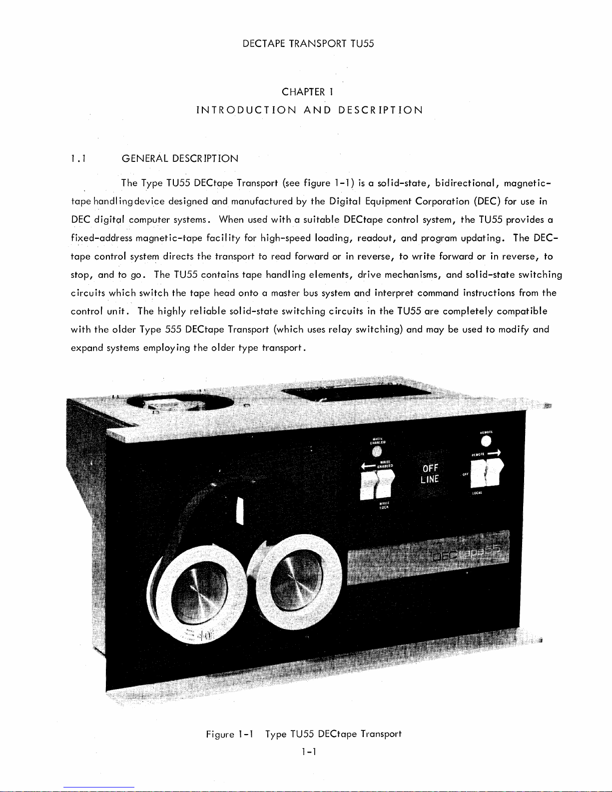
1 .1 GENERAL DESCRIPTION
The
tape
handl ing
DEC
digital
fixed-address
tape
control
stop,
and
to
circuits
control
with
expand
un
the
systems
which
it.
older
Type TU55
device
computer
magnetic-tope
system
go.
directs
The TU55
switch
The
highly
Type
employing
DECtape
designed
systems.
the
tape
rei
555
DECtape
the
and
When
facility
the
transport
contains
head
iable
older
manufactured
sol
Transport
Transport
used
for
tape
(see
witha
high-speed
to
read
handling
onto a master
id-state
switching
(which
type
transport.
AND
figure
by
the
suitable
loading,
forward
elements,
bus system
uses
DESCRIPTION
1-1)
is
a sol
Digital
Equipment
DECtape
readout,
or in
reverse,
drive
and
interpret
circuits
relay
in
the
switching)
id-state,
Corporation
control
and
to
system,
program
write
mechanisms,
command
TU55
are
and
may
bidirectional,
(DEC) for use in
the
TU55
updating.
forward
and
or
solid-state
instructions
completely
be
used
to
magnetic-
provides
The
in
reverse,
switching
from
compatible
modify
a
DEC-
to
the
and
Figure
1-1 Type TU55
1-1
DECtape
Transport
DECT
APE
TRANSPORT TU55
1.2
Transport.
is
given
on
lowing
vited
importance
break
Detailed
TU55
tion
with
1
subsection
to
fam
facility
with a particular
for
the
the
.3
SCOPE
This
instruction
The
equipment
the
operation
contain
Since
the
il
iarize
are
the
in
the
descriptions
TU55
can
transport.
PERTINENT
The
following
OF
MANUAL
of
more
transport
himself
sections
computer;
of
the
computer
be
obtained
DOCUMENTS
documents
manual
is
discussed
its
associated
complete
is
one
with
the
concerning
and
tape
format,
can
is
intended
primarily
element
internal
the
be
from
provide
to
aid
personnel
from a
controls
information
of a computer/control/transport
operations
program
select
instruction
found in
the
interrupts,
and
maintenance
source
maintenance
and
indicators.
on
operation
of
motion
repertoire,
the
user
manual
information
both
programmed
control
handbook
in
the
maintenance
point
of
view,
Pertinent
from a F>rogrammer's
computer
logic
and
progn::lmming
for
for
the
relative
documents I isted
cmd
in/out
in
the
th~~
computer.
DECtape
to
the
of
but
system,
control.
transfers,
external
practice
control
use
of
the
TU55
some
viewpoint.
the
reader
Of
spec
and
DECtape
for
Control
system used
the
DECtape
DECtape
information
in
the
fol-
is
in-
ial
the
data-
control.
using
the
informa-
Trans-
port
Type
TU55:
1
.3.
1
Manuals
Digital
PDP-7
PDP-8
DECtape
DECtape
DECtape
DECtape
DECtape
1
.3.2
are
in
chapter 5 all
Engineering
A
addition
FLIP
User
Handbook,
User
Handbook,
Control
Control
Control
Control
PDP-8
set
of
reduced'
to
the
complete
maintenance
CH
IP
Modu
550
551
552
TCOl
Programming
Drawings
engineering
personnel
les
Catalog,
F-75
F-85
Instruction
Instruct
Instruction
Instruction
set
of
full-size
should
C-105
Manual,
ion
Manual,
Manual,
Manual, H-TC01
Manual,
drawings
Digital-8-27-U
for
drawings
use
only
H-550
H-551
H-552
the
TU55
forwarded
the
full
is
contained
size
engineering
with
eClch
in
chapter
TU55.
drawings
5.
As
explained
for work
These
drawings
in
on
the
equ'ipment
because
these
drawings
show v(Jriations
pecul
1-2
iar
to
an
individuol
installation.
DECT
APE
TRAI'lSPORT TU55
1.3.3
computer
.4
1
five
channels
in
series.
single
contains
of
signal.
tape
New
Module
G850
SCR
Motor
G8S1 Relay
W513
Level Ampl
In
addition
using
DECtape
FUNCTIONAL
The TU55 Transport
of
Thus,
Connections
the
read
motion.
The
left
to
the
O.75-inch
information
and
write
hal f
News
Bulletins
Driver
ifier
the
above
systems.
DESCRIPTION
provides a read/write
tape.
on
one
from
the
amplifiers
of
the
front
documents,
Each
channel
track
combines
read/write
as
well
panel
(see
complete
head
as
the
figure
sets
head
for
consists
with
redundant
are
made
command
1-1)
contains
of
Library Programs
recording
of
two
nonadiace~t
information
directly
logic
for
the
tape
and
to
the
the
are
playback
coils
on
another
external
selection
deck
with
available
of
information
which
are
to
control
and
remote
reels
and
for
wired
create
unit
control
reel
each
on
a
which
motors,
switches
directly
tape
for
control
The
heads.
the
commands
Soliq-state
torque
applied
(i
In
direction
motion
so-called
speed
the
shaft
reel
one
of
is
bidirectional
Manchester
need
diameter
achieves a positive
motor
continues
of
the
two
guides,
selection
tape
logic
.e.,
go,
normal
motion.
not
be a prec
of
the
reel
and
the
and
motion.
circuits
switching
to
each
forward,
tape
movement,
Reduced
so
that
phase
isely
tape
pack
stop
to
apply
brakes
read/write
manual
No
of
the
circuits
reel
motor
reverse,
torque,
either
recording
controlled
on
by
partial
is
appl
head;
operation.
capstans,
TU55 command
completely
to
transport
stop).
full
torque
applied
reel
can
technique
parameter.
the
take-up
braking
ied
the
torque
opposite
to
the
The
pinch
control
is
to
the
serve
rather
reel.
trailing
take
to
the
right
half
600-rpm
rollers,
tape
movement
the
the
tape
appl
ied
trailing
as
the
than
Actua"y,
An
electromagnetic
reel
at
up
tape
direction
is
the
induction
or
drag
tape
across
to
the
reel,
take-up
an
amplitude
the
the
end
slack.
of
local
motors
pads
contact
in
either
drive
the
head
take-up
maintains
reel.
speed
of a motion
Whenever
the
last
control
that
direction
motors.
in
accordance
reel,
proper
The
sensing
varies
brake
tape
panel
with
drive
the
the
tape.
over
These
thus
establ
tape
DECtape
technique;
%
±20
,
mounted
command.
the
tape
movement.
rocker
reel
hubs
the
read/write
circuits
with
govern
specific
ishing
tension.
system uses
thus,
depending
on
each
motor
The
take-up
is
motionless,
the
Tape
the
tape
upon
1-3
the
of
TU55
rocker
Tape
movement
via a suitable
type
switches
is
controlled
DECtape
located
control
on
the
DECT
either
front
APE
TRANSPORT TU55
by
commands
system,
panel
or
by
of
commands
the
transport.
originating
generated
Typical
in
the
computer
through
DECtape
and
manual
control
applied
operation
systems
to
which
Manual
proper
read
or
selector
the
drive
In
local
late
tape
allow
transfer
control
operation
External
write
tape.
at
the
off-I
operation,
motion.
PDP-1,
PDP-6
PDP-5
PDP-8
PDP-9
is
used
of
center
ine
by a
of
information
Computer
-4
and
to
mount
the
control
DECtape
The
operator
of
the
setting
the
head
between
and
-7
-8
new
logic
control
may
TU55
local
on
the
is
disconnected
reels
in
moving
systems
select
control
same
the
computer
Typical
of
tape
on
the
tape.
may
control
the
address
panel
thumbwheel
and
the
the
TU55
up
of
(see
or
rocker
and
the
DECtape
Type
Type
Type
TC01
TC02
or
to
eight
each
figure
by
switching
switches
TU55
Control
550
551
552
as a
individually
drive
1-1).
on
are
quick
by
adjusting
The
the
the
as
follows:
System
maintenance
addressed
the
operator
drive
for
local
control
check
TU55s
thumbwheel
may
also
local
operation.
panel
for
to
place
regu-
1.5
that
allow
Double
are
bay
screws
doors in
mounted
that
contains
at
the
arrangement
extruded
deck
sides
aluminum
and
by
brackets.
control
field.
PHYSICAL DESCRIPTION
All
components
easy
access
the
on
the
The
tape
corners.
preserves
front
rear
the
deck
plates
panel.
Head
of
the
to
the
top,
and
of
the
DECtape
is
machined
Reel
motors,
the
integrity
at
the
The
azimuth
rear
DEC
control
top
head
TU55
sides,
are
is
are
held
bay.
system.
from
tape
of
the
and
is
mounted
set
during
mounted
and
rear
closed
Generally,
3/8-inch
guides
tape
al
bottom
in
manufacture
on a preformed
of
the
drive
by
magnetic
the
cast
aluminum
and
the
head
ignment
front
direct
of
the
contact
by
hold
latches.
transport
are
the
rigidity
chassis
with
of
the
and
the
chassis
is
mounted
plate
secured
serve
the
drive
assembled
in a
Power
supplies
with
cmd
held
only
to
of
the
deck
CIS
bumpers
deck
and
and
cannot
chassis.
standard
others
to
the
the
deck.
plate.
to
protect
is
secured
be
adjusted
Roller
and
in
chassis
slides
DEC
bay.
controls
the
same
by
This
Heavy
the
at
both
in
the
cap
1-4
No
attempt
position.
should
be
DECT
made
to
APE
loosen
TRANSPORT TU55
CAUTION
the
brackets
.
and
change
the
head
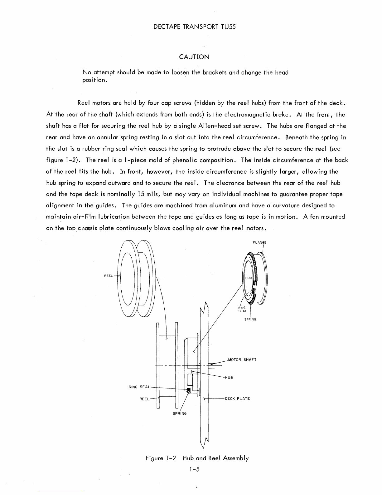
At
the
rear
shaft
has a
rear
and
the
slot
figure
of
hub
and
the
spring
the
1-2).
reel
alignment
maintain
on
the
topchassis
motors
Reel
of
the
flat
for
have
an
is a rubber
The
fits
the
to
expand
tape
deck
in
the
guides.
air-film
are
shaft
(which
securing
annular
reel
spring
ring
seal
is a 1-piece
hub.
In
outward
is
nominally
The
lubrication
plate
continuously
REEL
held
the
which
front,
and
guides
between
by four
extends
reel
hub by a
resting
causes
mold
however,
to
secure
15
mils,
cap
from
in a
of
but
are
machined
the
blows
screws
both
single
slot
the
phenol
the
the
may
tape
cool
ends)
cut
spring
ic
inside
reel.
vary
and
ing
(hidden
by
is
the
Allen-head
into
the
to
protrude
composition.
circumference
The
clearance
on
individual
from
aluminum
guides
air
as
over
the
reel
hubs) from
electromagnetic
set
screw.
reel
circumference.
above
The
the
inside
is
slightly
between
machines
and
have a curvature
long
as
tape
the
reel
motors.
FLANGE
the
brake.
The hubs
Beneath
slot
to
secure
circumference
larger,
the
rear
to
guarantee
is
in
motion.
front
At
the
are
flanged
the
allowing
of
the
designed
A fan
of
the
front,
the
spring
reel
at
the
reel
proper
mounted
deck.
the
at
the
(see
back
the
hub
tape
to
in
RING
SE
A L
REEL
Figure
--rj---+-l--L_
1-2
SPRING
Hub
1-5
and
Reel Assembly
MOTOR
SPRING
SHAFT

DECT
APE
TRANSPORT TU55
matically
control
these
are
type
of
center,
.
while
channels
The
in
figure
information.
the
two
information
where
reading
are
they
takes
separated
redundantly
1-3.
The
tracks
TAPE
DECK
PLATE
in
the
are
place
for
least
sl
ST~~2~~g~1
paired
Three
two
the
data
simultaneously
ightly
tracks
track
timing
mark
channels.
affected
from
the
L___
r---
II
.073"
I M
that
pairs
are
tracks
channel,
by
are
The six
skew.
in
data
"---_
r--
I
t--l
form
the
five
used for
on
the
Since
the
timing
channel
data;
the
outside
contents
tracks
AUGMENTED
for
writing
and
tracks
~~6iH
---------e.J
0.750"
SPACING
.088"
. H r--'i
~
~ ~
_ _ l M
channels
the
remaining
at
opposite
of
which
these
may
mark
channels,
to
allow
~
on
signify
data
take
room for
I
the
head
pairs
slides
to
channels
place
the
additional
I
l
II
-II
I
are
are
of
the
are
in
the
tracks
illustrated
used as
the
tape.
external
grouped
data
for
sche-
timing
Just
control
at
the
channels
the
latter
shielding.
and
inside
the
nectors
assodated
on
Electrical
The
TU55
the
rear
with
the
Details
requires
panel
(figure
DECtape
I
I
I
I
I
I
Figure
the
DEC
1-4).
control
-t--r----
OAr~T
CHI~~
DATA
CHAN
2'---+------..1
DATA
CHA~
MARK
TIMING CHANNEL
1-3
Arrangement
standard
These
system.
+10
dc
levels
Ac power
T I
C"ANNEL
of
DECtape
and
-15
vdc
power
are
normally
(1
05-125v,
Head
levels
provided
60
cps)
I
I
I
I
I
at
the
from
is
connected
terminal-tab
power
suppl ies
at
the
con-
3-
terminal
receptacle
on
the
rear
panel.
1-6
DECTAPE TRANSPORT TU55
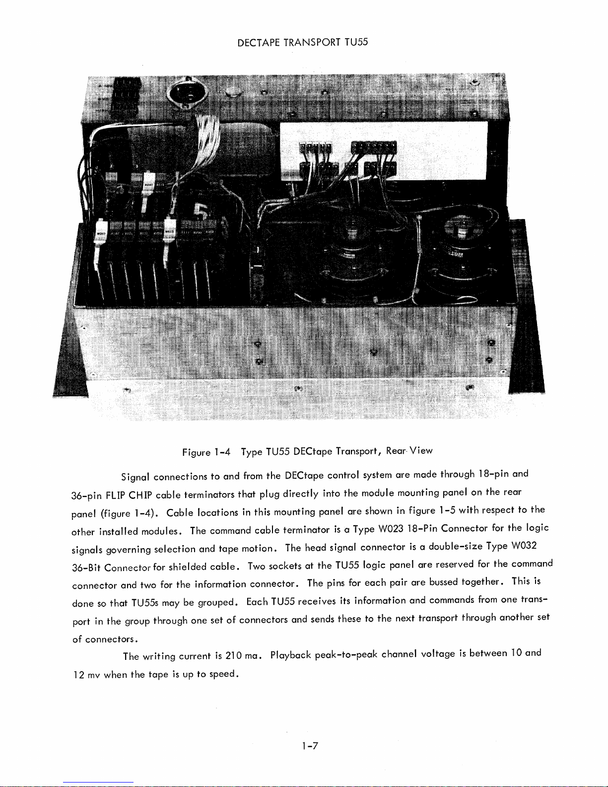
36-pin
panel
other
signals
36-Bit
FLIP
(figure
installed
governing
Connector
connector
done
so
port
in
the
of
connectors.
12
mv
when
Signal
CHIP
and
that
group
The
the
connections
cable
1-4).
Cable
modules.
selection
for
shielded
two for
TU55s may
through
writing
tape
is up
Figure
1-4
to
terminators
locations
The command
and
cable.
the
information
be
grouped.
one
set
current
to
is
speed.
Type TU55 DECtape Transport I Rear-
and
from
the
that
tape
of
connectors
210
plug
in
this
mounting
cable
motion.
Two
sockets
connector.
Each TU55
ma.
Playback
DECtape
directly
terminator
The
and
control
into
panel
is
head
signal
at
the
TU55
The pins for
receives
sends
peak-to-peak
the
are
a Type W023
its
these
system
module
are
mounting
shown in
connector
logic
panel
each
pair
information
to
the
next
channel
View
made
through
panel
figure
18-Pin
1-5
with
Connector
is a double-size
are
reserved
are
bussed
and
commands from
transport
voltage
together.
through
is
18-pin
on
the
respect
for
Type W032
for
the
another
between
and
rear
to
the
logic
command
This
one
trans-
10
and
the
is
set
1-7
DECTAPE TRANSPORT TU55
...J
Wa::
20
<u-
a..U
W
1-2
22
00
a::U
LL
R
303
R
303
2
o
fi
~
a::
a::
i2~
~U
~W
...J2
«2
8
t5
U;
o
«
W
J:
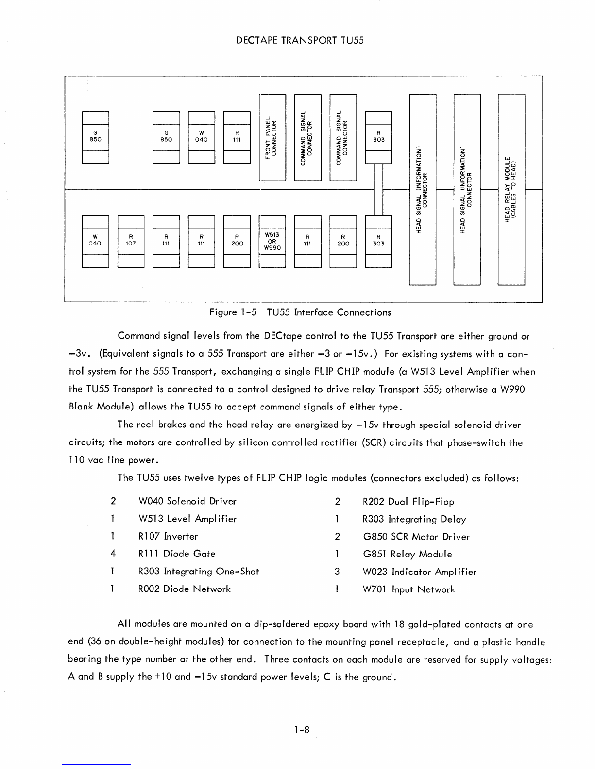
-3v.
trol
system for
the
rU55
Blank
Module)
circuits;
110
vac I ine
Command
(Equivalent
the
Transport
allows
The
reel
the
motors
power.
The TU55 uses
W040
2
W513
1 R
4
R111
R303
R002 Diode
signal
signals
555
is
connected
brakes
are
Solenoid
Level Ampl
107
Inverter
Diode
Integrating
levels
to a 555
Transport,
the
TU55
and
controlled
twelve
Gate
Network
Figure
1-5
from
the
Transport
TU55
DECtape
are
exchanging a single
to
to
the
types
a contr1ol
accept
head
by
silicon
of
designed
command
relay
are
controlled
FLIP CH
Driver
ifier
One-Shot
Interface
control
either
FLIP
to
signals
energized
IP
logic
Connections
to
the
TU55
-3
or
-15v.)
CHIP
drive
of
either
by
rectifier
relay
For
module
Transport
type.
-15v
throu!~h
(SCR)
modules (connec1"ors
2 R202
R303
2
G850
G851
3
W023
W701
Trc::msport
existing
(a
W513
circuits
Duall
Inte!~rating
SCR
RelclY
Indi'cator Ampl
Input
555;
spec
that
excluded)
FI
ip-Flop
Motor
Module
Network
are
either
systems
Level
with a con-
Amplifier
otherwise
ial
solenoid
phase-switch
as follows:
Delay
Driver
ifier
ground
a
W990
driver
the
or
when
All
modules
end
(36
on
double-height
bearing
A
the
type
and B supply
the + 10
number
are
mounted
modules) for
at
the
and
-15v
on a d'ip-soldered
connection
other
end.
standard
Three
power
epoxy
to
the
mounting
contacts
on
levels; C is
1-8
board
each
the
with
panel
modu Ie
ground.
18
gold-plated
receptacle,
are
reserved
contacts
and a plastic
for
supply
at
one
handle
voltages:
DECTAPE TRANSPORT TU55
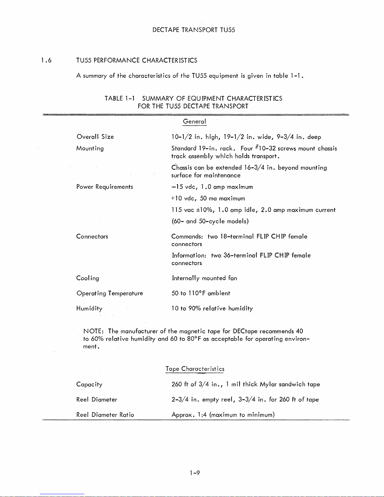
1
.6
TU55
PERFORMANCE CHARACTERISTICS
A summary
Overall
Size
Mounting
Power
Requirements
Connectors
of
the
TABLE
characteristics
1-1
SUMMARY
FOR
THE
of
the
TU55
equ
ipment
OF
EQUIPMENT CHARACTERISTICS
TU55
DECT
APE TRANSPORT
General
10-1/2
Standard
track
C"hassis
surface
in.
high,
19-
in.
assembly
can
be
for
maintenance
rack.
which
extended
-15vdc,l.0ampmaximum
+10
vdc,
50
ma maximum
115
vac
(60-
and
Commands:
%
±10
50-cyc
two
1.0
,
Ie
18-terminal
connectors
Information:
two
connectors
19-1/2
Four
holds
amp
models)
36-term
is
given
in.
transport.
16-3/4
idle,
inal
in
wide,
#10-32
in.
2.0
FLIP
FLIP
table
9-3/4
screws
beyond
amp
CH
CH
1-1 •
in.
maximum
IP
female
IP
female
deep
mount
chassis
mounting
current
Cool
ing
Operating
Humidity
NOTE:
to
60%
ment.
Capacity
Reel
Diameter
Reel
Diameter
Temperature
The
manufacturer
relative
humidity
Ratio
of
and
Tape
Internally
50
to
11
10
to
90% relative
the
magnetic
60
to
80°F
Characteristics
260
ft
2-3/4
Approx
of
in.
•.
O°F
1:4
mounted
ambient
tape
as
acceptable
3/4
in.,
empty
(maximum
fan
humidity
for
DECtape
1 mil
reel,
for
thick
3-3/4
to
minimum)
recommends
operating
Mylar
in.
sandwich
for
260
40
environ-
ft
of
tape
tape
1-9
DECTAPE TRANSPORT TU55
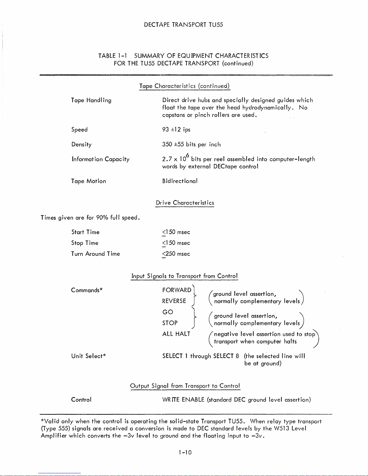
Times
Tape
Speed
Tape
given
Handling
Density
Information
Motion
are
for
90%
TABLE
Capacity
full
1-1
FOR
SUMMARY
THE
speed.
TU55
Tape
OF
EQUIPMENT
DECT APE TRANSPORT
Characterist
Direct
float
capstans
93
350
2.7 x 106 bits
words
Bidirectional
Drive
i cs
(conti
drive
hubs
the
tape
over
or
pinch
±12
ips
±55
bits
per
per
by
external
Chara'cteristics
inch
CHARACTERISTICS
(continued)
nued)
and
specially
the
head
rollers
reel
assembled
DECtape
are
designed
hydrodynamically.
used.
into
control
guides
computer-length
which
No
Start
Time
Stop
Time
Turn
Around
Commands*
Unit
Select*
Control
Time
Input
Output
<150
<150
<250
Signcds
FORWARD}
REVERSE
GO
STOP
ALL
SELECT 1
Signal
WR
msec
msec
msec
to
Transport
HALT
from
ITE
ENABLE
from
}
through
Transport
Control
ground
(
normally
ground
(
normally
negative
transport
(
SELECT 8
to
Control
(standard
level
Clssertion,
complementary
level
,assertion,
complementary
level
assertion
when
computer
(the
selected
be
at
ground)
DEC
ground
level
'\
levels)
)
levels
used
to
halts
line
will
assertion)
stoP'\
)
*Valid
(Type
Amplifier
only
555)
when
signals
which
the
control
are
received a conversion
converts
the
-3v
is
operating
level
the
to
solid-state
is
made
ground
and
1-10
to
DEC
the
Transport
standard
floating
TU55.
levels
input
to
\Nhen
by
,-3v.
relay
the
type
W513
transport
Level

DECT
APE
TRANSPORT TU55
CHAPTER 2
2.1
BLOCK DIAGRAM ANALYSIS
The
trols
and
indicators
controls
tween
and
blocks;
indicators
resents a signal
DECtape
information
A5
"
.-....
~
-
'---'
AB2
"
~
-
~
--
A6
,.........
.-....
...,
ADDRESS
lELECTED
""
STOP
FORWARD~
REVERSE
ALL
'--'
AB3
"
_DATA 1 (4)
,.DATA 3 (4)
'---'
control
signal
(8)
GO
HALT..-
TMG (4)
MRK
(4)
DATA 2 (4)
TU55
an
open
asserted
system.
bus
WRITE
II
..-
~
...,
B
.-....
...,
""
logic
is
are
shown
are
summarized
diamond
at
-3v.
One
to
other
ENABLE
SELECT
LOGIC
REMOTE
SELECT
1 I
SELECT
DELAY
DELAY
----.
BoFf3
LOCAL
MOTION
CONTROL
I
HEAD
RELAY
SELECTED
SKEW MEAS.
_TMG
}t1RK
]lATA 1 (4)
~
]lATA 2 (4)
yATA
r---
----
THEORY
shown in
within
the
the
in
functional
blocks
table
represents a signal
All
interface
of
the
two
connectors
TU55s.
I
WRITE
ENABLED
B
WRITE
LOCK
(1)
0)
MOTION
(0)
DIRECTION (1 )
MOTION
(I)
DIRECTION
(0)
I
(1)
(4)
(4)
3(4)
-
HEAD
-
OF
OPERATION
block
representing
3-1.
Diamonds
effective
signals
are
at
DELAY
(0)
1
TDELAY(I)
~
~ANDl
~ANDI
~GO
~
--
~ANDI
diagram
received
.the
~
.-
-GO
._FWD
.-
AND REV
• -
the
associated
indicate
(asserted)
left
of
figure
1
1._
I
I
of
figure
2-1.
logic.
the
direction
at
ground; a closed
from
or
transmitted
2-1
serves
..-
JAND
1
~-
~ANDI
~-
STOP TORQUE ....
OR
I
l
FULL
DRAG
DRAG
FULL
STOP TORQUE ....
------
~I
~--.J
. -
lOR
--
All front
The
functions
of
signal
to
as a command
RIGHT BRAKE
LEFT
BRAKE
.....
......
.....
.....
..-
.....
......
RIGHT
MOTOR
DRIVER
LEFT
MOTOR
DRIVER
TORQUE ....
TORQUE..-
TORQUE.-.
TORQUE
panel
flow
diamond
an
external
of
con-
these
rep-
and
..
be-
Ir
REEL
RIGHT
LEFT
REEL
NOTE:
head
In
switch
switch
playback,
the
motion
results
is
An
in
arrow
control
in
the
Figure
signifies a nonstandard
brake
block
tape
movement
LOCAL
2-1
voltage,
position.
DECtape
etc.
the
arrow
in
the
Transport TU55 Block Diagram
DEC
signal,
above a switch
indicated
2-1
such
means
direction
as
motor
that
when
voltage,
pressing
the
middle
this
 Loading...