

Digital Equipment TLZ09 Owner's Manual

TLZ09CassetteTapeDrive
Owner’sManual
Order Number: EK-TLZ09-OM. C01
Digital Equipment Corporation
Maynard, Massachusetts

October 1996
Digital Equipment Corporation makes no representations that the use of its products in the
manner described in this publication will not infringe on existing or future patent rights, nor do
the descriptions contained in this publication imply the granting of licenses to make, use, or sell
equipment or software in accordance with the description.
© Digital Equipment Corporation 1996. All rights reserved.
Printed in the U.S.A.
FCC NOTICE: The equipment described in this manual has been certified to comply with
the limits for a Class B computing device, pursuant to Subpart J of Part 15 of FCC Rules.
Only peripherals (computer input/output devices, terminals, printers, et cetera) certified to
comply with the Class B limits may be attached to this computer. Operation with noncertified
peripherals may result in interference to radio and television reception. This equipment
generates and uses radio frequency energy and if not installed and used properly, that is, in
strict accordance with the manufacturer’s instructions, may cause interference to radio and
television reception. It has been type tested and found to comply with the limits for a Class B
computing device in accordance with the specifications in Subpart J of Part 15 of FCC Rules,
which are designed to provide reasonable protection against such interference in a residential
installation. However, there is no guarantee that interference will not occur in a particular
installation. If this equipment does cause interference to radio or television reception, which can
be determined by turning the equipment off and on, the user is encouraged to try to correct the
interference by one or more of the following measures:
• Reorient the receiving antenna.
• Move the computer away from the receiver.
• Plug the computer into a different outlet so computer and receiver are on different branch
circuits.
The following are trademarks of Digital Equipment Corporation: DECdirect, DECmailer,
DECservice, DECstation, Q–bus, SERVICenter, StorageWorks, ULTRIX, VAXstation, VMS, and
the DIGITAL logo.
Novell and NetWare are registered trademarks of Novell, Inc.
Microsoft is a registered trademark and Windows NT is a trademark of Microsoft Corporation.
Sony is a registered trademark of Sony Corporation.
Sun and Solaris are registered trademarks and SunOS is a trademark of Sun Microsystems, Inc.
IBM and AIX are registered trademarks and RS/6000 is a trademark of International Business
Machines Corporation.
Hewlett-Packard and HP-UX are registered trademarks of Hewlett-Packard Company.
S3384
This document was prepared using VAX DOCUMENT Version 2.1.

Für Bundesrepublik Deutschland
For Federal Republic of Germany
Pour la République féderal d’Allemagne
BESCHEINIGUNG DES HERSTELLERS/IMPORTEURS
Dieses Gerät ist in Übereinstimmung mit den Bestimmungen der BMPT Vfg.243/1991 und
Vfg.46/1992 in Verbindung mit EN55022:1987 (DIN VDE 0878-3:11.89), oder Vfg.1046/1984
mit Vfg. 483/1986, funkentstört. Es trägt als Nachweis der EMV-Konformität entweder eine
Konformitätskennzeichnung oder das VDE-Funkschutzzeichen.
Der vorschriftsmäßige Betrieb mancher Geräte (z.B. Meßsender) kann allerdings gewissen
Einschränkungen unterliegen. Beachten Sie deshalb die unten aufgeführten Hinweise.
Für Geräte die nicht mit dem VDE-Funkschutzzeichen versehen sind wurde dem Bundesamt für
Zulassungen in der Telekommunikation (BZT) das Inverkehrbringen dieses Gerätes angezeigt
und die Berechtigung zur Überprüfung der Serie auf Einhaltung der Bestimmungen eingeräumt.
Betreiberhinweis
Wir sind verpflichtet, Sie auf folgende Fakten hinzuweisen (BMPT-Amtsblattverfügung 243/91
bzw. 1046/84 §2, Abschnitt 5):
Dieses Gerät wurde funktechnisch sorgfältig entstört und geprüft. Wird dieses Gerät innerhalb
einer Anlage zusammen mit anderen Geräten betrieben, muß bei Inanspruchnahme der
"Allgemeinen Betriebsgenehmigung" nach BMPT-AmtsblVfg. 243/91 bzw. 1046/84 die gesamte
Anlage den unter §2, Abschnitt 1, genannten Voraussetzungen entsprechen.
Externe Datenkabel
Sollte ein Austausch der von Digital spezifierten Datenkabel nötig werden, muß der Betreiber
für eine einwandfreie Funkentstörung sicherstellen, daß Austauschkabel im Aufbau und
Abschirmqualität dem Digital Originalkabel entsprechen.


Contents
1 TLZ09/9L Cassette Tape Device Product Description
1.1 Overview ........................................... 1–1
1.1.1 System Support ................................... 1–2
1.2 Design Features . . . ................................... 1–2
1.2.1 What is Digital Audio Tape (DAT)? . ................... 1–2
1.2.2 What is Digital Data Storage (DDS)? ................... 1–2
1.2.3 What is the Media Recognition System (MRS)? . .......... 1–3
1.3 TLZ09/9L Models . . ................................... 1–3
1.3.1 Checking Your Shipment for Model TLZ09-DA/DB ........ 1–8
1.3.2 Checking your Shipment for Model TLZ9L-DA/DB ........ 1–8
1.3.3 Ordering Additional Cassettes ........................ 1–9
2 Installing the Tabletop Drive or Autoloader (TLZ09-DA/DB or
TLZ9L-DA/DB)
2.1 General . ........................................... 2–1
2.2 Shut Down, Halt, and Power Off the System ................ 2–1
2.3 Selecting the SCSI Address . . ........................... 2–2
2.4 Connecting a SCSI Signal Cable — Device to System ......... 2–3
2.5 Adding Another Tabletop Device — Device to Device .......... 2–4
2.6 Connecting the Power Cable . ........................... 2–5
3 Installing the TLZ09-AA/AB, -BA/BB Cassette Tape Drive
3.1 General . ........................................... 3–1
3.2 Shut Down, Halt, and Power Off the System ................ 3–1
3.3 Selecting the Jumper and Switch Configuration for the
TLZ09-AA/AB, -BA/BB Drive . ........................... 3–2
3.3.1 SCSI ID Address Jumpers ........................... 3–2
3.3.2 Other Optional Jumper Settings . . . ................... 3–4
3.3.3 Drive Switch Settings . . . ........................... 3–4
3.4 Connecting a SCSI Signal Cable — Drive to System .......... 3–6
v

3.5 Connecting the Power Cable and Mounting . ................ 3–6
4 Verifying TLZ09 Cassette Tape Drive Installation
4.1 General ............................................ 4–1
4.1.1 Execute POST .................................... 4–1
5 Using the TLZ09 Cassette Tape Drive
5.1 General ............................................ 5–1
5.2 Power Switch ........................................ 5–1
5.3 Unload Button ....................................... 5–1
5.4 Tape Drive LEDs ..................................... 5–1
5.4.1 Status LED ...................................... 5–2
5.4.2 TapeLED........................................ 5–2
5.4.3 Busy LED ....................................... 5–2
5.5 Using the Cassette Tape ............................... 5–5
5.5.1 Proper Handling of Cassette Tapes .................... 5–5
5.5.2 Setting the Write-Protect Tab on the Cassette Tape. ....... 5–6
5.5.3 Inserting a Cassette Tape into the Drive ................ 5–7
6 Preventive Maintenance and Problem Solving
6.1 Cleaning the Heads . . . ................................ 6–1
6.2 Problem Solving ...................................... 6–3
6.2.1 System-Based Diagnostics . . . ........................ 6–4
6.3 Repair Services ...................................... 6–4
6.3.1 On-Site Service . . . ................................ 6–4
6.3.2 BASIC Service .................................... 6–5
6.3.3 DECservice ...................................... 6–5
6.3.4 Carry-In Service . . . ................................ 6–5
6.3.5 DECmailer Service . ................................ 6–5
6.3.6 Per Call Service . . . ................................ 6–5
7 Using the TLZ9L Cassette Tape Autoloader
7.1 Overview . . . ........................................ 7–1
7.2 LED Indicators ...................................... 7–2
7.3 LCD Panel . . ........................................ 7–5
7.3.1 Warning Indicator . ................................ 7–6
7.3.2 Write Protect Indicator ............................. 7–7
7.3.3 Error Indicator .................................... 7–8
7.3.4 7-Segment Numeric Display. . ........................ 7–8
vi

7.3.5 Cartridge Number Indicators ......................... 7–8
7.4 TLZ9L Operation . . ................................... 7–9
7.4.1 Automatic Operations . . . ........................... 7–9
7.4.2 Manual Operations ................................ 7–9
7.4.3 Magazine Operations ............................... 7–10
7.4.3.1 Eight Cartridge Mode ........................... 7–10
7.4.3.2 Seven Cartridge Mode ........................... 7–11
7.4.3.3 Single Cartridge Mode ........................... 7–12
7.4.3.4 Loading Cartridges Into the Magazine ............... 7–13
7.4.3.5 Loading the Magazine Into the TLZ9L .............. 7–14
7.4.3.6 Ejecting the Magazine ........................... 7–15
7.4.3.7 Unloading Cartridges From the Magazine . . .......... 7–16
7.5 Switch Settings . . . ................................... 7–17
7.5.1 Switchpack Settings ................................ 7–17
7.5.2 SCSI ID Select Switch (TLZ9L-DA/DB Only) . . . .......... 7–17
7.6 Cleaning Requirements ................................ 7–18
A Cassette Tape Drive and Autoloader Specifications
B Enabling/Disabling Data Compression Under Digital UNIX
and OpenVMS
B.1 Digital UNIX TLZ09 Compression and Noncompression
Modes. . . ........................................... B–1
B.2 Digital UNIX DUMP Utility . ........................... B–1
B.3 OpenVMS TLZ09 Compression and Noncompression Modes . . . . B–2
C Product Notes for Non-Digital Platforms
C.1 Product Notes for Novell NetWare and Microsoft Windows
NT ................................................ C–1
C.1.1 Host SCSI Interface ................................ C–1
C.2 Product Notes for Sun ................................. C–3
C.2.1 General Information................................ C–3
C.2.2 Modifications Required for SunOS 4.1.x ................. C–4
C.2.2.1 Installation Procedure ........................... C–4
C.2.2.2 System Modification . . ........................... C–4
C.2.2.3 Rebuilding of Kernel . ........................... C–5
C.2.2.4 Installation of Tape Drive ........................ C–6
C.2.2.5 Rebooting of System . . ........................... C–6
C.2.2.6 Testing the Tape Drive ........................... C–6
C.2.2.7 Verification . ................................... C–7
vii

C.2.2.8 Dump Parameters for the Tape Drive ............... C–7
C.2.3 Modifications Required for Solaris 2.3 (or later) ........... C–7
C.2.3.1 Installation Procedure . . . ........................ C–7
C.2.3.2 System Modification ............................. C–8
C.2.3.3 System Shutdown .............................. C–9
C.2.3.4 Installation of the Tape Drive ..................... C–9
C.2.3.5 Rebooting of System ............................. C–10
C.2.3.6 Test ......................................... C–11
C.2.3.7 Verification .................................... C–11
C.2.3.8 Dump Parameters for the Tape Drive ............... C–11
C.3 Product Notes for IBM RS/6000 . . ........................ C–12
C.3.1 Modifications Required to Operate the Tape Drive with AIX
3.2.5 (or later) .................................... C–12
C.3.1.1 Installing the Tape Drive Using the SMIT Command . . . C–12
C.3.1.2 Installing the Tape Drive Using Command-Line
Interface...................................... C–13
C.3.2 Using the Tape Drive to Install AIX . . . ................ C–14
C.4 Product Notes for Hewlett-Packard ....................... C–15
C.4.1 General Information................................ C–15
C.4.2 Modifications Required ............................. C–15
C.4.2.1 Installation Procedure . . . ........................ C–16
C.4.2.2 Installation of Tape Drive ........................ C–16
C.4.2.3 System Modification ............................. C–16
C.4.2.4 System Device Files ............................. C–16
C.4.2.5 HP-UX 9.05 . . . ................................ C–17
C.4.2.6 HP-UX 10.x . . . ................................ C–18
C.4.3 Testing the Tape Drive ............................. C–19
C.4.3.1 Verification . . . ................................ C–19
C.4.3.2 Dump Parameters for the Tape Drive ............... C–20
Index
Figures
1–1 Model TLZ09-DA/DB (Tabletop) ....................... 1–4
1–2 Model TLZ09-AA/AB (3.5-inch Chassis) . ................ 1–5
1–3 Model TLZ09-BA/BB (5.25-Inch Chassis) ................ 1–6
1–4 TLZ09 Chassis–Underside with Switch Pack ............. 1–7
3–1 Configuration Jumper Block . ........................ 3–3
3–2 Drive Switch Settings .............................. 3–5
5–1 TLZ09 Cassette Tape ............................... 5–6
viii

7–1 Model TLZ9L-AA (Front and Bottom View) .............. 7–3
7–2 Model TLZ9L-DA/DB (Front and Rear View) . . . .......... 7–4
7–3 TLZ9L LCD Panel ................................. 7–5
7–4 TLZ9L Cassette Magazine ........................... 7–7
7–5 Eight Cartridge Mode . . . ........................... 7–10
7–6 Seven Cartridge Mode . . . ........................... 7–11
7–7 Single Cartridge Mode . . . ........................... 7–12
7–8 Loading Cartridges Into the Magazine .................. 7–13
7–9 Loading the Magazine Into the TLZ9L-DA/DB . .......... 7–14
7–10 Unloading Cartridges From the Magazine ............... 7–16
Tables
3–1 SCSI ID Jumper Settings (0=Removed, 1=Installed) ....... 3–3
5–1 TLZ09 LED Status ................................. 5–2
6–1 Problem Solving ................................... 6–3
7–1 BUSY and TAPE LEDs Status ........................ 7–2
7–2 Warning Indications ................................ 7–6
7–3 Error Indications .................................. 7–8
7–4 Switchpack Settings ................................ 7–17
A–1 TLZ09 Cassette Tape Drive Specifications ............... A–1
A–2 TLZ09 Cassette Tape Drive Dimensions ................ A–2
A–3 TLZ09-DA Noise Declaration ......................... A–3
A–4 TLZ9L Cassette Tape Autoloader Specifications . .......... A–4
A–5 TLZ9L Cassette Tape Autoloader Dimensions . . .......... A–5
A–6 TLZ9L-DA/DB Noise Declaration . . . ................... A–6
ix


TLZ09/9L Cassette Tape Device Product
1.1 Overview
The TLZ09/9L Digital Audio Tape (DAT) device provides you with high
capacity, off-line data storage. Depending on the 4 mm data cassette tape used,
the unit can typically store the following amount of data on each tape:
Tape Type (NOTES 1 and 2) No Compression Compression
TLZ04-CA (60 m, DDS-1) 1.3 GB 2.6 GB (see Note 3.)
TLZ06-CA (90 m, DDS-1) 2.0 GB 4.0 GB (see Note 3.)
TLZ07-CA (120 m, DDS-2) 4.0 GB 8.0 GB (see Note 3.)
1. The TLZ09/9L is compatible with 60 m cassette tapes written on the
TLZ04 in the noncompressed mode only.
2. The TLZ09/9L is compatible with the TLZ06/6L using 60 m and 90
m tapes only, and with the TLZ07/7L using 60 m, 90 m, and 120 m
tapes.
3. The compression measurements are typical for a 2-to-1 data
compression ratio, but the actual ratio is dependent on the data.
1
Description
NOTE
The maximum time to back up (read or write) on a TLZ09/9L cassette tape
in a continual (streaming) mode is system dependent. The efficient use of
streaming mode is determined by your operating system. Please refer to your
system software documentation.
TLZ09/9L Cassette Tape Device Product Description 1–1

1.1.1 System Support
As of this printing, the TLZ09/9L device is supported by a variety of Digital
systems. Consult your Digital Sales Support representative for a list of
supported systems. Your particular system must have an available standard
SCSI (Small Computer System Interconnect) port in order to connect the
TLZ09 or TLZ9L.
1.2 Design Features
The TLZ09/9L cassette tape device uses state of the art technology. The
device’s design incorporates the Digital Data Storage (DDS) recording format
and Digital Audio Tape (DAT) recording technologies. It is also designed to
provide a transfer rate that is twice that of standard DDS-2 DAT drives while
still maintaining full DDS compatibility.
1.2.1 What is Digital Audio Tape (DAT)?
DAT technology provides a high recording density with a very low error rate
through the helical scan recording method. With this method of recording,
both the tape and the recording head move simultaneously. The read and write
heads are located on a rapidly rotating cylinder, or drum that is tilted at an
angle in relation to the vertical axis of the tape. This causes the tracks to be
recorded diagonally across the tape, resulting in an extremely high recording
density, far higher than what is achievable with stationary-head devices.
1.2.2 What is Digital Data Storage (DDS)?
DDS uses a recording format that supports the use of digital audio tape
for computer applications. The objectives of DDS are to maximize storage
capacity and performance, facilitate data interchange, and provide very fast
random access. In addition, this format has three levels of error correction,
which ensures high data integrity. The DDS-DC format, which is a superset
of the basic DDS DAT format, allows you to back up 8 gigabytes of data in
approximately 1.5 hours minimum with no operator intervention, assuming 2:1
compression ratio.
Use of non-DDS media may result in degraded drive performance and
is not recommended by Digital Equipment Corporation.
1–2 TLZ09/9L Cassette Tape Device Product Description
NOTE

1.2.3 What is the Media Recognition System (MRS)?
MRS refers to a series of alternate opaque and clear stripes at the beginning
of a tape. This striping is used to classify the media as data grade rather than
audio grade media. Use of MRS helps to ensure that only data grade tapes are
used in computer applications. All 120-meter cartridges support MRS. Shorter
media are available in both MRS and non-MRS types.
1.3 TLZ09/9L Models
The TLZ09 drive is available in several configurations:
• Model TLZ09-DA/DB (tabletop) — a compact external unit with a built-in
power supply and fan (Figure 1–1).
• Model TLZ09-AA/AB — a 3 1/2-inch, half-height drive that mounts
internally (Figure 1–2 and Figure 1–4).
• Model TLZ09-BA/BB—a31/2-inch drive in a 5 1/4-inch, half-height
form factor allowing the drive to be mounted internally (Figure 1–3 and
Figure 1–4).
• Model TLZ09-VA — a TLZ09-AA mounted in a 3 1/2-inch StorageWorks
SBB.
• Model TLZ09-AX — a field spare unit that is configurable to an -AA, -AB,
-BA, or -BB model. Includes bezel and rail installation procedures.
All the models have a drive buffer size of 1 MB of memory.
The TLZ9L autoloader is available in several configurations:
• Model TLZ9L-AA — a 5 1/4-inch, full-height autoloader that mounts
internally (Figure 7–1). This unit comes with a light gray (DEC 217) bezel
installed and a dark gray (DEC 277) bezel in the shipping carton, along
with bezel removal/mounting procedures.
• Model TLZ9L-DA/DB (tabletop) — an external unit with a built-in power
supply and fan (Figure 7–2).
• Model TLZ9L-VA/VB — a TLZ9L-AA mounted in a 5 1/4-inch StorageWorks
SBB.
NOTE
TLZ09/9L Cassette Tape Device Product Description 1–3
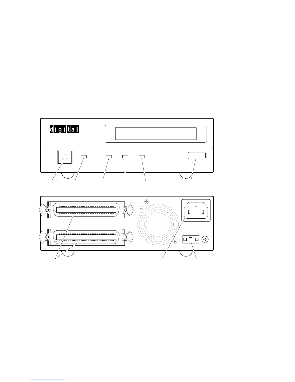
Figure 1–1 Model TLZ09-DA/DB (Tabletop)
On/Off
Switch
Power On
LED
SCSI CONNECTOR
Busy
LED
Tape
LED
Status
LED
SCSI Connectors AC Power
Recepticle
Eject/Unload
Button
AC IN
+-
0
SCSI ID GND
SCSI ID
Indicator/Switch
MLO-011795
1–4 TLZ09/9L Cassette Tape Device Product Description
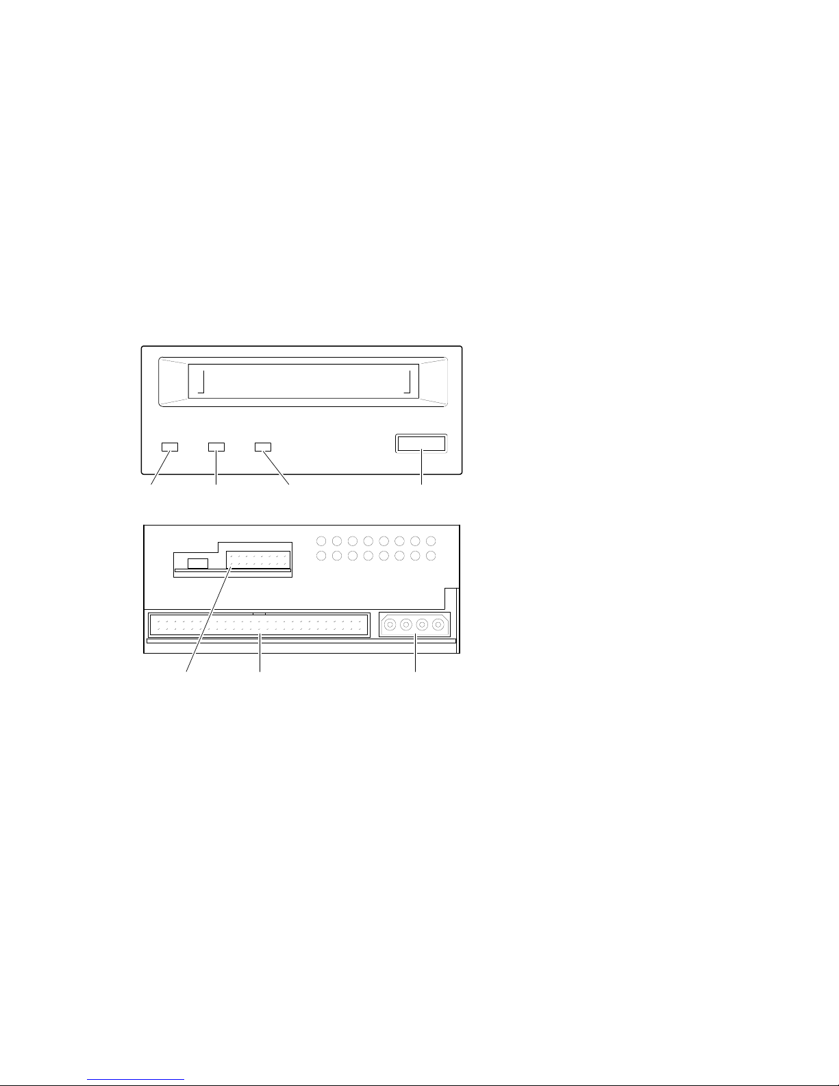
Figure 1–2 Model TLZ09-AA/AB (3.5-inch Chassis)
Busy
LED
Configuration
Jumper Block
Tape
LED
SCSI
Connector
Status
LED
Eject/Unload
Button
DC Power
Connector
MLO-011796
TLZ09/9L Cassette Tape Device Product Description 1–5
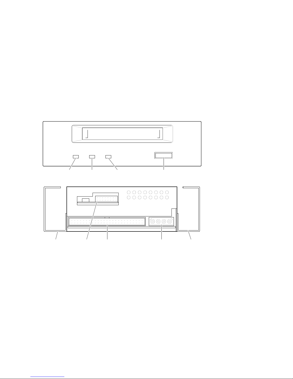
Figure 1–3 Model TLZ09-BA/BB (5.25-Inch Chassis)
5.25" Side
Mounting Rails
Busy
LED
Configuration
Jumper Block
Tape
LED
SCSI
Connector
Status
LED
Eject/Unload
Button
DC Power
Connector
5.25" Side
Mounting Rails
MLO-011797
1–6 TLZ09/9L Cassette Tape Device Product Description
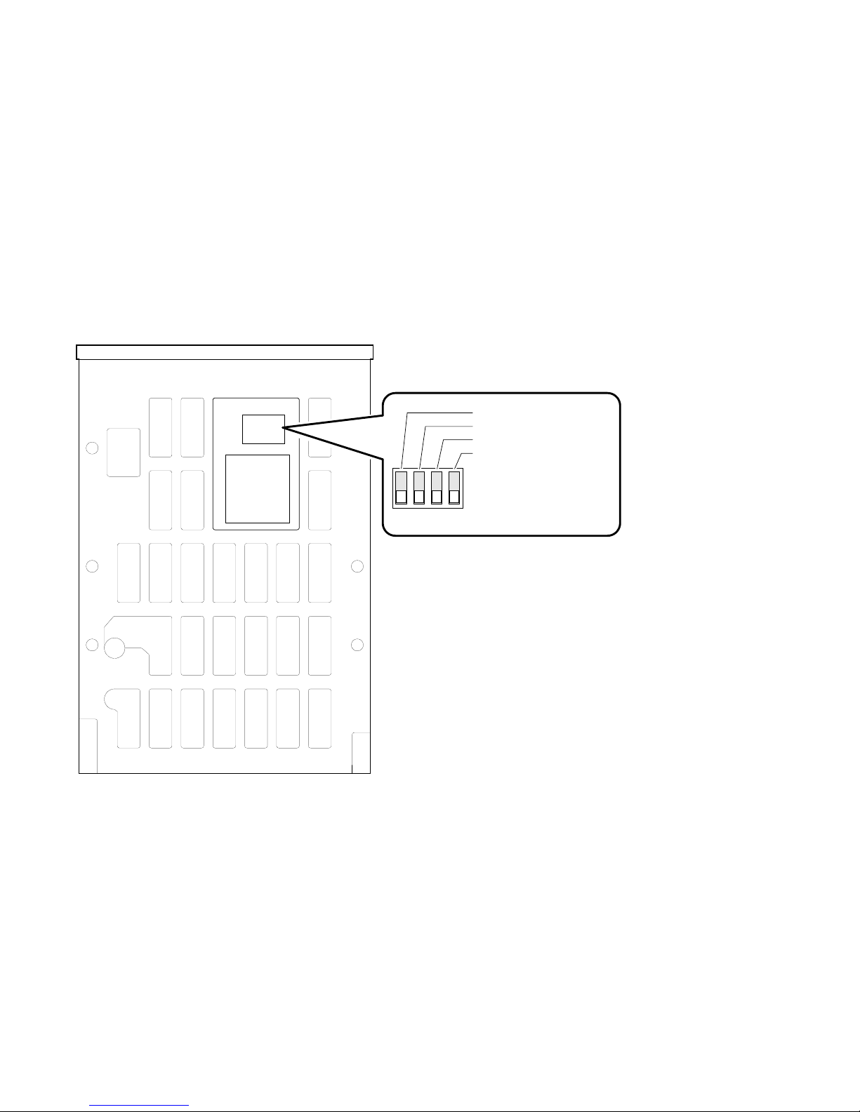
Figure 1–4 TLZ09 Chassis–Underside with Switch Pack
1234
Drive Mode TLZ09 (Off)
MRS Detect Disabled (Off)
Self Test Enabled (Off)
Reserved (Off)
On
Off
MLO-011799
TLZ09/9L Cassette Tape Device Product Description 1–7

1.3.1 Checking Your Shipment for Model TLZ09-DA/DB
In addition to this manual, make sure that your shipment includes the
following:
• One TLZ09-DA/DB tabletop cassette tape drive
• One 50-pin to 50-pin (low density to high density connector) SCSI signal
cable for drive to system connections. PN 17-04356-01 is frost white
and is packaged with the TLZ09-DB, while PN 17-03742-09 is gray and
is packaged with the TLZ09-DA. In the future, black cables may be
substituted for both of these variations.
• AC power cable
• One blank cassette tape (4 mm x 120 m), (PN TLZ07-CA)
• One head cleaning cassette (PN TLZ04-HA)
• Active SCSI terminator [PN 12-44026-01 (frost white) or PN 12-41807-01
(gray)]. In the future, black terminators may be substituted.
If your shipment is incomplete, please contact your Digital sales representative.
1.3.2 Checking your Shipment for Model TLZ9L-DA/DB
In addition to this manual, make sure that your shipment includes the
following:
• One TLZ9L-DA/DB tabletop autoloader
• One 50-pin to 50-pin (low density to high density) SCSI signal cable for
drive to system connections. PN 17-04356-01 is shipped at present, but
may be replaced with a black cable in the future.
• AC power cable
• Eight blank cassette tapes (4 mm x 120 m, PN TLZ07-CA) preloaded in an
eight-slot tape cassette magazine (PN TLZ9L-08)
• One head cleaning cassette tape (PN TLZ04-HA)
• Active SCSI terminator. PN 12-44026-01 is shipped at present, but may be
replaced with a black terminator in the future.
If your shipment is incomplete, please contact your Digital sales representative.
1–8 TLZ09/9L Cassette Tape Device Product Description

1.3.3 Ordering Additional Cassettes
To order additional blank cassette tapes and head cleaning cassettes, contact
your Digital sales representative or DECdirect. Refer to the following part
numbers.
• Five blank cassette tapes (4 mm x 60 m) (PN TLZ04-CB)
• Five blank cassette tapes (4 mm x 90m) (PN TLZ06-CB)
• Five blank cassette tapes (4 mm x 120m) (PN TLZ07-CB)
• One head cleaning cassette (PN TLZ04-HA)
TLZ09/9L Cassette Tape Device Product Description 1–9


2
Installing the Tabletop Drive or Autoloader
(TLZ09-DA/DB or TLZ9L-DA/DB)
2.1 General
This chapter shows you how to install the TLZ09-DA/DB tabletop cassette
tape drive or TLZ9L-DA/DB tabletop cassette tape autoloader on systems
with an external SCSI connector. Read the following sections to complete the
installation.
2.2 Shut Down, Halt, and Power Off the System
If you are installing a TLZ09-DA/DB tabletop cassette tape drive or a TLZ9LDA/DB tabletop cassette tape autoloader on a running system, have your
system manager perform the following steps:
1. Shut down the operating system.
2. Halt the system.
3. Set all system power switches off.
Installing the Tabletop Drive or Autoloader (TLZ09-DA/DB or TLZ9L-DA/DB) 2–1

2.3 Selecting the SCSI Address
To familiarize yourself with the TLZ09 drive and TLZ9L autoloader:
1. Refer to Figure 1–1 for the location of the buttons, switches, and connectors
on the tabletop drive and to Figure 7–2 for the location of the buttons,
switches, and connectors on the tabletop autoloader.
2. Note that all connections are made at the rear of the tabletop enclosure.
Your system uses a SCSI ID switch to identify, or address, the drive. The SCSI
ID is factory set at 0. If you are installing the drive on a system that is already
using SCSI ID 0, use any available SCSI ID. (You may have to consult your
system manager.)
To set/change the SCSI address:
1. Locate the SCSI address switch at the rear of the tabletop enclosure.
2. Select the SCSI address for the drive or autoloader. Press the + or button until the desired address (0 through 7) appears in the window. See
Figure 1–1 for the drive and Figure 7–2 for the autoloader.
If you are installing any other drive variant, refer to Chapter 3.
Turn off all power before connecting the cables and the terminator.
The drive must be turned off and then on for switch settings to take
effect, or a SCSI bus reset must be received.
NOTE
2–2 Installing the Tabletop Drive or Autoloader (TLZ09-DA/DB or TLZ9L-DA/DB)

The tabletop devices provide two SCSI connectors to allow daisy chaining.
Either connector can connect to the host computer or any SCSI device in a
daisy chain.
• If the tabletop is the last device in the chain an interface cable is attached
to one connector and an active SCSI terminator is installed in the other
connector.
• If the device is within the chain, the interface cable from the preceding
device is connected in one connector; an interface cable is also connected
from the other connector to the following device.
NOTE
Make sure that the last SCSI device on the bus is terminated correctly
and is jumpered to supply termination power
2.4 Connecting a SCSI Signal Cable — Device to System
If you are connecting a TLZ09-DA/DB drive or TLZ9L-DA/DB
autoloader directly to your system, you should use the SCSI signal
cable supplied as part of your system installation kit.
If you do not have this cable, contact your Digital sales representative. You
should use a cable supplied by Digital Equipment Corporation. Failure to do
so can result in degraded performance of your tabletop device.
To connect a SCSI cable — device to system — perform the following:
1. Connect one end of the cable to the system SCSI connector.
2. Connect the other end of the SCSI signal cable to either SCSI connector on
the rear of the TLZ09-DA/DB drive or TLZ9L-DA/DB autoloader.
3. Secure the SCSI cable by snapping the wire cable clamps (on either side of
the SCSI connector) into place.
4. Connect the SCSI terminator to the other SCSI connector on the rear of
the TLZ09-DA/DB drive or TLZ9L-DA/DB autoloader.
5. Secure the terminator by snapping the wire cable clamps (on either side of
the SCSI connector) into place.
Installing the Tabletop Drive or Autoloader (TLZ09-DA/DB or TLZ9L-DA/DB) 2–3

2.5 Adding Another Tabletop Device — Device to Device
If you have one SCSI tabletop device already connected to your system, you
can connect the TLZ09-DA/DB drive or the TLZ9L-DA/DB autoloader to that
device. For device to device connections, use a 50-pin low density to 50-pin low
density SCSI signal cable [PN 17-03926-02 (gray), 17-04370-01 (frost white), or
equivalent].
Care should be taken to ensure that total SCSI cable length is well within the
SCSI specification limit of 6 meters for 5 MB/s transfer speeds (including cable
length within the system enclosure). When operating at FAST SCSI (10 MB/s)
transfer speeds, the total cable length must not exceed 3 meters. It is also
important to ensure that the drive is configured to supply terminator power to
the bus (default configuration). See Chapter 3 or Chapter 7 for jumper/switch
configurations.
1. If present, remove the SCSI terminator from the existing SCSI drive.
2. Connect one end of the SCSI signal cable (see part numbers above) to
the existing SCSI device, observing the correct orientation of the cable
connector.
3. Secure the SCSI cable by snapping the wire cable clamps (on either side of
the SCSI connector) into place.
4. Connect the other end of the SCSI signal cable to either SCSI connector on
the TLZ09-DA/DB drive or TLZ9L-DA/DB autoloader, observing the correct
orientation of the cable connector.
5. Secure the SCSI cable by snapping the wire cable clamps (on either side of
the SCSI connector) into place.
6. Connect the SCSI terminator to the other SCSI connector on the TLZ09DA/DB drive or TLZ9L-DA/DB autoloader, observing the correct orientation
of the cable connector.
2–4 Installing the Tabletop Drive or Autoloader (TLZ09-DA/DB or TLZ9L-DA/DB)

2.6 Connecting the Power Cable
The tabletop devices have an autoranging power supply. Refer to Table A–1 or
Table A–4 for voltage specifications.
To connect the power cable, proceed as follows:
1. Be sure that the TLZ09-DA/DB drive or TLZ9L-DA/DB autoloader power
switch is off (0).
2. Connect the power cable to the TLZ09-DA/DB drive or TLZ9L-DA/DB
autoloader power connector.
3. Connect the other end of the power cable to a nearby ac outlet.
Multivendor Customer Services personnel: The power cable disconnects
the device from the main ac power source.
Proceed to Chapter 4.
NOTE
Installing the Tabletop Drive or Autoloader (TLZ09-DA/DB or TLZ9L-DA/DB) 2–5


Installing the TLZ09-AA/AB, -BA/BB
Cassette Tape Drive
3.1 General
This chapter shows you how to install the TLZ09-AA/AB 3.5-inch and TLZ09BA/BB 5.25-inch form factor) cassette tape drives in a system enclosure
or external expansion box. Read the following sections to complete the
installation.
3.2 Shut Down, Halt, and Power Off the System
If you are installing a TLZ09 drive on a running system, have your system
manager perform the following steps:
1. Shut down the operating system.
2. Halt the system.
3. Set all system power switches off.
3
Installing the TLZ09-AA/AB, -BA/BB Cassette Tape Drive 3–1

3.3 Selecting the Jumper and Switch Configuration for the
TLZ09-AA/AB, -BA/BB Drive
To familiarize yourself with the TLZ09 drive:
1. Refer to Figures 1–2 through 1–4 for the location of the buttons, switches,
and connectors on the TLZ09 drive.
2. Note that all connections are made at the rear of the drive.
3.3.1 SCSI ID Address Jumpers
Your system uses a SCSI ID jumper block to identify, or address, the TLZ09.
The SCSI ID is factory set at 0. If you are installing the TLZ09 on a system
that is already using SCSI ID 0, use any available SCSI ID. (You may have to
consult your system manager.)
To set/change the SCSI address, refer to Figure 1–2 and Figure 3–1 for jumper
block location, then:
1. Refer to Figure 3–1 for jumper configuration.
2. Select a unique address number with the first three jumpers on the left.
Table 3–1 shows the SCSI IDs (0 through 7) and Figure 3–1 shows a close-up
view of the jumpers.
NOTE
If you are installing the tabletop variant, refer to Chapter 2.
Turn off all power before connecting the cables.
The drive must be power cycled for switch settings to take effect, or a
SCSI bus reset must be received.
Make sure that both ends of the SCSI bus are terminated correctly. For
the drive, termination is enabled by installing a jumper on pins 13 and
14 of the jumper block.
3–2 Installing the TLZ09-AA/AB, -BA/BB Cassette Tape Drive
NOTE
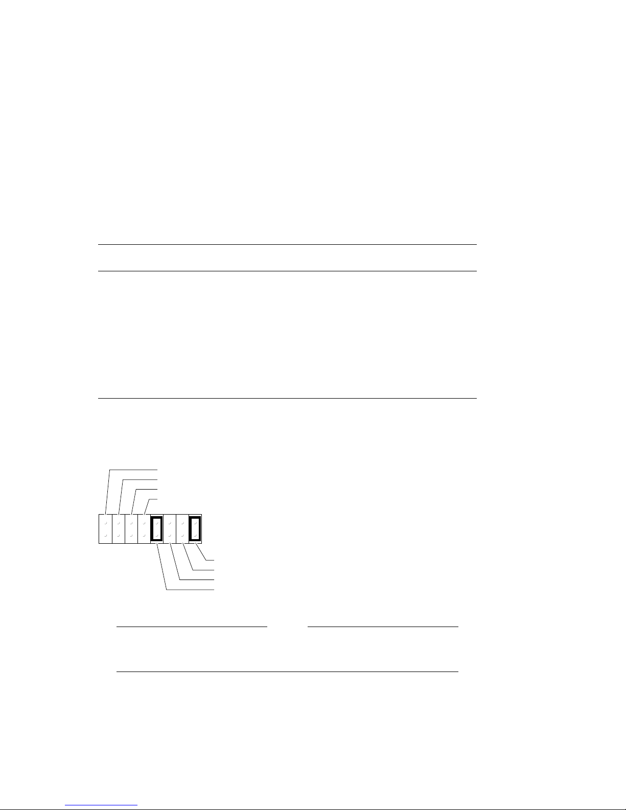
Table 3–1 SCSI ID Jumper Settings (0=Removed, 1=Installed)
SCSI ID
and 2
0 0 0 0 (default setting)
1001
2010
3011
4100
5101
6110
7111
Pins 1
Pins 3
and 4 Pins 5 and 6
Figure 3–1 Configuration Jumper Block
SCSI ID 2
SCSI ID 1
SCSI ID 0
Data Compression Enabled
13579111315
2 4 6 8 10 12 14 16
The drive must be powered down and then powered up for new jumper
settings to take effect.
Terminator Power Enabled
Termination Disabled
Reserved
SCSI Parity Enabled
MLO-011798
NOTE
Installing the TLZ09-AA/AB, -BA/BB Cassette Tape Drive 3–3

3.3.2 Other Optional Jumper Settings
The remaining jumpers allow you to set up the following configuration options:
• Parity enable/disable (jumper 9–10): Default = parity enabled (jumper
installed on pins 9–10)
• Compression enable/disable at power up (jumper 7–8): Default =
compression enabled at power up (jumper removed from pins 7–8)
• Termination enable/disable (jumper 13–14): Default = termination disabled
(jumper removed from pins 13–14)
• Terminator power enable/disable (jumper 15–16): Default = terminator
power enabled (jumper installed on pins 15–16)
Figure 3–1 shows the default settings for these jumpers.
The drive must be turned off and then on for switch settings to take
effect, or a SCSI bus reset must be received.
Although jumper 7–8 is removed by default (compression enabled),
you may turn compression on and off with a software switch. Consult
Appendix B or Appendix C for the command format.
3.3.3 Drive Switch Settings
The drive switch (see Figure 3–2) allows you to configure the following options:
NOTE
• Drive Mode (S1): Switch defaults to off for TLZ09 mode (on indicates
generic mode)
• Media Recognition System Detect Enable/Disable (S2): Switch defaults to
off for no MRS detection.
• Self-Test Enable/Disable (S3): Switch defaults to off to enable diagnostic
self-test a power-up and reset.
• Reserved (S4): This switch is reserved and should be in the off position.
3–4 Installing the TLZ09-AA/AB, -BA/BB Cassette Tape Drive
 Loading...