

Digital Equipment TLZ06 Owner's Manual

TLZ06CassetteTapeDrive
Owner’sManual
Order Number: EK-TLZ06-OM. 004
Digital Equipment Corporation

July 1993
The information in this document is subject to change without notice and should not be
construed as a commitment by Digital Equipment Corporation. Digital Equipment Corporation
assumes no responsibility for any errors that may appear in this document.
No responsibility is assumed for the use or reliability of software on equipment that is not
supplied by Digital Equipment Corporation or its affiliated companies.
Restricted Rights: Use, duplication, or disclosure by the U.S. Government is subject to
restrictions as set forth in subparagraph (c)(1)(ii) of the Rights in Technical Data and Computer
Software clause at DFARS 252.227-7013.
© Digital Equipment Corporation 1993.
All Rights Reserved.
Printed in the U.S.A.
FCC NOTICE: The equipment described in this manual has been certified to comply with
the limits for a Class B computing device, pursuant to Subpart J of Part 15 of FCC Rules.
Only peripherals (computer input/output devices, terminals, printers, et cetera) certified to
comply with the Class B limits may be attached to this computer. Operation with noncertified
peripherals may result in interference to radio and television reception. This equipment
generates and uses radio frequency energy and if not installed and used properly, that is, in
strict accordance with the manufacturer’s instructions, may cause interference to radio and
television reception. It has been type tested and found to comply with the limits for a Class B
computing device in accordance with the specifications in Subpart J of Part 15 of FCC Rules,
which are designed to provide reasonable protection against such interference in a residential
installation. However, there is no guarantee that interference will not occur in a particular
installation. If this equipment does cause interference to radio or television reception, which can
be determined by turning the equipment off and on, the user is encouraged to try to correct the
interference by one or more of the following measures:
• Reorient the receiving antenna.
• Move the computer away from the receiver.
• Plug the computer into a different outlet so computer and receiver are on different branch
circuits.
If necessary, the user should consult the dealer or an experienced radio/television technician
for additional suggestions. The user may find the following booklet prepared by the Federal
Communications Commission helpful: How to Identify and Resolve Radio-TV Interference
Problems. This booklet is available from the US Government Printing Office, Washington, DC
20402, Stock No. 004-000-00398-5.
The following are trademarks of Digital Equipment Corporation: DECdirect, DECmailer,
DECservice, DECstation, Q–bus, SERVICenter, ULTRIX, VAXstation, VMS, and the
DIGITAL logo.
Für Bundesrepublik Deutschland
For Federal Republic of Germany
Pour la République féderal d’Allemagne
BESCHEINIGUNG DES HERSTELLERS/IMPORTEURS
Dieses Gerät ist in Übereinstimmung mit den Bestimmungen der BMPT Vfg.243/1991 und
Vfg.46/1992 in Verbindung mit EN55022:1987 (DIN VDE 0878-3:11.89), oder Vfg.1046/1984
mit Vfg. 483/1986, funkentstört. Es trägt als Nachweis der EMV-Konformität entweder eine
Konformitätskennzeichnung oder das VDE-Funkschutzzeichen.
Der vorschriftsmäßige Betrieb mancher Geräte (z.B. Meßsender) kann allerdings gewissen
Einschränkungen unterliegen. Beachten Sie deshalb die unten aufgeführten Hinweise.
Für Geräte die nicht mit dem VDE-Funkschutzzeichen versehen sind wurde dem Bundesamt für
Zulassungen in der Telekommunikation (BZT) das Inverkehrbringen dieses Gerätes angezeigt
und die Berechtigung zur Überprüfung der Serie auf Einhaltung der Bestimmungen eingeräumt.
Betreiberhinweis
Wir sind verpflichtet, Sie auf folgende Fakten hinzuweisen (BMPT-Amtsblattverfügung 243/91
bzw. 1046/84 §2, Abschnitt 5):
Dieses Gerät wurde funktechnisch sorgfältig entstört und geprüft. Wird dieses Gerät innerhalb
einer Anlage zusammen mit anderen Geräten betrieben, muß bei Inanspruchnahme der
"Allgemeinen Betriebsgenehmigung" nach BMPT-AmtsblVfg. 243/91 bzw. 1046/84 die gesamte
Anlage den unter §2, Abschnitt 1, genannten Voraussetzungen entsprechen.
Externe Datenkabel
Sollte ein Austausch der von Digital spezifierten Datenkabel nötig werden, muß der Betreiber
für eine einwandfreie Funkentstörung sicherstellen, daß Austauschkabel im Aufbau und
Abschirmqualität dem Digital Originalkabel entsprechen.


Contents
1 TLZ06 Cassette Tape Drive Product Description
1.1 Overview ........................................... 1–1
1.1.1 System Support ................................... 1–2
1.2 Design Features . . . ................................... 1–2
1.2.1 What is Digital Audio Tape (DAT)? . ................... 1–2
1.2.2 What is Digital Data Storage (DDS)? ................... 1–2
1.3 TLZ06 Models ....................................... 1–3
1.3.1 Checking Your Shipment for Model TLZ06-DA . .......... 1–6
1.3.2 Ordering Additional Cassettes ........................ 1–6
2 Installing the Tabletop Drives
2.1 General . ........................................... 2–1
2.2 Shut Down, Halt, and Power Off the System ................ 2–1
2.3 Selecting the SCSI Address . . ........................... 2–2
2.4 Connecting a SCSI Signal Cable — Drive to System .......... 2–3
2.5 Adding Another Tabletop Drive — Drive to Drive . . .......... 2–4
2.6 Connecting the Power Cable . ........................... 2–4
3 Installing the TLZ06-AA/BA Cassette Tape Drive
3.1 General . ........................................... 3–1
3.2 Shut Down, Halt, and Power Off the System ................ 3–1
3.3 Selecting the SCSI Address for the TLZ06-AA/BA Drive ....... 3–2
3.3.1 Other Optional Switch Settings ....................... 3–4
3.4 Connecting a SCSI Signal Cable — Drive to System .......... 3–5
3.5 Connecting the Power Cable and Mounting ................. 3–5
v

4 Verifying TLZ06 Cassette Tape Drive Installation
4.1 General ............................................ 4–1
4.1.1 POST . . . ........................................ 4–1
5 Using the TLZ06 Cassette Tape Drive
5.1 General ............................................ 5–1
5.2 Power Switch ........................................ 5–1
5.3 Unload Button ....................................... 5–1
5.4 Write-Protect LED .................................... 5–1
5.5 Cassette LED ........................................ 5–1
5.6 TLZ06 Cassette Tape . . ................................ 5–2
5.7 Indicators . . . ........................................ 5–2
5.8 Using the Cassette Tape ............................... 5–4
5.8.1 Proper Handling of Cassette Tapes .................... 5–4
5.8.2 Setting the Write-Protect Tab on the Cassette Tape. ....... 5–5
5.8.3 Inserting a Cassette Tape into the Drive ................ 5–5
6 Preventive Maintenance and Problem Solving
6.1 Cleaning the Heads . . . ................................ 6–1
6.2 Problem Solving ...................................... 6–3
6.2.1 System-Based Diagnostics . . . ........................ 6–4
6.3 Repair Services ...................................... 6–4
6.3.1 On-Site Service . . . ................................ 6–4
6.3.2 BASIC Service .................................... 6–4
6.3.3 DECservice ...................................... 6–5
6.3.4 Carry-In Service . . . ................................ 6–5
6.3.5 DECmailer Service . ................................ 6–5
6.3.6 Per Call Service . . . ................................ 6–5
7 TLZ6L Auto Loader
7.1 Overview . . . ........................................ 7–1
7.2 Indicators . . . ........................................ 7–1
7.3 Dot Matrix Display . . . ................................ 7–5
7.3.1 Activity Messages . ................................ 7–5
7.3.2 Status Messages . . . ................................ 7–5
7.4 Operation . . . ........................................ 7–6
7.4.1 Automatic Operations .............................. 7–6
7.4.2 Manual Operations ................................ 7–6
7.4.3 Single Cassette Operation . . . ........................ 7–7
vi

7.5 Switch Settings . . . ................................... 7–7
7.5.1 Switchpack 1 . . ................................... 7–7
7.5.2 Switchpack 2 . . ................................... 7–8
7.6 Routine Maintenance .................................. 7–9
7.6.1 Cleaning the Rollers................................ 7–9
7.6.2 Cleaning the TLZ06 Tape Drive ....................... 7–9
A Cassette Tape Drive Specifications
B Enabling/Disabling Data Compression Under ULTRIX and
VMS
B.1 ULTRIX TLZ06 Compression and Noncompression Modes ...... B–1
B.2 ULTRIX DUMP Utility ................................ B–1
B.3 VMS TLZ06 Compression and Noncompression Modes ........ B–2
Index
Figures
1–1 Model TLZ06-DA (Tabletop) .......................... 1–4
1–2 Model TLZ06-AA (3 ½-inch Chassis) and TLZ06-BA (5
¼-inch Form Factor) ............................... 1–5
3–1 SCSI Address Switches . . ........................... 3–3
5–1 TLZ06 Cassette Tape ............................... 5–2
7–1 Model TLZ6L-AA, Front View ........................ 7–2
7–2 Model TLZ6L-AA, Top View .......................... 7–2
7–3 Model TLZ6L-DA, Front View ........................ 7–3
7–4 Model TLZ6L-DA, Back View......................... 7–4
Tables
3–1 SCSI ID Switch Settings (0=Up, 1=Down) ............... 3–3
5–1 TLZ06 LED Status ................................. 5–3
6–1 Problem Solving ................................... 6–3
7–1 Status Messages ................................... 7–5
7–2 SW1 Settings and Functions ......................... 7–7
7–3 SW1-1 and SW1-2 Settings .......................... 7–8
7–4 SW2 Settings and Functions ......................... 7–8
vii

A–1 TLZ06 Cassette Tape Drive Specifications ............... A–1
A–2 TLZ06-DA Noise Declaration . ........................ A–2
A–3 TLZ6L Cassette Tape Drive Specifications ............... A–3
A–4 TLZ6L-DA Noise Declaration . ........................ A–4
viii

TLZ06 Cassette Tape Drive Product
1.1 Overview
The TLZ06 cassette tape drive provides you with high capacity, off-line data
storage. Depending on the 4 mm data cassette tape used, the unit can typically
store:
Tape Type (see NOTE 1.) No Compression Compression
TLZ04-CA (60 m) 1.3 GB 2.6 GB
TLZ06-CA (90 m) 2.0 GB 4.0 GB (see NOTE 2.)
1. The TLZ06 is compatible with TLZ04 (60 m) cassette tapes in the
noncompressed mode only.
2. The 4.0 GB measurement is typical for a 2-to-1 data compression
ratio, but the actual ratio is dependent on the data.
1
Description
NOTE
The maximum time to backup (read or write) on a TLZ06 cassette tape in a
continual (streaming) mode is system dependent. The efficient use of streaming
mode is determined by your operating system. Please refer to your system
software documentation.
TLZ06 Cassette Tape Drive Product Description 1–1

1.1.1 System Support
As of this printing, the TLZ06 drive is supported by VAXstation systems and
DECstation systems. Your particular system must have a standard SCSI
(small computer system interconnect) port, or a KZQSA (Q–bus to SCSI
adapter).
VAXstation systems can use the VMS or ULTRIX operating systems.
DECstation systems use the ULTRIX operating system. Consult with your
Digital sales support person for operating systems supporting this device.
1.2 Design Features
The TLZ06 cassette tape drive uses state of the art technology. The TLZ06
cassette tape drive’s design incorporates both digital data storage (DDS) and
digital audio tape (DAT) recording technologies.
1.2.1 What is Digital Audio Tape (DAT)?
Digital audio tape (DAT), such as TLZ06 cassettes, takes advantage of the
TLZ06 tape drive’s helical scan technology. This technology allows data to
be stored diagonally on tape. As such, DAT allows more data to be stored on
tape. Also, DAT recording minimizes ‘‘crosstalk,’’ providing you with more data
integrity.
1.2.2 What is Digital Data Storage (DDS)?
Digital data storage (DDS) uses a recording format that supports the use of
digital audio tape for computer applications. The DDS/DAT format allows
you to back up 2 gigabytes of data in approximately 3 hours minimum with
no operator intervention. In addition, this format has three levels of error
correction, which ensures high data integrity.
Use of Non-DDS media may result in degraded drive performance and
is not recommended by Digital Equipment Corporation.
1–2 TLZ06 Cassette Tape Drive Product Description
NOTE

1.3 TLZ06 Models
The TLZ06 drive is available as:
• Model TLZ06-DA (tabletop) — a compact external unit with a built-in
power supply (Figure 1–1).
• Model TLZ06-AA — a 3 1/2-inch, half-height drive that mounts internally
(Figure 1–2).
• Model TLZ06-BA — consists of a 3 1/2-inch drive in a 5 1/4-inch, halfheight form factor allowing the drive to be mounted internally (Figure 1–2).
• Model TLZ6L-AA—a51/4-inch, full-height auto loader that mounts
internally (Figure 7–1).
• Model TLZ6L-DA (tabletop) — an external unit with a built-in power
supply.
All the models have a drive buffer size of 1 MB of memory.
NOTE
TLZ06 Cassette Tape Drive Product Description 1–3
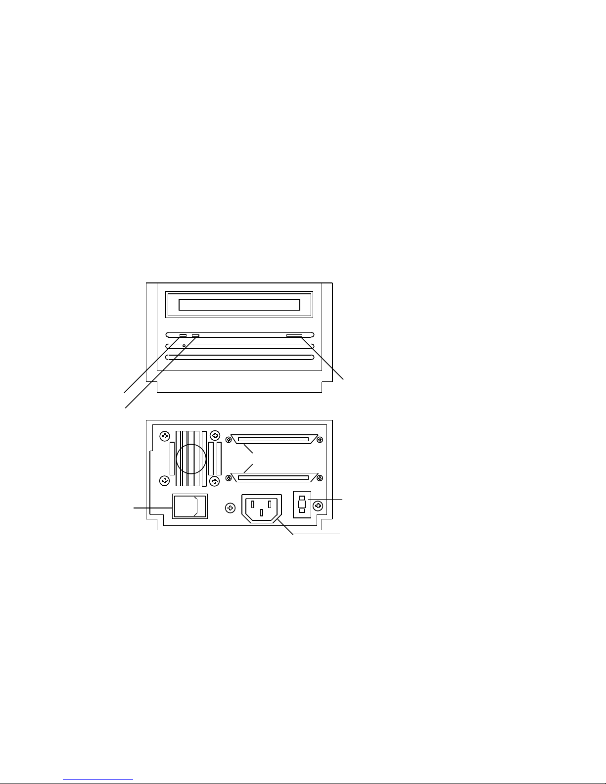
Figure 1–1 Model TLZ06-DA (Tabletop)
Front View
Power On
Indicator
Tape/Activity
Indicator
Write Protect
Indicator
Rear View
SCSI Connectors
Tape Unload
Button
On/Off Switch
0
1–4 TLZ06 Cassette Tape Drive Product Description
−
5
+
SCSI ID Switch
Power Connector
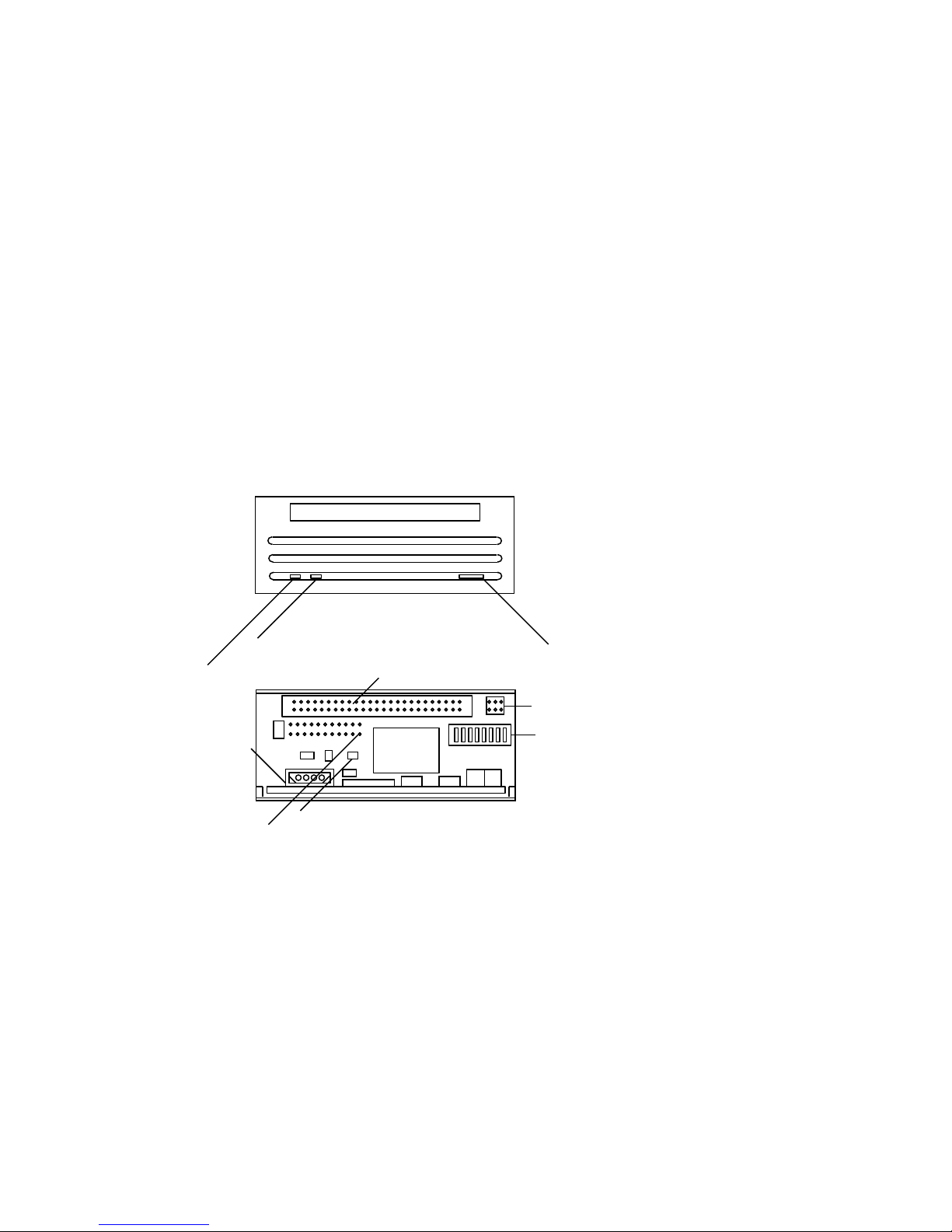
Figure 1–2 Model TLZ06-AA (3 ½-inch Chassis) and TLZ06-BA (5 ¼-inch
Form Factor)
Front View
Write Protect
Tape/Activity Indicator
Power Connector
Terminator Resistor
Pack Sockets
(Place Pin 1 here)
50
Term Power
SCSI Connector
JP4
U2
Rear View
Tape Unload
Tape Unload
Tape Unload
Tape Unload
Tape Unload
Tape Unload
Button
Button
Button
Button
Button
Button
SW
3 2 1
2
Remote ID Pins
SCSI ID and
SW1
Option Switch
(refer to text for
switch settings)
TLZ06 Cassette Tape Drive Product Description 1–5

1.3.1 Checking Your Shipment for Model TLZ06-DA
In addition to this manual, make sure that your shipment includes the
following:
• One TLZ06-DA tabletop cassette tape drive
• One 50-pin to 50-pin SCSI signal cable (PN 17-01351-01) for drive to drive
connections only
• Power cable
• One blank cassette tape (4 mm x 90 m), (PN TLZ06-CA)
• One head cleaning cassette (PN TLZ04-HA)
• SCSI terminator (PN 12-30552-01)
If your shipment is incomplete, please contact your Digital sales representative.
1.3.2 Ordering Additional Cassettes
To order additional blank cassette tapes and head cleaning cassettes, contact
your Digital sales representative or DECdirect. Refer to the following part
numbers.
• Five blank cassette tapes (4 mm x 60 m) (PN TLZ04-CB)
• Five blank cassette tapes (4 mm x 90m) (PN TLZ06-CB)
• One head cleaning cassette (PN TLZ04-HA)
1–6 TLZ06 Cassette Tape Drive Product Description

Installing the Tabletop Drives
2.1 General
This chapter shows you how to install the TLZ06-DA tabletop cassette tape
drive or TLZ6L-DA tabletop auto loader on systems with an external SCSI
connector. Read the following sections to complete the installation.
2.2 Shut Down, Halt, and Power Off the System
If you are installing a TLZ06-DA tabletop cassette tape drive or TLZ6L-DA
tabletop auto loader on a running system, have your system manager perform
the following steps:
1. Shut down the operating system.
2. Halt the system.
3. Set all system power switches off.
2
Installing the Tabletop Drives 2–1

2.3 Selecting the SCSI Address
To familiarize yourself with the TLZ06 drive:
1. Refer to Figure 1–1 for the location of the buttons, switches, and connectors
on the tabletop drives.
2. Note that all connections are made at the rear of the drive.
Your system uses a SCSI ID switch (Figure 1–1) to identify, or address, the
drive. The SCSI ID is factory set at 5. If you are installing the drive on a
system that is already using SCSI ID 5, use any available SCSI ID. (You may
have to consult your system manager.)
To set/change the SCSI address:
1. Locate the SCSI address switch at the rear of the drive.
2. Select the SCSI address for the drive:
• TLZ06-DA — Press the + or - button until the desired address (0
through 7) appears in the window.
• TLZ6L-DA — Set the switches according to Table 3–1.
If you are installing any other drive variant, refer to Chapter 3.
Turn off all power before connecting the cables and the terminator.
The drive must be turned off and then on for switch settings to take
effect, or a SCSI bus reset must be received.
NOTE
2–2 Installing the Tabletop Drives

The tabletop drives provide two SCSI connectors to allow daisy chaining.
Either connector can connect to the host computer or any SCSI device in a
daisy chain.
• If the tabletop is the last drive in the chain, a single interface cable is
attached to one connector and a SCSI terminator (PN 12-30552-01) is
installed in the other connector.
• If the drive is within the chain, the interface cable from the preceding
device is connected in one connector; an interface cable is also connected
from the other connector to the following device.
NOTE
Make sure that the last SCSI device on the bus is terminated correctly.
2.4 Connecting a SCSI Signal Cable — Drive to System
If you are connecting a TLZ06-DA drive or TLZ6L-DA auto loader
directly to your system, you should use the SCSI signal cable supplied
as part of your system installation kit.
If you do not have this cable, contact your Digital sales representative. You
should use a cable supplied by Digital Equipment Corporation. Failure to do
so can result in degraded performance of your tabletop drive.
To connect a SCSI cable — drive to system — perform the following:
1. Connect one end of the cable to the system SCSI connector.
2. Connect the other end of the SCSI signal cable to either SCSI connector on
the rear of the TLZ06-DA drive or TLZ6L-DA auto loader.
3. Secure the SCSI cable by snapping the wire cable clamps (on either side of
the SCSI connector) into place.
4. Connect the SCSI terminator to the other SCSI connector on the rear of
the TLZ06-DA drive or TLZ6L-DA auto loader.
5. Secure the terminator by snapping the wire cable clamps (on either side of
the SCSI connector) into place.
Installing the Tabletop Drives 2–3
 Loading...