

Digital Equipment StorageWorks HSZ70 Configuration Manual
DIGITAL StorageWorks
HSZ70 Array Controller
HSOF Version 7. 0
EK–HSZ70–CG. A01
Digital Equipment Corporation
Maynard, Massachusetts
Confi guratio n Manual

July 1997
While D ig ital Equi pment C or p or ation bel i eve s th e in fo rmatio n inc l u d ed in th is manual is correct as of the d at e of
public ation , i t is sub je ct to cha nge wit hout no tice . DI GITAL mak es no r epr esent at i ons tha t t he in terco nne ct ion of it s
product s in the manner described in this document will not infringe exi sting or future patent rights, nor do the
descriptions contained in this document imply the granting of licenses to make, use, or sell equipment or software
in acc ordance with the description. No responsibility is assumed for the use or r eliability of firmwar e on equipment
not suppl ied by DIGITAL or its af filiated com panies. Posses sion, use, or copying of the softwa re or firmware
described in this documentation is authorized only pursuant to a valid written license from DIGITAL, an authorized
sublic ensor, or t h e identifie d licensor.
Commercia l Comp uter Sof twa re, Co mput er Softw ar e Doc umentat i on and Techni ca l Da ta for Commer ci al I tems ar e
licens ed to the U.S. Government with DI G ITAL’s standar d com mercial license and, when applicable, the rights in
DFAR 252.227 7015, “Techn ical Data—Commercial Items.”
© Digital Equipment Corporation, 1997.
Printed in U.S.A.
All rights reserv ed.
DIGITAL, DIGITAL UNIX, DECconnect, HSZ, StorageWorks, VMS, OpenVMS, and the DIGITAL logo are
trademarks of Digital Equipment Corporat ion.
UNIX is a regi st ered tr ad emar k in th e Unite d Sta te s and othe r cou ntr ies ex cl usive ly t hro ugh X/ Open Comp any Lt d.
Windows NT is a trademark of the Microsoft Corporation. Su n is a registered trademark of Sun Microsy stems, Inc.
Hewlett-Packard and HP–UX are registered trademarks of the Hewlett-Packard Company . IBM and AIX are
registered trademarks of International Business Machines Corporation. All ot her trademarks and registered
trademarks are the property of their respective owners.
This e quipment has been teste d and found to comply wit h the limits for a Class A digital device, pursuant to Part 15
of th e FCC Rules. These limits are designed to pro vide reasonable protection against harmful int erference when the
equipment is operated in a commercial environment . This equipment generates, use s and can radiate radio frequency energy and, if not installed a nd used in accordance with the manuals, may cause harm ful interference to
radio co mmunications. O p eration of this equipment in a residential area is likely to cause harmful interference in
which case the user will be required to correct the interference at his own expense. Restrictions apply to the use of
the loca l-connection port on this ser ies of controll ers; failure to observe these restricti ons may result in harmful
interference. Always disconnect this port as soon as possible after completing the setup operation. Any changes or
modifications made to this equipment may void the user's authority to operate the equipme nt.
Warning!
This is a Class A product. In a domestic environment this product may cause radi o interference in which case the
user may be required to take adequate measures.
Achtung!
Dieses i st ein Gerät der Funkstörgrenzwertklasse A. In Wohnbereichen können bei Betrieb dieses Ge rätes Rundfunkstörungen auftreten, in welchen Fällen der Benutzer für entsprechende Gegenmaßnahmen verantwortlich ist.
Avertissement!
Cet appar eil est un appareil de Classe A. Dans un environnement résidentiel cet appareil peut provoquer des brouillages r adioélectriq ues. Dans ce cas, il peut être demandé à l’ utilisateur de prendre les mesures appropriées.

Contents
iii
Figures . . . . . . . . . . . . . . . . . . . . . . . . . . . . . . . . . . . . . . . . . . . . . . . . . . . . . . . . . . .vii
T ables . . . . . . . . . . . . . . . . . . . . . . . . . . . . . . . . . . . . . . . . . . . . . . . . . . . . . . . . . . . viii
Preface
Precautions. . . . . . . . . . . . . . . . . . . . . . . . . . . . . . . . . . . . . . . . . . . . . . . . . . . . . . . . .x
Electrostatic Discharge Precautions . . . . . . . . . . . . . . . . . . . . . . . . . . . . . . . . . .x
VHDCI Cable Precautions . . . . . . . . . . . . . . . . . . . . . . . . . . . . . . . . . . . . . . . . xi
Local-Connection Port Precautions . . . . . . . . . . . . . . . . . . . . . . . . . . . . . . . . . xi
Conventions . . . . . . . . . . . . . . . . . . . . . . . . . . . . . . . . . . . . . . . . . . . . . . . . . . . . . . .xii
T ypographical Conventions . . . . . . . . . . . . . . . . . . . . . . . . . . . . . . . . . . . . . . .xii
Special Notices . . . . . . . . . . . . . . . . . . . . . . . . . . . . . . . . . . . . . . . . . . . . . . . . xiii
Required Tools . . . . . . . . . . . . . . . . . . . . . . . . . . . . . . . . . . . . . . . . . . . . . . . . . . . . xiv
Related Publications. . . . . . . . . . . . . . . . . . . . . . . . . . . . . . . . . . . . . . . . . . . . . . . . .xv
Revision History. . . . . . . . . . . . . . . . . . . . . . . . . . . . . . . . . . . . . . . . . . . . . . . . . . . xvi
Introduction
Features of Your Controller . . . . . . . . . . . . . . . . . . . . . . . . . . . . . . . . . . . . . . . . . . 1-2
Controller Com ponents . . . . . . . . . . . . . . . . . . . . . . . . . . . . . . . . . . . . . . . . . . . . . 1-6
Key Steps for Configuring Your Subsystem . . . . . . . . . . . . . . . . . . . . . . . . . . . . . 1-7
Configuring an HSZ70 Array Controller
Introduction . . . . . . . . . . . . . . . . . . . . . . . . . . . . . . . . . . . . . . . . . . . . . . . . . . . . . . 2-2
Configuration Rules . . . . . . . . . . . . . . . . . . . . . . . . . . . . . . . . . . . . . . . . . . . . 2-2
Configuring a Controller . . . . . . . . . . . . . . . . . . . . . . . . . . . . . . . . . . . . . . . . . . . . 2-3
Setting the PVA Module ID Switch . . . . . . . . . . . . . . . . . . . . . . . . . . . . . . . . 2-6
Establishing a Local Connection to the Controller. . . . . . . . . . . . . . . . . . . . . 2-7
Selecting a Failover Mode . . . . . . . . . . . . . . . . . . . . . . . . . . . . . . . . . . . . . . . 2-9
Selecting a Cache Mode . . . . . . . . . . . . . . . . . . . . . . . . . . . . . . . . . . . . . . . . 2-10

iv Configuration Manual
Setting SCSI Target ID Numbers. . . . . . . . . . . . . . . . . . . . . . . . . . . . . . . . . 2-18
Enabling Mirrored Write-Back Cache . . . . . . . . . . . . . . . . . . . . . . . . . . . . . 2-19
Using Preferred ID Numbers . . . . . . . . . . . . . . . . . . . . . . . . . . . . . . . . . . . . 2-19
Changing the CLI Prompt . . . . . . . . . . . . . . . . . . . . . . . . . . . . . . . . . . . . . . 2-20
Setting the Maximum Data-Transfer Rate. . . . . . . . . . . . . . . . . . . . . . . . . . 2-20
Backing up Power with a UPS. . . . . . . . . . . . . . . . . . . . . . . . . . . . . . . . . . . 2-20
Selecting a Host Compatibility Mode . . . . . . . . . . . . . . . . . . . . . . . . . . . . . 2-21
Connecting a Controller to the Host . . . . . . . . . . . . . . . . . . . . . . . . . . . . . . 2-21
Planning Storagesets
Creating a Storageset and Device Profile . . . . . . . . . . . . . . . . . . . . . . . . . . . . . . . 3-2
Determining Storage Requirements . . . . . . . . . . . . . . . . . . . . . . . . . . . . . . . . . . . 3-4
Choosing a Storag es et Type . . . . . . . . . . . . . . . . . . . . . . . . . . . . . . . . . . . . . . . . . 3-5
Using Stripesets to Increase I/O Performance. . . . . . . . . . . . . . . . . . . . . . . . . . . . 3-6
Considerations for Planning a Stripeset. . . . . . . . . . . . . . . . . . . . . . . . . . . . . 3-7
Using Mirrorsets to Ensure Availability . . . . . . . . . . . . . . . . . . . . . . . . . . . . . . . . 3-9
Considerations for Planning a Mirrorset . . . . . . . . . . . . . . . . . . . . . . . . . . . . 3-9
Using RAIDsets to Increase Performance and Availability . . . . . . . . . . . . . . . . 3-12
Considerations for Planning a RAIDset. . . . . . . . . . . . . . . . . . . . . . . . . . . . 3-13
Using Striped Mirrorsets for Highest Performance and Availability . . . . . . . . . 3-15
Considerations for Planning a Striped Mirrorset . . . . . . . . . . . . . . . . . . . . . 3-15
Naming Storagesets and Units . . . . . . . . . . . . . . . . . . . . . . . . . . . . . . . . . . . . . . 3-16
Assigning Unit Numbers for Host Access to Storagesets . . . . . . . . . . . . . . . . . . 3-17
Creating a Storageset Map . . . . . . . . . . . . . . . . . . . . . . . . . . . . . . . . . . . . . . . . . 3-19
Device PTL Addressing Convention within the Controller. . . . . . . . . . . . . 3-20
Planning Partitions . . . . . . . . . . . . . . . . . . . . . . . . . . . . . . . . . . . . . . . . . . . . . . . 3-24
Defining a Partition . . . . . . . . . . . . . . . . . . . . . . . . . . . . . . . . . . . . . . . . . . . 3-24
Guidelines for Partitioning Storagesets and Disk Drives. . . . . . . . . . . . . . . 3-25
Choosing Switches for Storagesets and Devices. . . . . . . . . . . . . . . . . . . . . . . . . 3-26
Enabling Switches . . . . . . . . . . . . . . . . . . . . . . . . . . . . . . . . . . . . . . . . . . . . 3-26
Changing Switches. . . . . . . . . . . . . . . . . . . . . . . . . . . . . . . . . . . . . . . . . . . . 3-26
RAIDset Switches . . . . . . . . . . . . . . . . . . . . . . . . . . . . . . . . . . . . . . . . . . . . . . . . 3-27
Replacement Policy . . . . . . . . . . . . . . . . . . . . . . . . . . . . . . . . . . . . . . . . . . . 3-27
Reconstruction Policy . . . . . . . . . . . . . . . . . . . . . . . . . . . . . . . . . . . . . . . . . 3-27
Membership . . . . . . . . . . . . . . . . . . . . . . . . . . . . . . . . . . . . . . . . . . . . . . . . . 3-28
Mirrorset Switches . . . . . . . . . . . . . . . . . . . . . . . . . . . . . . . . . . . . . . . . . . . . . . . 3-29

Replacement Policy . . . . . . . . . . . . . . . . . . . . . . . . . . . . . . . . . . . . . . . . . . . 3-29
Copy Speed . . . . . . . . . . . . . . . . . . . . . . . . . . . . . . . . . . . . . . . . . . . . . . . . . . 3-29
Read Source . . . . . . . . . . . . . . . . . . . . . . . . . . . . . . . . . . . . . . . . . . . . . . . . . 3-30
Device Switches. . . . . . . . . . . . . . . . . . . . . . . . . . . . . . . . . . . . . . . . . . . . . . . . . . 3-31
Transportability. . . . . . . . . . . . . . . . . . . . . . . . . . . . . . . . . . . . . . . . . . . . . . . 3-31
Transfer Rate. . . . . . . . . . . . . . . . . . . . . . . . . . . . . . . . . . . . . . . . . . . . . . . . . 3-32
Initialize Switches . . . . . . . . . . . . . . . . . . . . . . . . . . . . . . . . . . . . . . . . . . . . . . . . 3-33
Chunk Size . . . . . . . . . . . . . . . . . . . . . . . . . . . . . . . . . . . . . . . . . . . . . . . . . . 3-33
Save Configuration . . . . . . . . . . . . . . . . . . . . . . . . . . . . . . . . . . . . . . . . . . . . 3-36
Destroy/Retain . . . . . . . . . . . . . . . . . . . . . . . . . . . . . . . . . . . . . . . . . . . . . . . 3-38
Unit Switches. . . . . . . . . . . . . . . . . . . . . . . . . . . . . . . . . . . . . . . . . . . . . . . . . . . . 3-40
Access Protection . . . . . . . . . . . . . . . . . . . . . . . . . . . . . . . . . . . . . . . . . . . . . 3-40
Partition. . . . . . . . . . . . . . . . . . . . . . . . . . . . . . . . . . . . . . . . . . . . . . . . . . . . . 3-41
Maximum Cache Transfer . . . . . . . . . . . . . . . . . . . . . . . . . . . . . . . . . . . . . . 3-41
Preferred Path for Multiple-Bus Failover Configurations . . . . . . . . . . . . . . 3-42
Read Cache . . . . . . . . . . . . . . . . . . . . . . . . . . . . . . . . . . . . . . . . . . . . . . . . . . 3-42
Availability . . . . . . . . . . . . . . . . . . . . . . . . . . . . . . . . . . . . . . . . . . . . . . . . . . 3-42
Write Protection . . . . . . . . . . . . . . . . . . . . . . . . . . . . . . . . . . . . . . . . . . . . . . 3-43
Write-back Cache . . . . . . . . . . . . . . . . . . . . . . . . . . . . . . . . . . . . . . . . . . . . . 3-43
Moving Storagesets . . . . . . . . . . . . . . . . . . . . . . . . . . . . . . . . . . . . . . . . . . . . . . . 3-44
The Next Step... . . . . . . . . . . . . . . . . . . . . . . . . . . . . . . . . . . . . . . . . . . . . . . . . . . 3-47
v
Configuring Storagesets
Manually Configuring Storagesets. . . . . . . . . . . . . . . . . . . . . . . . . . . . . . . . . . . . . 4-2
Adding Disk Drives . . . . . . . . . . . . . . . . . . . . . . . . . . . . . . . . . . . . . . . . . . . . 4-2
Configuring a Stripeset . . . . . . . . . . . . . . . . . . . . . . . . . . . . . . . . . . . . . . . . . . 4-2
Configuring a Mirrorset . . . . . . . . . . . . . . . . . . . . . . . . . . . . . . . . . . . . . . . . . 4-4
Configuring a RAIDset. . . . . . . . . . . . . . . . . . . . . . . . . . . . . . . . . . . . . . . . . . 4-6
Configuring a Striped Mirrorset . . . . . . . . . . . . . . . . . . . . . . . . . . . . . . . . . . . 4-8
Configuring a Single-Disk Unit . . . . . . . . . . . . . . . . . . . . . . . . . . . . . . . . . . 4-10
Configuring a Tape Drive . . . . . . . . . . . . . . . . . . . . . . . . . . . . . . . . . . . . . . . 4-12
Configuring a Tape Loader . . . . . . . . . . . . . . . . . . . . . . . . . . . . . . . . . . . . . . 4-13
Partitioning a Storageset or Disk Drive . . . . . . . . . . . . . . . . . . . . . . . . . . . . 4-14
Adding a Disk Drive to the Spareset. . . . . . . . . . . . . . . . . . . . . . . . . . . . . . . 4-16
Removing a Disk Drive from the Spareset . . . . . . . . . . . . . . . . . . . . . . . . . . 4-17
Enabling Autospare. . . . . . . . . . . . . . . . . . . . . . . . . . . . . . . . . . . . . . . . . . . . 4-18

vi Configuration Manual
Deleting a Storageset . . . . . . . . . . . . . . . . . . . . . . . . . . . . . . . . . . . . . . . . . . 4-18
Changing Switches for a Storageset or Device . . . . . . . . . . . . . . . . . . . . . . 4-19
Automatically Configuring Storagesets with CFMENU. . . . . . . . . . . . . . . . . . . 4-21
Considerations for Using CFMENU . . . . . . . . . . . . . . . . . . . . . . . . . . . . . . 4-23
Adding Disk Drives with CFMENU . . . . . . . . . . . . . . . . . . . . . . . . . . . . . . 4-23
Creating a Storageset with CFMENU . . . . . . . . . . . . . . . . . . . . . . . . . . . . . 4-24
Deleting a Storageset with CFMENU . . . . . . . . . . . . . . . . . . . . . . . . . . . . . 4-25
Adding a Disk Drive to the Spareset with CFMENU . . . . . . . . . . . . . . . . . 4-26
Partitioning a Storageset with CFMENU. . . . . . . . . . . . . . . . . . . . . . . . . . . 4-26
Periodic Procedures
Formatting Disk Drives. . . . . . . . . . . . . . . . . . . . . . . . . . . . . . . . . . . . . . . . . . . . . 5-2
Cloning Data for Backup. . . . . . . . . . . . . . . . . . . . . . . . . . . . . . . . . . . . . . . . . . . . 5-5
Backing Up Your Subsystem Configuration. . . . . . . . . . . . . . . . . . . . . . . . . . . . . 5-9
Saving Subsystem Configuration Information to a Single Disk . . . . . . . . . . 5-9
Saving Subsystem Configuration Information to Multiple Disks . . . . . . . . . 5-9
Saving Subsystem Configuration Information to a Storageset . . . . . . . . . . 5-10
Shutting Down Your Subsystem . . . . . . . . . . . . . . . . . . . . . . . . . . . . . . . . . . . . . 5-12
Restarting Your Subsystem . . . . . . . . . . . . . . . . . . . . . . . . . . . . . . . . . . . . . . . . . 5-13
Appendix A: Controller Specifications
Physical and Electrical Specifications for the Controller . . . . . . . . . . . . . . . . . . . A-2
Environmental Specifications . . . . . . . . . . . . . . . . . . . . . . . . . . . . . . . . . . . . . . . . A-3
Appendix B: System Profiles
Device Profile . . . . . . . . . . . . . . . . . . . . . . . . . . . . . . . . . . . . . . . . . . . . . . . . . . . . B-2
Storageset Profile . . . . . . . . . . . . . . . . . . . . . . . . . . . . . . . . . . . . . . . . . . . . . . . . . B-3
BA370 Rack-Mountable Enclosur e Template. . . . . . . . . . . . . . . . . . . . . . . . . . . . B-4
Glossa ry
Index

Figures
vii
Bridging the Gap Bet ween the Host and Its Storage Subsystem. . . . . . . . . . . . . . 1-2
Units Created from Storagesets, Partitions, and Disk Drives . . . . . . . . . . . . . . . . 1-3
Key Controller Components . . . . . . . . . . . . . . . . . . . . . . . . . . . . . . . . . . . . . . . . . 1-6
Overview of Configuring a Subsystem . . . . . . . . . . . . . . . . . . . . . . . . . . . . . . . . . 1-7
SCSI Target IDs and PVA Settings in an Extended Subsystem . . . . . . . . . . . . . . . 2-7
Terminal to Local-Connection Port Connection . . . . . . . . . . . . . . . . . . . . . . . . . . 2-8
Mirrored Caching. . . . . . . . . . . . . . . . . . . . . . . . . . . . . . . . . . . . . . . . . . . . . . . . . 2-14
Connecting a Sing le Controller to Its Host . . . . . . . . . . . . . . . . . . . . . . . . . . . . . 2-22
Connecting Dual-Redundant Controllers to the Host . . . . . . . . . . . . . . . . . . . . . 2-23
Connecting Mult iple Bus Failove r, Dual-Redundant Controllers to the Host. . . 2-25
A Typical Storageset Profile . . . . . . . . . . . . . . . . . . . . . . . . . . . . . . . . . . . . . . . . . 3-3
Striping Lets Several Disk Drives Participate in Each
I/O Request . . . . . . . . . . . . . . . . . . . . . . . . . . . . . . . . . . . . . . . . . . . . . . . . . . . . . . 3-6
Distribute Members across Ports . . . . . . . . . . . . . . . . . . . . . . . . . . . . . . . . . . . . . . 3-8
Mirrorsets Maintain Two Copies of the Same Data. . . . . . . . . . . . . . . . . . . . . . . . 3-9
First Mirrorset Members on Different Busses . . . . . . . . . . . . . . . . . . . . . . . . . . . 3-10
Parity Ensures Availability; Striping Provides Good Performance . . . . . . . . . . . 3-12
Striping and Mirroring in the Same Storageset . . . . . . . . . . . . . . . . . . . . . . . . . . 3-15
Storageset Map. . . . . . . . . . . . . . . . . . . . . . . . . . . . . . . . . . . . . . . . . . . . . . . . . . . 3-19
PTL Naming Convention . . . . . . . . . . . . . . . . . . . . . . . . . . . . . . . . . . . . . . . . . . . 3-21
PTL Addressing in an Extended Configuration. . . . . . . . . . . . . . . . . . . . . . . . . . 3-22
Locating Devices using PTLs . . . . . . . . . . . . . . . . . . . . . . . . . . . . . . . . . . . . . . . 3-23
Partitioning a Single-Disk Unit . . . . . . . . . . . . . . . . . . . . . . . . . . . . . . . . . . . . . . 3-24
Chunk Size Larger than the Request Size . . . . . . . . . . . . . . . . . . . . . . . . . . . . . . 3-34
Chunk Size Smalle r than the Request Size . . . . . . . . . . . . . . . . . . . . . . . . . . . . . 3-35
Moving a Storageset from one Subsystem to Another. . . . . . . . . . . . . . . . . . . . . 3-44
CFMENU Main Menu . . . . . . . . . . . . . . . . . . . . . . . . . . . . . . . . . . . . . . . . . . . . . 4-21
CLONE Steps for Duplicating Unit Members. . . . . . . . . . . . . . . . . . . . . . . . . . . . 5-6

viii Configuration Manual
Tables
Summary of Controller Features . . . . . . . . . . . . . . . . . . . . . . . . . . . . 1-4
Cache Policies and Cache Module Status . . . . . . . . . . . . . . . . . . . . 2-14
Cache Policies and ECB Status . . . . . . . . . . . . . . . . . . . . . . . . . . . . 2-16
Maximu m D at a Tran sf er Ra t es for S C SI -bus C ab l es . . . . . . . . . . . 2- 2 0
A Comparison of Different Kinds of Storagesets . . . . . . . . . . . . . . . 3-5
Unit Numbering Examples. . . . . . . . . . . . . . . . . . . . . . . . . . . . . . . . 3-18
Maximum Chunk Sizes for a RAIDset . . . . . . . . . . . . . . . . . . . . . . 3-35
ADD UNIT Switches for Storagesets . . . . . . . . . . . . . . . . . . . . . . . 3-40
Initialize Switches for Stripesets . . . . . . . . . . . . . . . . . . . . . . . . . . . . 4-3
Unit Switches for Stripesets. . . . . . . . . . . . . . . . . . . . . . . . . . . . . . . . 4-3
Mirrorset Switches. . . . . . . . . . . . . . . . . . . . . . . . . . . . . . . . . . . . . . . 4-4
Initialize Switches for Mirrorsets. . . . . . . . . . . . . . . . . . . . . . . . . . . . 4-5
Unit Switches for Mirrorsets . . . . . . . . . . . . . . . . . . . . . . . . . . . . . . . 4-5
RAIDset Switches . . . . . . . . . . . . . . . . . . . . . . . . . . . . . . . . . . . . . . . 4-7
Initialize Switches for RAIDsets . . . . . . . . . . . . . . . . . . . . . . . . . . . . 4-7
Unit Switches for RAIDsets. . . . . . . . . . . . . . . . . . . . . . . . . . . . . . . . 4-8
Initialize Switches for Striped Mirrorsets . . . . . . . . . . . . . . . . . . . . . 4-9
Unit Switches for Striped Mirrorsets . . . . . . . . . . . . . . . . . . . . . . . . . 4-9
Device Switches for Single-Disk Units . . . . . . . . . . . . . . . . . . . . . . 4-11
Unit Switches for Single-Disk Units . . . . . . . . . . . . . . . . . . . . . . . . 4-11
Unit Switches for Partitioned Storagese ts and Dis k Drives. . . . . . . 4-15
Interpreting CFMENU Columns . . . . . . . . . . . . . . . . . . . . . . . . . . . 4-22
Controller Specifications . . . . . . . . . . . . . . . . . . . . . . . . . . . . . . . . . . A-2
StorageWorks Environmental Specifications . . . . . . . . . . . . . . . . . . . A-3

Preface
ix
This book describes the features of the HSZ70 array controller and configuration
procedures for the controller and storagesets running HSOF Version 7.0.
This book does not con tain information about the operating environments to which
the controlle r ma y be con nected, nor does it contain deta iled information about
subsystem enclosures or their components. See the documentation that
accompanied these peripherals for information about them.
x Configuration Manual
Precaution s
Follow these precautions when you’re carrying out the procedures in
this book.
Electrostatic Discharge Precautions
Static electricity collects on all nonconducting material, such as paper,
cloth, and plastic. An electrostatic discharge (ESD) can easily damage
a controller or ot her s ubsystem component even though you may not
see or feel the discharge. Fol low these precautions w h en ever you’re
servicing a subsystem or one of its components:
Always use an ESD wrist strap when servicing the controller or
other components in the subsystem. Make sure that the strap
contacts bare skin and fits snugly, and that its grounding lead is
attached to a bus that is a verified earth ground.
Before touching any circuit board or component, always touch a
verif iable earth ground to discharge any static ele ctricity that may
be present in your clothing.
Always keep circuit boards and components away from
nonconducting material.
Always keep clothing away from circuit boards and components.
Always use antistatic bags and grounding mats for storing circuit
boards or components during replacement procedures.
Always keep the ESD cover over the program card when the card is
in the controller. If you remove the card, put it in its original
carrying case. Never touch the contact s or twist or bend the card
while you’re handling it.
Do not touch the connector pins of a cable when it is attached to a
component or host.

VHDCI Cable Precautions
All of the cables to the controller, cache module, and external cache
battery use very-high-density cable interconnect connectors (VHDCI).
These connectors have extraordinar ily small mating surfaces that can
be adversely affected by dust and movement.
Use the following precautions when you’re connecting cables that use
VHDCI connectors:
Clean th e ma t i ng su r fa ce s wi th a bl ast of clea n air.
Mate the co nnectors by hand, then tighten the reta ining screws to
1.5 inch-pounds —a pproximately 1/4 additiona l turn after the
connectors have fully mated.
Test the assembly by ge ntly pulling on the cable, which should not
produce visi ble separation.
Local-Connection Port Precautions
The local-conne ction port generates, uses, and radiates radio-frequenc y
energy through cables that are connected to it. This energy may
interfere wit h radio and television rec eption. Do not leave a cable
connected to this port when you’re not co mmunicating with the
controller.
Preface xi

xii Configuration Manual
Conventions
This book uses th e following typographi cal conventions and special
notices to help you find what you’ re looking for.
Typographical Conventions
Convention Meaning
ALLCAPS BOLD
ALLCAPS Command discussed within text, for example:
Monospaced Screen display.
Sans serif italic
italic Reference to oth er books , for e x ample: “ See HSZ70
.
.
.
“this controller” The controller serving your current CLI session
“other controller” The controller in a dual-redundant pair that’s
Command syntax that must be ent ered exactly as
shown, for example:
SET FAILOVER COPY=OTHER_CONTROLLER
“Use the S HOW SPARESET c omma nd to sh o w t he
contents of the spareset.”
Command variable or numeric value that you
supply, for example: SHOW
SET THIS_CONTROLLER ID=
Array Controller HSOF Version 7.0 Configuration
Manual for details.”
Indicates that a portion of an example or figure has
been omitted.
through a local or remote terminal.
connected to the controller serving your current
CLI session.
RAIDset-name
(n,n,n,n,)
or

Special Notices
Preface xiii
This book doesn’t contain detailed descriptions of standard safety
procedures. However, it does contain warnings for procedures that
could cause personal injury and cautions for procedures that could
damage the contro ller or its related components. Look for these
symbols when you’re carrying out the procedures in this book:
Warning
personal injury if you do not avoid the hazard.
Caution
damage hardware, corrupt software, or cause a loss of data.
Tip
immediatel y obvious. A tip may also alert prior customers that the
controller’s behavior being discussed is differe nt from prior software
or hardware versions.
Note
completion of an instruction or procedure.
A warning indicates the presence of a hazard that can cause
A caution indicates the presence of a hazard that might
A tip provides alternative methods or procedures that may not be
A note provides additional information that’s important to the
xiv Configuration Manual
Required Tools
You’ll need the following tools for servicing the controller , cache
module, and external cache battery:
A small screwdriver for loosening and tightening the cableretaining screws.
An antistatic wrist strap.
An antistatic mat on which to place modules during servicing.
An SBB Extractor for removing StorageWorks building blocks.
This tool is not req uired, but it will enable you to provide more
efficient service.

Related Publications
The following table lists some of the documents related to the use of
the controller, cache module, and external cache battery.
Document Title Part Number
Preface xv
HSZ70 Array Controller HSOF Version 7.0
CLI Reference Manual
HSZ70 Array Controller HSOF Version 7.0
Configuration Manual
HSZ70 Array Controller HSOF Version 7.0
Service Manual
HSZ70 Family Array Controller Operating
Software (HSOF) Version 7.0 Software
Product Descript ion
Getting Started–HSZ70 Solutions Software
Version 7.0 for...platform
Polycenter Con so l e M an a ge r See the Getting
StorageWorks Array Controller HSZ70 Array
Controller Operating Software HSOF Version
7.0 Release Notes
StorageWorks Getting Started with Command
Console, Version 2.1
DIGITAL StorageWorks Ultra SCSI RAID
Cabinet Subsystem (SW600) Installation and
User’s Guide
EK–CLI70–RM. A01
EK–HSZ70–CG. A01
EK–HSZ70–SV. A01
SPD xx.xx. 00
AA–R60xx–TE. A01
Started guide for the
platform-speci fic
order number
EK–HSZ70–RN. A01
AA–R0HJC–TE
EK–SW600–UG
DIGITAL StorageWorks Ultra SCSI RAID
Enclosure (BA370-Series) User’s Guide
The RAIDBOOK—A Source for RAID
Technology
EK–BA370–UG
RAID Advisory
Board

xvi Configuration Manual
Revision History
This is a new doc ument.

1–1
CHAPTER
1
Introduction
This ch ap ter introduces the features and compo n en ts of the HSZ70 controller.
1–2 Configurat ion Manual
Features of Your Controller
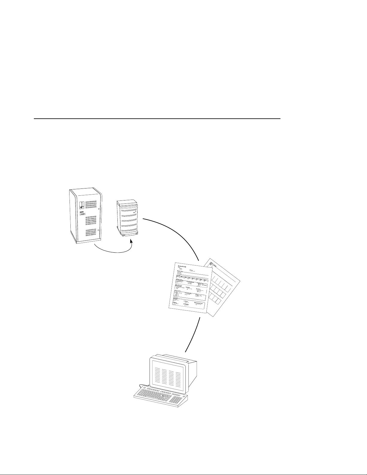
Your controller is the intelligent bridge between your host and the
devices in your subsystem.
From the host’s perspective, the controller is simply another SCSI
device connected to one of its I/O buses . Consequently, the host sends
its I/O requests to the controller just as it would to any SCSI device.
Figure 1–1 Bridgin g t he Gap Between the Host and Its Storage
Subsystem
Host
Controller
Storage
subsystem
CXO5505A
From the subsyst em’s perspective, the controller receives the I/O
requests from th e hos t and directs them to the devices in the
subsystem. Be ca use the controller processes all of the I/O requests, in
most cases it e liminates the host-base d processing that is typically
associated with reading and writing data to multiple storage devices.
The controll er does much more than simply manage I/O requests: it
provide s th e ability to combine seve ral ordinary disk drives into a
single, high-performance storage unit called a storageset.
Storagesets are implementations of RAID technology, also known as a
“Redundant Array of Indepe ndent Disks.” Every storagese t shares one
important feature: whether it uses two disk drives or ten, each
storageset looks like a single storage unit to the host.
Introduction 1–3
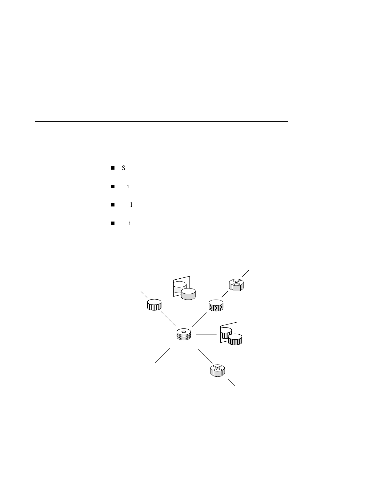
You create stora g e units by combining disk drives into storagesets,
such as stripes ets, RAIDsets, and mirrorsets, or by presenting them to
the host as single-disk units, as shown in Figure 1–2.
Stripesets (RAID 0) co mbine disk drives in serial to increase
transfer or request rates.
Mirrorsets (RAID 1) combine disk dri ves in parallel to provide a
highly reliable storage unit.
RAIDsets (RAID 3/5) combine disk drives in serial—just like
stripesets —but also store parit y data to ensure high reliability.
Striped mirrorsets (RAID 0+1) combine mirrorsets in serial to
provide the highest throughput and availability of any st orage unit.
Figure 1–2 Units Created from Storagesets, Partitions, and Disk
Drives
Unit
Partitioned
storageset
Striped
mirrorset
Unit
CXO5368A
Unit
Stripeset
Unit
Mirrorset
RAIDset
Disk drives
Partitioned
disk drive
Of course, the controller also lets you add tape drives, loaders, and
libraries to your s ubsystem to meet all of your storage requi rements.
For a complete discussion of RAID, re fer to The RAIDBOOK — A
Source Book for Disk Array Technology.

1–4 Configurat ion Manual
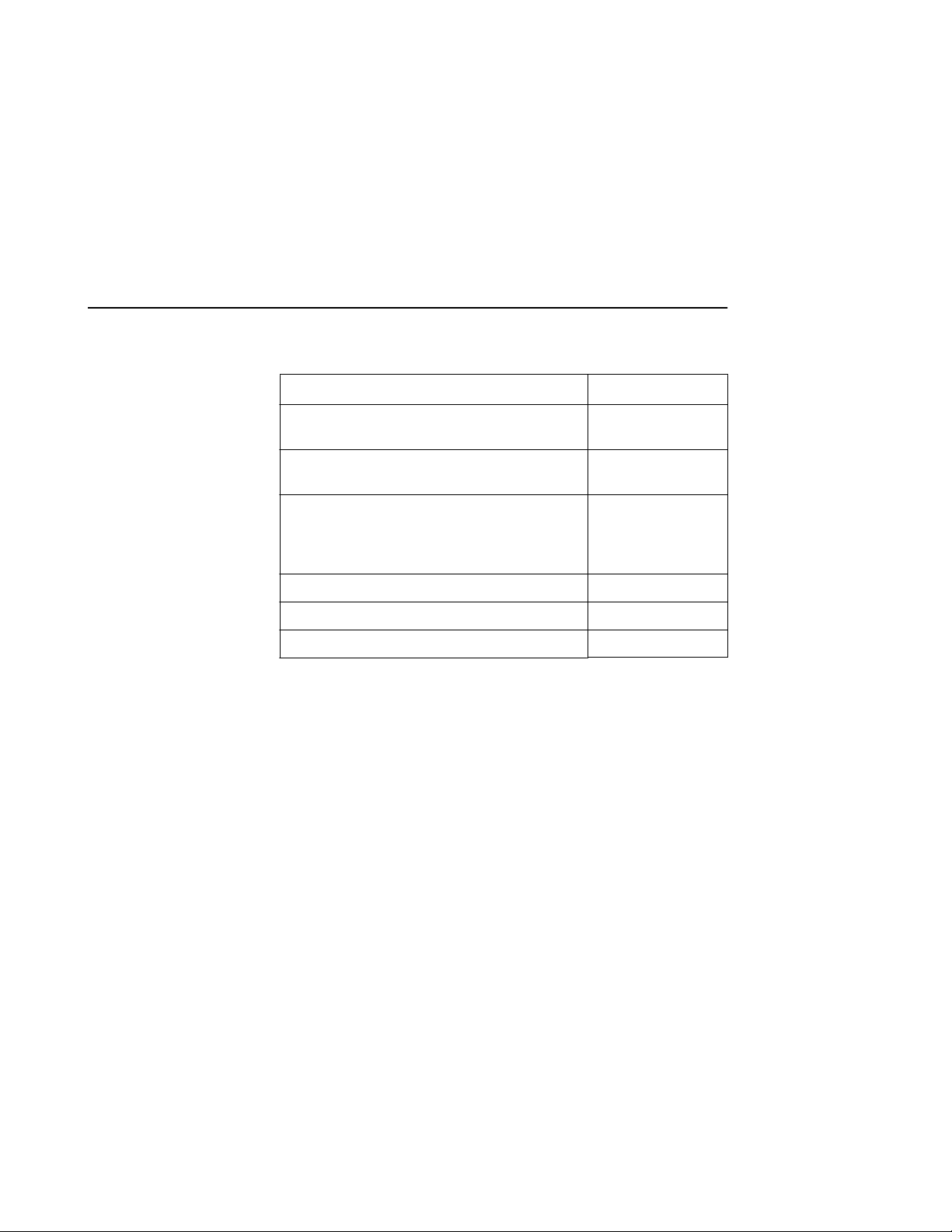
Table 1–1 summarizes the features of your controller.
Table 1–1 Summary of Controller F eatures
Feature Supported
Host protocol SCSI–2
Host bus interconnect Wide Ultr a
Differential SCS I– 2
Device protocol SCSI–2
Device bu s interconnect Fast Wide Ultra
Single-ended
SCSI-2
Number of SCSI device ports 6
Number of SCSI device tar gets per port 12
Maximum number of SCSI dev ices (with two
72
additional BA370 shelves)
RAID levels 0, 1, 0+1, 3/5
Cache size 64 or 128 MB
Mirrored write-back cache sizes 32 or 64 MB
Maximum number of host tar get ID numbers
8
per controller
Program card updates Yes
Device warm swap Yes
Exercisers for testing disks Yes
Tape drives, loaders, and libraries Yes
Number of configuration entities
191
(devices + storagesets + partitions + units)
Maximum number of RAID 5 storagesets 20
Maximum number of RAID 5 and RAID 1
storagesets
30 for dual
controller
configurations
20 for single
controller
configurations
Introduction 1–5
Table 1–1 Summary of Controller Features (Continued)
Feature Supported
Maximum number of RAID 5, RAID 1, and
45
RAID 0 stor agesets
Maximum number of partitions per s torageset
8
or disk drive
Maximum number of units prese nted to host 64 (63 if you’re
using the
StorageWorks
Command Console)
Maximum number of devices per unit 32
Maximum host port trans f er s peed 20 MHz
Largest device, storageset, or unit 120 GB
1–6 Configurat ion Manual
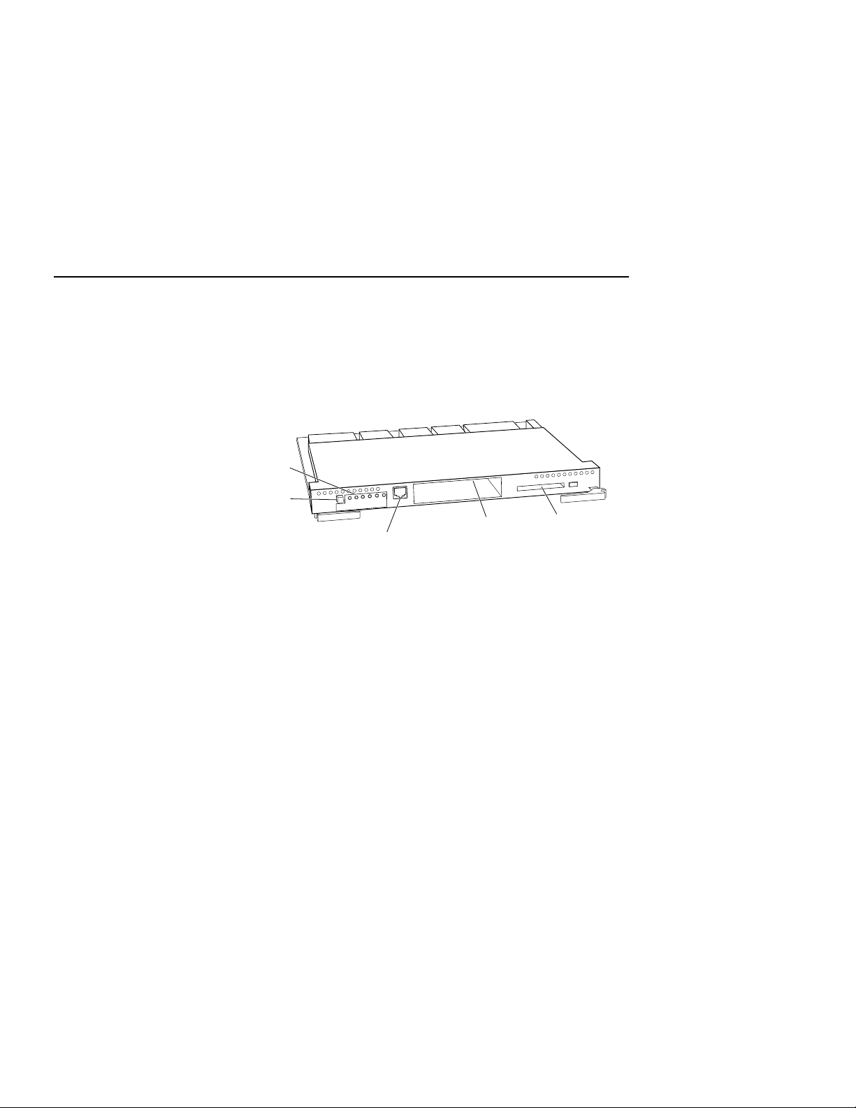
Controller Components
Take a few moments to f amiliarize yourself with the controller’s
components shown in Figure 1–3.
Figure 1–3 Key Controller Components
Control
panel
Reset
button
Under normal circumstan ces, you will not need to remove the
controller from its cabinet. For this r eason, the components that you
will use most often are conveniently located on the front panel. For
example, the local-connection port provides a convenient way to
connect a terminal to your controller so that you can interact with it.
Local-connection
port
Host
port
Program-card
slot
CXO5503B
After you configure your controller, you should periodically check its
control panel . Th e reset button flashes green about once every second
to indicate that the controller is operating normally. If an error occurs,
one or more of the amber LED lights on the control panel will flash in
a pattern that will help you to diagnose the problem. See the HSZ70
Array Controller HSOF Version 7.0 Service Manual for details about
troubleshooting your controller.
The host port and program-card slot are also located on the front panel,
making it easy to update the controller software or to connect the
controller to a different host.
The backplane enables two contr o llers to commun icate with each other
in dual-redunda nt configurations. It also contains device ports that
enable the co ntroller to communicate wit h the devices in your
subsystem.
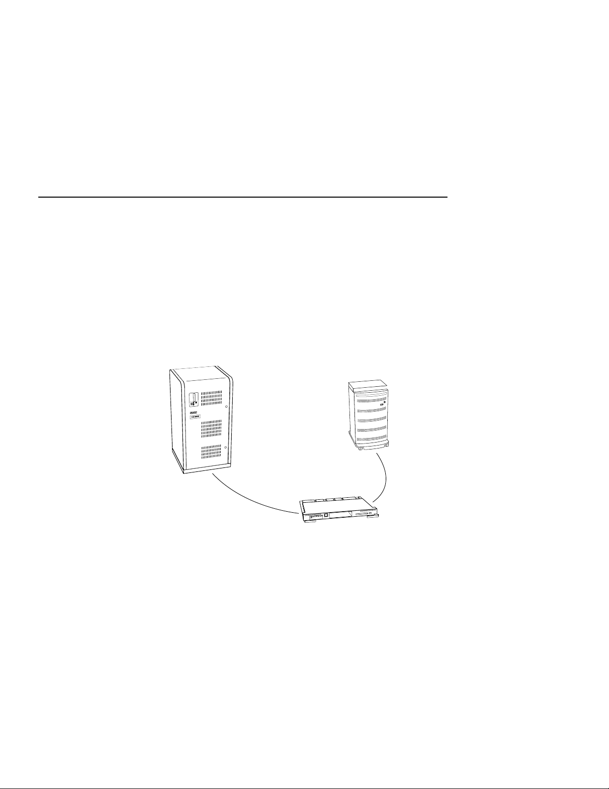
Key Steps for Configuring Your Subsystem
Figure 1–4 shows the key steps you will follow to set up and configure
your subsystem and it s controller. Each of these key steps are
explained later in this book.
Figure 1–4 Overview of Configuring a Subsystem
Configure the controller and connect it
to the host as described in Chapter 2.
Storage
Host
Plan your storages ets as
described in Chapter 3.
cabinet
Introduction 1–7
Use Command Console or
CFMENU to create storagesets.
StorageWorks Command
Console is described in Getting
Started with Command Console.
CFMENU is described in
Chapter 4.
CXO5504A


2–1
CHAPTER
2
Configuring an HSZ70 Array Controller
This chapter contains information about configuring an HSZ70 array controller and
the modules that su pport its operation in a StorageWorks subsys tem.
2–2 Configurat ion Manual
Introduction
Configuration Rules
Unless you specifically requested a preco nfigured subsystem, you will
have to configure your controller and its subsystem before you can use
them. Use the procedure in this chapter to configure your controller.
The procedure contains references to more detailed information should
you need it.
For the complete syntax and descriptions of the CLI commands used in
the configuration procedure, see the HSZ70 Array Contr oller HSOF
Version 7.0 CLI Refe re nce Manual.
Before you configure your controller, review these c onfiguration rules
and ensure your planned configuration meets t he requirements and
conditions.
Maximum 64 assignable, host-visible LUNs (maximum 63
assignable when us ing StorageWorks Command Console)
Maximum 120 GB LUN capacity
Maximum 72 physical devices
Maximum 20 RAID-5 storagesets
Maximum 30 RAID-5 and RAID-1 storagesets for dual controller
configurati ons. Maximum 20 for single controller configurations.
Maximum 45 RAID-5, RAID-1, and RAID-0 storagesets
Maximum 8 partitions per storageset or individual disk
Maximum 6 members per mirrorse t
Maximum 14 members p er RAIDse t or stripe set
Maximum 32 physical device members total for a unit
Maximum 1 external tape device per device port. If you have an
external tape drive on a port, you cannot configure any other
devices (disks or ta pes) on that port.
Maximum 1 internal (within an S BB) tape per device port. You can
configure disks in the remaining slots on the port.

Configuring a Controller
You can use this proce dure to configure your controll er in a single,
transpar ent failover, or multiple-bus failo ver configuration. Use the
refer en ces in each step to locate details about the comm and s and
concepts.
To configure a controller:
1. Use the power-verification and addressing (PVA) module ID switch to
set the SCSI ID for the BA370 rack-mountable enclosure.
See “Setting the PVA Module ID Switch,” page 2-6, for details about
PVA switch settings.
2. Es tablish a local connecti on to the controller.
See “Establishing a Local Connection to the Controller,” page 2-7, for
details about creating a local connection.
3. Ch oose a single or failov er configuration for the controller:
a. If you are configuring a single controller, skip to step 7.
Configuring an HSZ70 Array Controller 2–3
b. If you are conf igu ring d ual redu ndant c ontrolle rs in t ran spare nt
failover mode, skip to step 4.
c. If you are configuring dual-redundant controllers in multiple-
bus (some t im e s ca ll ed ho st-ass ist ed ) fa il ove r mo d e, skip to
step 5.
4. Put “this controller” into transparent failover mode. Use the following
syntax:
SET FAILOVER COPY = THIS_CONTROLLER
The “oth er co n tro ll er ” inherit s “t hi s co n tr o l le r ’s” configu ra t io n , th en
restarts. Wait for it to return to normal operation before continuing.
See details about failover modes in “Selecting a Failover Mode,” page
2-9.
Skip to s te p 6 .
5. Put “this controller” in multiple-bus failover mode, using the following
syntax:
SET MULTIBUS_FAILOVER COPY = THIS_CONTROLLER

2–4 Configurat ion Manual
6. In a transparent failover configuration, if you want to enable mirrored
7. Set the SCSI target IDs for the contro ller. Use the following syntax:
The “oth er co n tro ll er ” inherit s “t hi s co n tr o l le r ’s” configu ra t io n , th en
restarts. Wait for it to return to normal operation before continuing.
See “Selecting a Failover Mode,” page 2-9, for details about failover
modes.
Skip to s te p 7 .
write-back cache, enter this single command:
SET THIS_CONTROLLER MIRRORED_CACHE
Note Both controlle rs restart when you set mirror mode. This process
can take up to 5 minutes depending on the amount of data tha t must be
flushed from cache.
See “Selecting a Ca che Mode,” page 2-10, for details about mirr ored
write-back cache .
SET THIS_CONTROLLER ID = (n,n,n,n)
If you are configuring controllers in a dua l-redundant configura tion,
issue this one command to set the ID numbers for both controllers.
See “Setting the PVA Module ID Switch,” page 2-6, for details about
valid S C S I target ID nu mber s .
8. In dual-redundant configurations, prefer SCSI target ID numbers to the
controllers:
a. If you’re configuring controllers in transparent failover mode,
prefer some or all SCSI target ID numbers to “this contro ller.”
Use the fo ll ow in g synt ax :
SET THIS_CONTROLLER PREFERRED_ID =
(n,n)
where n,n is a subset of the ta rget ID numbers you declared in
step 7.
b. If you’re configuring controllers in a multiple-bus fa ilover
confi gura tion, pr efer spec if ic unit s to the controll ers by iss uin g
the following commands. Use the following synta x:
unit-number
SET
unit-number
SET
PREFERRED_PATH=THIS_CONTROLLER
PREFERRED_PATH=OTHER_CONTROLLER

Configuring an HSZ70 Array Controller 2–5
See “Using Prefer red ID Numb ers ,” page 2-19, for details about
preferred SCSI target ID numbers.
9. Opt ional: Change the CLI prompt. Use the following syntax:
SET THIS_CONTROLLER PROMPT = “new prompt”
If you’re configuring dual-redundant controllers , also change the CLI
prompt on the “other controller.” Use the following syntax:
SET OT HE R_CO N TRO LLE R PR OM PT = “new prompt”
See the HSZ70 Array Controller HSOF Versi on 7.0 CLI Reference
Manual for more information about using the SET
OTHER_CONTROLLER PROMPT= command.
10. Optional: Set the maximum data-transfer rate. Use the following syntax:
SET THIS_CONTROLLER TRANSFER_RATE_REQUESTED=speed
If you’re configuring dual-redundant controllers, also set the transfer
rate for the “other controlle r.” Set the same rate for both controller s.
Use the fo ll ow in g synt ax :
SET OTHER_CONTROLLER TRANSFER_RATE_REQUESTED=spee d
See “Setting the Maximum Data-Transfer Rate,” page 2-20, for an
explan ation of the transf er rate and how to set it.
11. Optional: Indicate that your subsystem power is support ed by a UPS.
Use the fo ll ow in g synt ax :
SET THIS_CONTROLLER CACHE_UPS
If you’re configuring dual-redundant controllers , also indicate that the
“other controller’s” po wer is su pported by a UPS. Use the following
syntax:
SET OTHER_CONTROLLER CACHE_UPS
See “Backing up Power with a UPS,” page 2-20, for more information.
12. Restart the controller, using the foll owing syntax:
RESTART THIS_CONTROLLER
See the RESTART THIS_CONTROLLER com ma n d in the HSZ70
Array Controller HSOF Version 7.0 CLI Reference Manual for more
information about using this command.
13. When the CLI prompt rea ppears, di spla y deta il s abo ut the contro lle r y ou
configured. Use the following syntax:
SHOW THIS_CONTROLLER FULL

2–6 Configurat ion Manual
See the SHOW THIS_CONTROLLER FULL command in the HSZ70
Array Controller HSOF Version 7.0 CLI Reference Manual for more
information about using this command.
14. Connect the controller to the host.
See “Connecting a Controller to the Host,” page 2-21, for information
about how to complete the connection.
15. Plan and configure storages ets for your subsystem.
See Chapter 3, “Planning Storagesets,” and Chapter 4, “Configuring
Storagesets” for detailed information about planning and configuring
storagesets.
Setting the PVA Module ID Switch
The PVA module provides unique addr es ses to extended subsystems.
Each BA37 0 rack -mountable enclosure in an ext ended subsystem must
have its own PVA ID. Use PVA ID 0 for the enclosure that c o n tains the
controllers . Use PVA IDs 2 and 3 for the additional enclosures. Figure
2–1 illustrates the PVA settings in an extended subsystem.
See the documentation that accompanied your enclosure for more
details about the PVA and its settings.
 Loading...