

Digital Equipment StorageWorks DS-BA35X-MN Installation Manual
DIGITAL StorageWorks
Single-Ended I/O Module
Installation Guide
This guide describes the procedures for removing and
installing an ultra SCSI RAID single-ended I/O module (I/O
module) assembly, model DS–BA35X–MN.
CXO5816A
____________ CAUTION ________________
To protect this sensitive electronic device from
electrostatic discharge (ESD) use the following
precautions—(1) Wear an ESD wrist strap.
(2) Do not touch the printed circuit board or the
backplane connector. (3) Do not lay the device
on a work surface but place it on an electrostatic
mat. (4) Place the device in an electrostatic bag
for shipment.
__________________________________________
_____________ Caution _________________
3. Shut down the redundant controller by entering the
command—shutdown other_controller
4. Shut down the primary controller by entering the
command—shutdown this_controller
5. After shutting down both controllers, turn off the ac
power controllers in all the enclosures.
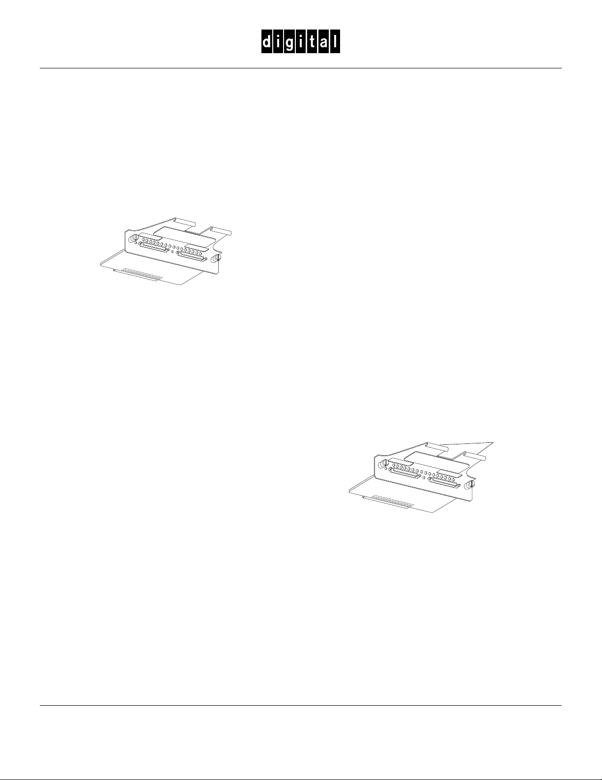
Removing an I/O Module
______________ Note ___________________
Complete this section only when you are replacing
an I/O module.
__________________________________________
After turning off the subsystem,, complete the following
procedure to remove an I/O module from the ultra SCSI
RAID enclosure.
1. Use a flat-tip screwdriver to loosen the two, spring-loaded
mounting screws on the module.
Cable support
brackets
Removing an I/O module disconnects the SCSI
bus TERMPOWER and will result in corrupted
and lost data. Therefore, you must turn off the
subsystem before removing the I/O module.
__________________________________________
Grasp the module by the cable support bracket and pull it
directly to the rear to remove it from the enclosure
shroud.
CXO5853A
.
Turning Off the
Cut and remove the wire ties.
Subsystem
Complete the following procedure before removing or
installing an I/O module:
1. On the host, dismount the ultra SCSI RAID subsystem
storage devices.
2. Connect a maintenance terminal to the primary
controller.
™ StorageWorks and the DIGITAL logo are trademarks of Digital Equipment Corporation. EK–35XMN–IG .A01
©Digital Equipment Corporation 1997 May 1997
Printed in the U.S.A.
All Rights Reserved.
2. Loosen the thumb screws on the left module cable
connector.
Remove the cable and label it as Cable A.
3. Loosen the thumb screws on the right module cable
connector.
Remove the cable and label it as Cable B.
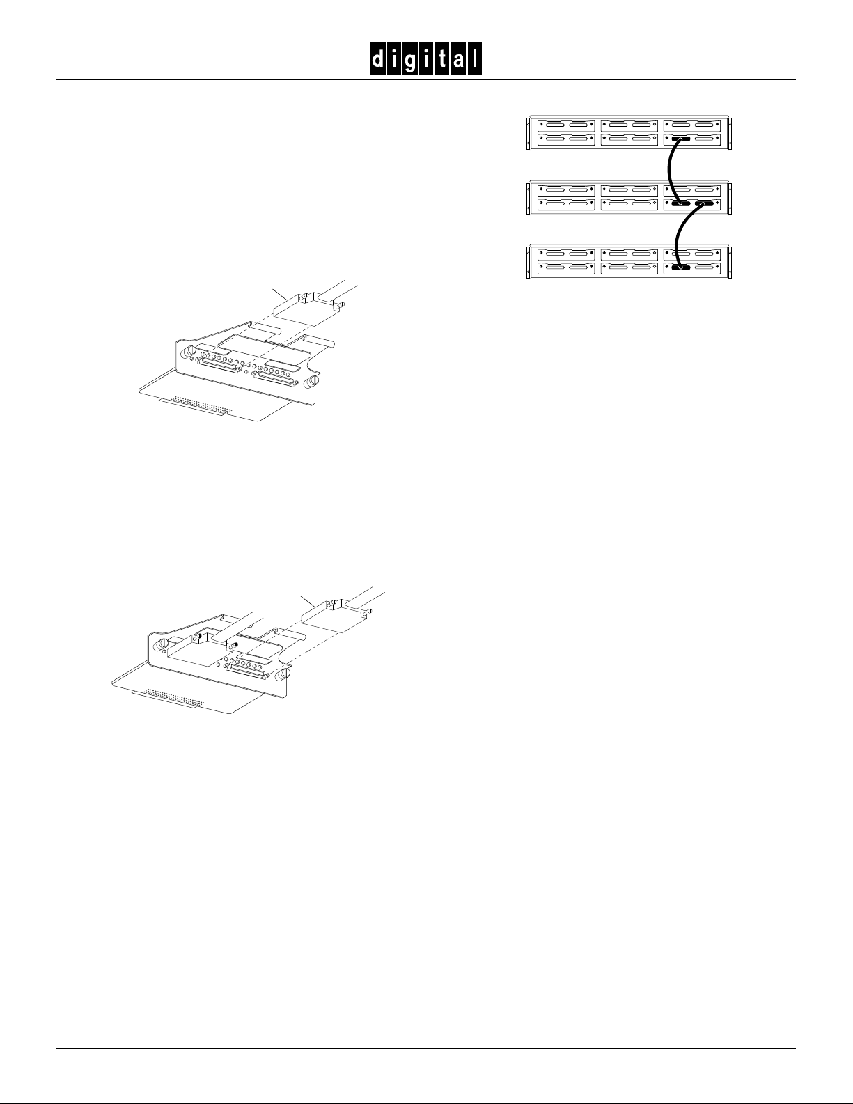
Installing an I/O Module
642
Complete the following procedures to install an I/O module in
an ultra SCSI RAID enclosure.
1. Remove the I/O module from the electrostatic bag.
Verify that the unit is the correct model by checking the
label.
2. Align Cable A with the left cable connector.
Cable A
CXO5854A
Gently insert the cable connector into module connector.
Tighten both cable connector thumb screws to fully seat
the connector.
3. Insert a wire tie through the hole in cable support bracket.
Route the wire tie around the support bracket and the
cable. Tighten the wire tie.
4. Align Cable B with the right cable connector.
Cable B
531
642
531
642
531
Cable A
Cable B
CXO5841A
7. Repeat this procedure to install each I/O module.
Turning On the Subsystem
After connecting the cables and installing the I/O modules,
complete the following procedure:
1. Restore power to each of the enclosures by turning O
the ac power controllers.
2. On the primary controller, press and hold the Reset
switch for at least 3 seconds.
3. From the maintenance terminal, enter the command—
show other_controller
Verify that the controller is functioning correctly
4. On the redundant controller, press and hold the Reset
switch for at least 3 seconds.
N
all
CXO5855A
Gently insert the cable connector into module connector.
Tighten both cable connector thumb screws to fully seat
the connector.
5. Insert a wire tie through the hole in cable support bracket.
Route the wire tie around the support bracket and the
cable. Tighten the wire tie.
6. Align the module with the enclosure card guides. Gently
insert the module and firmly seat it. Use a screwdriver to
tighten the spring-loaded mounting screws.
_______________CAUTION ______________
To prevent damaging the mounting screws do not
over tighten the screw.
______________________________________
5. From the maintenance terminal, enter the command—
show other_controller
Verify that the controller is functioning correctly
6. Check the subsystem for proper operation.
______________ Note ___________________
For detailed information about the operation,
function, status, error conditions, fault conditions,
and displays of this device, refer to the DIGITAL
StorageWorks Ultra SCSI RAID Enclosure User’s
Guide.
__________________________________________
2
 Loading...