

Digital Equipment STARION 200i, STARION 300i Service Maintenance Manual

Service
Maintenance
Manual
STARION 200i/300i
PC Family
EK-A0851-SV. A01
S
T
A
R
I
O
N
2
0
0
i
Copyright Digital Equipment Corporation
All rights reserved
3
0
0

January 1996
January 1996
The information in this document is subject to change without notice and should not be construed as a
commitment by Digital Equipment Corporation.
Digital Equipment Corporation assumes no responsibility for any errors that might appear in this
document.
The software, if any, described in this document is furnished under a license and may be used or copied
only in accordance with the terms of such license. No responsibility is assumed for the use or reliability of
software or equipment that is not supplied by Digital Equipment Corporation or its affiliated companies.
Restricted Rights: Use, duplication, or disclosure by the U.S. Government is subject to restrictions as set
forth in subparagraph (c) (1) (ii) of the Rights in Technical Data and Computer Software clause at DFARS
252.227-7013.
Copyright Digital Equipment Corporation
All Rights Reserved
The following are trademarks of Digital Equipment Corporation:
STARION and the Digital logo.
The following are third party trademarks:
MS-DOS and Windows and Windows NT and Windows NT Server are trademarks of Microsoft Corp.
Novell and Netware are trademarks of Novell, Inc.
SCO and Open Desktop are trademarks of The Santa Cruz Operation, Inc.
UNIX is a registered trademark of UNIX System Laboratories, Inc.
All other trademarks and registered trademarks are the property of their respective holders.
Created by:
MCS Logistics Engineering - Nijmegen
Printed in Ireland

Digital STARION 200i/300i PC Table of Contents
Table of Contents
REVISION HISTORY................................................................................................................................7
PREFACE....................................................................................................................................................9
CHAPTER 1 PRODUCT DESCRIPTION............................................................................................11
P
RODUCT INTRODUCTION
P
RODUCT MODELS INFORMATION
CHAPTER 2 SYSTEM UTILITIES& CONFIGURATION................................................................15
S
YSTEM UTILITIES
Before Using System Utilities and Video Drivers...................................................................................15
Using Utilities & Video Drivers .............................................................................................................15
PHLASH .EXE.......................................................................................................................................16
Before Using PHLASH.EXE........................................................................................................ ..........16
Creating a Crisis Recovery Diskette.......................................................................................................16
Using a Crisis Recovery Diskette ...........................................................................................................18
Upgrading the Computer's BIOS............................................................................................................18
U
LTILITIES AND VIDEO DRIVERS
Setting High Resolution Mode for the Monitor Display.........................................................................20
Windows Video Drivers .........................................................................................................................21
MS-DOS Application Video Drivers......................................................................................................21
Using the S3refrsh Utility.......................................................................................................................22
CO/Session and Remote Support............................................................................................................22
BIOS S
ETUP UTILITY
Running the BIOS setup Ultility.............................................................................................................23
Updating The Computer's Configuration................................................................................................23
Helpful Hints.......................................................................................................................................... 23
BIOS Setup Utility Options....................................................................................................................24
Main Menu Options................................................................................................................................24
Hard Disk Options..................................................................................................................................24
Memory and Cache................................................................................................................................. 26
Boot Options...........................................................................................................................................28
Keyboard Features..................................................................................................................................30
Advanced Options ..................................................................................................................................30
Integrated Peripherals .............................................................................................................................30
Advanced Chipset Control......................................................................................................................31
Security Options.....................................................................................................................................33
Power Options ........................................................................................................................................34
CHAPTER 3 SERVICE PROCEDURES..............................................................................................37
S
AFETY REQUIREMENTS
R
ECOMMENDED TOOLS
Other Needed Materials..........................................................................................................................38
Remedial Diagnostic Test Software........................................................................................................38
.............................................................................................................................11
................................................................................................................13
........................................................................................................................................ 15
..................................................................................................................20
................................................................................................................................... 22
...............................................................................................................................37
................................................................................................................................38
S
T
A
R
I
O
N
2
0
0
i
3
0
0
MCS Logistics Engineering - Nijmegen 3

Table of Contents Digital STARION 200i/300i PC
Recommended Virus Detection and Cleanup Software ..........................................................................38
S
T
A
R
I
O
N
4 MCS Logistics Engineering - Nijmegen
2
0
0
i
3
0
0

Digital STARION 200i/300i PC Table of Contents
ECO/FCO I
NFORMATION
.............................................................................................................................39
BIOS version information.......................................................................................................................39
U
NLOCKING AND REMOVING THE COVER
C
OMPUTER COMPONENTS
E
XPANSION SLOTS
M
AIN LOGIC BOARD JUMPERS
............................................................................................................................41
........................................................................................................................................ 42
.....................................................................................................................44
....................................................................................................39
Main Logic Board Jumper Settings ........................................................................................................44
Main Logic Board Jumper Locations......................................................................................................45
C
OMPUTER MEMORY CONFIGURATIONS
......................................................................................................46
Memory Configurations..........................................................................................................................46
SIMM Sockets Locations........................................................................................................................46
P
ART REMOVAL AND REPLACEMENT
...........................................................................................................48
Opening the Device Bay & Power Supply Subassembly ........................................................................48
Removing the 3½-Inch Diskette Drive. ..................................................................................................50
Removing the Main Logic Board ...........................................................................................................51
Removing the Power Supply...................................................................................................................52
Removing the Riser Card & Bracket ......................................................................................................53
Removing Expansion Boards..................................................................................................................54
Removing a 3½-Inch Mass Storage Device (Internal Drive Bay)...........................................................55
I
NSTALLATION PROCEDURES
........................................................................................................................56
Installing a Higher Performance CPU..................................................................................................... 56
Installing the CPU Voltage Regulator..................................................................................................... 58
R
EPLACEMENT PROCEDURES
.......................................................................................................................59
Replacing the Real-Time Clock (RTC)...................................................................................................59
C
ONNECTING DISKETTE AND
IDE D
.................................................................................................61
EVICES
Connecting Diskette Drives....................................................................................................................62
Connecting IDE Devices.........................................................................................................................63
CHAPTER 4 TROUBLESHOOTING...................................................................................................65
I
NITIAL TROUBLESHOOTING
B
EEP CODES
POST
.................................................................................................................................................66
AND BOOT MESSAGES
.........................................................................................................................65
.......................................................................................................................67
POST and Boot Error Messages .............................................................................................................67
POST and Boot Informational Messages................................................................................................70
C
OMPUTER TROUBLESHOOTING
D
ISK DRIVE TROUBLESHOOTING
M
ONITOR TROUBLESHOOTING
CD-ROM T
QAP
ROUBLESHOOTING
/FE E
LUS
RROR MESSAGES
...................................................................................................................70
..................................................................................................................75
.....................................................................................................................75
.....................................................................................................................76
...................................................................................................................77
CHAPTER 5 DEVICE MAPPING ........................................................................................................79
CPU Memory Address Map (Full Range)............................................................................................... 79
I/O Address Map.....................................................................................................................................80
Computer Interrupt Levels...................................................................................................... ................81
DMA Channel Assignment.....................................................................................................................81
CHAPTER 6 PASS / FAIL CRITERIA.................................................................................................83
S
T
A
R
I
O
N
2
0
0
i
3
0
0
MCS Logistics Engineering - Nijmegen 5

Table of Contents Digital STARION 200i/300i PC
APPENDIX A SERVICES NOTES........................................................................................................85
Modem Settings......................................................................................................................................85
Telecommunications Software Settings ..................................................................................................85
Sound Card Settings................................................................................................................................86
Disabling Fax/Modem/Sound Board Features ........................................................................................86
APPENDIX B USEFUL INFORMATION ............................................................................................87
R
ELATED DOCUMENTATION
O
N-LINE BULLETIN BOARDS
DOCUMENT FEEDBACK.......................................................................................................................89
PERSONAL NOTES.................................................................................................................................91
READERS COMMENTS............................................................................................................................95
..........................................................................................................................87
........................................................................................................................87
Table of Figures
Figure 3 - 1 Unlocking the Cover................................................................................................................40
Figure 3 - 2 Release Cover..........................................................................................................................40
Figure 3 - 3 Removing the Cover................................................................................................................40
Figure 3 - 4 Computer Components............................................................................................................41
Figure 3 - 5 Expansion Slots.......................................................................................................................43
Figure 3 - 6 Main Logic Board Jumper Locations ......................................................................................45
Figure 3 - 7 SIMM Socket Locations..........................................................................................................47
Figure 3 - 8 Release Front Locking Mechanisme........................................................................................48
Figure 3 - 9 Opening the Device Bay & Power Supply Subassembly.........................................................49
Figure 3 - 10 Removing the 3½-Inch Diskette Drive..................................................................................50
Figure 3 - 11 Removing the Main Logic Board..........................................................................................51
Figure 3 - 11 Removing the on Power Supply ............................................................................................52
Figure 3 - 12 Removing the Riser Card & Bracket.....................................................................................53
Figure 3 - 13 Removing Expansion Boards ................................................................................................54
Figure 3 - 14 Open Power Supply Subassembly .........................................................................................55
Figure 3 - 15 Removing the 3.5-Inch Device..............................................................................................55
Figure 3 - 16 Installing a Higher Performance CPU ...................................................................................57
Figure 3 - 17 Installing the CPU Voltage Regulator ...................................................................................58
Figure 3 - 18 Replacing the Real Time Clock.............................................................................................60
Figure 3 - 19 Diskette Drive Data Cable Connections................................................................................62
Figure 3 - 20 IDE Drive Data Cable Connections.......................................................................................63
S
T
A
R
I
O
N
2
0
0
i
3
0
0
6 MCS Logistics Engineering - Nijmegen
Digital STARION 200i/300i PC Revision History
Revision History
Revision of Date Description of change
EK-A0851-SV First release of the Service Manintenance Manual describing t he
STARION 200i/300i series computer.
S
T
A
R
I
O
N
MCS Logistics Engineering - Nijmegen 7
2
0
0
i
3
0
0

Digital STARION 200i/300i PC Preface
f
Preface
The Digital STARION 200i/300i PC Family Service Maintenance Manual is a troubleshooting guide that
can be used for reference when servicing the STARION 200i/300i line of PC’s.
Digital Equipment Corporation reserves the right to make changes to the Digital STARION 200i/300i
series without notice. Accordingly, the diagrams and procedures in this document may not apply to the
computer(s) you are servicing since many of the diagnostic tests are designed to test more than one
product.
CAUTION
Digital recommends that only A+ certified engineers attempt to repair this equipment.
All troubleshooti ng and r epa ir pr oc edur es a re deta il ed to suppo rt subasse mbly/module
level exchange. Because of the complexity of the indivual boards and subassemblies, no
one should attempt to make repairs at component level or to make modifications to any
printed wiring board. Improper repairs can create a safety hazard. Any indications o
component replacement or printed wiring board modifications may void warranty or
exchange allowances.
S
T
A
R
I
O
N
MCS Logistics Engineering - Nijmegen 9
2
0
0
i
3
0
0


Digital STARION 200i/300i PC Product Description
Chapter 1 Product Description
Product Introduction
The Digital STARION 200i/300i computers are high-performance, multi-media, personal computers
featuring the latest in computing technology. They can be used as stand-alone computers, as clients, or as
servers in a network environment. Developed using the following state-of-the-art technology, these
computers are the most value packed full-profile desktop computers in their class.
♦ Microprocessor
◊ 75 Mhz Pentium
♦ System Memory
◊ 8MB System RAM, expandable to 128MB
♦ Onboard Video
◊ S3 Trio 32 technology to take full advantage of the computer’s CPU
♦ CD-ROM Reader
◊ Double-speed CD-ROM reader with industry-standard IDE/ATAPI interface and audio
capability.
♦ Fax/Modem/Sound Card
Sophisticated fax/data/voice modem and 16-bit FM synthesis sound card. Some features of this card
are:
◊ 14,400 bps internal fax/modem
◊ Error correction and data compression (V.42bis/MNP-5)
◊ Fax capability directly from Microsoft Windows 3.1 applications
◊ Digital telephone answering Device
◊ 16-bit stereo recording at 11 kHz, 22 kHzand 44 kHz sampling
◊ 16-bit stereo playback at 8 kHz to 44 kHz sampling rates
◊ Supports Windows Sound System
S
T
A
R
I
O
N
2
0
0
i
3
0
0
MCS Logistics Engineering - Nijmegen 11

Product Description Digital STARION 200i/300i PC
◊ Support Sound Blaster and Sound Blaster Pro sound standards
12 MCS Logistics Engineering - Nijmegen

Digital STARION 200i/300i PC Product Description
Product Models Information
STARION 200i/300i Models
Product Model Memory HDD Cache CD-ROM
STARION 200i FR-901AA-A4
STARION 300i FR-901AA-A5
8MB 540MB None Dual-Speed
8MB 840MB None Dual-Speed
S
T
A
R
I
O
N
MCS Logistics Engineering - Nijmegen 13
2
0
0
i
3
0
0


Digital STARION 200i/300i PC Utilities & Configuration
Chapter 2 System Utilities& Configuration
System Utilities
This chapter describes how to use the utilities and video drivers supplied with the STARION 200i/300i
computer. These utilities and drivers have been factory installed on the hard disk drive. You may use the
video utilities to change video graphics settings of the monitor. Additional video drivers, utility
programsand device drivers have also been factory installed as image files on the hard disk drive. This
chapter also describes PHLASH.EXE, which is not supplied with the computer. This utility is available
only via bulletin board distribution to customers needing BIOS upgrades.
Before Using System Utilities and Video Drivers
When unfamiliar with utility programs, video drivers and their uses, carefully read and understand this
chapter before attempting to use any of the utilities or to install video drivers.
Using Utilities & Video Drivers
The system utilities and video drivers enable to take full advantage of the computers enhanced video
features. Use the following information to reset the video mode of the monitor, or to load MS-DOS
application drivers when using various non-Windows CAD or business software.
NOTE
1) Turn on or reboot th e compu t er. If POST detects an error, refer to chapter 4, “Troubleshooting” for
2) If necessary, run PHLASH.EXE to upgrade or restore the computer's BIOS.
MCS Logistics Engineering - Nijmegen 15
If this is the first time using these utility programs and/or video drivers, it is
recommended to follow the procedures in the order given.
possible causes and suggested solutions.
S
T
A
R
I
O
N
2
0
0
i
3
0
0

Utilities & Configuration Digital STARION 200i/300i PC
3) Install any applicable DOS or CAD application video drivers. Additional information about these
drivers is provided later in this chapter.
4) Install any Windows 3.x video drivers. Additional information about these drivers is provided later
in this chapter.
PHLASH .EXE
All computers have BIOS software in a read-only, non-volatile memory (ROM) chip. This BIOS initializes
hardware and boots the operating system when the computer is turned on. The BIOS also provides access
to other services such as keyboard and disk drives.
STARION Desktop PC computers are equipped with flash memory. This means that the computer's BIOS
simply can be restored by running the PHLASH.EXE utility. The computer's BIOS can be upgraded to
future releases by running PHLASH.EXE along with any flash BIOS update diskette if necessary.
Before Using PHLASH.EXE
A crisis recovery diskette should be created before PHLASH.EXE is used to upgrade the computer's BIOS.
This diskette can then be used to reprogram the computer's BIOS in case the flash process built into the
computer fails.
The following are needed to create this diskette:
♦ A blank 3½-inch 1.44 MB formatted diskette
♦ A diskette copy of the BIOS upgrade diskette
NOTE
PHLASH utilities are not shipped with STARION 200i/300i computers. However,
they are available on the Digital Bulletin Board System.
Creating a Crisis Recovery Diskette
1) Turn on the computer and allow the POST to complete.
If POST detects an error, refer to Chapter 4, “Troubleshooting” to identify and determine how to
correct the problem. After the problem has been resolved, restart the computer.
2) Insert the BIOS diskette into the diskette drive and enter: A:DIR
The entry should show that the following files are on the diskette:
Note that there are some additional files as well. Refer to the README file on the diskette for
3) Create an upgrade directory on the hard disk drive. For example, if the hard disk drive is c:>, enter at
4) Copy the files from the BIOS diskette into the upgrade directory on the hard disk drive. For example,
16 MCS Logistics Engineering - Nijmegen
MINIDOS.SYS
PHLASH.EXE
MAKEBOOT.EXE
MAKECRD.EXE
additional information.
the DOS prompt: C: MD UPGRADE.
from the DOS prompt enter: COPY A: \UPGRADE\*.* C:\UPGRADE\*.*.

Digital STARION 200i/300i PC Utilities & Configuration
5) Insert a blank formatted diskette into drive A.
S
T
A
R
I
O
N
MCS Logistics Engineering - Nijmegen 17
2
0
0
i
3
0
0

Utilities & Configuration Digital STARION 200i/300i PC
6) On drive A, make a directory for the files previously copied. For example, from the DOS prompt
enter:
A:MD UPGRADE.
7) Return to the hard disk drive and copy the files. From the DOS prompt, enter: C:MAKECRD.
The MAKECRD command prompts for a recovery diskette to be placed in drive A and then
automatically copies the files to drive A.
8) Remove the crisis recovery diskette from drive A and store it in a safe place.
Using a Crisis Recovery Diskette
The crisis recovery diskette must be used only if the computer's BIOS fails or if a BIOS upgrade was
unsuccessful.
If the computer's BIOS failed to flash properly or is corrupted in some way, the following sequence of
events occurs:
♦ POST detects an error after a normal boot cycle or a BIOS upgrade. This message(s) appears on the
monitor screen, indicating that the computer's BIOS did not flash properly or has failed.
♦ The BIOS in the bootblock memory automatically executes. The computer attempts to find the
correct BIOS files to execute the correct boot cycle.
♦ The comput er beeps several tim es. This means t he computer ca nnot properly boot using the BIOS
files that were just copied during the flash update.
♦ The computer accesses the diskette drive. The computer is searching for the crisis recovery diskette to
restore the BIOS to its previous known state.
Restore the computer's BIOS to its previous known state by performing the following procedures:
1) Turn off the computer, remove th e coverand set th e recovery mode jumper (J10) to Recovery Mode
(jumpered).
2) Replace the cover, insert the crisis recovery diskette into drive Aand then power on the computer.
3) The computer automatically boots from drive A and upgrades the BIOS. Upon completion, the
computer sounds a beep code and attempts to restart.
4) After the BIOS is restarted, turn off power to the computer and remove the crisis recovery diskette
from drive A.
5) Remove the cover and set the recovery jumper (J10) to normal.
6) Replace the cover and turn the power back on for normal operation.
Upgrading the Computer's BIOS
Perform the following steps to update the computer's BIOS in the flash memory to a new updated one:
1) Locate or create a crisis recovery diskette (Do not use a crisis recovery diskette created on any other
computer). Refer to “Creating a Crisis Recovery Diskette”.
2) Insert the BIOS diskette in the diskette drive.
3) Turn on the computer and allow the POST to complete. The computer now boots from the BIOS
diskette.
18 MCS Logistics Engineering - Nijmegen

Digital STARION 200i/300i PC Utilities & Configuration
If POST detects an error, refer to Chapter 4, “Troubleshooting” to identify and determine how to
correct the problem. After the problem has been resolved, restart the computer.
S
T
A
R
I
O
N
MCS Logistics Engineering - Nijmegen 19
2
0
0
i
3
0
0
Utilities & Configuration Digital STARION 200i/300i PC
4) At the MS-DOS prompt, type: A:\UPGRADE\PHLASH.
A screen appears on the monitor warning that the computer's BIOS is about to be erased.
5) Press [Enter] to continue. Press [Esc] to cancel.
If [Enter] is pressed, PHLASH.EXE automatically updates the computer's BIOS.
After the flashing process completes, the computer automatically reboots itself so changes
immediately take effect.
6) Remove the BIOS diskette.
Ultilities and Video Drivers
Setting High Resolution Mode for the Monitor Display
When purchasing a high resolution monitor, you might want to run the Galileo video setup utility supplied
with the computer. Galileo is a Windows-based utility used to change video resolutions, color depthsand
refresh rates to match the capabilities of the monitor.
To use Galileo to change video resolution, perform the following steps:
1) From the Windows Program Manager, double click on the Control Panel icon.
2) Next, double click on the Galileo icon to display the video console.
3) Select the monitor resolution, color depthand refresh rate to match to the monitor's specifications.
4) Select "Switches" that apply to the CAD software package. Digital recommends to leave these set to
the "Enabled" or "On" position when not sure about their functions.
5) Click "OK" to save the settings and exit the utility.
NOTE
20 MCS Logistics Engineering - Nijmegen
Video selections shaded gray are not val id choic es due to the c omputer's max imum
video memory or installed controller type.
CAUTION
Do not select a monitor type setting that exceeds the monitor's resolution, refresh rate
(vertical synchronization)and interlace or non-interlace specifications. Refer to the
monitor's support documentation for performance specifications.

Digital STARION 200i/300i PC Utilities & Configuration
Windows Video Drivers
The computer comes with the required Windows video display driver pre-installed at the factory.
However, if the hard disk drive becomes corrupted, you might need to re-load the Windows video driver
that has been provided on the Windows video driver diskette that is made using "Program Disks" and the
"Driver Disks" tab from Digital Getting Started..
Before installing a video device driver, read the information in the README.TXT file provided on the
diskette.
To re-load the Windows driver, perform the following steps:
1) Type CD WINDOWS at the C:\> prompt, then press [Enter].
The following prompt appears: C:\WINDOWS>.
2) Type SETUP and press [Enter].
The computer displays the SETUP screen.
3) Select the
4) Toggle through the Display option to select the appropriate Windows 3.x driver.
5) Select the desired video resolution then press [Enter].
6) If the approp riate vi deo dri ver resides on a separat e di skett e, toggle through th e Display option to
select Other (Requires disk provided by hardware manufacturer).
7) Insert the diskette that contains the appropriate video driver and press [Enter].
Select the desired video resolution then press [Enter].
The MS-DOS prompt appears when SETUP completes.
8) Type WIN and press [Enter] to start Microsoft Windows.
Display
option and press [Enter].
MS-DOS Application Video Drivers
Various software drivers for popular MS-DOS based CAD and business applications have been provided
on the "S3 TRIO 32 Video Drivers and Utilities" diskette that is made using the "Driver Disks" section of
"Getting Started". When using an older non-Windows application such as ACAD or Lotus for DOS,
loading one or more of these drivers may be necesarry.
Before installing a video device driver, read and understand the information in any README.TXT file
provided on the diskette.
MCS Logistics Engineering - Nijmegen 21
S
T
A
R
I
O
N
2
0
0
i
3
0
0

Utilities & Configuration Digital STARION 200i/300i PC
Using the S3refrsh Utility
S3refrsh.EXE is an MS-DOS-based utility that works in conjunction with Galileo to set the video
controller monitor resolution and refresh rates. This utility has been pre-installed and configured at the
factory to meet most monitor resolution needs. In most cases using this utility is never neededand Galileo
should only be used to select high resolution video modes. However, when Galileo cannot successfully be
used to set the required monitor mode, run S3refrsh.EXE as follows:
1) At the C:\> prompt type: S3refrsh.EXE and then press [Enter].
The S3refrsh utility screen appears.
The refresh options are shown on the left side and the corresponding resolutions are displayed on the
top of the matrix.
2) Click on the desired boxes.
The "X" mark means that a selection is not valid. Selected refresh rates are defined by check marks.
3) Click on EXIT to set the new refresh rate.
The utility will then prompt when wishing to save the changes in the AUTOEXEC.BAT file.
CO/Session and Remote Support
The "System Utility and Remote Support" diskette supplied with STARION Desktop PC computers
includes Triton's CO/Session Remote Communications Software. This software allows to remotely
troubleshoot an improperly functioning computer via a telephone/modem connection. Proper use of this
software might enable some computer problems to be corrected without requiring a further service call.
When the software is enabled, tasks can perform via telephone on the user's computer include:
♦ Editing system files such as AUTOEXEC.BAT, CONFIG.SYS and WIN.INI.
♦ Transmitting files, such as updated device drivers, to the remote PC.
♦ Relaying instructions to the user via a "chat mode" display.
♦ Printing information to the user's printer.
Consult appropriate documentation and training materials for information on using the Co/Session
software.
BIOS Setup Utility
This chapter provides information on how to configure the computer using the BIOS Setup utility. If the
computer was delivered with factory-installed software, it has already been configured.
When familiar with utility programs and their uses, refer to the appropriate sections in this chapter to set
up or update the computer. Otherwise, carefully read this chapter before attempting to modify the
computer's configuration settings.
22 MCS Logistics Engineering - Nijmegen

Digital STARION 200i/300i PC Utilities & Configuration
Running the BIOS setup Ultility
The BIOS Setup utility enables to select and permanently store information about the computer's hardware
and software in the battery-backed memory of the CMOS RAM. This information takes effect each time
the computer boots and can be changed each time setup is runned.
Use the BIOS Setup utility when experiencing problems with the hard disk or when reconfiguration of the
computer is necessary. In addition, it might be necessary to use the BIOS Setup utility to modify the
configuration after you add or remove hardware, or change computer settings.
To run the BIOS Setup utility, perform the following steps:
1) Turn on the computer and allow the POST to complete.
2) Make a note of any configuration errors listed and then press [F2] to display the main menu.
3) Follow the instructions on the monitor screen and any on-line help pop-up screens to configure the
computer.
Updating The Computer's Configuration
The following sections list the BIOS Setup utility options that can be updated or modified using the
following menu selections:
♦ Main enables to set basic computer configuration options (time, date, video, etc.).
♦ Advanced enables to set advanced features to increase computer performance (memory, COM
ports, LPT port, etc.).
♦ Security enables to set passwords and backup data reminders.
♦ Power enables to set power saving options to conserve electricity and increase the life of the
computer.
♦ Exit enables to quit the current menu and save setup changes.
Helpful Hints
Below are some helpful hints when using the BIOS Setup utility:
1) Several keyboard function keys and numeric keypad keys are assigned to help select menus and submenus, options, changing option valuesand displaying help information. These keys are displayed at
the bottom of the main menu and from the General Help pop-up screen.
2) Item-specific help is available anytime during the setup process and appears at the right of the setup
screen each time an option is highlighted. This on-line help provides information about a highlighted
option.
3) Select “Save Changes & Exit” to save all Setup values.
4) Select “Discard Changes & Exit” to exit Setup without recording any changes.
5) Select “Get Default Values” to set all Setup options to their default values.
6) Select “Load Previous Changes” to restore all CMOS values from the last session.
7) Select “Save Changes” to save all selections without exiting Setup.
8) Press [Esc] to exit the Setup utility.
S
T
A
R
I
O
N
2
0
0
i
3
0
0
MCS Logistics Engineering - Nijmegen 23
Utilities & Configuration Digital STARION 200i/300i PC
r
BIOS Setup Utility Options
The following topics list the BIOS options that can be updated or modified by using the BIOS Setup utility,
according to the various sub-menus under which they appear.
NOTE
In some cases, opti ons might be list ed in a dif ferent order than they actual ly appea
in the sub-menus.
Main Menu Options
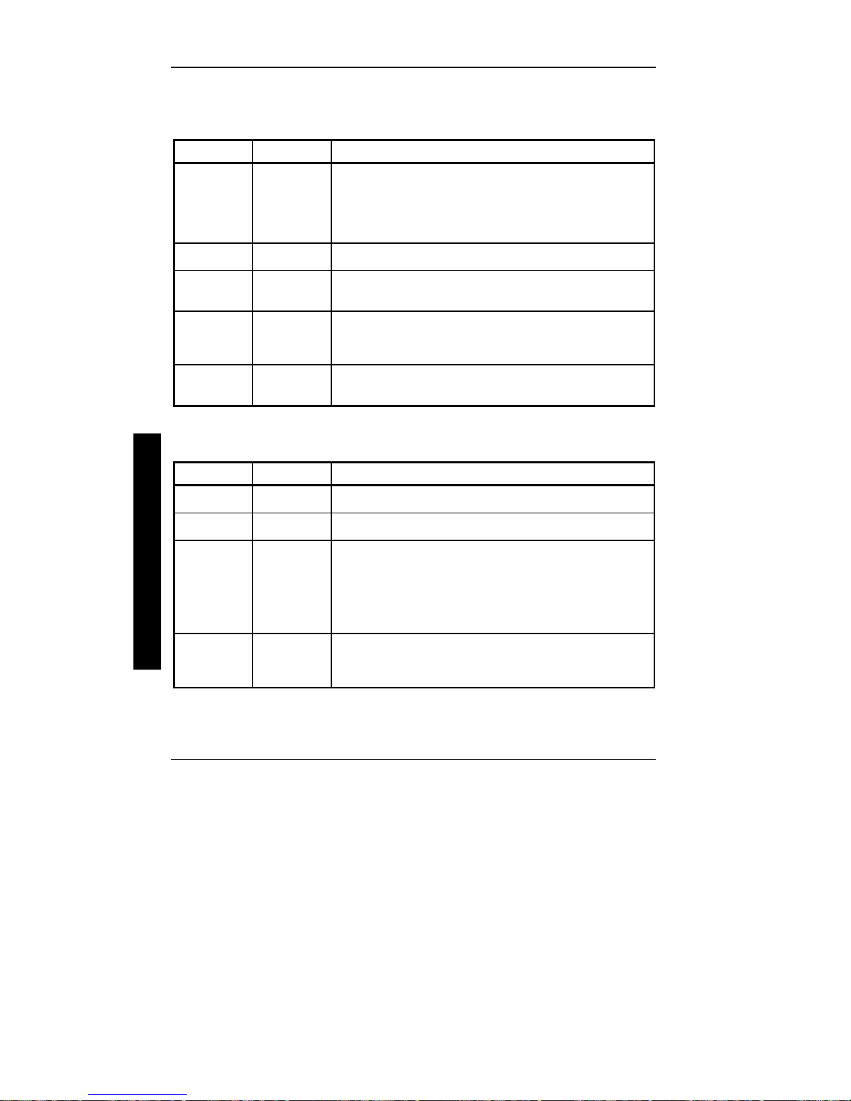
Menu Fields Settings Comments
System time
System date
Language
Diskette drive
A / Diskette
drive B
Video system
System
memory
Extended
memory
Current time Displays the current time.
Current date Displays the current date.
English This field only displays the current language of the BIOS.
1.44 MB, 3½
2.88 MB, 3½
Not Installed
1.2 MB, 5¼
720 KB, 3½
EGA / VGA
CGA 80x25
Monochrome
Not user
selectable
Not user
selectable
Sets the size and density of diskette drives.
Sets the video controller type.
Displays the amount of base (conventional) memory each time the
computer boots.
Displays the amount of extended memory each time the computer
boots.
Hard Disk Options
(IDE Adapter 0/1 Master/Slave)
Menu Fields Settings Comments
Autotype fixed
disk
Type
Cylinders
Heads
Sectors/track
Landing Zone
None to 39
User
0 to 4095 Displays the number of cylinders.
1 to 64 Displays the number of heads.
0 to 63 Displays the number of sectors/track.
0 to 4095 Displays the resting or park position of the heads when the HDD is
Press [Enter] to detect and fill in the installed hard disk drive
parameters in the remaining fields.
Selecting None to 39 automatically fills in the remaining fields in
this menu.
Selecting User allows the remaining fields to be filled in manually,
using the installed hard disk drive’s parameters.
inactive.
24 MCS Logistics Engineering - Nijmegen

Digital STARION 200i/300i PC Utilities & Configuration
Write
precomp
0 to 4095
None
Displays the number of cylinders that have their write timing
changed.
S
T
A
R
I
O
N
MCS Logistics Engineering - Nijmegen 25
2
0
0
i
3
0
0
Utilities & Configuration Digital STARION 200i/300i PC
Hard Disk Options
(IDE Adapter 0/1 Master/Slave)
Menu Fields Settings Comments
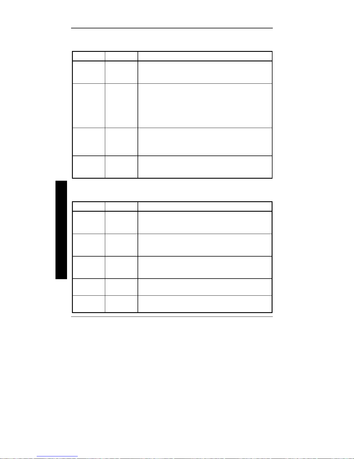
Multi-sector
transfers
LBA control
mode
32 Bit I/O
Transfer
Mode
Read Ahead
Mode
2 sectors
4 sectors
8 sectors
16 sectors
Auto
Disabled
Disabled
Enabled
Enabled
Disabled
Standard
Fast PIO1
Fast PIO2
Fast PIO3
Enabled
Disabled
(continued)
Determines the number of sectors per block for multiple sector
transfers.
Enabling LBA causes logical block addressing to be used instead of
cylinders, heads and sectors.
Enables or disables 32-Bit data transfer with the IDE HDD. If
enabled, Read Ahead Mode is also enabled and cannot be changed by
the user.
Selects the method to transfer data to and from the HDD. If autotype
is used to identify the HDD, Setup automatically selects the optimum
transfer mode.
When enabled, the read ahead buffer in the local bus IDE controller
increases HDD performance.
32-Bit I/O is enabled.
refers to the size the disk returns when queried.
Auto
Enabled
is selected automatically if
Memory and Cache
Menu Fields Settings Comments
Internal cache
External
cache
System BIOS
shadow
Cache system
BIOS
26 MCS Logistics Engineering - Nijmegen
Enabled
Disabled
Enabled
Disabled
Not user
selectable,
permanently set
to Enabled.
Enabled
Disabled
Enables or disables the computer's internal cache.
External cache is not present or upgradeable on STARION 200i/300i
systems.
The main logic board reserves an area of DRAM, called "shadow
memory" for a copy of system BIOS ROM. This DRAM is writeprotected and has the same addresses as the system BIOS ROM
locations. When system BIOS ROM is shadowed, the ROM
information is copied into an appropriate area in DRAM. This
increases the computer's performance because the system BIOS
instructions are in fast DRAM instead of ROM.
This option enables the system BIOS to be cached in the internal
cache and external cache (if installed). This increases computer
performance because BIOS instructions can be executed in cache
instead of RAM.

Digital STARION 200i/300i PC Utilities & Configuration
Video BIOS
shadow
Enabled
Disabled
The main logic board reserves an area of DRAM, called "shadow
Memory", for a copy of video BIOS ROM. This DRAM is writeprotected and has the same addresses as the video BIOS ROM
locations. When video BIOS ROM is shadowed, the ROM
information is copied into an appropriate area in DRAM. This
increases the computer's performance because the video BIOS
instructions are in fast DRAM instead of ROM. For PCI VGA cards,
video BIOS is always shadowed, regardless of this field’s setting.
S
T
A
R
I
O
N
MCS Logistics Engineering - Nijmegen 27
2
0
0
i
3
0
0
Utilities & Configuration Digital STARION 200i/300i PC
Memory and Cache (continued)
Menu Fields Settings Comments
Cache video
BIOS
Shadow 16K
at:
C8000h
CC000h
D0000h
D4000h
D8000h
DC000h
AT bus space
Extended
memory
report
Enabled
Disabled
Enabled
Disabled
Disabled Memory hole not available; upper memory is contiguous.
F80000h, 0.5MBSets the memory hole at address F80000 with 0.5 MB memory
F00000h, 1MBSets the memory hole at address F00000 with 1 MB memory
Compatibility
Noncompatibility
This option enables the video BIOS to be cached in the internal cache
and external cache (if installed). This increases computer
performance because video BIOS instructions can be executed in
cache instead of RAM.
Enables or disables shadowing of individual segments of ROM to
increase computer performance.
available.
available.
Selects the BIOS report mechanism for memory amount. Select
Compatibility when using a conventional operating system.
Select Non-compatibility for extended memory above 64 MB under
Windows NT v3.1.
Boot Options
Menu Fields Settings Comments
Boot sequence
SETUP
prompt
POST errors
Floppy check
Quiet boot
28 MCS Logistics Engineering - Nijmegen
A: only
A: then C:
C: then A:
C: only
Enabled
Disabled
Enabled
Disabled
Enabled
Disabled
Enabled
Disabled
Each time the computer boots, it will load the operating system from
the sequence selected.
Enables or disables the <F2> Setup prompt each time the computer
boots. Selecting Disable only disables the prompt indicating when to
press <F2> to enter Setup. Setup can still be entered by pressing <F2>
before POST completes.
Enabling this option causes the computer to pause and display a setup
entry or resume the boot prompt if an error occurs at boot. If this
option is disabled, the computer will always attempt to boot regardless
of a setup entry or error.
Enabling this option causes the computer to verify the diskette type
each time the computer boots. Disabling this option speeds up the
boot process.
Enabled inhibits the display of POST messages and instead displays
the Digital logo.
Disabled allows the display of POST messages when booting.

Digital STARION 200i/300i PC Utilities & Configuration
Summary
screen
Enabled
Disabled
Enabling this option causes the computer to display configuration
parameters (in the form of a summary screen) during boot.
S
T
A
R
I
O
N
MCS Logistics Engineering - Nijmegen 29
2
0
0
i
3
0
0
 Loading...