

Digital Equipment SF72, SF200 Owner's Manual

SF72StorageEnclosure
andSF200StorageArray
Owner’sManual
Order Number EK–SF72S–OM–001
Digital Equipment Corporation
First Edition, January 1991
The information in this document is subject to change without notice and should not
be construed as a commitment by Digital Equipment Corporation. Digital Equipment
Corporation assumes no responsibility for any errors that may appear in this document.
Restricted Rights: Use, duplication, or disclosure by the U. S. Government is subject to
restrictions as set forth in subparagraph ( c) (1 ) ( ii) of the Rights in Technical Data and
Computer Software clause at DFARS 252.227–7013.
Copyright © Digital Equipment Corporation 1991
All Rights Reserved.
Printed in U.S.A.
The postpaid Reader’s Comment Card included in this document requests the user’s
critical evaluation to assist in preparing future documentation.
FCC NOTICE: The equipment described in this manual generates, uses, and may emit
radio frequency energy. The equipment has been type tested and found to comply with
the limits for a Class A computing device pursuant to Subpart J of Part 15 of FCC
Rules, which are designed to provide reasonable protection against such radio frequency
interference when operated in a commercial environment. Operation of this equipment in
a residential area may cause interference, in which case the user at his own expense may
be required to take measures to correct the interference.
The following are trademarks of Digital Equipment Corporation:
DEC
PDP
VMS
DECUS TMSCP XMI
DSSI UNIBUS
KFMSA VAX
MSCP VAX 6000
This document was prepared and published by Educational Services Development and
Publishing, Digital Equipment Corporation.

Contents
About This Manual v
1 Introduction
1.1 SF200 Storage Array Overview . . . . . . . . . . . . . . . . . . . . . . . 1–1
1.2 SF72 Storage Enclosure Overview . . . . . . . . . . . . . . . . . . . . . 1–4
1.3 Related Documentation . . . . . . . . . . . . . . . . . . . . . . . . . . . . . 1–8
2 SF200 Storage Array Site Preparation
3 SF72 Storage Enclosure Operation
3.1 SF72 Configurations . . . . . . . . . . . . . . . . . . . . . . . . . . . . . . . 3–1
3.1.1 Through-Bus Mode . . . . . . . . . . . . . . . . . . . . . . . . . . . . . . . 3–3
3.1.2 Split-Bus Mode . . . . . . . . . . . . . . . . . . . . . . . . . . . . . . . . . 3–4
3.2 SF72 Front Panel Controls, Labels, and Indicators . . . . . . . . 3–5
3.2.1 SF72 OCP . . . . . . . . . . . . . . . . . . . . . . . . . . . . . . . . . . . . . 3–5
3.2.2 Drive DC Power Switches . . . . . . . . . . . . . . . . . . . . . . . . . 3–12
3.3 SF72 Rear Panel Controls and Indicators . . . . . . . . . . . . . . . 3–12
3.4 Applying Power to the Enclosure . . . . . . . . . . . . . . . . . . . . . . 3–15
3.5 Placing a Disk ISE On-Line . . . . . . . . . . . . . . . . . . . . . . . . . . 3–16
3.6 Taking a Disk ISE Off-Line . . . . . . . . . . . . . . . . . . . . . . . . . . 3–16
iii

iv Contents
4 Troubleshooting
4.1 Verifying a Hardware Problem . . . . . . . . . . . . . . . . . . . . . . . . 4–1
4.2 Recovering from a Disk ISE Fault Condition . . . . . . . . . . . . . 4–5
Glossary
Index
Figures
1–1 Front View of the SF200 Storage Array . . . . . . . . . . . . . . . . . 1–2
1–2 SF72 Storage Enclosure . . . . . . . . . . . . . . . . . . . . . . . . . . . . . 1–5
2–1 Single-Host System Configuration Sheet . . . . . . . . . . . . . . . . 2–2
2–2 Dual-Host System Configuration Sheet . . . . . . . . . . . . . . . . . 2–3
3–1 Single-Host Bus Configurations . . . . . . . . . . . . . . . . . . . . . . . 3–2
3–2 Dual-Host Bus Configurations . . . . . . . . . . . . . . . . . . . . . . . . 3–3
3–3 Through-Bus Mode . . . . . . . . . . . . . . . . . . . . . . . . . . . . . . . . . 3–4
3–4 Split-Bus Mode . . . . . . . . . . . . . . . . . . . . . . . . . . . . . . . . . . . 3–5
3–5 Front View of the SF72 Storage Enclosure . . . . . . . . . . . . . . . 3–6
3–6 SF72 Switchpacks . . . . . . . . . . . . . . . . . . . . . . . . . . . . . . . . . 3–9
3–7 SF72 Controls and Indicators . . . . . . . . . . . . . . . . . . . . . . . . . 3–11
3–8 Rear Panel of the SF72 Storage Enclosure . . . . . . . . . . . . . . . 3–13
4–1 Rear Panel of the SF72 Storage Enclosure . . . . . . . . . . . . . . . 4–2
4–2 Front Panel of the SF72 Storage Enclosure . . . . . . . . . . . . . . 4–3
Tables
1–1 SF200 Storage Array Specifications . . . . . . . . . . . . . . . . . . . . 1–3
1–2 SF72 Storage Enclosure Specifications . . . . . . . . . . . . . . . . . . 1–7
1–3 Related Documentation . . . . . . . . . . . . . . . . . . . . . . . . . . . . . 1–8
3–1 Summary of SF72 Front Panel Control/Indicator Functions . 3–7
3–2 DSSI ID Switch Settings (Single-Host) . . . . . . . . . . . . . . . . . 3–10
3–3 DSSI ID Switch Settings (Dual-Host) . . . . . . . . . . . . . . . . . . 3–10
3–4 Summary of SF72 Rear Panel Control/Indicator Functions . . 3–12

AboutThisManual
This manual is intended for users of the SF200 storage array and SF72
storage enclosure. This manual will provide users with all the information
they need to operate these devices in a safe and effective manner. The
information in this manual is organized as follows:
• Chapter 1, Introduction, contains a product description and
specifications for the SF200 storage array and SF72 storage enclosure.
• Chapter 2, Storage Array Site Preparation, contains site
preparation information for the SF200 storage array.
• Chapter 3, Storage Enclosure Operation, describes how to start
up the SF72 storage enclosure and how to bring the disk ISE on line
for normal operation.
• Chapter 4, Troubleshooting, contains simple instructions for
troubleshooting the installation of the SF200 storage array and SF72
storage enclosure.
v

1
Introduction
1.1 SF200 Storage Array Overview
The SF200 storage array is a storage rack cabinet designed to hold SF72
storage enclosures and magazine tape subsystems.
The SF200 storage array is intended to be installed in one or both sides
of a host system. All operator control panels (OCPs) project through the
front door of the storage array to allow easy access. The DSSI (Digital
Storage System Interconnect) cables from the host cabinet input/output
(I/O) panel connect to the DSSI I/O panel at the bottom rear of the storage
array. The DSSI I/O panel supports as many as 16 individual DSSI buses.
A fully configured single-host SF200 storage array uses four DSSI buses.
A fully configured dual-host SF200 storage array uses six DSSI buses.
The remaining unused DSSI buses are for future use.
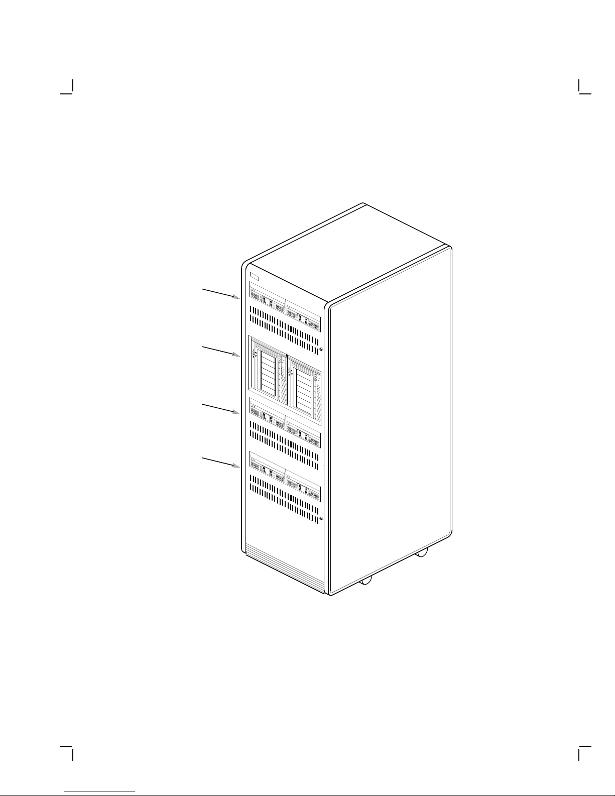
Viewing the SF200 storage array from the front, note that the SF72
storage enclosures and magazine tape subsystems are arranged in the
storage array as follows (Figure 1–1):
NOTE
The position numbers are visible on the right and left chassis side
rails when the front and rear doors of the storage array are open.
• Levels 1, 2, and 4 are reserved for SF72 storage enclosures only.
SF72 storage enclosure upgrades are installed into these levels in the
following order: position 1, 2, 3, 4, 7, and 8.
• Level 3 is reserved for magazine tape subsystems. Magazine tape
subsystem upgrades are installed into this level in the following order:
position 5 then 6.
Specifications for the SF200 storage array are shown in Table 1–1.
1–1
1–2 Introduction
LEVEL 4
LEVEL 3
LEVEL 2
LEVEL 1
SF200
0
1
2
3
4
5
6
0
1
2
3
4
5
6
Figure 1–1 Front View of the SF200 Storage Array
SHR_X1101_89

Introduction 1–3
Table 1–1 SF200 Storage Array Specifications
Characteristic Specification
Number of disk ISEs Minimum: 2, maximum: 24
Formatted storage capacity Minimum: 2, maximum: 24 (in 2 GByte
Dimensions (nominal) 152.4 cm (60.5 inches) H, 60.96 cm (24.0
Weight
Minimum configuration
Maximum configuration
1
2
Agency compliance FCC, UL, IEC, CSA, and VDE
Temperature +10°C to +40°C (+50°F to +104°F).
Humidity 10% to 85% @ maximum wet bulb
increments)
inches) W, 76.2 cm (34.0 inches) D
179.62 kg (396 lb)
442.25 kg (975 lb)
Derate 1.8°C for each 1000 meters altitude
(1.0°F for each 1000 feet altitude)
temperature of +32°C (+90°F) and
minimum dew point of +2°C (+36°F)
Recommended Environmental Limits
3
Operating environment
Temperature 18°C to 24°C (64.4°F to 75.2°F) with
an average rate of change of 3°C/hour
maximum and a step change of 3°C or less
Relative humidity 40% to 60% (noncondensing) with a step
change of 10% or less (noncondensing)
Altitude Up to 2400 meters (8000 feet)
Air quality (maximum
particle count)
Not to exceed 500,000 particles per cubic
foot of air at a size of 0.5 micron or larger
Air volume (at inlet) 50 cubic feet per minute (0.026 cubic
meters per second)
1
The minimum configuration is an SF200–Bx with one SF72–HK.
2
The maximum configuration is an SF200–Jx that consists of six SF72–JK enclosures and
two magazine tape subsystems.
3
These limits are for optimum equipment performance and reliability.

1–4 Introduction
Table 1–1 (Cont.) SF200 Storage Array Specifications
Characteristic Specification
Recommended Environmental Limits
Nonoperating environment
Temperature -40°C to +66°C (-40°F to +151°F)
Relative humidity 10% to 80%, noncondensing
Altitude 4900 meters (16,000 feet)
SF200 acoustic noise 6.8 bells
Nominal airflow through enclosure 360 to 520 cubic feet/minute
Input power requirements (47 to 63
Hz normal operation)
Power requirements during disk
ISE spinup
3
These limits are for optimum equipment performance and reliability.
6.00 A (per phase) @ 100 to 120 Vac (60
Hz), 3.00 A (per phase) @ 220 to 240 Vac
(50 Hz)
21.0 A @ 100 to 120 Vac (60 Hz),
10.5 A @ 220 to 240 Vac (50 Hz)
3
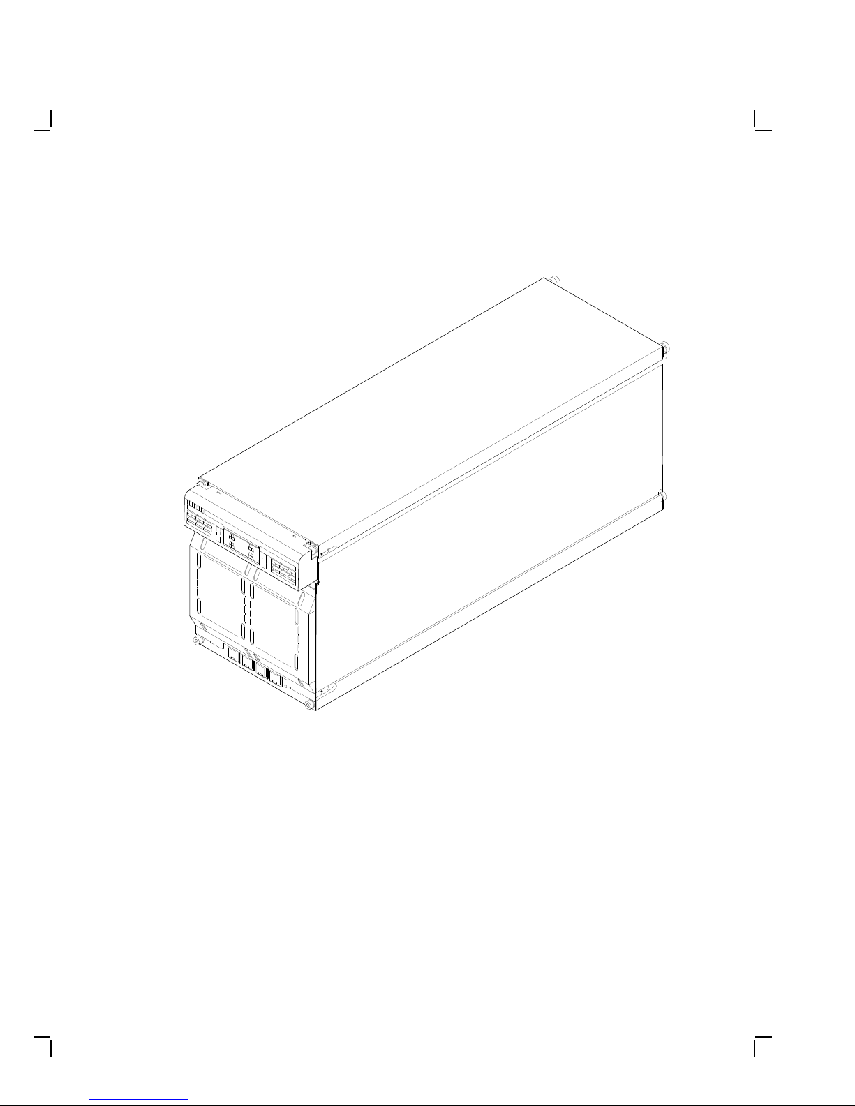
1.2 SF72 Storage Enclosure Overview
The SF72 is a storage enclosure designed to be installed into an SF200
storage array or certain system cabinets (Figure 1–2). A single enclosure
holds two or four RF72 disk integrated storage elements (ISEs). Each
disk ISE is independently controlled by the SF72 OCP. The power supply
in the enclosure provides the dc power and cooling for the disk ISEs.
Introduction 1–5
Figure 1–2 SF72 Storage Enclosure
SHR_X1123C_89

1–6 Introduction
The SF72 storage enclosure has the following features:
• The SF72 storage enclosure can operate in one of two modes:
through-bus (described in Section 3.1.1) or split-bus (described in
Section 3.1.2).
– When in through-bus mode, all of the disk ISEs connect to a
single common DSSI bus inside the SF72 enclosure. The DSSI
bus is terminated by connecting to one of the following: a DSSI
terminator (part number 12–31281–01), another SF72 storage
enclosure operating in the split-bus mode (while in singlehost configuration), or another host system (while in dual-host
configuration).
Host configurations are explained later in this manual. Refer to
the KFMSA Module Installation and User Manual for a more
detailed explanation.
– When in split-bus mode, the disk ISEs on the left side of the
enclosure connect to a different DSSI bus than the disk ISEs on
the right side. Also, both DSSI buses terminate inside the SF72
on the transition termination module (TTM) located behind the
OCP. By connecting one SF72 enclosure (operating in through-bus
mode) to an SF72 storage enclosure (operating in split-bus mode),
two DSSI buses with six disk ISEs each are obtained. This mode
of operation is used in single-host configurations only.
• Each RF72 disk ISE has its own set of switches and indicators on the
OCP.
• The enclosure power supply provides operating power to the
subassemblies of the enclosure. The rear panel of the power supply
contains the ac power switch for the SF72.
• Two DSSI connectors are at the top rear of the enclosure. The DSSI
bus runs to each disk ISE in the enclosure.
• The drive dc power switches for the disk ISEs are on the front panel
of the SF72 enclosure. Each switch contains a symbol to indicate its
associated disk ISE and an LED that lights when power is applied to
that disk ISE.
Specifications for the SF72 storage enclosure are shown in Table 1–2.

Introduction 1–7
Table 1–2 SF72 Storage Enclosure Specifications
Characteristic Specification
Number of disk ISE positions 4 (RF72 disk ISEs)
Formatted storage capacity
SF72–HK
SF72–JK
Dimensions (nominal) 26.7 cm (10.5 inches) H, 22.2 cm (8.75
Weight (nominal)
SF72–HK
SF72–JK
Agency compliance FCC, UL, IEC, CSA, and VDE
Temperature +10°C to +40°C (+50°F to +104°F).
Humidity 10% to 85% @ maximum wet bulb
1
2
2 GBytes
4 GBytes
inches) W, 71.1 cm (28.0 inches) D
1
2
34.93 kg (72 lb)
41.28 kg (91 lb)
Derate 1.8°C for each 1000 meters altitude
(1.0°F for each 1000 feet altitude)
temperature of +32°C (+90°F) and
minimum dew point of +2°C (+36°F)
Recommended Environmental Limits
3
Operating environment
Temperature 18°C to 24°C (64.4°F to 75.2°F) with
an average rate of change of 3°C/hour
maximum and a step change of 3°C or less
Relative humidity 40% to 60% (noncondensing) with a step
change of 10% or less (noncondensing)
Altitude Up to 2400 meters (8000 feet)
Air quality (maximum
particle count)
Not to exceed 500,000 particles per cubic
foot of air at a size of 0.5 micron or larger
Air volume (at inlet) 50 cubic feet per minute (0.026 cubic
meters per second)
1
The SF72–HK contains two RF72 disk ISEs.
2
The SF72–JK contains four RF72 disk ISEs.
3
These limits are for optimum equipment performance and reliability.

1–8 Introduction
Table 1–2 (Cont.) SF72 Storage Enclosure Specifications
Characteristic Specification
Recommended Environmental Limits
Nonoperating environment
Temperature -40°C to +66°C (-40°F to +151°F)
Relative humidity 10% to 80%, noncondensing
Altitude 4900 meters (16,000 feet)
SF72 enclosure acoustic noise 6.2 bells
Nominal airflow through enclosure 45 to 65 cubic feet/minute
Input power requirements (47 to 63
Hz normal operation)
Power requirements during disk
ISE spinup
3
These limits are for optimum equipment performance and reliability.
2.70 A @ 100 to 120 Vac (60 Hz),
1.20 A @ 220 to 240 Vac (50 Hz)
3.50 A @ 100 to 120 Vac (60 Hz),
3.25 A @ 220 to 240 Vac (50 Hz)
3
1.3 Related Documentation
Table 1–3 lists reference documentation that supplement this manual.
Table 1–3 Related Documentation
Title Order Number
KFMSA Module Installation and User Manual EK–KFMSA–IM
RF31/RF72 Integrated Storage Element User Guide EK–RF72D–UG
TF837 Magazine Tape Subsystem Service Manual EK–TF837–SM
 Loading...