

Digital Equipment SA7x Service Manual

SA7xEnclosure
ServiceManual
Order Number: EK–OSA7X–SM. C01
This manual explains how to operate, maintain, troubleshoot, and repair
the SA7x family of disk enclosures: the SA70, SA71, SA72, and SA73.
Digital Equipment Corporation
Maynard, Massachusetts

October 1993
While Digital believes the information included in this publication is correct as of the date of
publication, it is subject to change without notice.
Digital Equipment Corporation makes no representations that the interconnection of its products
in the manner described in this document will not infringe existing or future patent rights, nor
do the descriptions contained in this document imply the granting of licenses to make, use, or sell
equipment or software in accordance with the description.
NOTE: This equipment generates, uses, and may emit radio frequency energy. The equipment has
been type tested and found to comply with the limits for a Class A digital device pursuant to Part
15 of the FCC rules. These limits are designed to provide reasonable protection against harmful
interference in a commercial installation. This equipment generates, uses, and can radiate radio
frequency energy and, if not installed and used in accordance with the instruction manual, may
cause harmful interference to radio communications.
Any changes or modifications made to this equipment may void the user’s authority to operate the
equipment.
Operation of this equipment in a residential area may cause interference in which case the user,
at his own expense, will be required to take whatever measures may be required to correct the
interference.
Restricted Rights: Use, duplication, or disclosure by the U.S. Government is subject to restrictions
as set forth in subparagraph (c) (1) (ii) of the Rights in Technical Data and Computer Software
clause at DFARS 252.227-7013.
©Digital Equipment Corporation 1991, 1992, 1993.
All Rights Reserved.
Printed in the United States of America.
DEC, DSA, DSDF, HSC, HSC50, HSC70, KDA, KDA50, KDB50, KDM, MicroVAX, PDP-11, RA, SA,
SDI, UDA, UNIBUS, VAXsimPLUS, and the DIGITAL logo are trademarks of Digital Equipment
Corporation.
This document was prepared using VAX DOCUMENT Version 2.1.

Contents
Preface . . . . . . . . . . . . . . . . . . . . . . . . . . . . . . . . . . . . . . . . . . . . . . . . . . . . . . . . . . . . ix
1 Introducing the SA7x Enclosure
1.1 SA7x Enclosure Overview . . . . . . . . . . . . . . . . . . . . . . . . . . . . . . . . . . . . . 1–1
1.2 RA7x and SA7x Configurations . . . . . . . . . . . . . . . . . . . . . . . . . . . . . . . . . 1–6
1.3 SA7x Specifications . . . . . . . . . . . . . . . . . . . . . . . . . . . . . . . . . . . . . . . . . . 1–9
1.4 User Precautions . . . . . . . . . . . . . . . . . . . . . . . . . . . . . . . . . . . . . . . . . . . . 1–10
1.4.1 Data Recovery . . . . . . . . . . . . . . . . . . . . . . . . . . . . . . . . . . . . . . . . . . . 1–10
1.4.2 Recommended Operating Temperature . . . . . . . . . . . . . . . . . . . . . . . . 1–11
1.4.3 Electrostatic Discharge Protection . . . . . . . . . . . . . . . . . . . . . . . . . . . . 1–11
2 SA7x Technical Description
2.1 SA7x Chassis . . . . . . . . . . . . . . . . . . . . . . . . . . . . . . . . . . . . . . . . . . . . . . . 2–1
2.2 SA7x Frame . . . . . . . . . . . . . . . . . . . . . . . . . . . . . . . . . . . . . . . . . . . . . . . . 2–3
2.3 SA7x Fan Assembly . . . . . . . . . . . . . . . . . . . . . . . . . . . . . . . . . . . . . . . . . . 2–5
2.4 SA7x OCP and Transition Board Assembly . . . . . . . . . . . . . . . . . . . . . . . . 2–6
2.5 SA7x Power Supply . . . . . . . . . . . . . . . . . . . . . . . . . . . . . . . . . . . . . . . . . . 2–10
2.6 SA7x Enclosure Internal Cabling . . . . . . . . . . . . . . . . . . . . . . . . . . . . . . . . 2–14
3 Installing the SA7x
3.1 SA7x Installation Overview . . . . . . . . . . . . . . . . . . . . . . . . . . . . . . . . . . . . 3–1
3.1.1 Power and Safety . . . . . . . . . . . . . . . . . . . . . . . . . . . . . . . . . . . . . . . . . 3–1
3.1.2 Recording Disk Drive Serial Numbers . . . . . . . . . . . . . . . . . . . . . . . . . 3–1
3.2 Selecting Line Input Voltage . . . . . . . . . . . . . . . . . . . . . . . . . . . . . . . . . . . 3–2
3.3 Performing a Post-Installation Checkout and Power-Up . . . . . . . . . . . . . . 3–2
3.4 Setting Drive Unit Numbers . . . . . . . . . . . . . . . . . . . . . . . . . . . . . . . . . . . 3–5
3.5 Installing an Add-On SA7x Enclosure in an SA900 Storage Array . . . . . . 3–6
3.5.1 General Installation Considerations . . . . . . . . . . . . . . . . . . . . . . . . . . . 3–6
3.6 Preparing the SA900 Cabinet . . . . . . . . . . . . . . . . . . . . . . . . . . . . . . . . . . 3–9
3.7 Guide Rail Plate Installation . . . . . . . . . . . . . . . . . . . . . . . . . . . . . . . . . . . 3–11
3.8 Left Position Guide Rail Plate Installation . . . . . . . . . . . . . . . . . . . . . . . . 3–11
3.9 Right Position Guide Rail Plate Installation . . . . . . . . . . . . . . . . . . . . . . . 3–13
3.10 Preparing the SA7X Enclosure . . . . . . . . . . . . . . . . . . . . . . . . . . . . . . . . . . 3–14
3.11 Installing the SA7X Enclosure . . . . . . . . . . . . . . . . . . . . . . . . . . . . . . . . . . 3–15
3.11.1 Completing the Installation . . . . . . . . . . . . . . . . . . . . . . . . . . . . . . . . . 3–19
iii

4 Operating the SA7x
4.1 SA7x Switches and Indicators . . . . . . . . . . . . . . . . . . . . . . . . . . . . . . . . . . 4–1
4.1.1 Using the Switches and Indicators . . . . . . . . . . . . . . . . . . . . . . . . . . . . 4–1
4.1.2 Using Drive Power Switches and Indicators . . . . . . . . . . . . . . . . . . . . 4–4
4.2 Using SA7x Rear Panel Switches and Indicator . . . . . . . . . . . . . . . . . . . . . 4–5
4.3 Applying Power to the SA7x Enclosure . . . . . . . . . . . . . . . . . . . . . . . . . . . 4–6
4.4 Placing RA7x Drives On Line and Off Line . . . . . . . . . . . . . . . . . . . . . . . . 4–7
4.4.1 Placing a Drive On Line . . . . . . . . . . . . . . . . . . . . . . . . . . . . . . . . . . . . 4–7
4.4.2 Taking a Drive Off Line . . . . . . . . . . . . . . . . . . . . . . . . . . . . . . . . . . . . 4–8
5 Troubleshooting the SA7x
5.1 Identifying Problems . . . . . . . . . . . . . . . . . . . . . . . . . . . . . . . . . . . . . . . . . 5–1
5.2 Troubleshooting a Dead Enclosure . . . . . . . . . . . . . . . . . . . . . . . . . . . . . . . 5–1
5.2.1 If the Fault Indicator Is Lit . . . . . . . . . . . . . . . . . . . . . . . . . . . . . . . . . 5–1
5.2.2 If the Fault Indicator Is Not Lit . . . . . . . . . . . . . . . . . . . . . . . . . . . . . . 5–2
5.3 Troubleshooting a Flashing Drive Power Indicator . . . . . . . . . . . . . . . . . . 5–3
5.4 Troubleshooting Excessive Drive Errors or a Fault Condition . . . . . . . . . . 5–5
5.5 Reading OCP Error Codes . . . . . . . . . . . . . . . . . . . . . . . . . . . . . . . . . . . . . 5–5
5.6 Troubleshooting a Drive Not Visible to the Controller . . . . . . . . . . . . . . . . 5–6
5.7 Troubleshooting the OCP . . . . . . . . . . . . . . . . . . . . . . . . . . . . . . . . . . . . . . 5–6
6 Replacing RA7x Disk Drives
6.1 Installing and Removing an RA7x Disk Drive . . . . . . . . . . . . . . . . . . . . . . 6–2
6.1.1 Recording RA7x Disk Drive Serial Numbers . . . . . . . . . . . . . . . . . . . . 6–3
6.1.2 Reversing the RA70 Shoe Plate . . . . . . . . . . . . . . . . . . . . . . . . . . . . . . 6–4
6.1.3 Installing an RA7x Disk Drive . . . . . . . . . . . . . . . . . . . . . . . . . . . . . . . 6–6
6.1.4 Removing an RA7x Disk Drive . . . . . . . . . . . . . . . . . . . . . . . . . . . . . . . 6–6
6.2 Installing and Removing a Drive Position Filler . . . . . . . . . . . . . . . . . . . . 6–8
7 Replacing SA7x FRUs
7.1 Required Tools . . . . . . . . . . . . . . . . . . . . . . . . . . . . . . . . . . . . . . . . . . . . . . 7–2
7.2 Power Supply Removal and Installation . . . . . . . . . . . . . . . . . . . . . . . . . . 7–4
7.2.1 Removing the Power Supply . . . . . . . . . . . . . . . . . . . . . . . . . . . . . . . . 7–4
7.2.2 Installing the Power Supply . . . . . . . . . . . . . . . . . . . . . . . . . . . . . . . . . 7–4
7.3 OCP Removal and Installation . . . . . . . . . . . . . . . . . . . . . . . . . . . . . . . . . . 7–4
7.3.1 Removing the OCP . . . . . . . . . . . . . . . . . . . . . . . . . . . . . . . . . . . . . . . . 7–4
7.3.2 Installing the OCP . . . . . . . . . . . . . . . . . . . . . . . . . . . . . . . . . . . . . . . . 7–5
7.4 TB2 Removal and Installation . . . . . . . . . . . . . . . . . . . . . . . . . . . . . . . . . . 7–6
7.4.1 Removing Transition Board 2 . . . . . . . . . . . . . . . . . . . . . . . . . . . . . . . . 7–6
7.4.2 Installing Transition Board 2 . . . . . . . . . . . . . . . . . . . . . . . . . . . . . . . . 7–8
7.5 Transition Board 1 Removal and Installation . . . . . . . . . . . . . . . . . . . . . . 7–9
7.5.1 Removing Transition Board 1 . . . . . . . . . . . . . . . . . . . . . . . . . . . . . . . . 7–9
7.5.2 Installing Transition Board 1 . . . . . . . . . . . . . . . . . . . . . . . . . . . . . . . . 7–9
7.6 Fan Assembly Removal and Installation . . . . . . . . . . . . . . . . . . . . . . . . . . 7–10
7.6.1 Removing the Fan Assembly . . . . . . . . . . . . . . . . . . . . . . . . . . . . . . . . 7–10
7.6.2 Installing the Fan Assembly . . . . . . . . . . . . . . . . . . . . . . . . . . . . . . . . 7–10
7.7 Remote OCP Cable Removal and Installation . . . . . . . . . . . . . . . . . . . . . . 7–11
7.7.1 Removing a Remote OCP Cable . . . . . . . . . . . . . . . . . . . . . . . . . . . . . . 7–12
7.7.2 Installing a Remote OCP Cable . . . . . . . . . . . . . . . . . . . . . . . . . . . . . . 7–13
7.8 Power Harness Removal and Installation . . . . . . . . . . . . . . . . . . . . . . . . . 7–15
7.8.1 Removing a Power Harness . . . . . . . . . . . . . . . . . . . . . . . . . . . . . . . . . 7–15
iv

7.8.2 Installing a Power Harness . . . . . . . . . . . . . . . . . . . . . . . . . . . . . . . . . 7–16
7.9 SDI Cable Removal and Installation . . . . . . . . . . . . . . . . . . . . . . . . . . . . . 7–18
7.9.1 Removing an Enclosure SDI Cable . . . . . . . . . . . . . . . . . . . . . . . . . . . . 7–18
7.9.2 Installing an Enclosure SDI Cable . . . . . . . . . . . . . . . . . . . . . . . . . . . . 7–20
7.10 SA7x Checkout . . . . . . . . . . . . . . . . . . . . . . . . . . . . . . . . . . . . . . . . . . . . . . 7–20
A SA7x Internal Cabling
B Environmental Stabilization
C Part Numbers
D OCP Error Codes
E RA7x Error Rates
E.1 Type I Data Errors . . . . . . . . . . . . . . . . . . . . . . . . . . . . . . . . . . . . . . . . . . . E–1
E.2 Type II Data and Header Errors . . . . . . . . . . . . . . . . . . . . . . . . . . . . . . . . E–1
E.3 Loss-of-Positioner Errors . . . . . . . . . . . . . . . . . . . . . . . . . . . . . . . . . . . . . . E–2
E.4 Soft Errors . . . . . . . . . . . . . . . . . . . . . . . . . . . . . . . . . . . . . . . . . . . . . . . . . E–2
E.5 Unrecoverable Error (Hard Data Error) . . . . . . . . . . . . . . . . . . . . . . . . . . . E–2
E.6 Bad Block Replacement Rate . . . . . . . . . . . . . . . . . . . . . . . . . . . . . . . . . . . E–2
E.7 RA7x System Error Rates . . . . . . . . . . . . . . . . . . . . . . . . . . . . . . . . . . . . . E–2
F Revision Support
Index
Figures
1–1 SA7x Enclosure . . . . . . . . . . . . . . . . . . . . . . . . . . . . . . . . . . . . . . . . . . 1–2
1–2 RA70 Disk Drive . . . . . . . . . . . . . . . . . . . . . . . . . . . . . . . . . . . . . . . . . 1–3
1–3 RA71 Through RA73 Disk Drives . . . . . . . . . . . . . . . . . . . . . . . . . . . . 1–4
1–4 Using the ESD Grounding Strap . . . . . . . . . . . . . . . . . . . . . . . . . . . . . 1–12
2–1 SA70 Enclosure Assembly . . . . . . . . . . . . . . . . . . . . . . . . . . . . . . . . . . 2–2
2–2 Removing and Replacing a Disk Drive in the SA70 Enclosure . . . . . . . 2–4
2–3 SA7x Fan Assembly . . . . . . . . . . . . . . . . . . . . . . . . . . . . . . . . . . . . . . . 2–5
2–4 SA7x Enclosure Front Panel and OCP . . . . . . . . . . . . . . . . . . . . . . . . . 2–8
2–5 OCP, Transition Board Assembly, and Associated Circuits Block
Diagram . . . . . . . . . . . . . . . . . . . . . . . . . . . . . . . . . . . . . . . . . . . . . . . . 2–9
2–6 SA7x Enclosure Rear Panel and Power Supply . . . . . . . . . . . . . . . . . . 2–11
2–7 Power Supply Block Diagram . . . . . . . . . . . . . . . . . . . . . . . . . . . . . . . . 2–13
3–1 SA7x Enclosure Front Panel . . . . . . . . . . . . . . . . . . . . . . . . . . . . . . . . 3–4
3–2 Storage Device Add-On Sequence for the SA900 Storage Array (Front
View) . . . . . . . . . . . . . . . . . . . . . . . . . . . . . . . . . . . . . . . . . . . . . . . . . . 3–7
3–3 SA7x Front Clamping Assembly . . . . . . . . . . . . . . . . . . . . . . . . . . . . . 3–8
3–4 SA900 and SA7x Chassis Retaining Brackets . . . . . . . . . . . . . . . . . . . 3–9
3–5 SA7x Enclosure Guide Rail Assembly Installation . . . . . . . . . . . . . . . . 3–10
v

3–6 SA900 Mounting Rail Holes . . . . . . . . . . . . . . . . . . . . . . . . . . . . . . . . . 3–12
3–7 Installing the SA7x Enclosure in the SA900 . . . . . . . . . . . . . . . . . . . . 3–16
3–8 SA900 SDI Cable Connections . . . . . . . . . . . . . . . . . . . . . . . . . . . . . . . 3–18
3–9 SA900 Power Cords—SA7x Enclosures . . . . . . . . . . . . . . . . . . . . . . . . 3–20
4–1 SA7x Enclosure Front Panel . . . . . . . . . . . . . . . . . . . . . . . . . . . . . . . . 4–2
4–2 SA7x Enclosure Rear Panel . . . . . . . . . . . . . . . . . . . . . . . . . . . . . . . . . 4–6
5–1 SA7x Enclosure Front Panel . . . . . . . . . . . . . . . . . . . . . . . . . . . . . . . . 5–4
6–1 SA70 Enclosure . . . . . . . . . . . . . . . . . . . . . . . . . . . . . . . . . . . . . . . . . . 6–3
6–2 RA7x Disk Drive Serial Number Location . . . . . . . . . . . . . . . . . . . . . . 6–4
6–3 Reversing the RA7x Shoe Plate . . . . . . . . . . . . . . . . . . . . . . . . . . . . . . 6–5
6–4 Replacing RA70 Disk Drive . . . . . . . . . . . . . . . . . . . . . . . . . . . . . . . . . 6–7
7–1 SA7x Enclosure . . . . . . . . . . . . . . . . . . . . . . . . . . . . . . . . . . . . . . . . . . 7–2
7–2 Cabinet with Stabilizer Foot . . . . . . . . . . . . . . . . . . . . . . . . . . . . . . . . 7–3
7–3 SA7x Enclosure Rear Panel and Power Supply . . . . . . . . . . . . . . . . . . 7–5
7–4 Transition Board 2 . . . . . . . . . . . . . . . . . . . . . . . . . . . . . . . . . . . . . . . . 7–7
7–5 Removing TB1 . . . . . . . . . . . . . . . . . . . . . . . . . . . . . . . . . . . . . . . . . . . 7–8
7–6 Installing the Fan Assembly . . . . . . . . . . . . . . . . . . . . . . . . . . . . . . . . 7–11
7–7 Removing Acoustic Panels . . . . . . . . . . . . . . . . . . . . . . . . . . . . . . . . . . 7–13
7–8 Cable Routing . . . . . . . . . . . . . . . . . . . . . . . . . . . . . . . . . . . . . . . . . . . 7–14
7–9 SA7x Enclosure Power Harness . . . . . . . . . . . . . . . . . . . . . . . . . . . . . . 7–17
7–10 SA7x Enclosure Internal SDI Cables . . . . . . . . . . . . . . . . . . . . . . . . . . 7–19
A–1 SA7x Enclosure Cabling Block Diagram . . . . . . . . . . . . . . . . . . . . . . . A–2
A–2 Power Harness Cabling . . . . . . . . . . . . . . . . . . . . . . . . . . . . . . . . . . . . A–3
A–3 OCP to Transition Board Assembly to Disk Drive Cabling . . . . . . . . . . A–4
A–4 TB2 to Fan . . . . . . . . . . . . . . . . . . . . . . . . . . . . . . . . . . . . . . . . . . . . . . A–5
A–5 Rear Bulkhead to Drive SDI Connections . . . . . . . . . . . . . . . . . . . . . . A–6
A–6 4-Pin DC Power Connector . . . . . . . . . . . . . . . . . . . . . . . . . . . . . . . . . . A–7
Tables
1 Related Courses . . . . . . . . . . . . . . . . . . . . . . . . . . . . . . . . . . . . . . . . . . x
2 Related Documentation . . . . . . . . . . . . . . . . . . . . . . . . . . . . . . . . . . . . x
1–1 Authorized Disk Drive Installations . . . . . . . . . . . . . . . . . . . . . . . . . . . 1–1
1–2 RA7x Fixed Disk Configurations . . . . . . . . . . . . . . . . . . . . . . . . . . . . . 1–6
1–3 SA7x Configurations . . . . . . . . . . . . . . . . . . . . . . . . . . . . . . . . . . . . . . 1–7
1–4 SA7x Enclosure Recommended Environmental Limits . . . . . . . . . . . . . 1–9
1–5 SA7x Enclosure Specifications . . . . . . . . . . . . . . . . . . . . . . . . . . . . . . . 1–9
3–1 RA7x Drive Unit Numbers . . . . . . . . . . . . . . . . . . . . . . . . . . . . . . . . . 3–5
3–2 H9A00 External SDI Cables . . . . . . . . . . . . . . . . . . . . . . . . . . . . . . . . 3–17
4–1 SA7x Switch and Indicator Functions . . . . . . . . . . . . . . . . . . . . . . . . . 4–3
4–2 OCP Controls and Indicators . . . . . . . . . . . . . . . . . . . . . . . . . . . . . . . . 4–4
4–3 Power Supply Controls and Indicators . . . . . . . . . . . . . . . . . . . . . . . . . 4–5
5–1 SA7x Problems and Troubleshooting References . . . . . . . . . . . . . . . . . 5–1
6–1 Authorized Disk Drives Installations . . . . . . . . . . . . . . . . . . . . . . . . . . 6–1
A–1 Fan Connections . . . . . . . . . . . . . . . . . . . . . . . . . . . . . . . . . . . . . . . . . A–7
B–1 Thermal Stabilization Specifications . . . . . . . . . . . . . . . . . . . . . . . . . . B–1
C–1 SAxxx Cable Part Numbers . . . . . . . . . . . . . . . . . . . . . . . . . . . . . . . . . C–1
vi

C–2 H9A00 External SDI Cable Part Numbers . . . . . . . . . . . . . . . . . . . . . . C–1
C–3 SAxxx Assembly Part Numbers . . . . . . . . . . . . . . . . . . . . . . . . . . . . . . C–2
C–4 RA7x Part Numbers . . . . . . . . . . . . . . . . . . . . . . . . . . . . . . . . . . . . . . . C–2
D–1 OCP Error Codes . . . . . . . . . . . . . . . . . . . . . . . . . . . . . . . . . . . . . . . . . D–1
E–1 RA7x Error Rate Table . . . . . . . . . . . . . . . . . . . . . . . . . . . . . . . . . . . . . E–1
E–2 Allowable RA7x System Error Rate . . . . . . . . . . . . . . . . . . . . . . . . . . . E–3
F–1 VAX Diagnostics for RA71–RA73 Drives . . . . . . . . . . . . . . . . . . . . . . . F–1
F–2 Retired VAX Supervisor Programs . . . . . . . . . . . . . . . . . . . . . . . . . . . . F–2
F–3 Operating Systems for RA71–RA73 Drives . . . . . . . . . . . . . . . . . . . . . F–2
F–4 SDI Controllers for RA71–RA73 Drives . . . . . . . . . . . . . . . . . . . . . . . . F–2
vii


The SA7x Enclosure Service Manual explains how to install, operate,
troubleshoot, and perform field level repairs of the SA7x family of enclosures: the
SA70, SA71, SA72, and SA73. The manual is intended for Digital Multivendor
Customer Services engineers.
The SA70, SA71, SA72, and SA73 enclosures are physically identical. They are
differentiated only by the RA7x disk drives they contain:
• The SA70 accommodates one to four RA70 disk drives (280 MB each).
• The SA71 accommodates one to four RA71 disk drives (700 MB each).
• The SA72 accommodates one to four RA72 disk drives (1 GB each).
• The SA73 accommodates one to four RA73 disk drives (2 GB each).
Conventions
Special terminology used in the publication includes:
The term ‘‘SA7x’’ refers to the SA70, SA71, SA72, and SA73 enclosures
collectively.
The term ‘‘RA7x’’ refers to the RA70, RA71, RA72, and RA73 disk drives
collectively.
Preface
The following notations are used in this manual:
• Note—Identifies information that is of special interest.
• CAUTION—Identifies information that pertains to the protection of the
equipment or loss of data.
• WARNING—Identifies information that pertains to your safety.
ix

Related Courses and Documentation
Table 1 lists the Digital courses related to the SA7x enclosure.
Table 1 Related Courses
Title Order Number
AC Power & Grounding EY–B730–PO
DSA Architecture Level 1 Course EY–5593E–IV
Electrical Safety EY–B737E–PO
Electrical Safety and Lockout/Tagout Procedures EY–E038E–SO
RA70/BA27 Disk Drive Maintenance Course EY–5805E–IV
VAXsimPLUS Maintenance Course EY–7687E–PO
Table 2 lists the documentation related to the SA7x enclosure.
Table 2 Related Documentation
Document Title
DSA Troubleshooting Flowchart EK–DSATF–TM
Disk Drive Technical Description Manual EK–ORA70–TD
BA27 Maintenance Print Set MP–01429
SAxxx Configuration Guide EK-SAXXX–CG
RA7x Disk Drive Service Manual EK–ORA7X–SM
RA7x/SA7x Pocket Reference Guide EK–RSA7X–PG
RA70 Field Maintenance Print Set MP–01428
RA71/RA72 Support Print Set EM–01434
RA71/RA72 Field Maintenance Print Set MP–01434
RA73 Support Print Set EM–01439
RA73 Field Maintenance Print Set MP–01439
SA7x Enclosure User Guide EK–OSA7X–UG
SA7x Support Print Set EM–01435
SA7x Field Maintenance Print Set MP–01435
Document Order
Number
x

Introducing the SA7x Enclosure
This chapter is an overview of the SA7x enclosure, lists SA7x configurations and
specifications, and discusses user precautions.
1.1 SA7x Enclosure Overview
The term ‘‘SA7x’’ refers to the family of enclosures that includes:
• The SA70—Accommodates one to four RA70 disk drives (280 MB each)
• The SA71—Accommodates one to four RA71 disk drives (700 MB each)
• The SA72—Accommodates one to four RA72 disk drives (1 GB each)
• The SA73—Accommodates one to four RA73 disk drives (2 GB each)
For all of these designations, the enclosure itself is physically identical. What
differentiates an SA70 enclosure from an SA71 enclosure is the type of drives
installed in each (RA70s and RA71s). See Figure 1–1 for an illustration of an
SA7x enclosure.
Table 1–1 lists the the types of disk drives that are authorized for installation in
each SA7x enclosure.
1
Table 1–1 Authorized Disk Drive Installations
Enclosure RA70 RA71 RA72 RA73
SA70 Yes No No No
SA71 Yes Yes Yes Yes
SA72 Yes Yes Yes Yes
SA73 Yes Yes Yes Yes
1
A maximum of three drives may be installed.
The SA7x enclosure provides mounting space, power, cooling, and control for up
to four RA7x disk drives. Each disk drive is independently powered and operated
by the enclosure.
The enclosure is installed as a component in a storage array cabinet.
The RA7x disk drive used in the SA7x enclosure is a random-access Winchester
technology drive with a formatted storage capacity of 280 MB to 2 GB. The drive
features modular components that can be replaced with minimum down time.
Figure 1–2 shows an RA70 disk drive. Figure 1–3 shows an RA71 through RA73
disk drive.
1
1
Introducing the SA7x Enclosure 1–1
Introducing the SA7x Enclosure
1.1 SA7x Enclosure Overview
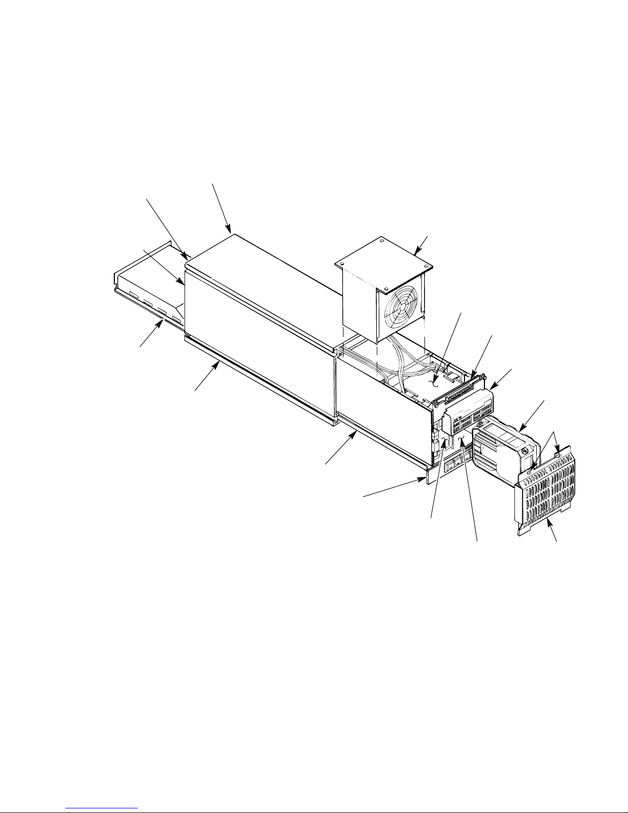
Figure 1–1 SA7x Enclosure
RIGHT REAR
LEFT REAR
DISK DRIVE
POSITION
REAR
COVER
(NOT
SHOWN)
POWER
SUPPLY
DISK DRIVE
POSITION
CHASSIS
FAN
TRANSITION
BOARD 2
TRANSITION
BOARD 1
OPERATOR
CONTROL
PANEL
RA70 DISK
DRIVE SHOWN
MOUNTING
SCREWS
FRAME
DRIVE POWER
SWITCH PANEL
LEFT FRONT
DISK DRIVE
POSITION
RIGHT FRONT
DISK DRIVE
POSITION
FRONT
COVER
CXO-1845D_S
You can combine SA7x enclosures into shadow sets. When using shadow sets,
remember that when replacing the power supply or transition boards 1 or 2, you
need to remove the power from the enclosure.
RA7x disk drive can be used with any disk drive controller using a standard
disk interface (SDI), including KDA50, KDB50, or KDM50 controller modules,
hierarchical storage controllers (HSCs), and UDA controllers. The drive is
compatible with the Digital Storage Architecture (DSA) and Mass Storage Control
Protocol (MSCP).
1–2 Introducing the SA7x Enclosure
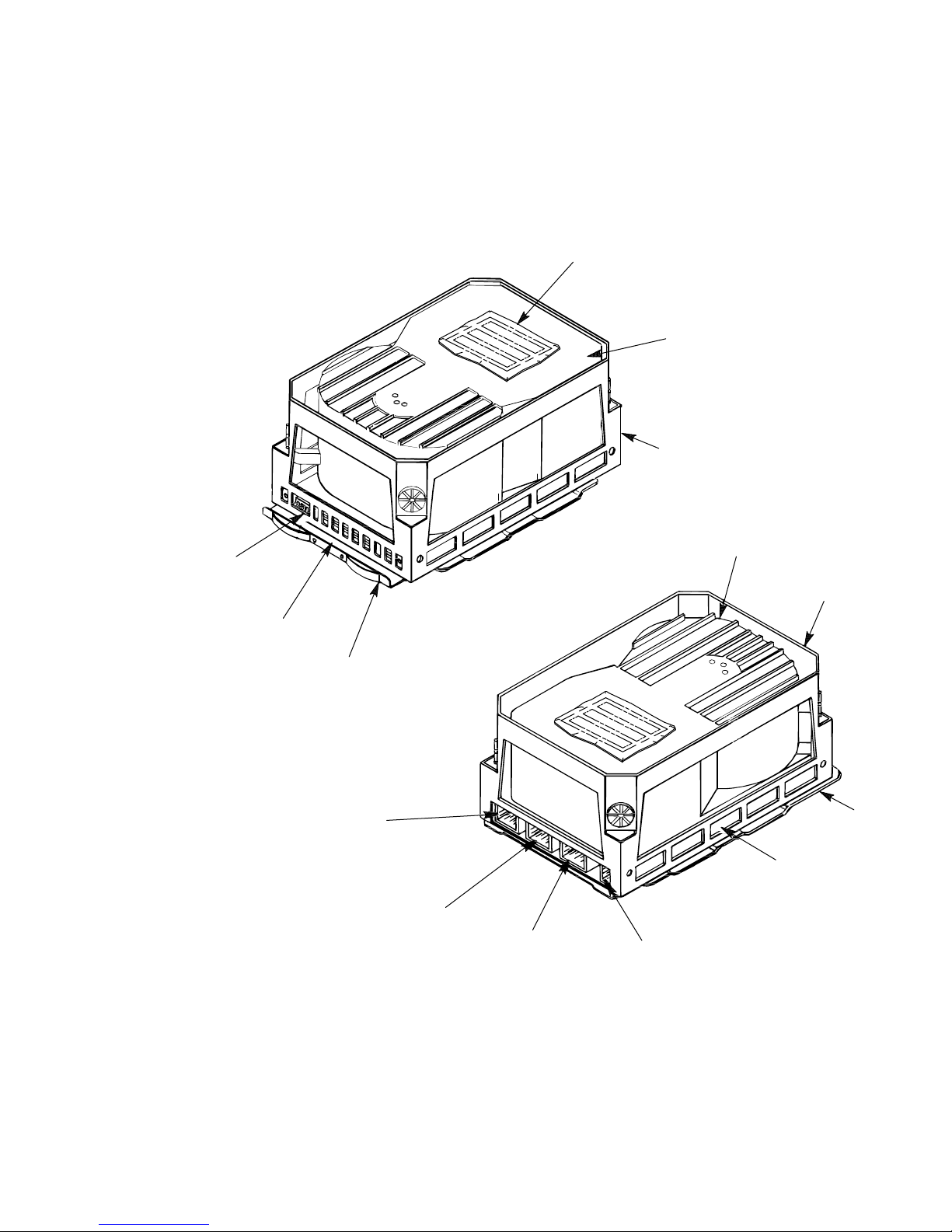
Figure 1–2 RA70 Disk Drive
Introducing the SA7x Enclosure
1.1 SA7x Enclosure Overview
SERIAL
NUMBER
LABEL
HDA
CHASSIS
FRONT PANEL
CONTROLS AND
INDICATORS
SERIAL
NUMBER
LOCATION
SHOE
PLATE
J4 4-PIN
POWER
J3 20-PIN REMOTE
OPERATOR CONTROL
PANEL CONNECTOR
J2 8-PIN SDI
CONNECTOR
(PORT B)
HDA
CHASSIS
SHOE
PLATE
ELECTRONIC
CONTROL
MODULE (ECM)
SET
J1 8-PIN SDI
CONNECTOR
(PORT A)
CXO-1878B_S
Introducing the SA7x Enclosure 1–3
Introducing the SA7x Enclosure
1.1 SA7x Enclosure Overview
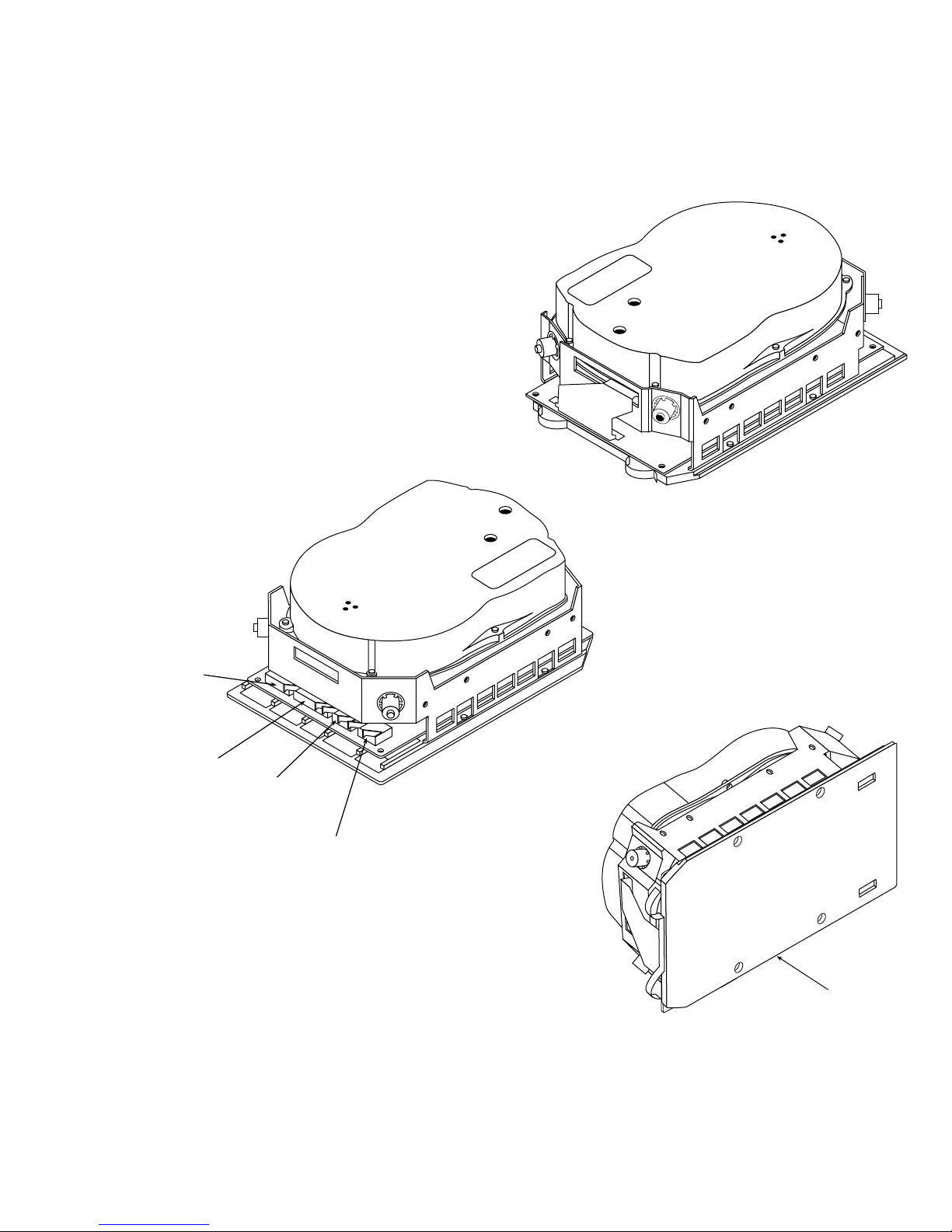
Figure 1–3 RA71 Through RA73 Disk Drives
FRONT VIEW
4-PIN
POWER
20-PIN
OCP
8-PIN
SDI-PORT B
8-PIN
SDI-PORT A
REAR VIEW
BOTTOM VIEW
SHOE
PLATE
CXO-3518A-MC
1–4 Introducing the SA7x Enclosure

Introducing the SA7x Enclosure
1.1 SA7x Enclosure Overview
The major subassemblies of the SA7x enclosure are:
• Chassis
• Frame
• Operator control panel (OCP)
• Transition board 1 (TB1)
• Transition board 2 (TB2)
• Power supply
• Fan assembly
• Enclosure-internal cables
Figure 1–1 shows the major subassemblies of the SA7x enclosure. Except for the
RA70 disk drive description, Figure 1–1 is accurate for all SA7x enclosures.
The frame slides into the chassis and contains the mounting facilities for the
other subassemblies. The disk drives fit into recesses located in the front and
rear of the frame. The OCP is mounted above the front disk drives and plugs
into TB1. TB1 interfaces the OCP to TB2. TB2 is located above the front disk
drives and interfaces drive signals through TB1 to the OCP. The power supply
is located in the rear of the frame, below the rear disk drives. The fan assembly
is fitted into the central portion of the frame. Interconnecting cables for the
subassemblies run along the outer sides of the frame behind acoustic paneling.
RA7x disk drives may be mounted in any of the four disk drive positions.
Installation procedures suggest to install the first two drives in the rear positions
and the second two drives in the front positions.
Caution
The SA7x enclosure will accommodate a single RA7x disk drive. However,
if only one drive is installed in the enclosure, a drive position filler is
required to route cooling air and prevent overheating. See Section 6.2 for
instructions on installing and removing a drive position filler.
The disk drive is installed in an enclosure with the rear panel of the drive, which
contains interface connectors, facing outward. The drives are operated from four
sets of switches and indicators on the enclosure OCP, one set for each disk drive
in the enclosure.
SDI bus cables from the disk drives are routed inside the enclosure to a cable
bulkhead at the top rear of the enclosure.
The enclosure power supply provides operating power to the major subassemblies
of the enclosure. The rear panel of the power supply contains the Master On/Off
switch for the enclosure.
Each RA7x disk drive is powered and controlled independently. A drive can be
operated with other disk drive positions unoccupied or while maintenance is
being performed on another drive. The power switches for the disk drives are
located on the front panel of the enclosure. Each drive power switch contains a
symbol to indicate its associated drive and an indicator that lights when power is
applied to the drive.
Introducing the SA7x Enclosure 1–5

Introducing the SA7x Enclosure
1.1 SA7x Enclosure Overview
The fan assembly circulates cooling air throughout the frame of the SA7x
enclosure. The air is drawn in through holes in the front panel on the enclosure
and is exhausted through holes in the rear panel.
The SA7x enclosure meets the following environmental and safety standards:
• DEC Standard 102 for environment
• DEC Standard 103 for electromagnetic emissions
• DEC Standard 104 for computer room noise level
• DEC Standard 119 for product safety
• National and international regulatory agency requirements, including FCC,
UL, IEC, CSA, and VDE
Your Digital sales representative can answer specific questions related to the
various environmental and safety standards.
1.2 RA7x and SA7x Configurations
Tables 1–2 and 1–3 show authorized RA7x disk drive and SA7x enclosure
configurations.
The description column of the RA7x configuration table contains the following
information:
Authorized installation:
Factory installation—Only installed at the factory.
Field add-on—Only installed in the field.
Enclosure:
Enclosures in which the disk drive may be installed.
Table 1–2 RA7x Fixed Disk Configurations
Formatted
RA7x Disk
Drive Description
RA70–A Field add-on: SA70 options in storage arrays. 0.28 GB
RA70E–SA Factory installation: MicroVAX 3500, 3600, and 3900 0.28 GB
RA70E–SF Field add-on: MicroVAX 3500, 3600, and 3900 0.28 GB
RA71–AF Factory installation: SA71 enclosure 0.70 GB
RA71–AK Field add-on: SA71 enclosure 0.70 GB
RA72–AF Factory installation: SA71 enclosure 1.0 GB
RA72–AK Field add-on: SA72 enclosure 1.0 GB
RA73–AF Factory installation: SA73 enclosure 2.0 GB
RA73–AK Field add-on: SA73 enclosure 2.0 GB
Storage
Capacity
The description column of the SA7x configuration table contains the following
information:
Authorized installation:
Factory installation—Only installed at the factory.
Field add-on—Only installed in the field.
1–6 Introducing the SA7x Enclosure

Storage Array:
Systems and storage arrays in which the disk drive or enclosure may be
installed.
Table 1–3 SA7x Configurations
Enclosure Description
RA70
Disk
Drive
Introducing the SA7x Enclosure
1.2 RA7x and SA7x Configurations
RA71
Disk
Drive
RA72
Disk
Drive
RA73
Disk
Drive
Formatted
Storage
Capacity
SA70–HK Field add-on
SA550/SA650/SA850
1
120-240 Vac, 50-60 Hz
SA70–JK Field add-on
SA550/SA650/SA850
1
120-240 Vac, 50-60 Hz
SA70–LK Storage array building block
DECsystem 5800/VAX 6000
120-240 Vac, 50-60 Hz
SA70–MK Storage array building block
DECsystem 5800/VAX 6000
120-240 Vac, 50-60 Hz
SA71–CK Field add-on
SA550/SA650/SA850
120-240 Vac, 50-60 Hz
SA71–EK Field add-on
SA900
120-240 Vac, 50-60 Hz
SA71–FK Field add-on
SA900
120-240 Vac, 50-60 Hz
SA71–GK Factory installation
SA900
120-240 Vac, 50-60 Hz
SA71–HK Factory installation
SA900
120-240 Vac, 50-60 Hz
SA71–JK Field add-on
SA550/SA650/SA850
120-240 Vac, 50-60 Hz
SA71–LK Field add-on
SA600/SA800
120-240 Vac, 50-60 Hz
SA71–MK Field add-on
SA600/SA800
120-240 Vac, 50-60 Hz
SA72–CK Field add-on
SA550/SA650/SA850
120-240 Vac, 50-60 Hz
2 0 0 0 0.56 GB
4 0 0 0 1.12 GB
2
2
2 0 0 0 0.56 GB
4 0 0 0 1.12 GB
0 1 0 0 0.70 GB
0 1 0 0 0.70 GB
0 4 0 0 2.8 GB
0 1 0 0 0.70 GB
0 4 0 0 2.8 GB
0 4 0 0 2.8 GB
0 1 0 0 0.70 GB
0 4 0 0 2.8 GB
0 0 1 0 1.0 GB
1
To install in an SA600 or SA800 storage array first upgrade the storage array as described in Chapter 5.
2
Adding the first SA7x to a VAX 6000 or DECsystem 5800 system without internal storage devices requires an upgrade
kit:
60 Hz system—Upgrade Kit 62X34–UA
50 Hz system—Upgrade Kit 62X34–UB
Continued on next page
Introducing the SA7x Enclosure 1–7

Introducing the SA7x Enclosure
1.2 RA7x and SA7x Configurations
Table 1–3 (Continued) SA7x Configurations
Enclosure Description
SA72–EK Field add-on
SA900
120-240 Vac, 50-60 Hz
SA72–FK Field add-on
SA900
120-240 Vac, 50-60 Hz
SA72–GK Factory installation
SA900
120-240 Vac, 50-60 Hz
SA72–HK Factory installation
SA900
120-240 Vac, 50-60 Hz
SA72–JK Field add-on
SA550/SA650/SA850
120-240 Vac, 50-60 Hz
SA72–LK Field add-on
SA600/SA800
120-240 Vac, 50-60 Hz
SA72–MK Field add-on
SA600/SA800
120-240 Vac, 50-60 Hz
SA73–CK Field add-on
SA550/SA650/SA850
120-240 Vac, 50-60 Hz
SA73–EK Field add-on
SA900
120-240 Vac, 50-60 Hz
SA73–FK Field add-on
SA900
120-240 Vac, 50-60 Hz
SA73–GK Factory installation
SA900
120-240 Vac, 50-60 Hz
SA73–HK Factory installation
SA900
120-240 Vac, 50-60 Hz
SA73–JK Field add-on
SA550/SA650/SA850
120-240 Vac, 50-60 Hz
SA73–LK Field add-on
SA600/SA800
120-240 Vac, 50-60 Hz
SA73–MK Field add-on
SA600/SA800
120-240 Vac, 50-60 Hz
RA70
Disk
Drive
0 0 1 0 1.0 GB
0 0 4 0 4.0 GB
0 0 1 0 1.0 GB
0 0 4 0 4.0 GB
0 0 4 0 4.0 GB
0 0 0 1 1.0 GB
0 0 4 0 4.0 GB
0 0 1 0 2.0 GB
0 0 0 1 2.0 GB
0 0 0 4 8.0 GB
0 0 0 1 2.0 GB
0 0 0 4 8.0 GB
0 0 0 4 8.0 GB
0 0 0 1 2.0 GB
0 0 0 4 8.0 GB
RA71
Disk
Drive
RA72
Disk
Drive
RA73
Disk
Drive
Formatted
Storage
Capacity
1–8 Introducing the SA7x Enclosure

Introducing the SA7x Enclosure
1.3 SA7x Specifications
1.3 SA7x Specifications
Recommended environmental limits for operating the SA7x enclosure are listed in
Table 1–4. General specifications for the SA7x enclosure are shown in Table 1–5.
Caution
For the SA7x enclosure and installed RA7x disk drives to perform at
the optimal level and maintain high reliability, they should be used in
environments recommended in the following tables.
Table 1–4 SA7x Enclosure Recommended Environmental Limits
Characteristic Min. Max. Units
Operating temperature 65
18
Operating temperature rate of change – 5.4
Operating temperature step change – 5.4
Operating relative humidity 40 60 Percent relative humidity
Operating relative humidity rate of change – 10 Percent relative humidity
Storage temperature 65
18
Storage humidity – 50 Percent relative humidity
75
24
3
3
85
29
Degrees Fahrenheit
Degrees Celsius
Degrees per hour Fahrenheit
Degrees per hour Celsius
Degrees per hour Fahrenheit
Degrees per hour Celsius
(noncondensing)
(noncondensing) per hour
Degrees Fahrenheit
Degrees Celsius
(noncondensing)
Table 1–5 SA7x Enclosure Specifications
Characteristic Specification
Number of disk drive positions Four
Maximum formatted storage capacity:
SA70 enclosure
SA71 enclosure
SA72 enclosure
SA73 enclosure
Dimensions (nominal) 26.7 cm (10.5 in) high
Weight (nominal):
SA70 enclosure
SA71, SA72, or SA73 enclosures
1.12 GB
2.8 GB
4.0 GB
8.0 GB
22.2 cm (8.75 in) wide
71.1 cm (28 in) deep
21 kg (46 lb) empty
40 kg (88 lb) with four disk drives
21 kg (46 lb) empty
31.7 kg (72 lb) with four disk drives
Continued on next page
Introducing the SA7x Enclosure 1–9

Introducing the SA7x Enclosure
1.3 SA7x Specifications
Table 1–5 (Continued) SA7x Enclosure Specifications
Characteristic Specification
Operating temperature +10° C to +40° C (+50° F to +104°
Operating humidity 10% to 85% @ maximum wet bulb
Operating altitude Up to 2,400 m (8,000 ft)
Nonoperating temperature -40° C to +66° C (-40° F to +151° F)
Nonoperating relative humidity 8% to 80% relative humidity,
Nonoperating altitude 4,900 m (16,000 ft)
Shock and vibration Complies with DEC Standard 102
Enclosure acoustic noise
(with four RA7x disk drives)
Fan operating parameters:
Low speed operation Below +28° C (+82° F), +/- 1° C (1.8°
High speed operation Above +30° C (+86° F), +/- 1° C (1.8°
Nominal airflow through the enclosure Between 45 and 65 cubic ft per
Input power requirements (47 to 63 Hz) 4.6 A @ 100 to 120 Vac (60 Hz), 2.3 A
F). Derate 1.8° C for each 1,000 m
altitude or 1.0° F for each 1,000 ft
altitude.
temperature +32° C (+90° F) and
minimum dew point of +2° C (+36° F)
noncondensing
Complies with DEC Standard 102
F)
F)
minute
@ 220 to 240 Vac (50 Hz)
1.4 User Precautions
Digital recommends that certain precautions be taken to protect equipment and
user data. These precautions involve backup methods, recommended operating
temperatures, and electrostatic discharge (ESD) protection, all of which are
discussed in this section.
1.4.1 Data Recovery
Data is not recoverable from an inoperable head disk assembly (HDA). Therefore,
it is your responsibility to make sure data is protected using proper backup
procedures. Digital recommends the following backup methods for RA7x disk
drives:
• File duplication—This method normally involves copying data onto removable
media, such as magnetic tape.
• Journaling—This method is recommended for files in a transaction processing
application. Journaling allows reconstruction of files up to the last checkpoint
or backup.
1–10 Introducing the SA7x Enclosure

1.4.2 Recommended Operating Temperature
The SA7x enclosure and its installed drives can operate within a temperature
range of +10° to +40° C (+50° to +104° F). However, Digital recommends that the
enclosure and its drives be operated in a temperature range of +18° to +24° C
(+64° to +75° F) to increase reliability and product life.
Caution
Disk drives and enclosures must be environmentally stabilized in their
protective barrier bags at the installation site. Failure to environmentally
stabilize the equipment may result in damage to the drive media or
electronic components. For more information about environmental
stabilization, see Appendix B.
1.4.3 Electrostatic Discharge Protection
Electrostatic discharge (ESD) is caused by the buildup and release of static
electricity. An electrical charge from a person or object can damage hardware
components and result in premature device or option failure.
Observe the following guidelines when handling static-sensitive components:
Introducing the SA7x Enclosure
1.4 User Precautions
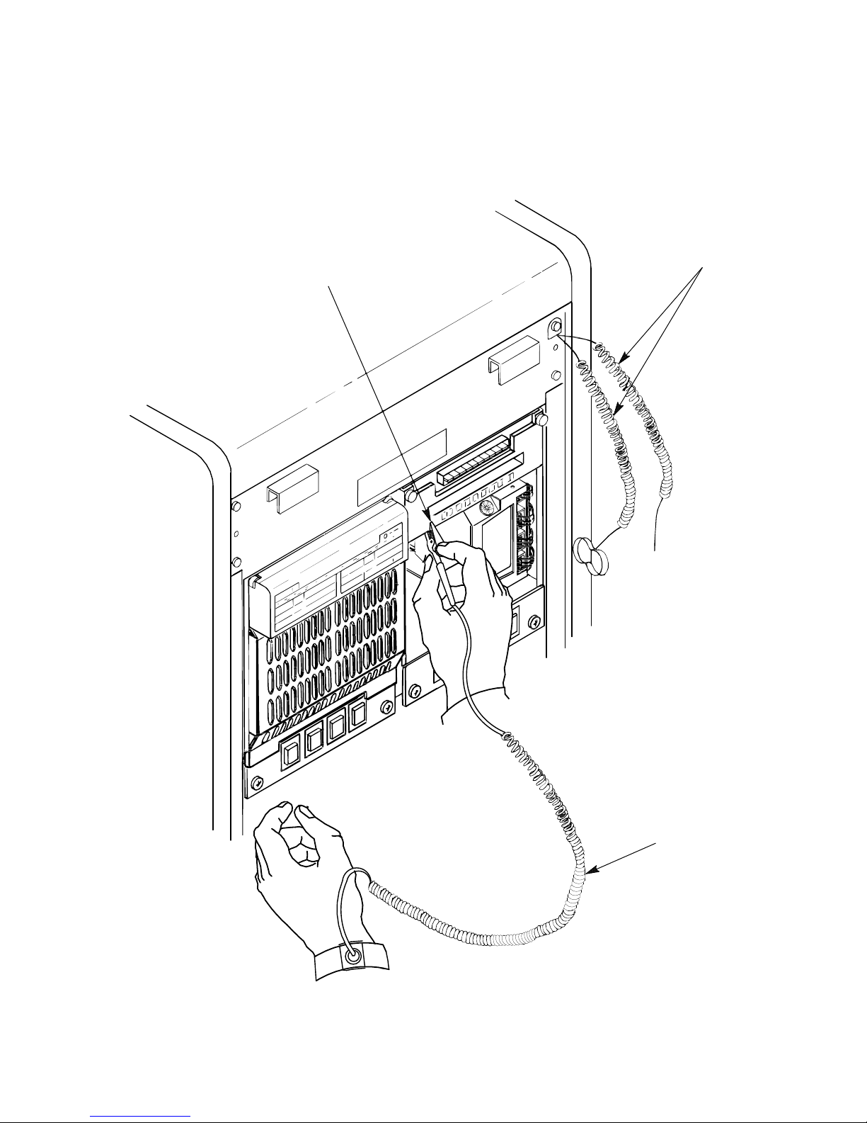
1. Read all instructions and installation procedures included with static control
materials.
2. Wear a properly grounded ESD wrist strap. (See Figure 1–4.)
When using an ESD wrist strap:
• Ensure that the wrist strap fits snugly for proper conductivity.
• Connect the alligator clip securely to a clean, unpainted, grounded metal
surface, such as the drive or cabinet chassis.
• Do not overextend the grounding cord.
3. Use static-protective containers to transfer modules and components.
Introducing the SA7x Enclosure 1–11
Introducing the SA7x Enclosure
1.4 User Precautions
Figure 1–4 Using the ESD Grounding Strap
ESD GROUNDING STRAP
GROUNDED TO SA7x
ENCLOSURE CHASSIS
ESD GROUNDING
STRAP SUPPLIED
WITH 60-INCH CABINET
1–12 Introducing the SA7x Enclosure
OPERATOR’S ESD
GROUNDING STRAP
CXO-2609B_S

This chapter describes the following major components of the SA7x enclosure:
• Chassis
• Frame
• Fan assembly
• Operator control panel (OCP)
• Transition board assembly (TB1 and TB2)
• Power supply
• Enclosure-internal cabling
Figure 2–1 shows the SA7x enclosure with RA70 disk drives. The SA71, SA72,
and SA73 enclosures are virtually identical; they all have either an RA71, RA72,
or RA73 disk drive installed.
2.1 SA7x Chassis
The SA7x chassis is made of extruded aluminum with a protective finish.
2
SA7x Technical Description
The enclosure uses the paired upper and lower grooves on each side of the chassis
for mounting the cabinet uprights. Each side is identical, so the enclosure may be
mounted with either its left or right side facing the cabinet uprights.
The power supply slides on rails in the lower-rear portion of the chassis.
Matching rails in the upper half of the chassis are not functional.
SA7x Technical Description 2–1

SA7x Technical Description
2.1 SA7x Chassis
Figure 2–1 SA70 Enclosure Assembly
RIGHT REAR
LEFT REAR
DISK DRIVE
POSITION
REAR
COVER
(NOT
SHOWN)
POWER
SUPPLY
DISK DRIVE
POSITION
CHASSIS
FAN
TRANSITION
BOARD 2
TRANSITION
BOARD 1
OPERATOR
CONTROL
PANEL
RA70 DISK
DRIVE SHOWN
FRAME
DRIVE POWER
SWITCH PANEL
LEFT FRONT
DISK DRIVE
POSITION
RIGHT FRONT
DISK DRIVE
POSITION
MOUNTING
SCREWS
FRONT
COVER
CXO-1845D_S
2–2 SA7x Technical Description

2.2 SA7x Frame
The SA7x frame is made of plated steel panels fastened together with rivets.
Acoustic panels cover the sides of the frame. Internal cabling for the enclosure is
routed down the sides of the frame inside the acoustic panels.
Four rails, located on each side of the frame, slide on surfaces inside the chassis.
In its closed position, the frame is secured to the chassis with four mounting
screws on the front cover. The frame can be pulled out of the chassis for
servicing.
Be careful when pulling out the SA7x frame to access internal
components. A stop mechanism located on the right side of the
enclosure between the frame and chassis locks the frame at a point
that allows access to the fan assembly. When the frame is pulled out and
locked, three-quarters of the frame is exposed. If you release the stop
mechanism, nothing prevents the frame from being pulled completely free
of the chassis, possibly causing personal injury.
SA7x Technical Description
2.2 SA7x Frame
WARNING
The frame assembly has recesses for the disk drive positions, the fan assembly,
and the power supply. Internal ducts route the air flow through holes into the
front cover of the enclosure, through the center-located fan assembly, and out of
the holes in the enclosure’s rear cover.
Each disk drive position contains guides for the RA7x disk drive shoe plate. The
drive is locked into position with a retaining clip that latches into a tab on the
shoe plate. See Figure 2–2 to locate the retaining clip and shoe plate retaining
tab in an SA70 enclosure (with RA70 disk drives).
A configuration label is located inside the frame to show the proper placement of
the RA7x disk drives.
The frame is used to mount several important components of the enclosure,
including the transition board assemblies. (Refer to Figure 2–1.) The transition
board assembly consists of two boards: transition board 1 (TB1) and transition
board 2 (TB2). TB1 mounts to the front of the SA7x frame. The OCP mounts to
TB1. TB2 mounts to the frame above the disk drives. TB2 interfaces to TB1.
The upper-rear panel of the frame carries the standard disk interface (SDI)
connector bulkhead. The lower-front panel of the frame holds the four dc drive
power switches for the disk drive positions.
A front cover fits over the disk drives at the front of the enclosure; a rear cover
fits over the disk drives at the rear of the enclosure. Both covers include holes for
airflow. Each cover is secured with tabs at its lower edge and a mounting screw
in each upper corner.
SA7x Technical Description 2–3
SA7x Technical Description
2.2 SA7x Frame
Figure 2–2 Removing and Replacing a Disk Drive in the SA70 Enclosure
SILK SCREEN OF
CONFIGURATION RULES
LR
1
LF
RR
2
RF
4
3
SHOE PLATE
RETAINING CLIP
SHOE PLATE
SHOE PLATE
RETAINING TAB
LOCATION
INTERNAL
SDI CABLES
2–4 SA7x Technical Description
20-PIN
OCP
CABLE
SHOE PLATE
GUIDE
4-PIN DRIVE
POWER CABLE
RA70 DISK DRIVE
REAR PANEL
CXO-1870D_S
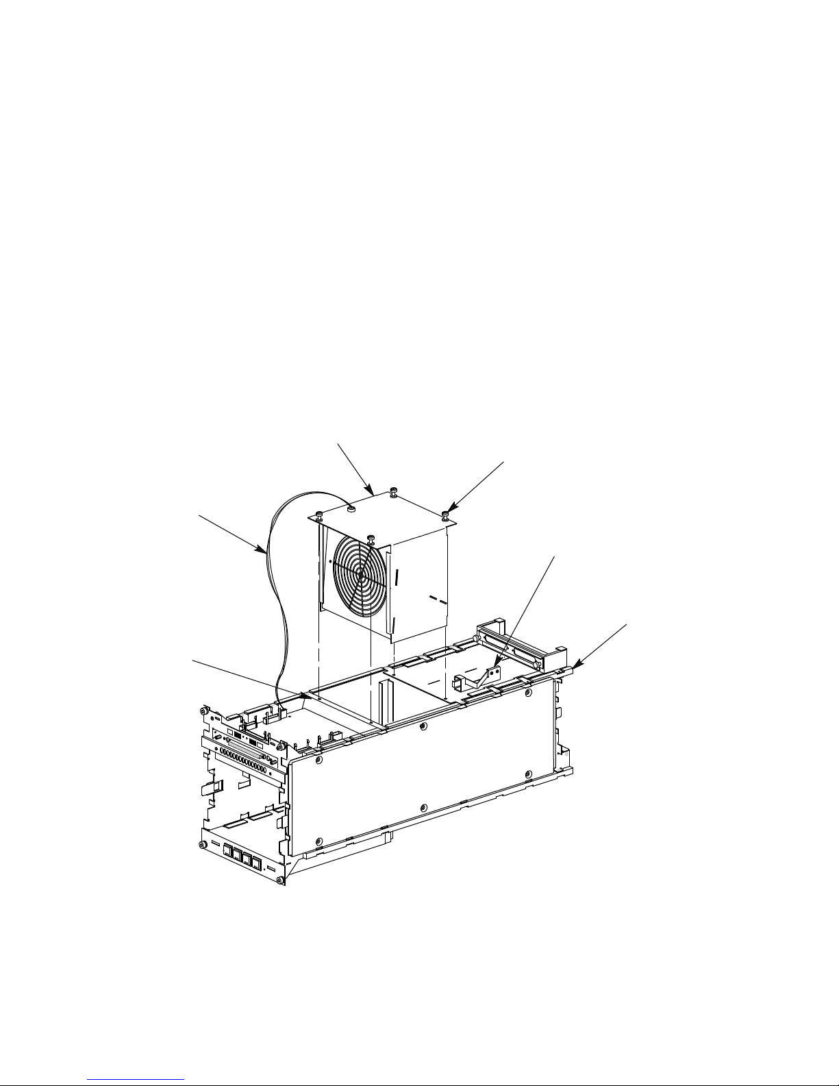
2.3 SA7x Fan Assembly
The SA7x fan assembly consists of an axial fan mounted in a case. The fan
assembly slides into a recess in the center portion of the frame and is secured
with four mounting screws, as shown in Figure 2–3.
Connector J1 on TB2 supplies +12.6 Vdc to the fan. Other fan-related signals
in this connector include the fan control signal to the fan and the fan rotation
sensor signal from the fan. The fan rotation signal is processed on TB2 for fan
speed control. A fan failure signal, derived from fan rotation, is sent to the power
supply.
Figure 2–3 SA7x Fan Assembly
SA7x Technical Description
2.3 SA7x Fan Assembly
FAN
CABLE
FRAME
SHEET
METAL
FAN
MOUNTING
SCREWS
(4 PLACES)
LATCH
FRAME
CXO-2613B
SA7x Technical Description 2–5

SA7x Technical Description
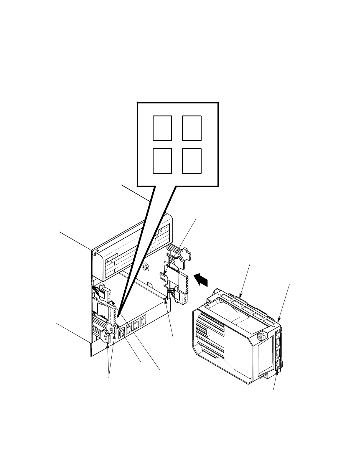
2.4 SA7x OCP and Transition Board Assembly
2.4 SA7x OCP and Transition Board Assembly
The OCP consists of a plastic bezel, an electronic emissions (EMI) shield, a
plastic retainer, and a three-module circuit board set. The OCP assembly is
designed to be a one-piece field replaceable unit (FRU). An associated transition
board assembly is fastened to the SA7x frame. The OCP connects to TB1 with a
96-pin male connector and two clip/bullet fasteners (located on either side of the
connector). TB2 interfaces to TB1 through two ribbon cables.
The OCP communicates through the transition board assembly with up to four
RA7x disk drives. Each OCP control set contains the following, as shown in
Figure 2–4:
• Run switch
• Fault/Set No. switch
• Write Protect switch
• Port A switch
• Port B switch
• Unit No. display
Note
The OCP Unit Selector switch puts the OCP into the unit select mode.
This unit select function allows you to change any drive unit number
without interrupting the operation of the remaining disk drives. The unit
numbers may be either from 000 to 255 or from 000 to 999, depending on
the revision level of TB2.
The OCP can be installed in either the right or left side of the enclosure frame,
depending upon the enclosure’s position in the cabinet. A block diagram of the
OCP and transition board assembly is shown in Figure 2–5.
The transition board assembly consists of two individual boards: TB1 and TB2.
TB2 transfers signals from each of the four disk drives through two 40-pin cables
to TB1. TB1 transfers the drive signals through the single OCP connector to the
OCP.
Circuits on TB2 determine the power up/down protocol for the disk drives. The
protocol is derived through comparator circuits that monitor the ACOK line and
individual drive power switch status on one input, and a reference voltage on the
other input. The comparator outputs provide individual ACOK signals for each
drive and provide dc control from the power supply to the disk drives through the
drive power switches. In the power supply, these control signals are the on/off
controls for the individual regulators that provide the power for each disk drive.
Each of the drive power switches is a grounded circuit when the switch is off;
turning the power switch on removes the ground and signals status back to TB2.
TB1 monitors the incoming ambient air temperature and sends a control signal to
a driver circuit in the fan assembly to operate in low-speed mode if the air inside
the enclosure is within operating limits. If the air temperature rises above preset
limits, the control signal is removed by TB1 and the fan changes to high-speed
operation.
2–6 SA7x Technical Description

SA7x Technical Description
2.4 SA7x OCP and Transition Board Assembly
Note
The supply voltage to the fan does not change when the fan speed is
changed. Rather, the presence or absence of a control signal to the fan
produces the two-speed operation.
A fan rotation signal from the fan assembly is processed on TB2 and sent to the
power supply as ‘‘fan OK.’’ When the fan OK signal is lost, or when abnormal
ambient air temperature in the enclosure is detected, logic in the power supply
shuts down the enclosure.
Power and ground signals for each set of switches and indicators on the OCP
come from the associated disk drive through TB2. When a drive is not installed
in a disk drive position, the associated OCP is inactive and the corresponding
display is blank.
Asserting an OCP switch places an active low on its line to the disk drive; status
signals from the disk drive are active low to identify it as a state on a logic line.
SA7x Technical Description 2–7

SA7x Technical Description
2.4 SA7x OCP and Transition Board Assembly
Figure 2–4 SA7x Enclosure Front Panel and OCP
LEFT
REAR
LEFT
FRONT
Run
PORT SWITCHES
Fault/
Ready Ready
Set No. Set No.
Unit No.
A A
Write Write
Protect Protect
B
Run
Fault/
PORT SWITCHES
Unit No.
Unit Select
B
RIGHT
REAR
RIGHT
FRONT
LEFT
FRONT
LEFT
REAR
FRONT
COVER
DRIVE
POWER SWITCHES
RIGHT
REAR
RIGHT
FRONT
CXO-1867D_S
2–8 SA7x Technical Description
 Loading...