

Digital Equipment RW504-ZA, RW524-ZA Service Manual

SmallOpticalDiskLibrary
ServiceManual
Part Number: EK–SOL10–SV.B01
Revision/Update Information: This manual supersedes Part Number
EK–SOL10–SV.A01.
Digital Equipment Corporation
Maynard, Massachusetts

First printing, May 1993
Revision, October 1993
The information in this document is subject to change without notice and should not be
construed as a commitment by Digital Equipment Corporation. Digital Equipment Corporation
assumes no responsibility for any errors that may appear in this document.
The software described in this document is furnished under a license and may be used or copied
only in accordance with the terms of such license.
Digital Equipment Corporation assumes no responsibility for the use or reliability of its software
on equipment that is not supplied by Digital or its affiliated companies.
© Digital Equipment Corporation 1993.
Reproduced with Permission of the Hewlett-Packard Company
The following are trademarks of Digital Equipment Corporation: DEC, Digital, VAX,
VAX DOCUMENT, VMS, and the DIGITAL logo.
Torx is a registered trademark of the Camcar Division of Textron.
All other trademarks and registered trademarks are the property of their respective owners.
U.S.A.
This equipment generates, uses, and may emit radio frequency energy. The equipment has
been type tested and found to comply with the limits for a Class A computing device pursuant
to Subpart J of Part 15 of FCC Rules, which are designed to provide reasonable protection
against such radio frequency interference. Operation of this equipment in a residential area may
cause interference in which case the user at his own expense will be required to take whatever
measures may be required to correct the interference.
This document was prepared using VAX DOCUMENT, Version 2.1.

Contents
Preface ................................................ xi
1 Introduction
1.1 Optical Disk Libraries Overview .................... 1–1
1.2 Product Features . ............................... 1–1
1.3 Optical Library Components ....................... 1–2
1.3.1 The Optical Drive Mechanism ................... 1–4
1.3.2 Magneto-Optical Disks . . ....................... 1–5
1.4 SCSI Interface Options ........................... 1–5
1.4.1 Single-ended SCSI Interface .................... 1–5
1.4.2 Differential SCSI Interface ..................... 1–6
1.5 Product Matrix . . . ............................... 1–6
1.6 Specifications ................................... 1–7
1.7 Optical Disk Specifications . . ....................... 1–12
1.8 Related Documents .............................. 1–14
2 Environmental/Installation/PM
2.1 Environmental Requirements ...................... 2–1
2.2 Operating Temperature/Clearance Requirements. . ...... 2–1
2.3 Location Requirements ........................... 2–1
2.4 Primary Power/External Ground .................... 2–2
2.5 Unpacking Procedure ............................. 2–2
2.6 Installation Procedures ........................... 2–3
2.6.1 Contents of Shipment . . ....................... 2–3
2.6.2 Uncrating the RW504/RW524 Optical Library . ...... 2–4
2.6.3 Installing the RW504/RW524 Optical Library . ...... 2–4
2.6.4 Checking the Fuse and Voltage Setting ............ 2–9
2.6.4.1 Changing the Voltage Configuration ........... 2–10
2.6.5 Connecting an Uninterruptible Power Supply
(UPS) ...................................... 2–10
2.7 Hardware Verification ............................ 2–11
iii

2.8 Moving the RW504/RW524 Optical Disk Library . . ...... 2–12
2.8.1 Moving a Short Distance ....................... 2–12
2.8.2 Shipping the RW504/RW524 Optical Disk Library .... 2–13
2.9 Preventative Maintenance . . ....................... 2–15
3 Product Operation and Configuration
3.1 Front Panel/Control Panel Operations . ............... 3–1
3.2 Rear Panel Features and Controls ................... 3–3
3.3 Setting and Displaying Configurations . ............... 3–5
3.3.1 Setting a Configuration (CONF) . . . ............... 3–5
3.3.2 Displaying Information Logs (INFO) .............. 3–5
3.3.3 Choosing Tests and Displaying Results (TEST) ...... 3–6
3.3.4 Setting the SCSI Address....................... 3–7
3.3.5 Securing the Optical Disk Library . ............... 3–8
3.3.6 Setting a New Security Code .................... 3–8
3.3.7 Restricting Disk Insertion and Removal ........... 3–10
3.3.7.1 Setting CONF 15 or CONF 20 . ............... 3–10
3.3.8 Controlling Mailslot Rotation .................... 3–11
3.3.9 Host Configuration ............................ 3–11
3.4 Autochanger Configuration Choices . . . ............... 3–12
4 Troubleshooting and Diagnostics
4.1 Operation/Installation Error Information.............. 4–2
4.2 Power-on Self-tests............................... 4–6
4.3 Optical Disk Cleaning ............................ 4–7
4.3.1 Cleaning Tools Available ....................... 4–8
4.4 Using the Eject Tool to Remove a Disk from the Drive . . . 4–9
4.5 Troubleshooting Using the Control Panel and
Observation .................................... 4–10
4.5.1 The Autochanger Lists the First ‘‘Possibles’’ . . ...... 4–11
4.5.2 How to Use the Results of the Internal Tests. . ...... 4–12
4.5.3 The FRU Isolation Test Sequence . ............... 4–14
4.6 Information Logs . ............................... 4–15
4.7 Recovery from Hardware Errors .................... 4–20
4.7.1 Hardware Error Codes and Recovery Procedures ..... 4–20
4.8 Error Information Through SCSI Commands .......... 4–30
4.9 Diagnostics..................................... 4–31
4.9.1 Offline Diagnostics ............................ 4–32
4.9.2 Internal Diagnostic Tests ....................... 4–32
4.10 Diagnostic Test Command Descriptions ............... 4–33
4.10.1 Sequence Tests ............................... 4–34
iv

4.10.2 Electronic Core Tests . . ....................... 4–38
4.11 The FIND HOME Sequence and Information Logs ...... 4–41
4.11.1 Specific Steps of the FIND HOME Sequence . . ...... 4–41
4.12 Micro-Move Reference Table for Viewing FIND HOME
Sequence ...................................... 4–44
5 Removal and Replacement
5.1 Field-Replaceable Assemblies ....................... 5–1
5.2 ESD Precautions . ............................... 5–1
5.3 Tools Required . . . ............................... 5–2
5.4 Assembly/Disassembly Procedures ................... 5–2
5.4.1 Service Access ............................... 5–2
5.4.2 Replacing the Autochanger Controller PCA . . . ...... 5–4
5.4.3 Replacing the Front Bezel Assembly .............. 5–8
5.4.4 Replacing the Front Operation Switch/Cable
Assembly ................................... 5–10
5.4.5 Replacing the Fan/Display/Operation Button
Assemblies . . . ............................... 5–12
5.4.6 Replacing the Mailslot Assembly . . ............... 5–14
5.4.7 Replacing the Optical Drive Mechanism ........... 5–16
5.4.8 Replacing the Interconnect PCA . . ............... 5–22
5.4.9 Replacing the Picker/Carriage Assembly ........... 5–23
5.4.10 Replacing the Leadscrew Assembly ............... 5–26
5.4.11 Replacing the Power Supply .................... 5–29
5.4.12 Replacing the Magazine Guides . . . ............... 5–31
5.4.13 Replacing the Internal UPS Cable . ............... 5–33
5.4.14 Replacing the SCSI Cable ...................... 5–33
5.5 Reinitializing the Autochanger Controller PCA RAM after
Service . ....................................... 5–34
5.5.1 Variables Set by Configuration 16 . ............... 5–34
5.5.2 Variables Set by Configuration 18 . ............... 5–35
5.6 Replaceable Parts. ............................... 5–36
5.6.1 Recommended Service Kit ...................... 5–36
6 Theory of Operation
6.1 The Autochanger . ............................... 6–1
6.1.1 Movements . . . ............................... 6–1
6.1.2 Mechanics . . . ............................... 6–4
6.2 The Autochanger Controller PCA .................... 6–4
6.3 The Power Supply ............................... 6–7
6.4 The Multifunction Optical Drive and Drive Controller.... 6–8
v

6.4.1 Controller PCA............................... 6–8
6.4.1.1 SCSI Controller ........................... 6–9
6.4.1.2 Data Buffer .............................. 6–9
6.4.1.3 Formatter/Sequencer ....................... 6–9
6.4.2 Servo PCA . . . ............................... 6–9
6.4.2.1 DSP Microprocessor and Support/Servo Control
Loops ................................... 6–9
6.4.2.2 Read and Write Channel Electronics ........... 6–10
6.4.3 Mechanism Assembly . . . ....................... 6–10
6.4.3.1 Loader Mechanism . . ....................... 6–10
6.4.3.2 Optical Head ............................. 6–10
6.5 Optical Disk Layout and Error Correction ............. 6–10
6.5.1 Optical Disk Layout—650-Mbyte Capacity.......... 6–11
6.5.2 User Zone Layout—650-Mbyte Capacity ........... 6–11
6.5.3 Optical Disk Layout—1.3-Gbyte Capacity .......... 6–14
6.5.4 User Zone Layout—1.3-Gbyte Capacity ............ 6–14
6.5.5 Drive Defect Management ...................... 6–18
6.5.6 Slip Sparing Algorithm . ....................... 6–20
6.5.7 Replacement Sparing Algorithm . . ............... 6–20
6.5.8 Error Thresholds ............................. 6–21
6.6 Error Detection and Recovery ...................... 6–22
6.6.1 Error Detection .............................. 6–23
6.6.2 Error Recovery Processes ....................... 6–24
6.6.3 SCSI Detected Errors . . . ....................... 6–24
6.6.4 Move Errors . . ............................... 6–25
6.6.5 Hardware Error Codes . . ....................... 6–26
6.6.6 Real Time Event Logging ....................... 6–26
6.7 The SCSI Interface .............................. 6–27
6.7.1 SCSI Command Set ........................... 6–27
A Offline Diagnostic Information
A.1 System Error Report ............................. A–1
A.2 Autochanger Error Codes . . . ....................... A–3
A.3 Drive SCSI-2 Reference ........................... A–13
A.4 Offline Diagnostics ............................... A–27
vi

B Basic Supplies and Reorderable Parts
B.1 Basic Supplies and Reorderable Parts . ............... B–1
C Connecting Multiple Optical Libraries
C.1 Connecting Two Optical Library Units to Two SCSI Ports
.............................................. C–1
C.2 Connecting Two Optical Library Units to One SCSI
Port . . . ....................................... C–2
C.3 Resetting Controller and Drive SCSI Addresses . . ...... C–3
Index
Figures
1–1 Optical Disk Library Components . ............... 1–3
2–1 Removing the Shipping Screw ................... 2–4
2–2 Attaching the SCSI Cable to the RW504/RW524
Optical Disk Library . . . ....................... 2–6
2–3 Rear Panel . . . ............................... 2–8
2–4 Replacing the Shipping Screw ................... 2–14
3–1 Front Panel . . ............................... 3–1
3–2 Rear Panel . . . ............................... 3–3
4–1 Information and Tests Through the Control Panel .... 4–10
4–2 The Autochanger Returns Suspect FRUs ........... 4–11
4–3 How Service Views the Suspect FRUs ............. 4–13
4–4 Information and Tests Through the SCSI Bus . ...... 4–31
5–1 Controller PCA Cable Connections . ............... 5–5
5–2 Removing the Autochanger Controller PCA . . . ...... 5–6
5–3 Dip Switch Location on the Controller PCA . . . ...... 5–7
5–4 Front Bezel Mounting Screws ................... 5–9
5–5 Disconnecting the Mailslot Sensor Cable and Front
Panel Cable . . ............................... 5–10
5–6 Removing the Display Assembly . . ............... 5–13
5–7 Mailslot Mounting Screws ...................... 5–15
5–8 Picker Service Position . . ....................... 5–17
5–9 Optical Drive Mechanism Cable Connections . . ...... 5–18
vii

5–10 Drive Mounting Screws and Optical Sensor Cable
Locations ................................... 5–19
5–11 Sliding the Drive Mechanism Out of the Library ..... 5–20
5–12 Removing the Drive Plate and Optical Sensor . ...... 5–21
5–13 Removing the Interconnect PCA . . ............... 5–23
5–14 Removing the Carriage/Picker Assembly ........... 5–24
5–15 Removing the Carriage Shaft .................... 5–25
5–16 Removing the Leadscrew Mounting Screw .......... 5–26
5–17 Securing the Picker to the Top of the Autochanger . . . 5–27
5–18 Removing the Leadscrew Assembly ............... 5–28
5–19 Preparing the Leadscrew Assembly for
Replacement. . ............................... 5–29
5–20 Removing the Power Supply Assembly ............ 5–30
5–21 Removing the Magazine Guides . . . ............... 5–32
5–22 Optical Disk Library Exploded View (Sheet 1 of 3) . . . 5–39
5–23 Optical Disk Library Exploded View (Sheet 2 of 3) . . . 5–40
5–24 Optical Disk Library Exploded View (Sheet 3 of 3) . . . 5–41
6–1 SCSI Command Translation for Autochanger
Operation ................................... 6–2
6–2 Autochanger Controller PCA Block Diagram . . ...... 6–5
6–3 Functional Diagram ........................... 6–8
6–4 Optical Disk Layout ........................... 6–12
6–5 User Zone Layout for 650-Mbyte Media ............ 6–13
6–6 User Zone Layout for 1.3-Gbyte Media, g=1 . . . ...... 6–15
6–7 User Zone Layout for 1.3-Gbyte,g=16 .............. 6–16
6–8 Error Detection and Recovery ................... 6–22
A–1 System Error Report . . . ....................... A–2
A–2 Jukebox Request Sense Data Parameter Block
Format ..................................... A–3
A–3 Jukebox Request Sense—Additional Sense Data ..... A–5
A–4 Drive Request Sense Data Parameter Format . ...... A–14
C–1 Connecting Two Optical Library Units (RW504/RW524)
to One SCSI Port ............................ C–2
viii

Tables
1 Conventions Used in This Guide . . ............... xii
1–1 RW504/RW524 Components ..................... 1–4
1–2 Optical Disk Library Products Matrix ............. 1–6
1–3 Specifications and Characteristics of Optical Disks . . . 1–12
1–4 Related Documentation . ....................... 1–14
1–5 Pass Documents .............................. 1–14
2–1 Fuse Specifications and Part Numbers ............ 2–9
2–2 UPS Power Requirements ...................... 2–11
3–1 Front Panel Controls . . . ....................... 3–2
3–2 Rear Panel Features and Controls . ............... 3–3
3–3 Autochanger Configuration Choices ............... 3–12
4–1 Operation/Installation Troubleshooting ............ 4–2
4–2 Information Logs (INFO Logs) ................... 4–16
4–3 Recovery Procedures for Specific Hardware Errors . . . 4–21
4–4 Sequence Tests ............................... 4–34
4–5 Exerciser Tests ............................... 4–36
4–6 Electronic Core Tests . . . ....................... 4–38
4–7 RW504/RW524 Micro-Move ID Table .............. 4–44
5–1 SW2 Default Settings . . . ....................... 5–8
5–2 Exchange Assemblies . . . ....................... 5–36
5–3 Non-exchange Assemblies ...................... 5–37
6–1 Values for n and m for 1.3-Gbyte with g=16 (1024
media) ..................................... 6–17
6–2 Physical Revolution to Logical Track Layout . . ...... 6–17
6–3 Error Thresholds ............................. 6–22
6–4 Group 0 Commands (6-byte command) ............ 6–28
6–5 Group 1 and 2 Commands (10-byte command) . ...... 6–29
6–6 Group 5 Commands (12-byte command) ............ 6–30
A–1 Sense Key and Additional Sense Length Values ..... A–4
A–2 Autochanger Move Errors ...................... A–9
A–3 Autochanger Micro-Move Error Codes ............. A–11
A–4 Drive Request Sense - Additional Sense Code
Values ..................................... A–16
A–5 HP-Specific Drive Error Codes ................... A–19
ix


Preface
This manual assumes you are familiar with computer terms. It is divided into
seven chapters and three appendixes and is organized to allow you to quickly
find the information that you need.
This manual contains the following information:
• Chapter 1 provides an introduction that lists the features and components,
product configurations, and the characteristics of the drive mechanism and
the disks for the RW504-ZA and the RW524-ZA optical disk libraries. This
manual refers to these optical disk libraries as RW504 and RW524.
• Chapter 2 provides environmental, installation and preventive maintenance information on the RW504 and RW524 optical disk libraries.
• Chapter 3 provides configuration and operating information on the RW504
and RW524 optical disk libraries.
• Chapter 4 provides troubleshooting and diagnostics information on the
RW504 and RW524 optical disk libraries.
• Chapter 5 provides removal and replacement procedures for the fieldreplaceable assemblies in the RW504 and RW524 optical disk libraries.
• Chapter 6 provides theory of operation information on the RW504 and
RW524 optical disk libraries.
• Appendix A provides offline diagnostic information, a VAX system error
report sample and SCSI-2 reference.
• Appendix B provides a list of basic supplies and reorderable parts.
• Appendix C lists information about, and procedures for, connecting multiple
optical libraries.
xi

Conventions Used in This Guide
Table 1 Conventions Used in This Guide
Convention Use
Italics Italic text is used for titles of manuals and other publications.
Monospace type Anything that is displayed on the control panel of the
optical disk library is set in this monospace type.
Boldface type Anything that you are asked to type is set in this
Keys Keys
Note A note calls attention to information which is helpful in
CAUTION Caution notes provide information that protects your optical
WARNING Warning notes provide information that protects you from being
boldface type.
indicate the key to press on the control panel of the
optical disk library.
understanding the operation of the product.
disk library from being damaged.
harmed.
xii

1
Introduction
1.1 Optical Disk Libraries Overview
The RW504-ZA and RW524-ZA are optical disk libraries that contain a
multifunction optical drive. They have storage slots for sixteen 5.25-inch
optical disks for a total storage capacity of 10 Gbytes or 20 Gbytes, respectively.
Both rewritable and write-once optical disks can be used; they must be 512 bytes
per sector format.
There are two basic optical disk libraries:
• RW504-ZA (known as the RW504)
• RW524-ZA (known as the RW524)
The main difference between these two library versions is storage capacity. The
RW524 has approximately twice the storage capacity of the RW504. This added
capacity is due to a difference in the optical drives contained in the libraries. The
RW524 contains a 1.3-Gbyte drive, an enhanced version of the 650-Mbyte drive
that is used in the RW504 version libraries. The 1.3-Gbyte drive supports the use
of 1.2-Gbyte disks as well as the 594-Mbyte disks that are supported for use with
650-Mbyte drives. Other than the added support of 1.2-Gbyte disks, the RW524
libraries are mechanically, electrically, and operationally the same as the RW504
libraries, and both versions support the SCSI-2 command set.
1.2 Product Features
The optical disk library has the following features and meets the following
specifications:
• Direct online access to data
• High reliability and data security when using rewritable and write-once
5.25-inch optical disks
Introduction 1–1

DEC magneto optical disks meet the following standards:
594 Mbyte rewritable optical disks are Continuous Composite (CC)
format, conform to ISO/IEC 10089A; ANSI X3.212-199x and 1.2 Gbyte
optical disks meet ECMA 184 standard for CC format.
594 Mbyte write-once disks are Continuous Composite Write-Once (CCW)
format, conform to ISO/IEC DIS 11560; ANSI X3.220-199x and 1.2 Gbyte
optical disks meet ECMA 184 standard for CCW format.
• Data security through the ability to ‘‘lock’’ the library, preventing disk
removal.
• SCSI Interface
Single-ended
SCSI-2 command set
• Autochanger reliability of:
40,000 hours MTBF (Mean Time Between Failure)
300,000 MSBF (Mean Swaps Between Failure)
• Modular replacement of all major assemblies
• Digital signal processor (DSP) based servo built into the drive mechanism for
faster seek times and lower error rates
• Split optics resulting in the use of a lighter optical head for faster and more
accurate data access
• Full read and write data caching to optimize system performance
1.3 Optical Library Components
Usually each SCSI-connect peripheral requires one SCSI address. With the disk
library, however, there are two unique SCSI interface addresses— one SCSI
address for the autochanger controller and one for the drive contained in the disk
library.
The autochanger controller and the host operating system manage communication
through the SCSI bus to each drive’s unique SCSI address.
Table 1–1 is a discussion of the optical library components. Refer to Figure 1–1
for component locations.
1–2 Introduction
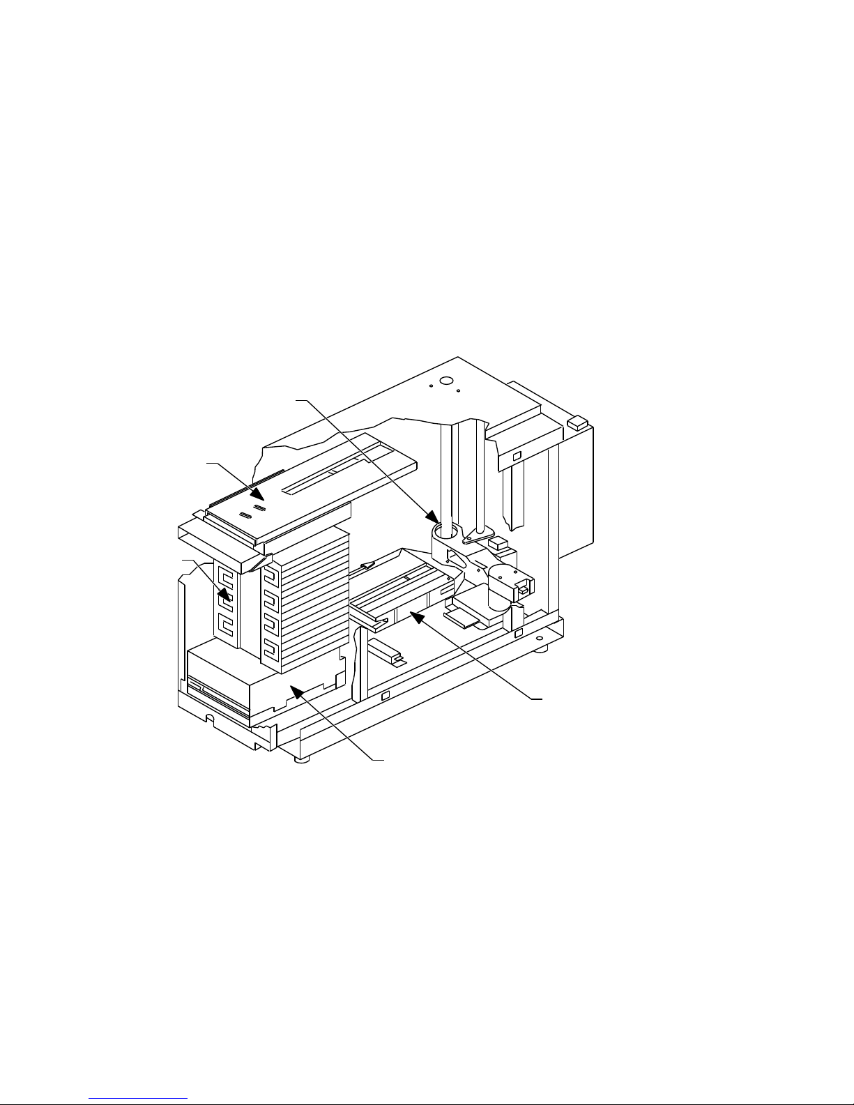
Figure 1–1 Optical Disk Library Components
Carriage & Rails
6
Mailslot
3
Storage Slots
2
7
Picker
1
Disk Drive
MK445−01
Introduction 1–3

Table 1–1 RW504/RW524 Components
Component Description
Disk Drive The optical disk library contains one multifunction optical
Storage Slots The optical disk library contains 16 storage slots for holding
Mailslot The mailslot is used to insert or remove optical disks from the
Front Panel The front panel includes a control panel used to manage and
Rear Panel The rear panel includes SCSI and power cord connections,
Rail and Carriage The rail and carriage support the picker for its movement
Picker The picker rotates, flips, and transports optical disks to and
disk drive for read/write data transfer. The drive requires
its own unique SCSI address and is located next to the front
panel at the bottom of the optical library. See Section 1.3.1 for
additional drive information.
optical disks.
disk library.
display library functions and a mailslot for inserting and
removing disks. Control panel functions are described in
Section 3.1.
a fuse receptacle, a 9-pin serial connector for attaching an
uninterruptable power supply (UPS), and a voltage select
switch.
within the disk library.
from the storage slots, mailslot, and optical drive.
The RW504/RW524 is available as a single-ended SCSI interface.
1.3.1 The Optical Drive Mechanism
The optical drive mechanism is a multifunction drive and, therefore, operates
in both rewritable and write-once modes. The drive uses both rewritable and
write-once 5.25-inch magneto-optical disks that comply with ANSI and ISO
standards for Continuous Composite format. The drive senses the disk type and
automatically operates in either rewritable or write-once mode.
The drive has a 3600 rpm rotational speed and can achieve a maximum sustained
write transfer rate of 0.5 to 0.8 Mbytes per second and a maximum sustained
read transfer rate of 1- to 1.6-Mbyte per second, depending on the media and
drive capacity. The error rate is less than one block in error per
Immediate response mode and write caching are used by the drive mechanism
to achieve its high write performance. However, if a power failure occurs while
write data is in the buffer, the drive may not have enough power to complete
the write operation and empty the buffer. Therefore we recommend that an
1–4 Introduction
10
14
bytes.

uninterruptable power supply (UPS) be used with battery backup to ensure that
no data is lost if a power failure occurs.
1.3.2 Magneto-Optical Disks
Magneto-Optical (MO) disks are more durable, more reliable, removable, and cost
far less per megabyte than magnetic disks. MO disks are made of the same kind
of plastic used in bullet-proof windows. Data can be read through fingerprints
and minor scratches. MO disks can withstand x-rays, magnetic interference, and
can be dropped from desk height without damage.
Magneto-Optical disks store data on a magnetic layer in the form of magnetic
flux reversals rather than on a pitted surface used in other optical technologies.
Because surfaces of the MO disk are not physically changed, they can be written
to and erased repeatedly with no measurable data degradation. Optical disks
have an archival life of thirty years based on accelerated life tests for data
retention.
The disk is mounted in a rigid plastic case with a metal shutter, similar to a
3.5-inch magnetic flexible disk. Optical disk storage capacity varies depending
on the disk type. (Check the host system documentation to determine which disk
format is supported.) The MO disk has two recording sides. To access the second
side, the cartridge must be ejected, turned over, and reinserted into the drive.
There are two types of magneto-optical disks: rewritable optical disks and writeonce optical disks. (Check the host system documentation to determine which
disk type(s) are supported.) The two disk types can be differentiated by the words
‘‘rewritable’’ or ‘‘write-once’’ printed on the disk’s metal shutter.
For data safety, you can independently write-protect each side of the disk by
setting the write-protect tab on the corner of the cartridge.
1.4 SCSI Interface Options
The optical disk library connects to the host system with a single-ended SCSI
interface This interface conforms to SCSI standards ANSI X3.131-SCSI-2.
1.4.1 Single-ended SCSI Interface
The single-ended interface specifies the use of a single-ended SCSI repeater PCA.
This PCA enables the library to be connected to an external single-ended SCSI
bus. The total SCSI cable length between peripherals and the host is 6 meters.
In addition, an internal SCSI cable length of 2.1 meters must be included in this
calculation.
Introduction 1–5

1.4.2 Differential SCSI Interface
The differential SCSI interface specifies the use of a differential SCSI repeater
PCA. This PCA enables the library to be connected to an external differential
SCSI bus. The differential SCSI repeater PCA uses the equivalent of 10 meters
of SCSI cable internally, so the allowable external cable length is limited to 15
meters instead of the 25 meters usually allowed on a differential SCSI bus.
1.5 Product Matrix
The following products are discussed in this manual. To determine the product
and option numbers, find the product information labels located on the library’s
rear panel and check the corresponding information in Table 1–2.
Table 1–2 Optical Disk Library Products Matrix
Product No.
/Options Description HP Designation
RW504-ZA 10.4-Gbyte multifunction optical disk library—
includes one 650-Mbyte 5.25-inch multifunction
optical drive mechanism and a single-ended SCSI
interface.
RW524-ZA 20.8-Gbyte multifunction optical disk library—
includes one 1.3-Gbyte 5.25-inch multifunction
optical drive mechanism and a single-ended SCSI
interface.
RW524-UB Converts 650-Mbyte multifunction drives to 1.3
Gbyte multifunction drives to be used with a
RW504 jukebox. Consists of one 1.3-Gbyte drive,
RFI shield, and installation guide.
Model 10LC
(C1718C)
Model 20LT
(C1718T)
1–6 Introduction

1.6 Specifications
This section provides:
• Performance Specifications
• Physical Characteristics
• Environmental Specifications
• Power Requirements
• Service Characteristics
• Product Certification
Introduction 1–7

Performance Specifications
Optical Disk Library System
Capacity 16 disks
10.4 Gbytes (RW504) or
20.8 Gbytes (RW524)
Drives 1, 5.25-inch multifunc-
Average disk exchange time (excluding
drive load/unload sequences)
Interface Single-ended asyn-
Multifunction Optical Drives
Rotational speed 3600 rpm 2400 rpm
Average seek 25 ms 23.5
Short stroke seek (across 2.2 Mbytes) 8 ms 4 ms
Full stroke seek 50 ms 45 ms
Single track seek (track-to-track) 2 ms 2 ms
Average rotational delay 8.33 ms 12.5 ms
Bias magnet rotation time 8 ms (maximum) 8 ms (maximum)
Average access time 35 ms
Burst transfer rate 3 Mbytes/s (asyn-
Data transfer rate (host dependent) 1 Mbyte/s (read) .8-1.6 Mbyte/s
Load time (including spin-up) 2.5 seconds (average) 2.3 seconds
Unload time (including spin-down) 2.0 seconds (average) 1.4 seconds
tion 650-Mbyte (RW504)
or 1.3-Gbyte (RW524)
optical disk drive
7 seconds
chronous SCSI
650 Mbytes 1.3 Gbytes
chronous)
5 Mbytes/s (syn-
chronous)
.5 Mbytes/s (write) .4-.8 Mbytes/s
3 Mbytes/s
(asynchronous)
5 Mbytes/s
(synchronous)
(read)
(write)
(average)
(average)
1–8 Introduction

Multifunction Optical Drives
650 Mbytes 1.3 Gbytes
Read/Write error rate Less than 1 block in
error per
Seek error rate Less than 1 per
10
14
bytes
10
5
seeks
Interface SCSI-2
single-ended
RW504/RW524 Physical Characteristics
Height 493.8 mm (19.4 in)
Width 220.0 mm (8.7 in)
Depth 693.4 mm (27.3 in)
Weight (net) 34.9 kg (77.5 pounds)
Weight (packaged) 40.8 kg (90.0 lbs)
RW504/RW524 Environmental Specifications
Temperature gradient 10° C per hour
Temperature (operating) 10° to 40° C
Temperature (nonoperating) -40° to 70° C
Relative humidity (noncondensing)
operating 10 to 90%
nonoperating 5 to 95%
Max. wet bulb temperature 29° C
Shock (nonoperating) 292 ips (30 g trape-
zoidal)
Vibration (5-500 Hz)
operating ~0.21 g rms
nonoperating, random ~2.09 g rms
nonoperating swept-sine 0.5 g peak
Altitude (operating) 15,000 ft (4,572 m)
Altitude (nonoperating) 50,000 ft (15,240 m)
Acoustic emissions
Less than 1 block
in error per
10
14
bytes
SCSI-2
single-ended
Introduction 1–9

RW504/RW524 Environmental Specifications
operating 61.5 dB (L noise power
emission level)
idle 47 dB (L noise power
emission level)
Particulates Less than 200
micrograms/cubic meter
particles suspended
Electrostatic discharge
Airgap (operating) 0 to 10 kV
Airgap (nonoperating survival) 0 to 25 kV
Direct contact (operating) 0 to 5 kV
Direct contact (nonoperating survival) 0 to 8 kV
Cooling requirements 15 CFM bidirectional
through drive
RW504/RW524 Power Requirements
Line voltage (115V setting) 100-127V
Line voltage (230V setting) 200-240V
Line frequency 50-60Hz
Power consumption (typical) Less than 70 W
Power consumption (maximum) 100 W
RW504/RW524 Service Characteristics
Mean time between failure 40,000 power-on hours
Mean swaps between failure 300,000
Mean time to repair 1 hour
Preventive maintenance none required
RW504/RW524 Product Certifications
Safety EN 60950/IEC 950
1–10 Introduction
UL 1950 listed or
recognized
CSA 950-M89
TUV approved to VDE
0805 05.90

RW504/RW524 Product Certifications
Electromagnetic emissions FCC 47 CFR Part 15
Subpart J - Class ‘‘B’’
EN 55022/CISPR 22,
Level ‘‘B’’; SABS
VCCI Level 2
Laser CDRH 21 CFR Chapter
1, Subpart J Registered
IEC 825
TUV approved to
VBG93, VDE 0837
TTL to Decision 472
BS 4803 part 2
Approved
Introduction 1–11

1.7 Optical Disk Specifications
Table 1–3 Specifications and Characteristics of Optical Disks
Physical Characteristics Rewritable Write-once
Disk 5.25 in. diameter (130 mm) 5.25 in. diameter (130
mm)
Capacity (512-byte
sectors) (1x)
Capacity (512-byte
sectors) (2x)
1
2
594 Mbytes (297 Mbytes/side)
(formatted)
1.2 Gbytes (594 Mbytes/side)
(formatted)
Format (1x) Continuous Composite (CC)
594 Mbytes (297 Mbytes
/side) (formatted)
1.2 Gbytes (594 Mbytes
/side) (formatted)
CCW (ISO 11560)
(ISO 10089)
Format (2x) Continuous Composite (CC)
(ISO 10089),ECMA 184 for CC
format
CCW (ISO 11560), ECMA
184 standard for CCW
format
Bytes per sector 512 (medium dependent) 512 (medium dependent)
Sectors per track 31 (medium dependent) 31 (medium dependent)
Physical tracks per side
18751 18751
(1x)
Physical tracks per side
21600 21600
(2x)
Physical tracks per inch
15875 15875
(1x)
Physical tracks per inch
18273 18273
(2x)
Error Rate Less than 1 block in error per
10
14
bytes
Less than 1 block in error
14
per
10
bytes
Security Write protect tab (1 per side) Write protect tab (1 per
side)
Medium archival life 30 years 30 years
1
In this table, 1x refers to 594-Mbyte.
2
In this table, 2x refers to 1.2-Gbyte.
1–12 Introduction
(continued on next page)

Table 1–3 (Cont.) Specifications and Characteristics of Optical Disks
Environmental
Specifications Rewritable Write-once
Temperature (operating) 10° to 50° C 10° to 50° C
Temperature (nonoperat-
ing)
Temperature gradient 10° C per hour 10° C per hour
Maximum wet bulb
temperature
Humidity (operating) 10 to 80 percent (noncondensing) 10 to 80 percent
Humidity (nonoperating) 10 to 90 percent (noncondensing) 10 to 90 percent
-10° to 50° C long term
(> 14 days)
-10° to 55° C short-term (
days)
14
-10° to 50° C long term
(> 14 days)
-10° to 55° C short-term (
14 days)
29° C 29° C
(noncondensing)
(noncondensing)
Introduction 1–13

1.8 Related Documents
Table 1–4 Related Documentation
Item Part Number
Optical Disk Library Conversion Kit Installation Guide EK–OLCON–IG
Optical Library User’s Guide (Shipped with each unit) EK–STSOP–UG
Optical Storage Desktop Software Installation Guide AA–PXYKA–TE
Optical Storage Desktop Software User’s Guide AA–PXYLA–TE
Optical Storage Management Software Installation Guide AA–PXYPA–TE
Optical Storage Management Software Installation Guide AA–PXYQA–TE
Storage Server 100 Installation Guide EK–D59SS–IN
Small Optical Disk Library Service Manual EK–SOL10–SV
Medium Optical Disk Library Service Manual EK–MOL20–SV
Large Optical Disk Library Service Manual EK–SS100–SV
Storage Server 100 Optical Disk Service Manual EK–STSOP–SV‡
Optical Disk Library System Technical Reference Manual 5959-3559 (GSD)†
Technical Guide Optical Drives and Libraries 5960-7605†
Optical Drive and Library SCSI-2 Command Reference 5960-7606†
Offline Diagnostics for HP Optical Products 5960-7626†
†These documents can be ordered directly from Hewlett-Packard
‡Only for older model 10/20 Jukebox shipped with (Ninja) storage server systems
Table 1–5 Pass Documents
Pass Entry Number
RW5xx Hardware Pass 7174
Ninja Hardware Pass 6060
Optical Storage Management Software Pass 3731
Optical Storage Desktop Software Pass 3750
1–14 Introduction

2
Environmental/Installation/PM
2.1 Environmental Requirements
Note
The environmental requirements listed here apply when the RW504
/RW524 optical disk library is not connected to a system. When this
device is connected to a system, the more stringent environmental
specifications listed for any single device within the system are applicable
and supersede these specifications.
2.2 Operating Temperature/Clearance Requirements
The RW504/RW524 optical disk library is designed to operate with an ambient
air temperature range of 10° to 40° C (50° to 104° F) with a rate of temperature
change not to exceed 10° C (50° F) per hour.
A minimum 70-80 mm (3 in.) is required behind the RW504/RW524 optical disk
library rear panel to allow air circulation.
2.3 Location Requirements
Position the autochanger away from sources of particulate contamination such
as frequently-used doors and walkways, stacks of supplies that collect dust, and
smoke-filled rooms.
Environmental/Installation/PM 2–1

2.4 Primary Power/External Ground
The power outlet to be used to supply AC power to the RW504/RW524 optical
disk library must be checked to ensure that the proper voltage is available for
the drive. Permitted voltage range(s), depending on configuration and assuming
50-60 Hz, are 100 to 120 Vac and 200 to 240 Vac. Also check the earth (safety)
ground in the power outlet.
2.5 Unpacking Procedure
Check that all materials are included with the disk library (Section 2.6.1). If any
items are missing, please contact the factory Order Processing Center with the
following information:
• Original order number or unit serial number
• Receiving address
If the unit is damaged, it will be repaired or replaced. Billing of the charges
depends on whether the damage was caused by the carrier or the factory
packaging. The cause of damage will be determined by the field service
representative.
Problems determined to be caused by factory packaging should be reported, in
detail, to the factory so a warranty claim can be submitted.
Be sure to include the product number and full serial number in any
correspondence concerning the unit.
2–2 Environmental/Installation/PM

2.6 Installation Procedures
This section provides information on:
• Contents of shipment
• Uncrating and installing an RW504/RW524 optical library
• Connect multiple optical library systems together
Setting up the optical disk library is the customer’s responsibility; however this
service may be contracted for on a time-and-materials basis. Setup instructions
for the disk library are in the Optical Library User’s Guide, part number
EK–STSOP–UG, which is shipped with the product.
The installation and configuration instructions are provided for situations where
the customer has arranged for this service.
Note
Before you connect the optical disk library to the host, verify that the host
supports it. Refer to the Product Support Plan for the most current list of
host systems that support the RW504/RW524 optical disk library.
CAUTION
The shipping screw must be removed from the disk library before
connecting power. Directions for removing the shipping screw are printed
on the carton, or see Figure 2–1 for the location of the shipping screw.
2.6.1 Contents of Shipment
You should receive a crate containing the RW504/RW524 optical library, and
a box, shipped separately, labeled OPEN FIRST. Inside this box are several
additional packages containing the following:
• READ ME FIRST instructions
• Optical Library User’s Guide
• SCSI cable
• SCSI terminator
• Power cord
Environmental/Installation/PM 2–3
In addition to these items, to complete the installation you may need two
wrenches—a 1/2 inch wrench and a 9/16 inch wrench—and a TORX T10, T15,
T20, and T25 screwdriver (the blade is star-shaped) as well as wire cutters or a
knife.
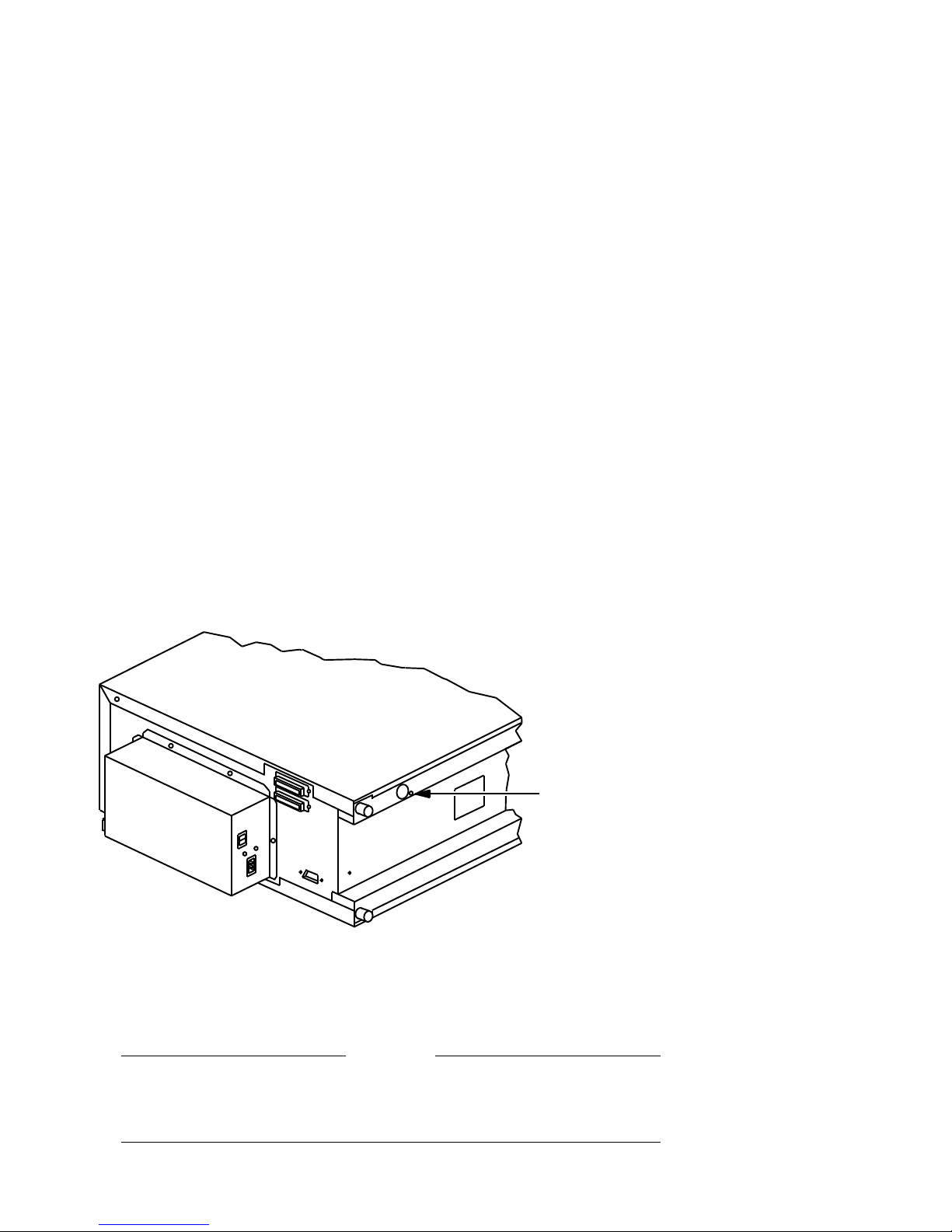
2.6.2 Uncrating the RW504/RW524 Optical Library
1. Uncrate the Optical Library. Remove the packaging material.
2. Lay the unit on its side and remove the shipping screw as shown in
Figure 2–1.
Figure 2–1 Removing the Shipping Screw
Shipping screw
location
2.6.3 Installing the RW504/RW524 Optical Library
The optical disk library has a single-ended SCSI interface. The total allowable
cable lengths for a single-ended SCSI is 3.9 meter.
Do not switch off power to any peripheral on the SCSI bus if the bus is
active. Switching off power to a peripheral on an active bus may cause
data loss, indeterminite bus states, or both.
2–4 Environmental/Installation/PM
MK445−02
CAUTION
 Loading...